18 minute read
DEFECTOSCOPY OF VENEER LAYERED COMPOSITE MATERIALS
ACTA FACULTATIS XYLOLOGIAE ZVOLEN, 62(2): 89−98, 2020 Zvolen, Technická univerzita vo Zvolene DOI: 10.17423/afx.2020.62.2.08
Advertisement
Olena Pinchevska – Ján Sedliačik – Olha Baranova – Valentyn Golovach –Mykola Vasylenko – Konstantin Shevchenko – Yuriy Lakyda
ABSTRACT
In the production of wood-based layered composites, many defects arise due to none or lack of glue and their presence in the finished product is unacceptable. The causes of internal defects are mainly due to a violation of the technological process during the plywood production. Manual intervention in the production process is eliminated by the automation of the quality control of plywood materials and the quality of the final products is improved. The progress of the possibility of correcting the pressing mode with the application of acoustic defectoscopy allows the effect on production operations and to adjust the modes. The defects inside the plywood materials are located by the resonance peaks of obtained oscillograms. The elimination of defective wood-based panels from the grinding process results in saving the energy and keeps the quality of production. Key words: plywood, defectoscopy, shock acoustic method, non-destructive testing, quality.
INTRODUCTION
Wood-based layered materials, such as plywood or laminated veneer lumber (LVL) materials become more widely used in different areas of modern life. Composite materials are widely used, so problems of quality increase, production technology improvement, more effective use of raw materials and equipment automation are actual (BEKHTA et al. 2009).
Main investigations of composite materials properties using acoustic and ultrasonic methods were the following: BEALL and BIERNACKI (1991) studied glued laminated bars using acoustic ultrasonic method. Method appeared to be sensitive at the defects detection. ILLMAN et al. (2002) studied the use of acoustic parameters to monitor the wearing out of commonly used structural composites for oriented strand boards. DILL-LANGER et al. (2005) examined the conglutination defects between the layers of glued laminated bar using multiple ultrasonic parameters. BOBADILLA et al. (2009) artificially aged particleboard and fibreboards, and studied them using different methods including ultrasonic. They got correlation between the speed of ultrasonic wave and mechanical properties of studied material. SANABRIA et al. (2009) identified bundle defect between two solid spruce boards connected with polyurethane glue by studying them with ultrasonic method. They also studied structural integrity of multi-layer glued laminated bars with air-coupled sensors (SANABRIA et al. 2011). DIVOS et al. (2009) measured the depth of the cracks inside of the
glued laminated timber with ultrasonic method. BUCUR (2011) carried out the research of wooden composites using both low and high frequency methods.
The task of significant composite materials quality increment can be solved by improvement of product quality testing methods. Main requirements for non-destructive testing are following: ability to perform effective testing on the different production stages; ability to control as many parameters as possible; coordination of quality control time with technological equipment operation time; high certainty of testing results; ability to automate technological processes control, using signals from testing equipment; high reliability of defectoscopy equipment and ability to use it in different conditions; easy testing method, equipment accessibility in production conditions. Such requirements are matched by the shock acoustic non-destructive testing equipment (STROBEL et al. 2018, WEN et al. 2020).
The purpose of this study is to create a rheological model including mass, elasticity and strength of plywood panels based on the free oscillations method.
MATERIAL AND METHODS
The experiments were carried out using plywood produced by PJSC «Plywood and Slabs» (Kyiv) from hardwoods of Kyiv region such as birch (Betula) and alder (Alnus). Bundle defect was artificially modelled by pasting of two plywood samples with planned defect area from S1 = 0.0079 m2 to S2 = 0.042 m2 and depth from 0.004 m to 0.02 m. The measurements were made at the temperature of 20 ± 2 °С and humidity of 60%. The samples were prepared with the use of PVA adhesive grade D-54P.
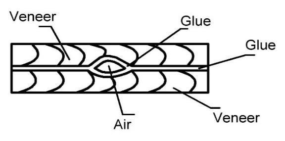
The research is based on the free oscillations method. Veneer layered composite materials are solid patchy material that consists of two or more components with clear border between them (BEKHTA et al. 2009). In the case of bundle defect presence, the area with defect can be presented as two layers, fixed on the edges with air bubble between them. Figure 1 shows formalized image of such defect. Considering upper and lower areas of a defect as a package of absolutely solid bodies with linear springy and viscous elements of the panel, the model of bundle defect can be obtained.
Fig. 1 Section of composite materials region with defect (air layer).
Figure 2 shows rheological model of veneer layered composite materials area. Each area of composite materials defect with mass m is characterized by elasticity: ��⋅�� �� (1)
where: С is elasticity of composite materials rheological model (CMRM) element [N/m], Е is elasticity modulus of CMRM element (Pa), S is area of CMRM element section (m2), l is thickness of CMRM element (m). Mass of the panel is equal to: �� =��⋅��⋅�� (2)
where: ρ is CMRM element density (kg/m3). ��1 ��2 (3)
where: �� is a coefficient, characterizing the viscosity of the panel, s-1 , A1 and A2 are amplitudes of CMRM element region oscillations [mm].
Such representation of defect model allows to suggest that shock influence on the composite materials will cause the acoustic oscillations with form and amplitude depending on the composite materials structure (BEKHTA et al. 2015, BEKHTA et al. 2016). Analysis of such oscillations spectrum at different areas of composite materials will allow to locate the defect.

Fig. 2 Veneer layered composite material rheological model.
RESULTS AND DISCUSSION
Plywood defect model allows to calculate the resonance properties of the defect and parameters of measuring device parameters to control such defects. For bundle defect and
shock acoustic method such parameters are resonance frequencies of defect elements oscillations amplitude and damping of oscillations.
It is also necessary to calculate the impact force of measuring device hammer (Fig. 3) on the controlled region. Hammer must not damage the controlled material and have sufficient energy to cause oscillations inside the plywood which can be measured by the sensor with needed accuracy. For example, the strength of undamaged pine tree wood while compressing along the fibres is equal to 40 MPa. With the force directed across the fibres the strength does not exceed 6.5 MPa. Inhomogeneity of wood structure and presence of defects significantly (up to 30%) reduces compressive strength of wood. According to this, the impact force on the composite materials surface must not exceed about 4 MPa (LAGAŇA and ROHANOVÁ 2014).
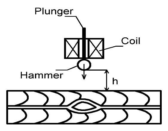
Fig. 3 The scheme of non-destructive testing device.
Metal hammer with mass m and rigidly connected with piezo is held at the height h over the plywood surface by the electromagnet. After turning the electromagnet off, it fell with acceleration a on the tested region of plywood. After the impact electrical charges proportional to the collision impulse appeared on the piezo. Hammer movement can be described by the following equation:
−���� =��ℎ�� (4)
where: �� is elasticity of plywood, (N/m), x is value of plywood crimp (mm), mh is mass of hammer (kg), a is acceleration of hammer (m/s2).
Solution of this equation (4) with initial conditions x(0) = ��0= 0 presented in (PANOVKO, 1991) can be written, as:
��0 ��
⋅���������� where �� is coefficient that can be calculated: �� �� =√�� (5)
(6)
According to this maximum, the maximum force of plywood compression will be equal to:
�������� =��⋅�������� =��0√��⋅�� (7)
where ��0 is oscillating speed, (m/s).
Placing the hammer at the altitude h = 0.1 m its speed in the moment of contact with the surface will be:
�� =√2��ℎ =√2∙9.8∙0.1=1.4(��/��) (8)
For approximate calculation of maximum impact strength, following values were applied: mass of the hammer m = 0.05 kg, wood elasticity modulus E = 10 000 MPa, defect section area S = 0.0001 m2 , defect length l = 0.2 m.
Substituting these values into equation (7) we will obtain: �������� =��∙√��∙E∙ S l =1.4∙√0.05∙10000∙106 ∙ 0.0001 0.1 =990(Pa) (9)
Calculated value of plywood compression is much less than the strength of wood (0.000990MPa << 4MPa) that guarantees the non-destructive testing of plywood by the selected method when using hammer with parameters described above.
After the impact the controlled region, presented as the thin plate, this will compress and transfer the speed to the neighbouring region (BABAKOV 1968). Elasticity forces that occur in the plate will deform the next layer. Elasticity forces of the second layer will stop the first layer and the second layer will get the speed. In such case the first layer will stop and the second layer will start to move and compress. Layer deformation will move across the plywood. This phenomenon is called the elastic wave that moves the initial impulse through the plywood panel.
There are different types of elastic waves: longitudinal (compression and stretching) lateral (offset waves), flexural, surface longitudinal (Rayleigh waves), surface lateral (Lyav waves) according to BABAKOV 1968. Inside the plywood flexural waves will prevail because the thickness of material is much smaller than the length of elastic wave that spreads inside.
Measurement device hammer transfers the kinetic energy to the regions of controlled material and changes their inner energy. Material areas kinetic energy density inside the elastic wave is equal to: ���� = 1 2 ∙��∙��2 = 1 2 ∙��∙��2 ∙��2(J) (10) where: ω is circular frequency of oscillations[1/s].
For entire panel it will be equal: 1 2 ∙��∙��2 ∙�� = 1 2 ∙��∙��2 (11)
where: V is panel volume [m3].
Kinetic energy obtained by the plywood is proportional to the kinetic energy of the hammer and depends on its mass and speed. Measuring the oscillatory speed v of plywood panel, there is possible to make decision about its mechanical properties and presence of inner defects.
Oscillatory speed can be obtained from the differential equation of oscillations: ��4�� ��(����4 +2 ��4�� ����2����2 + ��4�� ����4)− ��ℎ��0 2�� �� =0 (12)
where: �� = ��ℎ3 is cylindrical rigidity of the panel in bending (kg/m), 12(1−��) x, y are coordinate axes, f0 is own oscillations frequency (Hz), g is free fall acceleration, �� is specific weight of plywood, (kg/m3). Longitudinal and transverse oscillations are related both through motion equations and through boundary conditions. For low-frequency oscillations, transverse movements exceed longitudinal ones. Transverse and longitudinal oscillations can be considered
separately, ignoring the relationship between them. In this case, an anisotropic beam can be considered as isotropic. In addition, the task was to find the approximate frequency domain of the sample oscillations. The exact values of oscillations were found experimentally. Therefore, this formula was used in the work (TOVSTIK 2014).
Solution of equation (12) defines the oscillations form that depends on boundary conditions. During the oscillations the surface of panel is divided by the nodal lines ωi (x, y) = 0 into the regions where the oscillations will be in the same or in the opposite phases.
Uniformity of composite materials surface properties will be ensured in case the node lines cross the surface only at the edges and nowhere else (AYDIN et al. 2017). Therefore, ωi(x, y) = 0 only along the lines x = 0, x = a, y = 0, y = b. Here, а and b are dimensions of the panel along the x and y axis accordingly. These conditions can be fulfilled in the case when the plate is fixed on all four edges that corresponds to the case when the plate is located over the defect. Forms of oscillations for plates with equal areas in the defect position with the given border conditions can be written down as:
∙������������ �� (13)
where: Ai j is oscillations amplitude [m].
The first part of equation 13 never becomes equal to zero inside the plate and only on the edged ω11(x, y) = 0. Therefore, the nodal lines do not cross the plywood region surface and all elements will oscillate according to the following equation:
��(��,��,��)=��11 ∙������(��,��)∙�� ∈(����+��)=��11 ∙������(����+��) (14)
Plate regions will simultaneously displace into the same direction reaching the maximum displacement values and simultaneously pass through the equilibrium position. This is the first own oscillation of the panel. Its frequency can be determined from the equation (BARANOVA 2015):
��01 =��2 ∙(
1 ��2 + 1 ���� ��2)∙√��ℎ (15)
Such oscillations will fade during some period of time. The dissipative forces related to the fastening points and the environment resistance are considered to be the reason of damping. The oscillations energy is spent to overcome this resistance that results in decrease of oscillations amplitude peak values (BARANOVA, 2015). Peak values can be obtained from equations:
��1 =����
−���� (16)
��2 =����
−��(��1+��) (17)
where: t1 is the time of the first biggest displacement (s), η is plate viscosity coefficient, �� = √ 2�� ��2+��2 is period (s).
Coefficient η can be obtained from the logarithmic oscillations decrement equation: �� =���� =����
���� ����+1 (18)
Considering the supports inelastic the equation of forced oscillations after the influence of outer force F(τ) can be written as follows:
��2�� ����2 +2�� ���� ����
+��0 2�� = where: F (τ) is force that acts on the panel (N), τ is impact duration (s). Common solution for equation (19) is: 1 ����0
∫ ��(��)��
�� 0 ∙��������0(��−��)����
where ��0 =√��0 2 − ��2 . (19)
(20)
Experiments showed significant difference of spectrum parameters of piezo output signals in the case of presence and absence of defects in the controlled area. Experiments were performed on the samples of five-layer plywood with the thickness of 7 mm (Fig. 4).
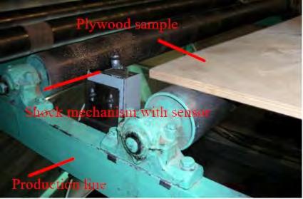
Fig. 4 Approbation device for defect control.
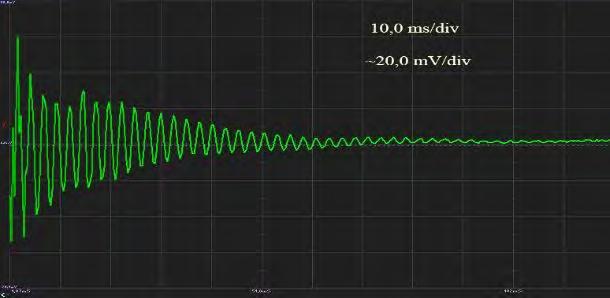
As the sensor was used a piezo-element with diameter 10 mm and thickness 1 mm, rigidly fixed on the hammer and electrically connected to the digital oscilloscope OSCILL (PINCHEVSKA, 2019). Oscillograms in Figure 5 show the output signal from piezo sensor in the region without defect. Oscillograms in Figure 6 show the output signal from piezo sensor in the region with defect. Both oscillograms allow to draw following conclusions: in the case of hammer impact on the surface of non-defective area resonates the whole panel, oscillogram has one resonance peak (Fig. 5, b) and oscillations have the form of damping sine (Fig 5, a);
a) b)
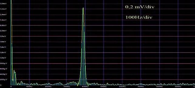
Fig. 5 Oscillograms from non-defective region.
in the case of hammer impact on the surface of non-defective area different regions resonates so additional resonance peaks occur (Fig. 6, b);
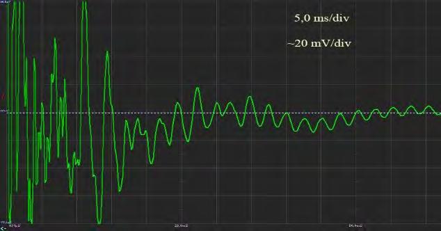
a) b)
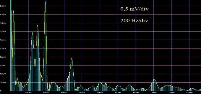
Fig. 6 Oscillograms from defective region.
controlling the number of resonance peaks it is possible to locate the defects inside the plywood.
The given mathematical model explains the occurrence of acoustic oscillations of different shapes under the influence of the shock method. The compression index of plywood (990 Pa) is calculated, which is much less than the strength limit of wood (4 MPa), which will guarantee a non-destructive testing. Mathematically substantiated the magnitude of the output signal of the piezoelectric element, which is affected by: the mass of the plywood, which interacts with the impact of the drummer; the force F with which the drummer acts on the surface of the plywood; oscillation frequency and viscosity.
Factors influencing the output signal are the depth of the defect, its location in the sample and the area of the defect. The research was carried out on defect-free and defective areas of plywood. Regression analysis of the influence of the defect characteristics on the parameters of the output signal of the shock sensor showed that the number of pulsations is affected by all factors almost equally; the frequency of free oscillations is most influenced by the factor of the location of the defect, which is positive for control, but is not sensitive to determine the area of the defect; the coefficient of harmonic distortion is most affected by the area of the defect, while other factors have little effect, which makes this parameter the most accurate for control. So, controlling additional parameters will allow further increase the accuracy of defect detection.
CONCLUSIONS
Proposed rheological model includes mass, elasticity and viscosity of each veneer layered composite materials component: veneer, glue and air. Such model explains the appearance of oscillations with different form after the shock influence. The analysis of the hammer sensor oscillograms shows that when the hammer of the measuring instrument is exposed to the plywood, if there is no defect, the whole area of the sample begins to resonate. There is one resonance and the oscillogram has the form of a sinusoid falling in amplitude. When the hammer is operated as a measuring device on area of the defective plywood, different areas of the sample begin to resonate. Moreover, resonances appear in the range of the piezoelectric sensor. The number of resonances, the character of the layering and its place on the sheet of plywood can be assessed. Therefore, that in the case of a stratification defect, the integrity of the material is broken and two or more elements appear in the defect area, which have their spectrum of resonance frequencies. The analysis of the reaction of the section of the controlled material to the impacts was carried out to determine the characteristics of electrical signals on the piezoelectric sensor during the detection of defects.
REFERENCES
AYDIN, I., DEMIRKIR, C., COLAK, S., COLAKOGLU, G. 2017. Utilization of bark flours as additive in plywood manufacturing. In European Journal of Wood and Wood Products 75(1), 2017, p. 63–69. BABAKOV, N.M. 1968. Teoriya kolebaniy. Nauka, Moscow, 1968. TOVSTIK, P.E., TOVSTIK, T.P. 2014. Svobodnye kolebaniya anizatropnoj balki. In Vestnik SPbGU, Ser.1. T.1 (59), 2014, p. 599–607. BARANOVA, O.S. 2015. Defektoskopiya kompozytnyh materialiv z zastosuvannyam udarnoakustychnogo metodu neruynivnogo kontrolyu. In Vasnyk KNUTD, No 6(92), 2015. PINCHEVSKA, O., BARANOVA, O., GORBACHOVA, O., GANDZUK, V. 2019. Research of plywood quality by acoustic methods. IOP Conference Series: Materials Science and Engineering, 2019. BEALL, F.C., BIERNACKI, J.M. 1991. An approach to the evaluation of glulam beams through acousto-ultrasonics. In 8th International Nondestructive Testing and Evaluation of Wood Symposium. Vancouver, 1991, p. 73–88. BEKHTA, P., HIZIROGLU, S., SHEPELYUK, O. 2009. Properties of plywood manufactured from compressed veneer as building material. In Materials & Design 30(4), 2009, p. 947–953. BEKHTA, P., ORTYNSKA, G., SEDLIAČIK, J. 2015. Properties of modified phenol-formaldehyde adhesive for plywood panels manufactured from high moisture content veneer. In Drvna Industrija 65(4), 2015, p. 293–301. BEKHTA, P., SEDLIAČIK, J., SALDAN, R., NOVÁK, I. 2016. Effect of different hardeners for ureaformaldehyde resin on properties of birch plywood. In Acta Facultatis Xylologiae Zvolen, 58(2), 2016, p. 65–72. PANOVKO Y.G. Vvedenie v teoriyu mekhanicheskih kolebanij. Nauka, Moscow,1991. BOBADILLA, I., DE HIJAS, M.M., ESTEBAN, M., ÍÑIGUEZ, G., ARRIAGA, F. 2009. Nondestructive methods to estimate physical and biological aging of particle and fibre boards. In Proceedings of the 16th International Symposium on Nondestructive Testing of Wood. Beijing, 2009, p. 222–228. BUCUR, V. 2011. Delamination in wood, wood products and wood based composites. Springer Netherlands. 2011, 401 p. eBook ISBN 978-90-481-9550-3. DILL-LANGER, G., BERNAUER, W., AICHER, S. 2005. Inspection of glue-lines of glued-laminated timber by means of ultrasonic testing. In Proceedings of the 14th International Symposium on Nondestructive Testing of Wood. Eberswalde, 2005, p. 49–60. DIVOS,F.,SZALAI,J.,GARAB,J.,TOTH,A. 2009. Glued-laminated timber evaluation. In Proceedings of the 16th International Nondestructive Testing and Evaluation of Wood Symposium. Beijing, China, 2009. p. 287–293. ILLMAN, B.L., YANG, V.W., ROSS, R.J., NELSON, W.J. 2002. Nondestructive evaluation of oriented strand board exposed to decay fungi. In Proceedings of the 33rd Annual Meeting of the International Research Group on Wood Preservation, Cardiff, 2002, 6 p. LAGAŇA,R.,ROHANOVÁ,A.2014. Prediction of modulus of elasticity using acoustic characteristics. In Acta Facultatis Xylologiae Zvolen, 56(1), 2014, p. 5–12. ROSS, R.J. 2015. Nondestructive evaluation of wood: second edition. Madison, WI, Forest Products Laboratory, 2015, 169 p. SANABRIA, S.J., FURRER, R., NEUENSCHWANDER, J., NIEMZ, P., SENNHAUSER, U. 2011. Monitored assessment of structural integrity of multilayered glued laminated timber beams with air-coupled ultrasound and contact ultrasound imaging. In: Proceedings of the 17th Symposium Nondestructive Testing of Wood, Sopron, 2011, p. 359–366.
SANABRIA, S.J., MUELLER, C., NEUENSCHWANDER, J., NIEMZ, P., SENNHAUSER, U. 2009. Aircoupled ultrasound inspection of glued solid wood boards. In Proceedings of the 16th International Nondestructive Testing and Evaluation of Wood Symposium. Beijing, China, 2009. p. 281–286. STROBEL, J.R.A., DE CARVALHO, M.A.G., GONÇALVES, R., PEDROSO, C.B., DOS REIS, M.N., MARTINS, P.S. 2018. Quantitative image analysis of acoustic tomography in woods. In European Journal of Wood and Wood Products 76(5), 2018, 1379–1389. WEN,J.,LI,Z.,XIAO J. 2020. Noise removal in tree radar B-scan images based on shearlet. In Wood Research 65(1), 2020, p. 1–12.
ACKNOWLEDGEMENT
This work was supported by the Slovak Research and Development Agency under the contracts No. APVV-16-0177, APVV-17-0583, APVV-18-0378 and APVV-19-0269. The authors thank VEGA project No. 1/0556/19.
AUTHOR’S ADDRESS
Prof. Ing. Olena Pinchevska, Dr.Sc. Olha Baranova, Ph.D. Valentyn Golovach, Ph.D. Yuriy Lakyda, Ph.D. National University of Life and Environmental Sciences of Ukraine Department of Wood Processing vul. Geroiv Oborony 15 Kyiv 03041 Ukraine Opinchewska@gmail.com olhabaranova@nubip.edu.ua vale_go@mail.ru yuriy.lakyda@gmail.com
Prof. Ing. Ján Sedliačik, PhD. Technical University in Zvolen Department of Furniture and Wood Products T.G. Masaryka 24 960 01 Zvolen Slovakia jan.sedliacik@tuzvo.sk
Mykola Vasylenko, Ph.D. National Aviation University Department of Aviation computer-integrated complexes Liubomyra Huzara ave. 1 Kyiv 03058 Ukraine m.p.vasylenko@nau.edu.ua
Prof. Ing. Konstantin Shevchenko, Dr.Sc. The National Technical University of Ukraine "Igor Sikorsky Kyiv Polytechnic Institute Faculty of Instrumentation Engineering Department of automation of experimental researches Borschagovskaya street 126 Kyiv 03056 Ukraine autom1@meta.ua


