
32 minute read
Case study 23 Comment Inventor in the AEC world


MicroStation at the heart of LiDAR surveying solutions
Blom Aerofilms meets the challenge posed by a growing need for rapid, accurate, and cost-effective surveying and mapping to support GIS analysis and civil engineering design applications
Blom Aerofilms is a leading provider of aerial photography and digital map solutions for civil engineering design, environmental assessment, and land information management. According to Chris Gaunt, business development manager at Blom Aerofilms, “We have a reputation as an innovative company. We actively embrace new and highly efficient surveying techniques and technologies so that we can operate more quickly with fewer staff. That is why over seven years ago we took a strategic decision to adopt airborne light detection and ranging (LiDAR) as a core technology, supported by a full range of data processing services.”
To do this, Blom Aerofilms chose the MicroStation-based Terrasolid integrated software suite to process laser data points, adjust trajectories, create surface models of the ground, and to rectify images to orthorectified photographs.
Some years ago, the company foresaw a growing need for rapid, accurate, and cost-effective mapping to support GIS analysis and civil engineering design applications. “Since conventional surveying techniques were time-consuming and labourintensive, our challenge was to find a fast and efficient solution,” Gaunt explained. “LiDAR met our needs exactly. Combined with digital photography, it enables us to map large areas of urban and rural landscapes in three dimensions. It also helps us to keep staff off the infrastructure corridor: working on motorway hard shoulders is highly dangerous and track possession whilst surveying rail infrastructure is costly and disruptive to schedules.”
Blom Aerofilms was formed in 1919 as Aerofilms, with Simmons Mapping being formed in 1965 and acquiring Aerofilms in 1997, becoming Simmons Aerofilms in 2001. It is now part of the 1,000-strong Oslo, Norway-based Blom Group. Said Gaunt, “As part of the Blom Group, we have access to 22 aircraft and eight digital cameras, as well as fixed wing and helicopter mounted scanners.” The company’s client list includes the Environment Agency, the Highways Agency and the national mapping agen¬cies of the United Kingdom, Belgium, Denmark, and a number of Caribbean countries.
How LiDAR works
Both helicopter and fixed-wing LiDAR systems scan the surface below the aircraft collecting considerable information on the terrain, achieving height accuracies up to 40mm. Depending upon the system, the scan rates can vary from 50,000
3D DEM (Digital Elevation Model) intensity values of M25 motorway
to 100,000 pulses per second, producing a dense cloud of three-dimensional points. The resultant data is loaded into MicroStation and various Terrasolid modules are used to process the data, displaying the results in MicroStation. Every point captured is geo refer¬enced and time stamped, and laser journey times are used to compute distances.
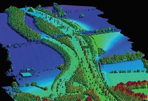
Hamish Grierson is CAD manager at Blom Aerofilms and is responsible for ensuring that the data process¬ing technology delivers high-quality results on time and within budget. Outlining the process, Greirson said, “Typically, we split projects into areas of around 300 metres by 200 metres, each one of which contains around 1.5 to 2 million LiDAR points. We classify the points as ground level, low vegetation level, me¬dium vegetation level, or high vegetation level. We then create a surface, triangulating all of the points classified as ground.”
He explained, “We can add as many classifications as we want, assigning colours to indicate these different classes. The high vegetation and the ground are the most useful levels because that gives a good indication of trees and buildings as well as the ground. If required, we can also use a com¬bination of traditional land surveying of road edges and aerial photography infill.”
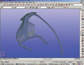
The Crystal film

Greirson continued, “We operate two LiDAR systems, both of which ultimately depend on MicroStation. We use the Optech fixed-wing system from Blom Geomatics in Norway and initially we used the TopEye helicopter-based system from Blom Sweden.” The Mark 2 version of TopEye collects over 50,000 points per second, to a high degree of accuracy. It can be flown at low altitudes and has an excellent ability to penetrate vegetation, producing point densities of up to 20 points per square me¬ter, enabling large scale topographic surveys to be undertaken.” As Greirson pointed out, “The Terrasolid developers made a deliberate decision to use MicroStation because of its capabilities and it is now the graphics engine of choice for LiDAR processing.”
Greirson recalled, “Adopting LiDAR, we initially installed one seat of Terrasolid and one seat of MicroStation, increasing this to eight seats as we won more and more contracts. Up to that point, we’d only ever used AutoCAD. True, we had provided mapping to a major rail client in MicroStation DGN format, but we had done this by converting from AutoCAD DWG format.”
Greirson explained, “In MicroStation V8, Bentley has extended the DGN database to include AutoCAD DWG element types, providing AutoCAD DWG support at the platform level. Because of this excellent support for native DWG, it doesn’t really matter if the client is using MicroStation or AutoCAD or both.” However, for Greirson, “I have absolutely no concerns at all about running a mixed environment, and we are now finding that more and more clients are asking for MicroStation deliverables.”
Greirson continued, “The way in which MicroStation works is of great benefit to us. To ensure high performance, the large amounts of LiDAR data - often many gigabytes - are held in virtual memory at this point and only saved in MicroStation DGN format once processing is complete.” He continued, “Visualisation and animation is built in to MicroStation as standard and you can attach different line styles to
Above: Eurocopter AS 350 B - TopEye Mk II LiDAR system collects 50,000 points per second, to a high degree of accuracy.
Right: DTM (Digital Terrain Model) of land slippage A66 Crackenthorpe.
3D DTM (Digital Terrain Model) shaded relief of M25 motorway
the 3D representation as an aid to un¬derstanding and interpretation. Creating dynamic 3D fly-throughs is simple and intuitive. Just create the flight line, press the button, and MicroStation does the rest – no extra software required.”
Blom Aerofilms has completed a number of large-scale and high-profile LiDAR-based projects including a full survey of London’s M25 motorway including all carriageway and ‘stubs and tails’, totalling over 250 miles or 1,500 line-miles of data. The project was flown at only 100 metres using helicopter-based LiDAR for vegetation penetration and high accuracy. Gaunt is certain, “We clearly made the right decision to invest in LiDAR at an early stage. We are an established player with many successful projects to our name and there is no longer any need for us to sell the benefits of the technology. Through investing in technologies such as LiDAR, we are increasing our competitiveness and we are adding value for our customers. We could not do this without MicroStation.” www.bentley.com
www.terrasolid.com www.blompictometry.com

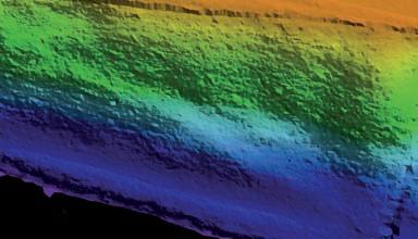

M25 3D DEM (Digital Elevation Model) shaded relief of M25 motorway
Wooden it be nice
The use of Robobat FE software at Structural Engineers evolve has enabled optimised design of laminated wood structures, writes Nick Lerner.
The aesthetic beauty of laminated wood is only part of its appeal. As the sole renewable construction material wood reduces building owners’ carbon footprints with the added bonus of enhanced design options. Because of its almost endless design possibilities an FE based 3D frame analysis programme is a must. One Structural engineering consultancy that is pioneering the use of laminated wood in mainstream and alternative construction is Evolve of London and Glasgow. The company has been using Robot Millennium FE software from Robobat for six years and has recently been working on new-build retail stores and innovative structures in timber around the UK. Mark Sinclair, Associate at evolve, described how Robot Millennium is used in this application. “Our work in this sector has been in conjunction with Tesco and other major retailers that are introducing measures to reduce their carbon footprint in new buildings by specifying laminated timber rather than steel in the building frame. Robot allows design and analysis of 3D frames to be created that incorporate different materials i.e. steel & timber and accommodates their properties. This optimises the use of materials and allows the substitution of steel members within the standard 18.0m x 12.0m grid for timber with the minimum of effort. Aside from the structural engineering data that the software produces, one of the significant advantages of using Robot has been the output of material quantity and specification report schedules that we pass on to our suppliers and others in the supply chain. These reports which would be time consuming to produce manually are generated automatically by the software as the design develops allowing us and other stakeholders to understand the cost and quantity implications of design variations at an early stage.”
Using Robot Millennium, evolve designed the timber frame for Tesco’s eco-store in Wick, Scotland. This was the UK’s first sustainable supermarket, following this they worked on the second in Shrewsbury, England, and are now designing other timber-framed projects around the country.

Branching out
Mark Sinclair continued, “We use Robot Millennium to calculate stability analysis for vertical and horizontal bracing, applying wind loads and other project specific loadings to the main structure and its component details. Having calculated the deflection of long span elements and designed their fixings, the automated quantity report scheduling is a real time saver that allows us to spend our time very productively. The software allows us to optimise designs speedily and produce solutions that use optimal amounts of material - no more and no less. Wood gives us many more fixing possibilities than steel and we have developed systems for temporary and removable fixing to make the construction process far simpler. For example, we can fix frame elements temporarily and put them in position before permanent fixings are used. Robot is used to calculate the extent to which this methodology is practicable, and also allows us to look at alternative design options within this technique.”
The ability to optimise a design and its construction methodology often leads to more elegant solutions with greater visual appeal to shoppers as well as a positive impact on the owners’ carbon footprint.
Accurate deflections and reactions of the Timber Wall.
100% Detail Exhibition (Earls Court, London 2007) - Involved timber structure.
Leaves the past behind

It is likely that as more companies realise the environmental benefits of laminated wood in their buildings the market will adapt to meet demand. evolve plans to capitalise on this trend and has been working to secure its already strong position by exploring the potential of optimising designs with Robot Millennium.
Mark Sinclair explained, “While the design of a supermarket to a pre-existing grid plan presents several technical design and methodology challenges, the creative design element is relatively straightforward. This is not the case with other projects where innovative design is at a premium and new ways must be found to ensure structural integrity.
“Because laminated wood is easy to shape and bespoke cross-sections are easy to fabricate, the achievable design possibilities are endless. One of the


advantages of designing for this material using Robot is knowing, in real-time, whether a design will work in practice while having a fully reported understanding of the cost implications of design modifications.
“We can import 3D models into Robot from other CAD systems, such as such as AutoCAD, Digital Project, or MicroStation, or produce designs using the system’s own modeller. Either way, we are assured that the software verifies our design options and choices for final construction in the knowledge that they cannot be bettered from a technical standpoint.” Seeds of change A recent project for FinnforestMerk, designed in conjunction with Alsop Architects, involved evolve producing finished designs for an exhibition stand using LVL Timber Wall. Taking an original Alsop design and adapting it for construction without any loss of design intent was crucial for this industry showpiece. It was important to retain the dramatic double waveform while ensuring full structural integrity and material optimisation. Since the project was produced to the tightest of deadlines evolve took a copy of Robot software on site to the exhibition and ran Frame Analysis calculations on a laptop computer as the waves were built. Throughout this process new calculations were made and appropriate modifications developed for the construction. evolve has certainly not left steel & concrete behind and uses Robot Millennium every day in its structural design work for a range of projects. The company has recently worked on steel designs for Gatwick Airport and T5, Tottenham Hale Retail Park and concrete structures at Thomas Cubitt’s former
Tesco Wick First Timber Supermarket in the UK – modelled for material quantities for quick and accurate
procurement.
Wren Park, Torquay (Kier Northwest 2004) - Modelled for movement during different construction stages. Calculated deflection was within 2mm of the actual on-site deflection.
works, Grovesnor Dock in Chelsea. “But” says Mark Sinclair “ While traditional steel and concrete construction forms the majority of our work, the use of laminated wood is fast growing, not just in retail, but also in other commercial and domestic construction. Laminated wood offers so many design options that it effectively gives a new palette to designers. As seen in our supermarket projects it makes a very interesting alternative to steel and in other applications the design freedom and restraints that it presents are very exciting. There is no stopping a fashion once it gets started and laminated wood is very much in vogue right now.
“Since a great deal of the appeal of laminated wood is the reduction of carbon usage that it offers, it makes sense to optimise its design and so generate further savings through efficient use of resources. Our use of Robobat’s Robot Millennium in the design process allows us to reduce material quantities by optimisation, develop new construction techniques that save both labour and energy, and keep track of costs throughout. When these factors are added to the ease of producing verified designs that are right first time, the appeal of using Robot Millennium, as we do, is significant.”
www.robobat.co.uk www.evolveuk.biz


Inventor in the AEC world?
Earlier this year, directors of the AEC specialist, CADline, acquired the manufacturing solutions reseller Midas Technology. We asked Paul Watson of Midas if this move reflects a general trend for architects and suppliers to work together more closely and how using Autodesk Inventor can help
It all comes down to business. On the one hand there’s a growing number of huge design and construction projects presenting a myriad of opportunities. But on the other, there’s intense global competition, customers becoming increasingly discerning and sophisticated, the need for environmental compliance and an ever-strengthening demand for projects to be built not just better – but much faster too.
In this environment, every company is searching for ways to become more agile and responsive. Many have found that encouraging different disciplines to work closer together – either in-house or as multi-organisation project teams – is a key factor to progress in this area.
Improved communication between professionals brings better understanding and empathy, resulting in buildings which retain their design integrity. It provides synergies and economic benefits through materials and supply chain efficiencies. But, importantly, it also presents a united, organised and confident profile to the client - which is more likely to lead to repeat business.
Because of the continuing growth of globalisation and remote working, closer relationships in the traditional sense can prove difficult. But, from our experience, these are increasingly being played out in a virtual world as much as in the real one.
As a result, we are detecting a growing interest from AEC professionals in Autodesk’s 3D manufacturing solution, Inventor. Demand is particuarly strong from multi-disciplinary organisations or prime contractors on projects such as universities and schools, office buildings, retail spaces or even private homes and yachts where fittings and furnishings are integral to the design.
Testing and analysis
So what advantages are there to creating products, from mouldings to customised furniture, in Inventor rather than AutoCAD? For a start, it enables designers to develop new concepts in 3D which are frequently a challenge in 2D, enabling more elegant solutions to the difficult spatial problems often encountered on these projects.
It also provides them with the technology to assemble, analyse and test designs. Suppose, for example, a designer was creating a revolving door as an entrance to a hospital. Simulation and stress analysis tools will enable them to develop a digital prototype to ensure the revolving mechanisms all function correctly and test it on screen.
Accurate bills of materials can be created early on in the design so that those responsible for purchasing can get a head start, particularly on components with a long lead time. Engineering data can also be sent to fabricators on the shop floor and installers in the field to let them know what to expect.
Autodesk Inventor Suite is a particularly good choice of manufacturing software for the construction industry because it also includes the latest version of AutoCAD Mechanical. This means a familiar environment for those using AutoCAD Architecture. It also enables firms to continue to use and leverage existing 2D AutoCAD DWG data, while collaborating with all the project team.
But perhaps more importantly in this context is the freedom Inventor gives designers to share models, drawings, data and other documents with users of other Autodesk applications such as Revit Architecture by using DWG TrueConnect.
This will bring those designing building components in Inventor closer to architects using AutoCAD, AutoCAD Architecture and Revit as well as those in the supply chain using AutoCAD. With DWG TrueConnect, what the designer sees using Inventor is exactly the same as what their supplier will see when they open it in AutoCAD.
By establishing this mutual, seamless link,
With a revolving door designed in Inventor, simulation and stress analysis tools could then be used to develop a digital prototype to ensure the revolving mechanisms all function correctly.


Sweeping staircase drawings produced from Inventor model.
the two systems become interoperable and users can review their work, checking for clashes and for continuity of design.
Inventor uses DWG as the standard for its drawing storage and Inventor-created DWG files can be read in AutoCAD (whether it’s vanilla, Mechanical, Electrical or Architecture or even LT) and Revit without any translation or conversion. Inventor stores the individual drawing views as separate entities, so from within AutoCAD, designers can use the Design Centre to open an Inventor DWG file, browse its contents (in terms of drawing views) and just extract the view or views they need for re-use inside AutoCAD.
What’s key here is that the drawing views extracted and re-used within AutoCAD are associatively linked back to the originating Inventor DWG file, so updates can be propagated quickly and efficiently.
DWG TrueConnect the fastest way for an Inventor user to create DWG data for sharing. It’s also the simplest way to incorporate this data into 3D models. Using the standard File Open command in Inventor, they can simply browse to any native DWG file and then open it directly.
They can pan, zoom, print and measure in Inventor without issuing a single AutoCAD command. They can also easily copy and paste 2D geometry into an Inventor Sketch without ever opening AutoCAD or going through multiple dialogue boxes. Unlike rival 3D modellers, Inventor can also respect geometric and dimensional constraints automatically.
Those needing to circulate drawings to non-CAD using personnel including clients can also accelerate review processes with Autodesk Design Review. This enables any team member without the original creation software to accurately measure, redline and annotate DWF, DWG and DXF files and communicate changes in the context of the design.
They can also track status and drag and drop information of any type including product specifications, change orders or estimates, combining them into a single file. The DWF file can then be round-tripped to any Autodesk application, overlaying digital mark-ups onto the original CAD file for fast revisions.
As design work becomes more collaborative, we are becoming increasingly aware of the value that manufacturing solutions such as Inventor can give to architects, furniture designers and other professionals in the construction industry.
But it is within the communication between professionals and their applications that the real advantages of interoperability will be won or lost.
www.cadline.co.uk / www.midastechnology.co.uk
Beyond 3D
Allies and Morrison Architects Stephen Griffin and Paul Eaton have evaluated Gehry Technologies Digital Project 3D BIM software on several recent design projects. The results so far experienced have been better design productivity, enhanced creativity and the promise of other benefits further down the line, writes Nick Lerner.
Allies and Morrison is an architectural practice that has experienced tremendous success developing solutions for a wide range of high profile clients. For three years the company has been running its projects in 3D. Initially the team reviewed the 3D solutions on offer in the AEC space in relation to their needs as a very busy architectural business where time is always limited.
Their investigations revealed that there are tools marketed to increase design productivity, capture creativity and control supply chains. Those three requirements are crucial to Allies and Morrison and needed to be reflected in the evaluation process. It was also considered that a system based on a Building Information Model (BIM) would bring the advantages and benefits of the latest technology to their practice. Following a thorough evaluation they selected Gehry Technologies Digital Project software (DP) supplied in the UK by Desktop Engineering.
Benefits are considerable
The initial evaluation process applied DP methodology to two buildings in London, 120 Moorgate and a mixed housing and retail development at Elephant and Castle. The architects wanted to consolidate their hard won knowledge on real cases. There is a sometimes-painful learning curve before real benefit derives from using DP, but once the system and its associated methodology is fully grasped the benefits are considerable.
The evaluation team found that the most satisfying aspects of using DP are the ability to iterate designs very quickly and generate reports automatically - these being updated as the design develops. Equally, the ability to change the design driven from MS excel spreadsheets is a real benefit. In practice, this allows the design team to alter gross areas and attribute relationships while automatically satisfying the reporting and design needs of developers, planners and other interested parties.
These software features are enabled through parametric algorithms that allow the coordinates of attributes to be maintained in relation to each other while designs iterate. This gives the advantage that features do not have to be re-designed to accommodate design changes because attributes effectively reposition themselves automatically.
The architects claim that the benefits of building a
On 120 Moorgate Allies and Morrison were able to run 22 façade iterations - in one day.


The ability to drive the design from an Excel spreadsheet is a real benefit for Allie and Morrison.
parametric 3D model are enormous, and the more the model is ‘rigged’ with information the more benefits it delivers. Using DP enables simultaneous input from several disciplines and this is where the productivity gain starts because data on, for example, materials, planning, finance, manufacture and other factors can be added to the model before designs are complete.
Areas, plans, sections, and reports on angles, light and associated rights and compensation amounts, as well as other types of report can be generated to provide all stakeholders with the information that they need in the format that best suits them. This may be visual information in the form of rendered views, 2D output from the model or the most recent mathematic calculations related to the project as a whole.
Higher ground
The team claims that standard 3D architectural CAD software takes architects to a plateau where it is difficult to become more productive. But using DP and learning new skills it has become possible to introduce more efficient methodologies. Once the initial digital model is built it is possible to write parametric rules for each element meaning that both minor and major changes can be made quickly with all associated data being amended in real time. Further, reporting procedures traditionally slow down the design process; DP’s automatic report generators speeds it up again.
The company that supplied and installed DP to Allies and Morrison, Desktop Engineering, also provides training, support and an interface to Gehry Technologies, part of Frank Gehry’s practice. Managing Director Geoff Haines said, “DP is based on the same core design to manufacture software, Dassault Systemes Catia, used by car and plane

manufacturers including Boeing and Toyota. These companies use the most advanced design-tomanufacture software available, which Gehry Technologies continuously develops making it suitable for the AEC industry. This brings the proven benefits of large-scale design and manufacture software to architects, at an affordable price. The Building Information Model, BIM, is a complete set of data that includes 3D design and manufacturing information as well as associated rules, methods and knowledge that govern all aspects of a building or development.”
The team at Allies and Morrison found that design intent is captured in DP as a series of rules that the software maintains and applies throughout the design process. This means that conceptual frameworks stay intact throughout the many changes that the design is subjected to, and that all the while, development targets are retained and optimised.
New places to go
The 3D evaluation team also discovered that the design productivity that DP produces lead to greater flexibility and increased creativity because the software opens options that are not available from other less productive methodologies. It effectively provides new places to go, for example, the architects were able to run 22 façade iterations on 120 Moorgate - in one day. Major changes were made with no loss of design intent and with full reportability throughout. This gave the team tremendous confidence to explore and improvise.
The introduction of DP in to Allies and Morrison’s methodology has enabled the architects to respond
120 Moorgate is a 14,540 sqm (GEA) retail/office-led, mixed use development located at the northern edge of the City of London.
better to client and stakeholder needs and react to briefs with increased confidence and creativity; an example being that it has become possible to generate viable optimised and fully reported designs that it would be impossible to draw in anything other than DP. In other cases it has become possible to run cost versus aesthetic comparisons quickly and make better and more accurate decisions as a result.
While these benefits are accruing through the use of the parametric 3D digital model, others will be seen further down the line. DP has enhanced the team’s ability to communicate project status in terms that recipients need and can relate to. The same communication enhancement is available using data needed for manufacture with Numerically Controlled Machines or for generating file formats compliant with sub-contractors’ systems and other CAD programmes. Having seen the efficiencies that DP brings to the design and planning process the architects are looking forward to applying the manufacturing capability that DP carries over from the full Dassault Systemes Catia V5 PLM suite on which it is based.
www.dte.co.uk www.alliesandmorrison.co.uk


Scanning uncovered
Steve Hannath of Softcover looks beyond the marketing hype and tells you all you need to know when buying a wide format scanner for CAD.
CAD users wanting to buy a standalone wide format scanner for archiving, printing or raster to vector conversion of technical drawings and maps face a growing array of choices and confusing claims. There are two main types of scanner technology: CCD (charged couple device) and CIS (contact image sensor).
Vested interests on either side have white papers on “CCD versus CIS” explaining the superiority of their technology over the other. Depending on whose article you read the other technology is utterly unsuited to your requirements. Nothing is further from the truth. CCD technology has been in production longest and has the greatest number of users worldwide. CIS technology is newer, more affordable, growing in popularity and, despite what its CCD critics say, capable of good results, especially in monochrome.
CCD scanners are generally agreed to have a wider colour gamut, (ability to scan a wider range of colours), a higher dynamic range, (ability to capture smooth gradations of tone), and better resolving power, (ability to distinguish between closely spaced lines, etc). Generally, this makes CCD better suited to demanding professional reprographics work. Both technologies are suitable for scanning monochrome or colour technical drawings but increasingly CIS scanners are more likely to do it at a price the average CAD user can justify.
Manufacturers
There are many scanner suppliers but only a few scanner manufacturers. Contex (Denmark) and Graphtec (Japan) are the two major scanner manufacturers. Contex sells only CCD scanners while Graphtec sells only CIS models. Both are sold under other brand names: Calcomp, HP, Oce, Vidar (Contex) and KIP (Graphtec).
Colortrac (UK) is the only manufacturer to produce both CCD and CIS scanners. Colortrac recognise “the individual merits of CIS and CCD sensor technology and .... provide products optimised for technical documents or graphic arts imaging applications”. Colortrac CCD scanners are also sold under the Paradigm Imaging brand.
Image Access (Germany) offer the WideTEK 36, an OS independent, networked CCD scanner that includes a built-in PC. It is branded by Bowe Bell + Howell in the USA. Shapemakers (Australia) offer the Deskan, another unique device, a CCD scanner that scans an A0 drawing in seven A4 strips which are automatically stitched together.
Models
Contex, Colortrac and Graphtec all offer different scanner models at different prices. Within any manufacturer’s range, models are largely differentiated on the basis of one of more of the following: colour

capability (black and white only or colour), scan width, the thickness of the media you can scan, scan speed and interpolated resolution.
Specifications
Some manufacturers manipulate product descriptions and system specifications in order to gain a competitive edge.
Scan speed: No standard benchmark test exists for scan speed. As most manufacturers rate scan speed differently any straightforward comparison of their claims will be misleading.
The lower the resolution the faster the scan, so the lower the resolution used for the published scan speed, the faster the scanner appears. Colortrac publishes scan speed at 200 dpi. Contex publishes speed at “400 dpi Turbo” which is effectively 200 dpi. Graphtec publishes scan speed at 400 dpi and Image Access and Shapemakers publish scan speed at various resolutions.
Also, scan speed is influenced by the host PC specifications, especially when scanning at higher resolutions and in colour. As a rule, scanners scan faster than PCs can capture the data. An expensive fast colour scanner can be as slow as an entry-level slow colour scanner for all practical purposes.
Note that the speed of the scanner is only a small part of the overall process of scanning technical drawings.
Resolution: There are three types of resolution - optical, interpolated (often referred to as “enhanced” or “extended”) and “real”.
Optical resolution is the only resolution that means anything. It is the highest resolution that the scanner is physically capable of scanning at. Most technical drawings require to be scanned between 200 and 400 dpi optical. Most scanners today are 600 dpi optical devices with the exception of Contex scanners which are largely 508 dpi.
Interpolated resolution should be ignored as it adds no detail to a scan but adds enormously to the file size. Yet both Graphtec and Contex use it as a justification for their higher priced Plus models.
Contex recently replaced optical resolution as a measure of resolution with a value of their own choosing which they call “real” resolution. Contex argues that its “real” resolution better indicates the overall scanned image quality that their products offer. Thus you will see Contex scanners with 508
dpi optical resolution described as having “600 dpi resolution”.
Some Colortrac ads describe SmartLF Gx scanners as having 1,200 dpi optical resolution. In fact SmartLF Gx scanners scan at 1,200 x 600 dpi optical and save at 600 x 600 dpi, so they are more accurately described as having 600 dpi optical resolution.
Image Stitching: All scanners except those that use one camera, like the Contex Hawk-Eye, scan in strips and “stitch” them together. Despite manufacturers’ claims, all potentially have stitching issues and need to be calibrated from time-to-time to overcome this problem. We have seen stitching errors in scans made by scanners from all the major manufacturers - Colortrac, Contex, Graphtec and Image Access.
48-bit colour capture: Contex and Colortrac both offer 48-bit colour capture. This means that the scanner scans in over 281 trillion colours and then chooses “the best” 16.7 million colours (24-bit colour), which it saves. Image Access offers 36-bit capture (68.7 billion colours) and Graphtec 24-bit colour capture. 36-bit colour capture captures the entire range of colours that can be represented on the best quality scannable media (film transparency). Therefore the extra colours that can be captured by 48-bit capture offer no extra detail. It especially offers nothing to CAD users scanning monochrome technical drawings or drawings with only a few colours.
Scanning software
Today’s wide format scanners capture technical drawings with much the same scan quality. Paying more does not bring further benefits for most technical drawings. Any practical difference is in the scanning software.
Most scanners have TWAIN support which means they can be used with any software that supports TWAIN, such as Photoshop and Scan2CAD raster to vector conversion software. In addition to TWAIN support, scanners are usually supplied with free and/or paid-for proprietary software. There are three major productivity features to look for.
The ability to change the scan settings AFTER scanning the image. This means that the correct scan settings can be established without having to rescan all or part of the drawing.
The ability to VIEW the changes you make to the scan settings in REAL TIME as you make them. This means that you don’t blindly set scanning values without knowing the effects they will have. It avoids endless experimentation.
A good range of zooming and panning tools so that it is quick and easy to view the image in detail to make sure it has been scanned to your satisfaction.
In addition, for cleaning dirty technical drawings it is vital that you have practical simple and adaptive thresholding functions. Most scanning software offers thresholding but in some the implementation is so
Colortrac SmartLF cx40 with PC and Screen

poor it renders the function awkward or useless. Finally, there are many other features like auto paper sizing, image rotation, crop and deskew that will add to your productivity.
If you are intending to print your scans, you will probably want to use the printer you already have. Some software supplied with scanners is restricted in the printers it supports. You need to ensure that your printer is supported. Printing features to look for include the ability to print to scale, reduce, enlarge and print multiple copies. Some print software supplied with scanners includes colour matching to ensure that colours that are printed closely match colours on the original scanned document. This is unlikely to be of significance to CAD users scanning technical documents.
If you are going to do a lot of printing, consider a RIP (raster image processor). A RIP is a program that makes printing faster, more efficient and gives you more control over the printing process.
Networking
Contex has a proprietary software networking solution for almost all of its scanners. Colortrac and Graphtec do not.
Most scanners are required to run from a dedicated host PC but can be networked using WIDEsystemNET (Contex) or SCP EasyScan software
(Colortrac and Graphtec). Networking requires scanning software and/or drivers to be installed on the dedicated host PC and on every workstation.
New generation network scanners, like the Image Access WideTEK 36 with its built-in PC, make the need for a host PC redundant and can be run directly from internet browsers across a network.
Support
Some companies offer an on-site warranty. This tells us they believe in their product. Others offer return to factory (RTF) warranties that can be upgraded at extra cost to on-site or swap-out. RTF warranties require the scanner to be returned in the original large box which must therefore be stored, possibly an unwelcome encumbrance.
Conclusion
CIS scanners are suitable for scanning most monochrome or colour technical drawings to file, print or copy. CCD scanners are recommended to those for whom fine details and precise colour accuracy are main requirements.
For most CAD users a 36”, 400 dpi optical resolution, 24-bit colour scanner is suitable for scanning large format technical drawings. Happily, large format scanners today are comfortably overspecified for the needs of CAD users. However, anyone with dirty and “difficult” technical drawings is recommended to evaluate the scanning software and its overall usability with as much enthusiasm as you examine the hardware. Increasingly, it is scanning software that makes the difference in terms of productivity and the quality of results. l
All these issues and products are covered in greater detail on www.scanners4cad.com. .
