21 minute read
IoT impact


After a slow lift-off, the Internet of Things is making its presence felt in almost every aspect of the AECO industry and these technologies have already started to deliver, writes Peter Marchese, senior technical evangelist at Microdesk
The term ‘Internet of Things’ the same time, from a designer’s perspec- wide variety of systems that one might (IoT) has been around for years, tive, the exterior skins also give the build- find in a medium to large-sized construcbut like many promised tech- ing a unique aesthetic. tion project, building up a more holistic nology disruptions, it’s taken view of multiple disparate systems and some time for the concept to find its legs IoT for engineers driving more intelligent processes for and live up to the promises made for it. In civil and structural engineering, differ- owners, relating to the management and
In 2016, however, the IoT is finally ent uses are being found for IoT concepts maintenance of their properties. starting to be implemented in many dif- and technologies. They might be used, for For example, a building might have ferent industries – not least the architec- example, to improve people’s safety, par- sensors installed that take temperature ture, engineering, construction and own- ticularly when it comes to building struc- and pressure readings from mechanical er-operated (AECO) industry, which is tures and bridges based in seismic zones. equipment. If those readings start to incorporating IoT ideas and technologies Here, maintenance can be an issue. In climb, they may reach a point where an into how buildings are designed, con- the US state of California alone, there are inspection is required. With IoT technolstructed and managed. over 24,000 bridges that need to be ogies, on-site maintenance staff can be
Take, for example, the field alerted to the situation. They of architecture: here, we see buildings that use IoT principles to become more ‘trans‘‘ IoT will help to create better built may even be guided to the correct location via a 3D map or model. If parts need replaceformative’, adapting to users’ environments, using data that gives us ment, a service order might be needs based on changing inter- insight and automation that speeds up automatically generated. The nal and external environmen tal conditions. - processes and makes them more accurate whole process is more efficient, saving time and money. The RMIT School of Architecture and Design in ’’ The potential here is huge: the IoT will help to create betMelbourne, Australia, for example, is inspected. But inspectors face significant ter built environments, using data that covered in thousands of small, circular constraints — in many locales, they work gives us insight and automation that glass plates that rotate to improve interi- in small teams of two, for example, and speeds up processes and makes them or conditions, providing increased shade only spend two days a week in the field. more accurate. It can simplify workflows and ventilation. This is an innovative With intelligent sensors and devices, it and provide new solutions to hard-toapplication of IoT ideas that not only might be possible to collect and analyse tackle problems. We are still in the helps designers create more efficient data relating to the condition of these beginning stages of seeing how IoT will buildings, but also helps owners save structures through an automated, regular impact AECO projects and the industry money through energy efficiency. process. By identifying any issues, engi- itself, but it’s already started to deliver
Another innovative example might be neers could prioritise maintenance tasks on its promises. the adaptive skins on the Al Bahr Towers better and prevent future accidents. in Abu Dhabi, United Arab Emirates. In mechanical, electrical, and plumbing Microdesk helps AECO firms implement and These are reactive to the sun and dynami- (MEP), meanwhile, IoT technologies are utilise design and construction technology. The cally adjust throughout the day to man- being integrated into building environ- consultancy has 12 offices worldwide, including age sunlight and heat gain, again saving mental systems. That gives MEP engi- a recently opened office in London, UK. money through energy efficiency. And at neers the ability to track the status of the ■ microdesk.com
Al Bahr Towers feature an adaptive skin that reacts to the sun and dynamically adjusts to manage sunlight and heat gain. Architect AHR. Image courtesy of Christian Richters
A level-headed approach to BIM
Level of definition (LOD) matters because, without a clear idea of how much information is needed at each stage of a project, BIM benefits are likely to be compromised, writes Duncan Reed, digital construction process manager at Trimble
The promise of BIM is that it 1192-2:2013, many UK organisations were information it is expected to provide. To makes it possible for everyone using this US terminology. get the best out of BIM, it’s vital that noon a design and construction So there’s clearly potential here for one on the project team over- or underteam to collaborate faster, more confusion – but it’s actually pretty easy delivers on information. If they do, the accurately and with more transparency. to determine whether a project is using wider lean principles that underpin BIM
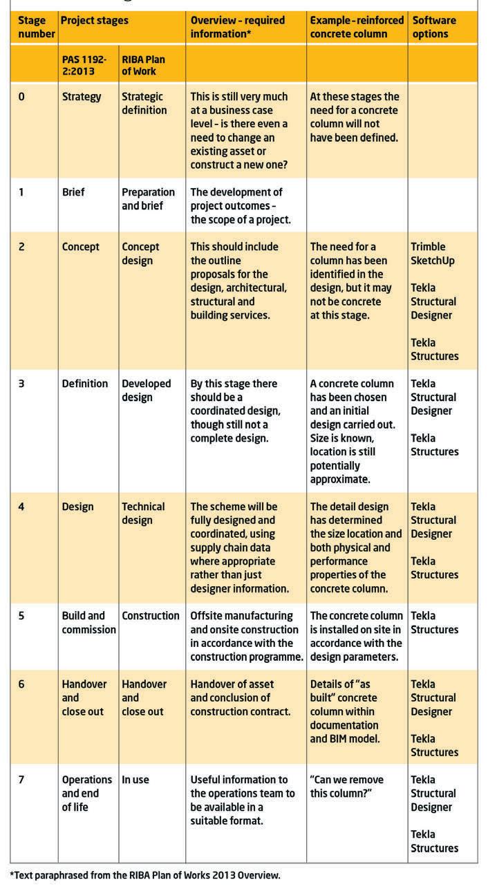
But to maximise the efficiencies BIM the UK or US definition. are unlikely to be realised. brings, each member of the project team That’s because here in the UK, LOD is This point is illustrated in the table on must clearly understand how much aligned with the Digital Plan of Work page 31, where software has been used to information is required for each different (DPoW) created by the UK BIM Task develop the information for a concrete stage of the project. Group. This provides the UK industry column; it shows the process of design-
Too little information, and risks may with an eight-stage design, construction ing and detailing a building structure not be managed effectively. Too much, and operation plan, running from zero to using BIM. and the result could be that the process is seven, and encompassing the informa- In the early stages of the project, struchampered by waste. tion requirements throughout the whole tural analysis is the most important fac-
This is where the term ‘level of defini- life of an asset. tor. By stage three, the size of structural tion’ (or LOD) comes into play – but also By contrast, the US system defines the members should have been determined where some potential confusion is intro- stages of evolving model development - — but their exact location may not have duced. LOD is a UK BIM term defined in PAS 1192-2:2013, and is used to refer to both ‘level of ‘‘ Too little information, and risks may been fixed. As the project progresses to stage four, the location of memmodel detail’ and ‘level of information detail’. (It’s worth noting that the ‘level not be managed effectively. Too much, and the result could be that the BIM bers needs to be accurately defined, along with their physical and performance properties, of model detail’ is the description process is hampered by waste as any constructability or coorof the graphical content of models at each of the defined stages. The ‘level of model information’, mean- as increasingly detailed graphical repre ’’ dination issues must be resolved at this stage. At the end of stage five, the level of while, is the description of non-graphical sentations — from LOD100 to LOD500. model definition needs to be complete. content of models at each of the stages For those who require further assis- This is the point where the structure is defined.) tance in the UK, the NBS BIM Toolkit procured from a specialist supplier; in
In essence, LOD refers to both the provides high-level guidance as to what this case, from a pre-cast concrete frame amount of graphical and non-graphical level of detail and what level of informa- manufacturer. To allow for the lean prodetail that may be required at different tion should be produced for all project cesses that BIM espouses, accurate memstages of a project, so a clear under- elements at each stage, by the various ber sizes and geometry, as well as details standing of its meaning and purpose is members of the project team. There is such as embeds, couplers and reinforceimportant. also the RIBA Plan of Works, which uses ment fabrication information are the same eight-stage approach and required and should be generated directAn important difference offers guidance on what data is needed ly from the 3D models. It’s also considerably different to the way at each stage. By adopting this staged approach to the term ‘LOD’ is used by the American develop a design and using collaborative Institute of Architects, where it refers to Managing expectations processes to share and coordinate the ‘levels of development’ and deals princi- So when a company starts on a project digital information, the project team can pally with graphical detailing in models. that is using BIM – at whatever stage of deliver much greater value and accuracy That said, prior to the publication of PAS the DPoW – it needs to know how much in a far shorter timescale.


In contrast, detailing the reinforcement required for a concrete column at stage two would be pointless, as the framing material has not been decided and the scheme may ultimately choose a steel frame solution at stage three.
It is actually very easy to produce too much information, too soon on a project, so for BIM to be used successfully, the team should define from the outset what information is important to them and when it is needed in the lifecycle of the project.
This is one of the key requirements of the Project BIM Execution Plan (BEP). In the BEP, the correct level of model definition over the life of a project should be agreed and recorded at the outset, so that all parties involved understand what they are being asked to deliver.
Using software that is capable of delivering a model to the required levels of definition is important. The Tekla suite from Trimble provides support through the eight stages of the DPoW and offers a high level of transparency for all project team members – ensuring clarity, removing the need for rework and ultimately driving waste out of the construction process.
Shake, rattle and roll
Norwegian researchers have used Comsol’s Multiphysics software to track how low-frequency sound waves travel within buildings, so that they can recommend design adjustments to alleviate annoying vibrations
Anyone who has slept near an airport knows the feeling: an early morning flight wakes you from sleep, not just because the engine is noisy, but also because everything around you seems to be shaking.
Likewise, those living near wind turbines, military sites or hospitals with helicopter landing pads often complain that windows rattle and everyday objects buzz when there is external noise. More puzzling for them is the fact that, even when they can discern no sound with their own ears, they may still notice irritating vibrations.
That’s down to infrasound: sound at a frequency of 20 vibrations per second (20 Hz) or less, not typically audible to the human ear, but with other, easy-todetect effects. As waves hit windows, spread to the floor and impact internal walls, they induce a noticeable indoor vibration. In fact, low-frequency sound waves are notorious for their potential to disturb and annoy.
Low-frequency sound waves Noise is part of modern life and there are formal standards that use sound pressure level measurements to recognise high-frequency sound waves at levels of sensitivity, intrusion and danger for humans.
According to Finn Løvholt of the Norwegian Geotechnical Institute (NGI), the creation of building vibration due to infrasound is an area of research that has not been explored extensively. For this reason, NGI, an international centre for research and consulting within the geosciences, has been running investigative programmes for several years on behalf of the Norwegian Defence Estate Agency.
Low-frequency sound encounters less absorption as it travels through the air than higher-frequency sound, so it persists over longer distances. The amount of sound transmitted from the outside to the inside of buildings is greater.
1
2
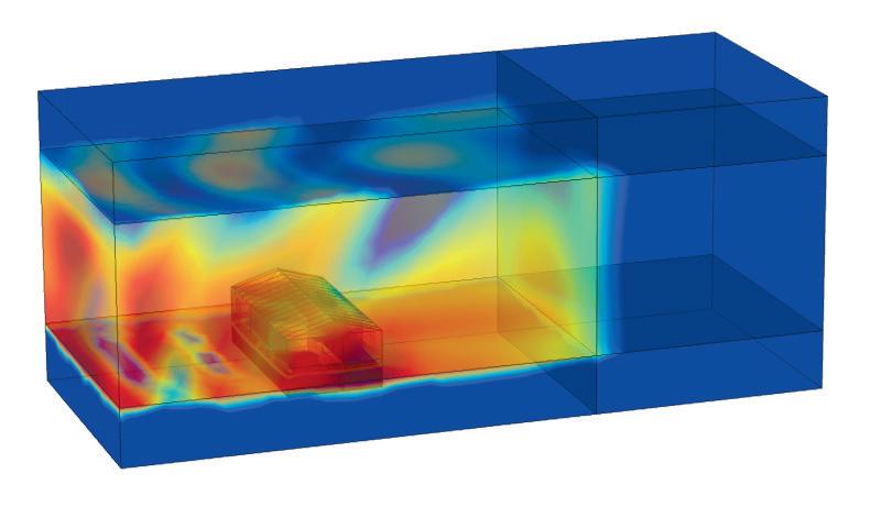
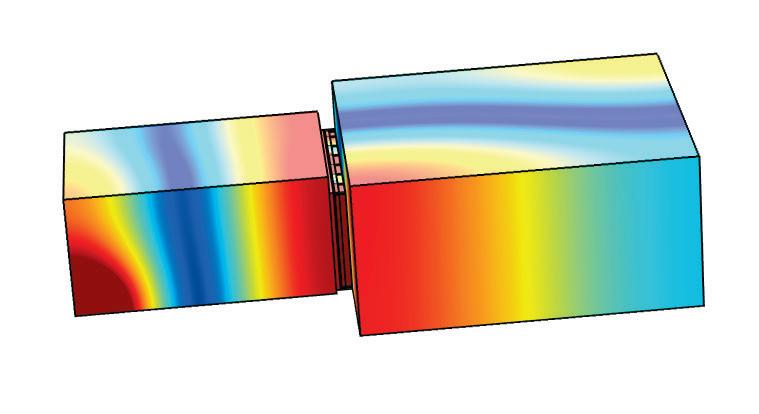
1 Simulated sound pressure in a laboratory with two chambers divided by a wall. A loudspeaker is placed in the room on the left-hand side. The simulations show that the acoustic resonances within each room affect the sound insulation 2 Simulated low-frequency sound originating from outside, around and inside a building. In both cases, the colours indicate the variation in the sound pressure within the rooms and the wall cavities
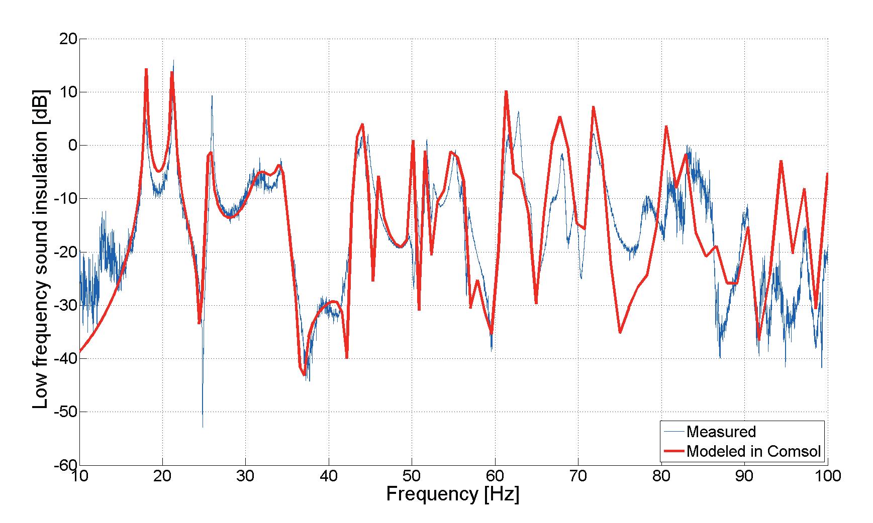
3 The model accurately captures the location of the resonances as well as the level within a few decibels. As the frequency increases, more modes in smaller and smaller structures will get excited. This shows as the increasing difference between the measurements and the model results
3
Løvholt is interested in what happens at the threshold of hearing. He wants to understand how sounds from external sources interact with buildings and generate vibration that is perceived by people. Countermeasures might then be recommended to prevent vibration and standard units might be proposed that recognise the need to account for the ‘annoyance’ factor.
Simulating the spread of sound waves Løvholt and his colleagues decided to create a computer model that would allow them to pick apart the mechanism of lowfrequency sound waves hitting and penetrating a building. They used the Comsol’s Multiphysics software to simulate a wooden structure with two rooms separated by a wall (see figures 1 and 2), closely mimicking the laboratory experiment set-up.
Within the model, they assigned a loudspeaker to one room, a microphone to the other, and placed various probes around the structure in order to monitor sound pressure levels and vibrations. Every component was carefully modelled, including the steel frame, the air cavity and studs in the wall, the windows, the plywood sheet and the plasterboard.
Each element in the model had a resonance that depended on the wavelength of the sound wave and the pressure distribution. For example, there was high pressure in the speaker room and lower pressure in the microphone room, and the resonance of the wall depended on its length, thickness and stiffness.
The team also had to recognise compound resonances – that is, those created when two components are joined, such as two pieces of timber, screwed together. The simulation software allowed them to enter all the parameters to be monitored.
In particular, it enabled them to couple different physics, so they could look at the acoustics of open-air sound interacting with indoor structural dynamics. The coupling works both ways, so feedback can be identified. This coupling was crucial for the analysis, because sound waves can generate a huge range and variety of resonances. The resulting model allows these to be seen.
The NGI team then verified their simulation with laboratory testing of low-frequency sounds as they were transmitted through a wooden construction with two rooms. Løvholt explains that the motion of the wall and the sound pressure level are the main quantities measured and results show very close correlation to the model (see figure 3).
The model shows that the transmission of sound within a building is governed by the way in which low-frequency waves interact with the fundamental modes of the building components, the dimensions of the room and the way in which air leaks from the building envelope. Vibrations in ceilings and walls seem to be the dominant source of low-frequency indoor sound, with floor vibration driven by sound pressure inside the room.
Faster and cheaper testing “We now have a tool to predict sound and vibration at low frequencies,” Løvholt says. “We can use it to design and test mitigation measures such as the lamination of windows and the stiffening of walls – if a wall or window moves less, sound transfers less.”
“In addition, the model shows us the influence small details have on the system; for example, how the screw connection between studs and plasterboards can reduce the effect of a countermeasure, as they actually reduce the overall stiffness of the structure,” he adds.
The next stage for the team will be fullscale field tests on a real house in an area of Norway exposed to aircraft noise. Meanwhile, the team will continue to use and develop the model they created using Comsol Multiphysics.
“We have never achieved this level of agreement with real-life testing before and it is all down to how we were able to model the different structural elements in the multiphysics software,” says Løvholt.
“The model enables us to make decisions and assign countermeasures. This is much cheaper and quicker than physical testing. The model may then be expanded to simulate the sound propagation and vibration in an entire building.”
The future of the built environment
DCW is back and packed with all the latest innovation & technology

Digital Construction Week returns to the Business Design Centre in Islington with a full two-day conference programme, expanded free to attend seminar series, and interactive exhibition.
DCW features sessions on innovation strategies, understanding and creating client value, developing new digital skills and winning work overseas
beginners still finding their way as well as our BIM experts. DCW’s exhibition will house 80+ exhibitors, displaying a wide range of exciting new solutions and technologies including robotics, BIM, AR/ VR, PIM, High Performance Computing, 3D Printing, Cloud Computing and Big Data. This year the exhibition features a blend of major construction firms and consultancies such as Arup, BAM, Bond Bryan and Kier as well as Price Waterhouse Coopers. BAM and Kier will be revealing what technologies they are adopting in the digital age while Arup’s stand will include a special visualisation installation. Other features on the show floor include our exclusive HS2 Pavilion and interactive exhibits. Digital Construction Week will also play host to an evening reception at the Irish Embassy in Westminster which will feature the official launch of the UK BIM Alliance. Several fringe events will take place in central London, more details will be released about these soon.

DCW’s main conference will feature experts from across the industry including Paul Morrell, John Pelton, Anne Kemp, David Philp and Sadie Morgan. Digitising the construction industry involves a lot of transformation and new ways of working. DCW’s conference reflects the dynamism with panel sessions on innovation strategies, understanding and creating client value, developing new digital skills and winning work overseas. The exhibition floor will also feature four dedicated seminar streams – the BIM Village, Digital in Action, Innovation Theatre, and Tech Stage. The Digital in Action seminars will showcase the use of new technology in a series of case studies, including the Severn Tunnel, BAM’s Wharfedale Hospital, the M8 motorway and Rio Tinto’s global mining estate. The Innovation Theatre offers cutting-edge tech set to shape the industry over the next five years; wearables, immersive visualisation, citywide modelling, computational design and smart materials. We have partnered with the UK BIM Alliance for an entirely free BIM seminar programme. Featuring presentations from Anne Kemp and David Philp. Helping industry grow and develop its BIM expertise. With sessions for both BIM Level 2
REGISTER NOW Exclusive AEC Magazine 25% Subscriber Discount. Use Code AECCONF25
www.digitalconstructionweek.com
HEADLINE SPONSORS
Canal concept
In Amsterdam’s Eastern Docklands, a 3D printing project is underway, using bioplastics and concrete to bring to life a Dutch canal house with a difference
DUS Architects is a multidisci- systems (using 3D-printed moulds as nents vary, depending on size and complinary design firm based in casts); and hybrid prints (using a combi- plexity, from around 20 minutes to prothe Netherlands, which is aim- nation of 3D prints and other materials.) duce a tile, to one day for a 5-metre tall ing to use digital fabrication The main load-bearing structure of the element. But the project is not primarily techniques to create affordable, tailor- canal house will be built with concrete, about speed, according to DUS. It’s a made architecture. And what better place produced in unique shapes with the help chance to experiment and, besides, the to put this idea into practice than in the of 3D-printed moulds that can be recy- firm is working on other buildings and firm’s home town of Amsterdam, a city cled, by shredding the material once a products along the way. The 3D Print already known for architectural treas- mould is finished with and reprinting it Canal House is expected to be completed ures: windmills, elaborate drawbridges, as a new mould. at some time in 2018. gabled facades? An added benefit of this ‘smart mould-
In fact, DUS has taken one of ing’ system is that individual building Computing clout Amsterdam’s most iconic designs — that components created in this way can Designing the canal house has required of the traditional canal house — and used incorporate printed areas inside the con- significant computing power, provided it to demonstrate how 3D printing could crete element, which in turn can accom- by Lenovo’s ThinkStation P500 and help the building industry to answer modate cables, wires and pipes. ThinkPad mobile workstations. These some of its most pressing challenges. Infills such as walls, panelling and deliver the storage and memory capacity
These include a shortage of good quali- flooring, meanwhile, will be created that DUS designers need in order to perty housing, as well as the widespread either from full prints or hybrid prints. form extensive rendering in Autodesk standardisation that results in housing Hybrid prints are proving particularly Revit and 3ds Max. stock when building supplies are mass- useful in areas such as urban outdoor The project uses 3D models that typiproduced. Another issue is pollution generated by the industry, not just from the production ‘‘ The main load-bearing structure of the cally range from between 20MB and 150MB per print piece – but model sizes for Autodesk Revit of materials, but also their transportation. The team at DUS believes that canal house will be built with concrete, produced in unique shapes with the projects can weigh in at 500MB and more. Lenovo’s Flex technology for 3D printing can help address all help of 3D-printed moulds interconnectivity and network these issues – and the 3D Print Canal House project is a major test of that conviction. This initiative furniture, where bioplastic allows for a ’’ performance, meanwhile, helps to handle GCode files generated by 3D models as they travel over the netkicked off in 2014 on a temporary build- unique shape and concrete allows for work from workstation to printer. ing site, designed as a growing expo, durability. DUS has used this approach, Network performance is equally critical where the general public could catch an for example, in outdoor benches printed in handling data flowing the other way, early glimpse of the future of building. for its Europe Building, also in from printer to workstation. This
In September 2015, the project moved Amsterdam, which played host to the EU includes printer information, sensor data to a bigger location and became a perma- Presidency during its recent six-month and images. nent building project at Asterweg 49, in stay in the Netherlands. As well as using a number of commerAmsterdam’s Eastern Docklands district. Connecting 3D-printed parts to each cially available 3D printers, DUS also Construction on the 700 square-metre other will rely on traditional methods created its own 3D printer for rapid procanal house is expected to begin in the (concrete, bolts and so on) or newer totyping, named the KamerMaker Spring of 2017. approaches currently under develop- (Dutch for ‘room maker’). This device is ment, including new glues and capable of 3D printing elements with 3D prints, moulds and hybrids 3D-printed connecting mechanisms that dimensions up to 2m x 2m x 5m and uses 3D printing will play a role in the crea- resemble tie-wraps or cable ties. in-house developed software for customtion of all building elements used in the This range of materials should deliv- isation of printed building products. final canal house structure. The material er the flexibility needed to build differ- The building site of the 3D Print Canal used will be a bioplastic developed by ent shapes and structures in the house, House is currently open to visitors by Henkel in collaboration with DUS and which once complete will include office appointment. In addition, DUS will be based on a natural material, linseed. space, workshop areas for 3D printing, hosting several events during 2016 to
DUS, meanwhile, is developing three material recycling facilities, hotel demonstrate the firm’s use of technology types of building product: full prints rooms, cafes and more. on this project. (using 3D-printed material only); concrete Building times for individual compo- ■ 3dprintcanalhouse.com
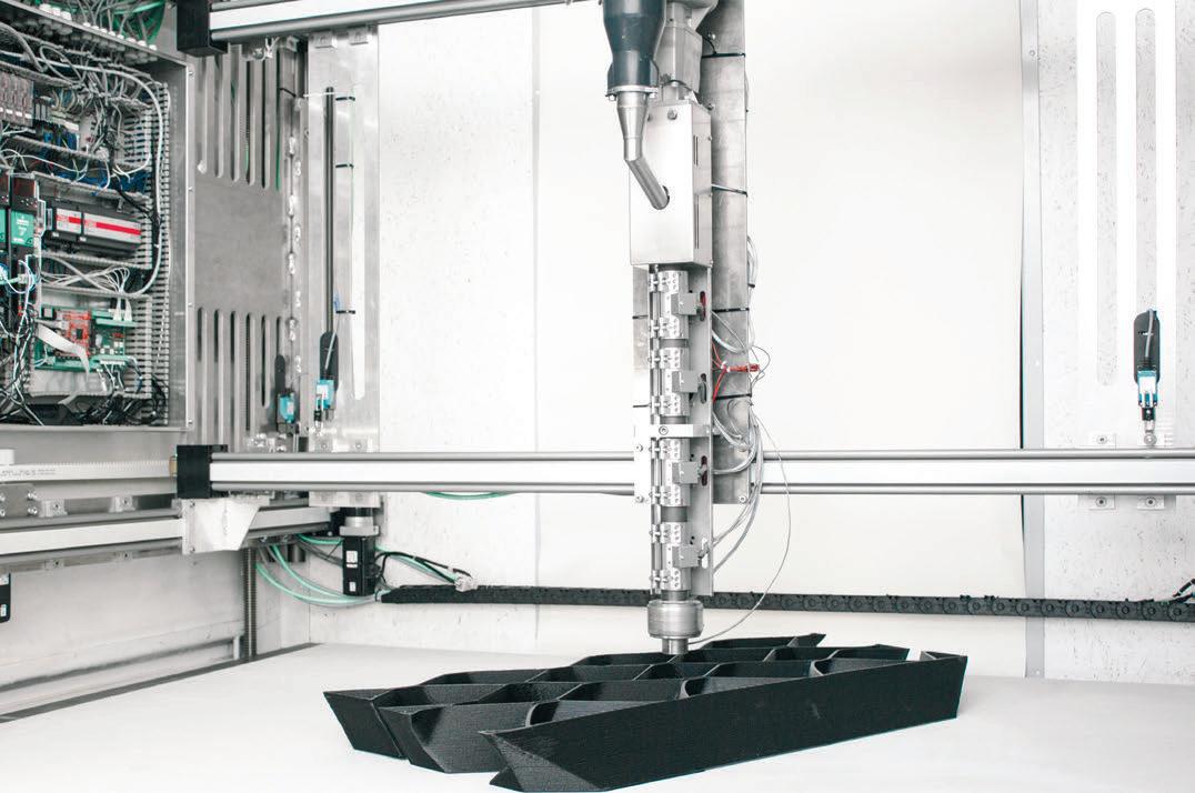
DUS Architects’ KamerMaker (‘Room Maker’) 3D printer in action
A staircase in the 3D Print Canal House, as seen from the side