
XAVIER RODRIGUEZ Architecture Portfolio

Email:Phone:Address: NewEDUCATIONJerseyInstituteof Technology 2020 Summit High School 2009-2013 PROFES SIONAL SKILLS Autodesk GraphicEXPERIENCEPURPOSEConsultantto
& Associates Contact: 973-534-9475 | bob@tsapatsaris.com Michael Sas: Nick Tspatsaris & Associates Contact: 201-820-5741 | michael@tsapatsaris.com
To further my craft and to position myself in an environment that allows me to gain from the knowledge of my peers, and use my own skills to help those around me. I strive to aid my society to rekindle the human interactions we’ve lost, through the designs we conjure. I helped the company by understanding their desires and how they wanted to connect to their clients, and in turn I designed graphics for there business cards and pamphlets
Education
XAVIER RODRIGUEZ Bachelors of Architecture Undergraduate at NJIT 127 1480 US-46 West Parsipanny, NJ, 07054 908-380-6265xrodriguez.arch@gmail.comxir2@njit.edu Bachelors of Architecture Adobe Suite: VRhinocerosAutocadRevitPExcelWInDesignIllustratorPhotoshopordowerpoint-Ray
As a mentor I was able to aid my assigned students with issues they were having as freshmen in my architecture program whether it was for drawings or speaking about there own projects
FDX-AXA Mentor in NJIT Program Contact Number: 908-902-7650 Opportunity Program Tutor The tutors were tasked to aid the incoming freshman in there eld of study. In doing so I was able to teach my students the basics Verrengia: Nick Tspatsaris
to drawing plans, elevations and sections, but also how to analyze a site through diagramsNickREFERENCESTsapatsaris:NickTspatsaris & Associates Contact: 201-281-1111 | nick@tsapatsaris.com REWARDS Design Showcase: 2014, 2017, 2019 Design/ Build Masonry Competition: Best Build 2015 Junior Architect at Nick Tsapatsaris & Associates Worked along side Senior Architects producing permit sets, shop drawings, architectural and structural designs. Directed construction site as superintendent, assisted in surveying sites, and produced proposals as well as change orders. Communicated with subcontracters and clients ensuring satisfaction for all involved CONTENTSOFABLETContact Number: 201-447-7044 Robert


HAVENMOTT TRASHRETHINKING 38-35 GARDEN THRESHOLD 42-39TSAPATSARISNICK ASSOCIATES& 4-3

NICK TSAPATSARIS & ASSOCIATES Junior Architect / Ridgewood, NJ Collaborated with Senior Project Manager, Architect, and Engineer strategizing and executing high quality projects. Projects include all landlord work, as well as corporate, retail, education, residential clients, and tenant improvements. I also worked alongside Senior Architects producing permit sets, shop drawings, architectural and structural designs. I developed a working knowledge of leases directed construction sites as superintendent, assisted in surveying sites, produced proposals and change orders. Laastly, among other things, I communicated with subcontracters and clients ensuring satisfaction for all involved. 03 EXTERIOR PARTITION WITH R-13 BATT INSULATION WITHIN CAVITY 21" GYPSUM, TAPE SPACKLE AND PAINT AS DIRECTED BY OWNER CLR. SIKABIT S-50 SELF ADHERING SHEET WATERPROOFING MEMBRANE, OR APPROVED EQUAL APPROX. GRADE 1'-0" x 2'-0" CONT. CONCRETE FOOTING, PROVIDE 1x4 CONT. KEY 6" PERFORATED FOUNDATION DRAIN W/ FILTER FABRIC, INTERCONNECT WITH EXISTING DRAINAGE SYSTEM. WRAP W/ 43 CLEAN CRUSHED STONE (3) #5 CONTINUOUS #5 @ 12" O.C. HOOK INTO FTG. UNDISTURBED SOIL R-10 RIGID BOARD INSULATION 21" x 18" J-HOOK ANCHOR @ 32" O.C. MAX. 12" FROM CORNERS DOUBLE WOLM. SILL PLATE, PROVIDE TERMITE SHIELD CONTINUOUS AT EXTERIOR WALL 2x FLOOR JOIST, REFER TO STRUCTURE FOR SIZE AND SPACING R-38 BATT INSULATION 85" T&G PLYWOOD SUBFLOOR, GLUED AND HARDIESCREWEDTILEBACKER BOARD, FASTEN AS PER MANUFACTURER SPECIFICATIONS TILE FLOORING AS SELECTED BY OWNER WOLM. RIM BOARD WOLM. " CDX PLYWOOD, EXTEND +/16" ABOVE BRICK LEDGE R-15 RIGID BOARD INSULATION SIKABIT S-50 SELF ADHERING SHEET WATERPROOFING MEMBRANE, OR APPROVED EQUAL 5" CONCRETE SLAB WITH 6 X 6 W2.9 WWM ON 6 MIL VAPOR BARRIER ON 5" CRUSHED STONE 12" REINFORCED CONCRETE FOUNDATION WALL #4 @ 12" O.C. VERTICAL FRONT FACE #4 @ 12" O.C. HORIZONTAL FRONTFACE#4@6" O.C. VERTICAL #4 @ 12" O.C. HORIZONTAL CLR. CLR. #4 @ 6" O.C. VERTICAL BACK FACE #4 @ 12" O.C. HORIZONTAL BACK FACE CLR. #4 NOSING BAR CONT. LAPMINIMUM #4 NOSING BAR CONT. 2% MIN.TYVEKAPPROX.15%HOUSE WRAP, TAPE ALL SEAMS AND WINDOW/ DOOR FRAME, PROVIDE ADDITIONAL FLASHING AT EXISTING WINDOWS & DOORS CEDAR OR HARDIE SIDING TO BE SELECTED BY OWNER 2x6 @ 16" O.C. WOOD FRAMED EXTERIOR PARTITION WITH R-21 BATT INSULATION WITHIN CAVITY 85 CDX PLYWOOD SHEATHING CONTINUOUS VENTED HARDIE SOFFIT, COLOR AS SELECTED BY OWNERCONT.ALUMN. FLASHING AT HARDIE BOARD AND MASONRY INTERSECTIONS R-49 BATT INSULATION AT ATTIC R806.2 MINIMUM VENTED AREA SHALL BE 1/150 OF THE AREA OF THE VENTED SPACE. R806.3 WHERE EAVE OR CORNICE VENTS ARE INSTALLED, BLOCKING, BRIDGING AND INSULATION SHALL NOT BLOCK FREE FLOW OF AIR. NOT LESS THAN A 1-INCH SPACE SHALL BE PROVIDED BETWEEN THE INSULATION AND THE ROOF SHEATHING AND AT THE LOCATION OF THE VENT 43 CDX PLYWOOD SHEATHING 2x RAFTER, REFER TO STRUCTURAL PLANS FOR SPACING AND SIZE 2 LAYERS 15 LB FELT OR APPROVED EQUAL TO MATCH EXISTING HOUSE 30 YR ASPHALT SHINGLE TO MATCH EXISTING HOUSE RIDGE BEAM, REFER TO STRUCTURAL PLANS FOR SIZE 2x NAILER/ BLOCKING AT SOFFIT CLR. #4 @ 12" O.C. VERTICAL #4 @ 12" O.C. HORIZONTAL 8" REINFORCED CONCRETE FOUNDATION WALL 2" x 18" J-HOOK ANCHOR @ 32" O.C. MAX. 12" FROM CORNERS 4" PERFORATED FOUNDATION DRAIN W/ FILTER FABRIC, DISCHARGE PIPE TO GRADE. WRAP W/34" CLEAN CRUSHED STONE (ELEV. 317.33) 4" PERFORATED FOUNDATION DRAIN W/ FILTER FABRIC, DISCHARGE PIPE TO GRADE. WRAP W/34" CLEAN CRUSHED STONE (ELEV. 321.33) BACK FILL WITH FREE DRAINAGE MATERIAL 43" CLEAN CRUSHED STONE SCALE: 1/4" = 1'-0" PROPOSED BUILDING/ WALL SECTIONS
04 L1 L1 E E E EEM P/S A/V EE F3 F3 F3 N.I.C N.I.C N.I.C N.I.C N.I.C N.I.C N.I.C N.I.C N.I.C N.I.C N.I.C N.I.C LIMITS OR AREA COMPLETED AND INSPECTED UNDER INITIAL PERMIT FILING AND WORK NF3 F3N NF3 NEMF4 NEMF4 GYPSUM BOARD SOFFIT, REFER F3NTO DETAIL 8, A-301 ALIGN ALIGN L1 R-1 D-1 L1L1 L1 L1 L1 L1 L1 L1 L1 L1L1L1L1L1L1L1L1L1L1L1 L1L1L1 R-1 R-1 R-1 R-1 D-1 D-1 N N N N NNN NN L1L1L1L1 D-1 NN L1 L1L1L1 L1 L1 L1 L1 L1L1 L1 L1 L1 L1 L1 L1 L1 L1L1L1L1 L1L1L1L1 L1L1L1L1 L1L1L1L1 D-1 D-1 D-1 D-1 D-1 D-1 N L1 L1L1 L1L1N N NN NN NN N N L1L1N L1 L1L1 N N NN L1L1L1 L1 N R-1D-1 L1N L1L1 L1L1 R-1 D-1 N L1L1 L1L1 R-1 D-1 N L1 L1 L1 L1 R-1 D-1 N L1 L1L1L1 R-1 D-1 N L1 L1 L1 L1 R-1 D-1 N L1 L1L1L1 R-1 D-1 N L1 L1L1L1 R-1 D-1 N L1 L1L1L1 L1L1 N L1 N L1L1L1 R-1 D-1 L1 N L1L1L1 R-1 D-1 L1 N L1L1L1 R-1 D-1 L1 R-1 D-1 N L1L1L1L1 R-1 L1L1L1 N D-1 L1 D-1R-1N L1L1L1 L1 D-1R-1N L1L1L1 D-1 D-1 L1L1 L1L1L1 L1 R-1 D-1 D-1 R-1NNN N L1 N N N NNN NN NND-1D-1D-1 L1L1L1L1L1 L1L1 L1L1L1L1 L1 L1 L1L1L1L1 D-1D-1 N N N N D-1D-1 R-1 R-1 R-1 D-1 R-1 D-1 L1 N L1 R-1 D-1 L1L1 L1NN L1L1L1 D-1 R-1 R-1 D-1 D-1D-1D-1D-1D-1 R-1 R-1 R-1 R-1 R-1 R-1 R-1 R-1 R-1D-1R-1R-1 L1 R-1 NEM F4 F3N NF3 N F3 F3N NF3 F3N NF3 NF3 F3N L2 L2 L2 L2 L2 L2 L2 L2 L2L2L2L2L2L2L2L2L2L2L2L2L2L2L2L2L2L2L2L2 L2L2L2L2L2L2 L1L1 SCALE: 1/64" = 1'-0" PROPOSED THIRD FLOOR REFLECTED CEILING PLAN
GROUND PLAN SCALE: 1/64” : 1’-0” SCALE:SECTION:DIAGRAMSAA1/64” : 1’-0” THE SUMMIT Museum / Boonton, NJ The focus of this project was to design a museum in Boonton, New Jersey. My approach for this site was to find a solution to the depleting green spaces the township had been issuing. The museum thus takes the existing topography and mirrors it onto the roof, thereby allowing for the possibility to place a green roof where the local artist of the township may place there sculptural pieces. The museum itself would be placed within a space wrapped by a glass facade, to draw less attention to the building and more so to the mirrored topography. The museum itself is an outlet for those of the Boonton to inhabit and take advantage of the newly designed green space. CC CC AA AA BB BB 05
SECOND PLAN SCALE: 1/64” : 1’-0” ROOF SCALE:PLAN1/64” : 1’-0” SECTION: BB SCALE: 1/64” : 1’-0” SECTION: CC SCALE: 1/64” : 1’-0” 06
07


08


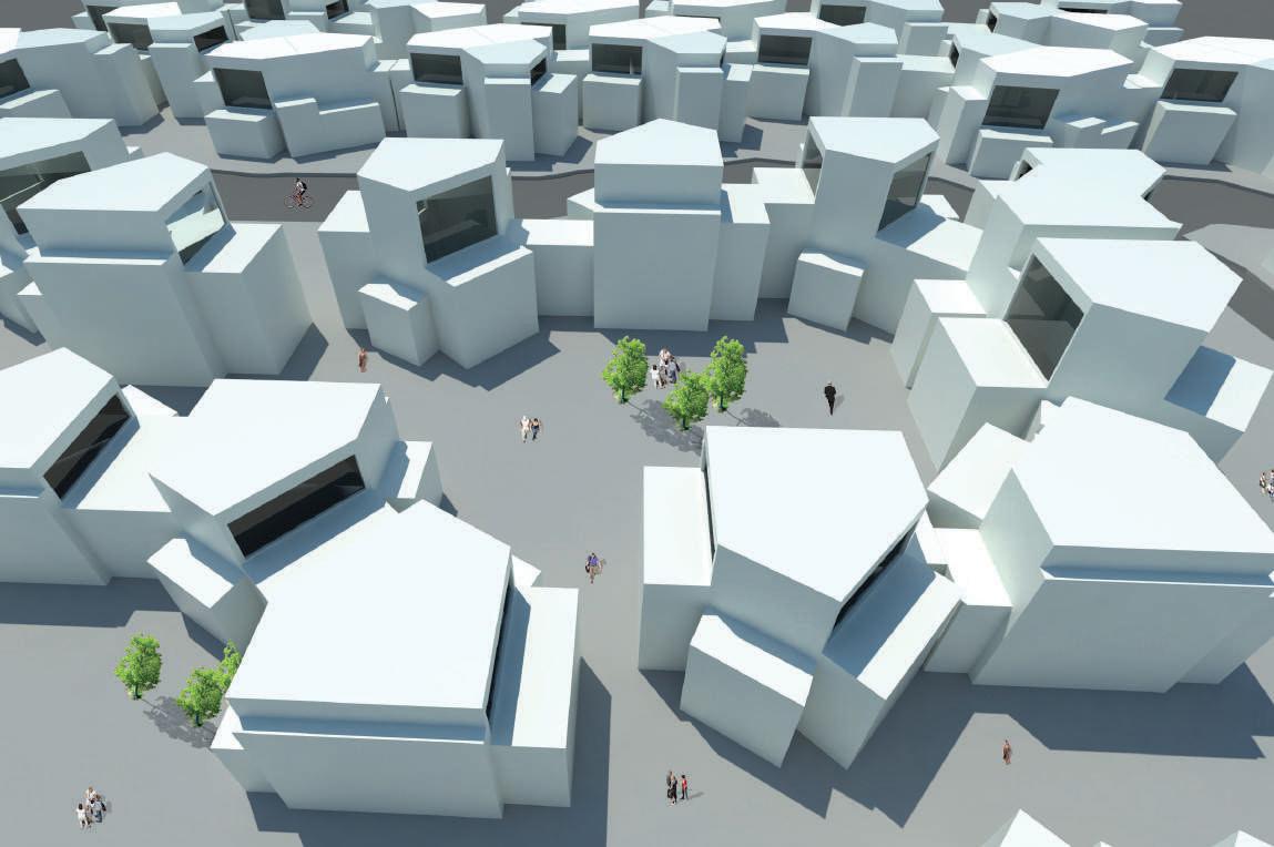
GROUND PLAN SCALE: 1/32” : 1’-0” AGGREGATION SCHEME 09
MICRO LIVING Micro Unit Community / No Location For this project my focus was to design a micro unit and in turn design a community space for the residents. I approached this by rst designing a micro unit and my goal for the unit was to have di erent aggregations of living. It was designed for the main living components and placing di erent privacy levels to these spaces by altering the height of the rooms ceilings. From there I began to design the city in the same method i designed the units. And so I had taken the six units of design and I began to arrange them in di erent aggregation schemes ranging from the amounts of units in use. And so during this process I began to see a relationship in privacy amongst the aggregations, which I decided to take advantage. The advantage was to design a community which had three sectors with a di erence in privacy levels based on the space in between units. This scheme also allowed for an implementation of courtyard spaces which were di erent for each sector Cluster Interlocking
Facade Alignment
TOWN SCALE:PLAN1/64” : 1’-0” AAAA BBBB 10
SCALE:SECTION:AA1/32” : 1’-0” 11


SECTION: BB SCALE: 1/32” : 1’-0” 12

PAS SAGE OF INTERACTION Police Station / Perth Amboy, New Jersey
The City of Perth Amboy has commissioned a police station to be constructed by the local train station to improve the walkable downtown area and to provide a secure and welcoming access point from the train terminal to the most active street, Smith Street to the north. At the site, the heaviest tra c occurs at the Perth Amboy Train Station and Smith Street. Commuters returning from work use the train while local pedestrians walk along Smith Street towards the commercial district in Perth Amboy. The concept of this design is to provide a route for commuters arriving from the Perth Amboy Train Station onto Smith Street. At the same time, the route is also open up to the local pedestrians walking along Smith Street and features a community center for various activities. A vertical connection, through the use of a grand stairway in the embankment, pr ovides a direct route from the train platform to Smith Street for commuters. This stairway can also serve as a public seating among the steps and a wide circulation space. In consideration for the local community, a route is provided through the site and leads up another staircase towards the community center. Elevated and separated from the primary circulation space, a public green space is generated directly above the police station, where the community can walk and socialize. The barrel vault over the grand stairway is inspired by the arches in the train station. To showcase the ability of brick and to emphasize the horizontally of the facade on Elm Street, we implemented arches. Screens were added on the North and South elevations to provide sunlight while still providing privacy. Re ection pools were added in front of the screens to enhance the vertically of the brick columns on the facade and to deter the public from looking directly into the screen.
GROUND PLAN SCALE: 1/32” : 1’-0” AA PROGRES SION DIAGRAM AABBBB SECTION AA SCALE: 1/32” : 1’-0” 13
SECOND LEVEL PLAN SCALE: 1/32” : 1’-0” BASEMENT PLAN SCALE: 1/32” : 1’-0” AA AA BB BB AA AA BB BB SECTION BB SCALE: 1/32” : 1’-0” 14
15


16


KIOSK BRICK BUILD Kiosk / Newark New, Jersey / Studio Project Within this project we took my previous project “Passages of Interaction” and focused on its main ideas. We approached the 6’ x 8’ x 8’ site by replicating the main passages and carving it out of the site. We then decided to place stands for a place mat and seating along various areas of our site, further carving away from it. We then placed arches amongst the remaining walls, resembling my previous project. Lastly we placed a roof over the interior spaces for shelter and to have on top a green roof. This projects goal was to act as a place of gathering and interaction while appreciating the tectonic value. PROGRESSION DIAGRAM 17


18


THRESHOLDS Community Clinic / Newark, New Jersey
CLINIC COURTYARD PROGRESSION DIAGRAM SECTION AA SCALE: 3/64” : 1’-0” AXONOMETRICEXPLODED 19
The focus was to design a clinic that was able to become a community center for the city of Newark. I first approached the project by understanding how nature might impact health by doing so i was able to understand the importance of light and plant life to ones health. Thus I took the site and wrapped it within a screen barrier with perforations sizes based on the privacy levels of the program. I then decided my program was to be clinic and a courtyard. But I wanted the two to be there own entities, which is why i decided to divide the two with a wall which contained narrow passages creating a sense of path to both programs. I then saw an opportunity for the community to gain a much needed green area thus i made the east portion of the project into a small field of trees to inhabit and the second l evel have a community garden. I then decided to design my roof scheme based on the program below, thus i implemented sky lights whose dimensions were scaled based on the privacy levels of each area.
GROUND PLAN SCALE: 1/64” : 1’-0” AA SECOND LEVEL PLAN SCALE: 1/64” : 1’-0” SECTION BB SCALE: 3/64” : 1’-0” BB AA BB AA BB AA BB 20
21

22


PATHS OF CULTURE Cultural Hub / Jersey City, New Jersey As I designed the cultural hub in Jersey City I looked at a site context and what the area needed. My goal for the site was to create a social gathering hub for the community, thus I took the main areas of circulation flow and connected them by splitting my mass in two. This path is meant to be an area where both parties may merge and enjoy the space provided. Then I looked at what the site had already been provided, and I had noticed a farmers market on the site and the college was one of New Jerseys leading culinary schools, thus I decided to make the first level a space for both farmers market and the culinary school. I then placed the rest of the program while having each of them step back creating a cascade affect, further explored with fin panels exploring the idea of sun analysis on the site to decrease heat upon the building. Commuter College GROUND PLAN SCALE: 1/64” : 1’-0” PROGRESSION DIAGRAM SECTION AA SCALE: 1/64” : 1’-0” AA SECOND LEVEL PLAN SCALE: 1/64” : 1’-0” AA BB BB AA AA BB BB 23

25


26


29

30

THE EXTENSION Signature Building / Newark, New Jersey “Signature Building” has been a term used to define a site and what it represents, but how does one do this? My belief one this question is not set in stone, yet defined by how the the building interacts with the language given by the site and answers the needs. NJIT lacks communication within the campus leading to a strong disconnection between the colleges. Thus the task in hand was to design a space for all to enjoy one anothers company. So to accomplish this task I began with three major spaces: Courtyard Space, University Space, and Green Terrace; providing spaces for all students to come together. I introduce Studio Spaces within the 3rd and 4th floor in which arises another task. What is to become of architecture school in the future? Through my research of schools teaching methods there is a shift to create community learning, taking down the walls surpressing students thoughts. Allowing for an opportunity to create an open space, dividing the space into lounge and work, relieving the stresses that come with architecture. ROBOTICS LAB 6,250 sq. ft. MECHANICAL SPACE 3,325 sq. ft. BATHROOMS 240 sq. ft. STORAGE 350 sq. ft. LECTURE HALLS : 3,525 sq. ft. PRESENTATION ROOM 675 sq. ft. EXHIBITION GALLERY 4,000 sq. ft. BATHROOMS 240 sq. ft. STORAGE 200 sq. ft. LOUNGE SPACE 5,300 sq. ft. KITCHEN : 975 sq. ft. COMPUTER LOUNGE 3,350 sq. ft. BATHROOMS 240 sq. ft. CREATIVITY COMMONS 2,250 sq. ft. STUDY ROOMS 400 sq. ft. GREEN ROOF : 2,650 sq. ft. GREEN TERRACE 7,700 sq. ft. STUDIO SPACE 9,650 sq. ft. MODEL MAKING SPACE 400 sq. ft. REVIEW SPACES: 1,550 sq. ft. LOUNGE SPACE 1,200 sq. ft. BATHROOMS 240 sq. ft. STORAGE 150 sq. ft. OFFICE SPACES 400 sq. ft. THIRD PROGRAMSECONDPROGRAMFLOORDIAGRAMFLOORDIAGRAM STUDIO SPACE 6,200 sq. ft. MODEL MAKING SPACE 400 sq. ft. REVIEW SPACE 1,550 sq. ft. LOUNGE SPACE 875 sq. ft. BATHROOMS 240 sq. ft. OFFICE SPACE 400 sq. ft. FOURTH PROGRAMBASEMENTPROGRAMGROUNDPROGRAMFLOORDIAGRAMFLOORDIAGRAMFLOORDIAGRAM LOBBY 625 sq. ft. COURTYARD 9,350 sq. ft. LOBBY 2,000 sq. ft. SUMMIT STREET DR. MARTIN LUTHER KING JR. BLVD STREETWARREN SITE SCALE:PLAN1/512“ COURTYARDBUILDINGGREEN TERRACE DIVIDING GROUND INTO 3 SPACESCREATING FOOTPRINT BY ENTRY GRIDLINES Fourth Floor Plan: Scale: 3/128” Third Floor Plan: Scale: 1/32” Aspect Drawing: Connection to Site and Colton / Weston South Elevation Scale: 1/128” North Elevation Scale: 1/128” West Scale:Elevation1/128” East Scale:Elevation1/128” AAAA CCCC BBBB AAAA CCCC BBBB 31

GREEN ROOF ELEVATING PUBLIC SPACE CONNECTING ALL PUBLIC SPACESSHIFTING SPACE ALLOWING ADDITIONAL SUNLIGHTSKY BRIDGES CONNECTING BOTH COLLEGES Second Floor Plan: El: 122’ Scale: 1/32” Ground Floor Plan: El: 105’ Scale: 1/32” Basement Floor Plan: El: 93’11” Scale: 1/32” Section AA Scale: 3/64” Section BB Scale: 3/64” AA AA CC CC BBBB AA AA CC CC BBBB AA AA CC CC BBBB 32
WIRES WALL SCALE:SECTION1/8” SECTION CC PERSPECTIVE 33
34


GROUNDPLANFLOOR PLAN
CREATING NEW EXTENSION BETWEEN HIGH WAY AND SITEEXTENDING STREET GRID PROCCESS DIAGRAMS
BETWEEN GROUND AND ROOF
PLACING PROGRAM ONTO SITEWASTE SHEET
N
PROGRAM
MOTT HAVEN RETHINKING WASTE Park and Waste Facility / Mott Haven, New York Long Haul Garbage Trucks w/o Garbage Cap Long Haul Garbage Trucks w/ Garbage Cap AMOUNT OF GARBAGE TRUCKS WITHIN NYC SOUTH BRONX 1144 501 442BROOKLYN193 220 96 206 90 QUEENSREST OF NYC There are over 1,000 more Garbage Trucks that pass through South Bronx in comparison to any other part New York City 97583 102441 176420 96874 99026 4979 25035 43465 43465 8476 2904 3343 DAILY TRAFFIC DIAGRAM The main truck routes for Mott Haven can directly mirror onto the amount of daily traffic seen within the site TRUCKSITE ROUTE 1 TRUCK ROUTE 2 TRUCK ROUTE 3 TRUCK ROUTE 4 TRUCK ROUTE 5 TRUCK ROUTE 6 BARGE ROUTE RAIL ROUTE WASTE ROUTES TO SITE Garbage broken down into residential, commercial, construction and demolition which 75% of waste collected by private companies 35
CONNECTING ROOF THROUGH ARIAL PLATFORMSORGANIC CONNECTION
CREATING
Mott Haven has become the Mecca to a majority of NYC Waste, giving them areas cluttered with waste and pushing away life. In addition the waterfront has become a space purely for industries, rather then sharing the land with the residents of Mott Haven. Another issue is that the Major Deegan Express Way has created a major issue within Mott Haven, being the primary route for garbage trucks, which has lead to air pollution and health hazards. Garbage is broken down into residential, commercial, construction and demolition which 75% of waste is collected by private companies. The main truck routes for Mott Haven can directly mirror onto the amount of daily traffic seen within the site. There are over 1,000 more Garbage Trucks that pass through South Bronx in comparison to any other part of New York City. With this research the goal of the project is to reduce truck movement, change perception, and reinvigorate the waterfront. Thus designing a main facility for waste rather then the multiple waste stations within Mott Haven, and hiding this main facility with a grand park for residents to truly enjoy a luscious green space and the waterfront. N ROOF


37 TRANSECT
38


40

41

42

THANK YOU

