
MODEL
134-172 4-CYLINDER
GASOLINE AND DIESEL ENGINES
SECTION :3 - FORD ENGINE SERVICE MANUAL
40540160
IReprinted I
CONTENTS ENGINE SYSTEMSCYLINDER HEAD AND VALVES .••.. •...•........................... 3 OIL PAN, OIL PUMP AND OIL FILTER ...•................•.••......•.•.•. • • .•.•.•• 11 CONNECTING ROD, BEARINGS, PISTONS, RING AND CYLINDER BLOCK ......• • • • • 16 MAIN BEARINGS, BALANCER, FLYWHEEL AND CRANKSHAFT .....•... ••• • •.. 23 ENGINE GOVERNOR AND TIMING GEAR COVER • • • • • • • 30 CAMSHAFT AND CAMSHAFT GEAR ....• • • 32 ENGINE TUNE·UP ......•.......•..••.•.•..... ...•...........•...•.••......•• 34 TROUBLE SHOOTING ..........••.•.............................•..••..•.....•. , 37 SPECIFICATIONS ••..••••••.......•........... ....•... .•.••..• • 43 SPECIAL TOOLS • • • • • • • • • • • • • • • • • 48 ELECTRICAL SYSTEMBATTERY ..•. ..•• .•• •......•....•........ ........•........•...•.......... 51 GENERATOR AND CHARGING CIRCUIT ...............••...•.•..• • • • • • • 52 STARTING MOTOR, SOLENOID AND STARTING CIRCUIT • • 60 LAMPS AND LIGHTING CIRCUIT • • • • • • 64 MANIFOLD HEATERS, RELAY AND ELECTRICAL CIRCUIT - DIESEL ....•• , ..••••..•........ 66 TROUBLE SHOOTING • • • • • • • • • • • • • • 67 SPECIFICATIONS .•...... •••..••••......••.•. •.•••••..••.•... 73 SPECIAL TOOLS •.•••• , ..•.••••.••.•.•...•.............•.•..••.••..•.•....... 73 IGNITION SYSTEMIGNITION SWITCH .........••.••.•.•.••••••.•..••.....•......... ,............... 74 SPARK PLUGS AND IGNITION WIRES .•..•.............•••.•..••................• • 75 COIL •... , ••••.......... .• ••••..•........................•....••••••.•....... 75 DISTRIBUTOR ..•.•.••• • •••.••••...•.•..............•.•....•....••.•........... 76 TROUBLE SHOOTING •............•..••.•.•.................. .. ........••• , .... , 83 SPECIFICATIONS ..........•• , ..•.•.•••••.•••. .•.• .•••••..•. 86 SPECiAL TOOLS ..••..•••••••....• , •.• < 81 FUEL AND EXHAUST SYSTEM - GASOLINE AIR CLEANER ......•.•. , •.. , •••••.....•.....•.. , .....••.•••.•.•.••...•......•• 88 CARBURETOR • .••••.•••• • .•..... •.. .•.......... •. , 90 FUEL TANK, SEDiMENT BOWL AND LINES •..... .. .••..••..••. . ...............••.. ,... 94 MANIFOLD, MUFfLER AND EXHAUST PIPE , , ••••••••......•....•......... , , , ...•. 95 TROUBLE SHOOTING , •.... •• ••••.. .......•.............. 98 SPECIFICATIONS ............• , .•••••.............•....•.... , , •.....•.. " ••• 99 SPECIAL TOOLS .........••••••••••.••.•........... , . . • . . . . . . . • • . . . . • • • • . • . . . .. 99 FUEL AND EXHAUST SYSTEM - 01 ESEL AIR CLEANER ...... , ..........•.•..•••••.... , .. .. , ......................... ,. 100 FUEL TANK •............•.••••••.••.••.••........• , •.•..••. , .....•.......... 101 IDLE AND HIGH SPEED ADJUSTMENTS .•.•..............••..••................•.• ,. 102 FUEL FILTER .. ..........•.. . .......... . .•• ....... .•..•.•....... . . , .•..•••••. 103 FUEL INJECTORS .• , ..•.•• ........• ••.•..•.•••••••. .• ... .... .................. 104 FUEL INJECTION PUMP ..•..•........•....................... ,.. 109 MANIFOLD, MUFFLER AND OUTLET PIPE •••..•••...... .•... , ..•••...........• ,. 111 TROUBLE SHOOTING •.. ..... ..•.•• , •.••... .. ••. .• , ••••••..•.• . ....... , . . . . . . .. 113 SPECIFICATIONS .....•.•..•......•....•.•••• . •. .. .....•• , . .. .. . ............... 115 SPECIAL TOOLS • .•••. •••••.•. ...•. ••••••.......• .• , 115 COOLING SYSTEMCARE OF THE COOLING SYSTEM .....••••••.••• ... .. ..... ........•........... ... •. 116 RADIATOR, HOSE AND PRESSURE CAP , .. . .•.• , ••••.•...•.. .. ......••.•.•...... ... . 117 WATER PUMP •.....•.•........•••.•.............•...••.••.... , .......•• 119 THERMOSTAT .• .......•. ......•••••••..•• ,................. 120 FAN AND GENERATOR BELT ••••.•.••.. •... •.. ' " 121 TROUBLE SHOOTING .....•. • ..•.............••.••••• , • 121 SPECIFICATIONS .•••.•.• ..•..... .••••••.•••.. ........•.• .• 123 SPECIAL TOOLS ..••.••... , ...•....•........•••..••.................. " 123 2
CYLINDER HEAD AND VALVES
The cylinder head assembly consists of the rocker arm mechanism, valves, springs, and valve guides.
The procedures below cover the removal, disassem· bly, cleaning, inspection, repair and assembly of the cylinder head and valves.
A. Cylinder Head Removal
1. Remove the hood. Drain the coolant from the radiator and cylinder block.
2. Remove the fuel tank and fuel tank support brackets.
3. Disconnect the muffler from the exhaust manifold.
Gasoline Engine: Disconnect the choke rod and accelerator rod from the carburetor.
Gasoline or L P-Gas Engine: Disconnect the fuel line from the fuel filter or carburetor. Disconnect the spark plug wires at the plugs.
CAUTION: ReJer 10 Chapter n, Section 6 beJore attempting the removal oj an LP·Gas Juel tank.
Diesel Engine: Remove the air deaner tube. Disconnect the manifold heater wires at the manifold heaters.
4. Remove the nuts and washers that attach the intake and exhaust manifold to the cylinder block. Remove the manifold.
NOTE: On diesel engines, the intake maniJold is separate from the exhaust manifold.
5. Disconnect the water temperature gauge from the cylinder head. Remove the radiator upper hose.
6. Disconnect the adjusting link from the power steering pump. Remove the bolts that attach the pump to the cylinder head and the water outlet elbow.
7. Remove the rocker arm cover and gasket.
8. Loosen the rocker arm support attaching bolts evenly and alternately until all tension has been relieved then :remove the bolts and washers.
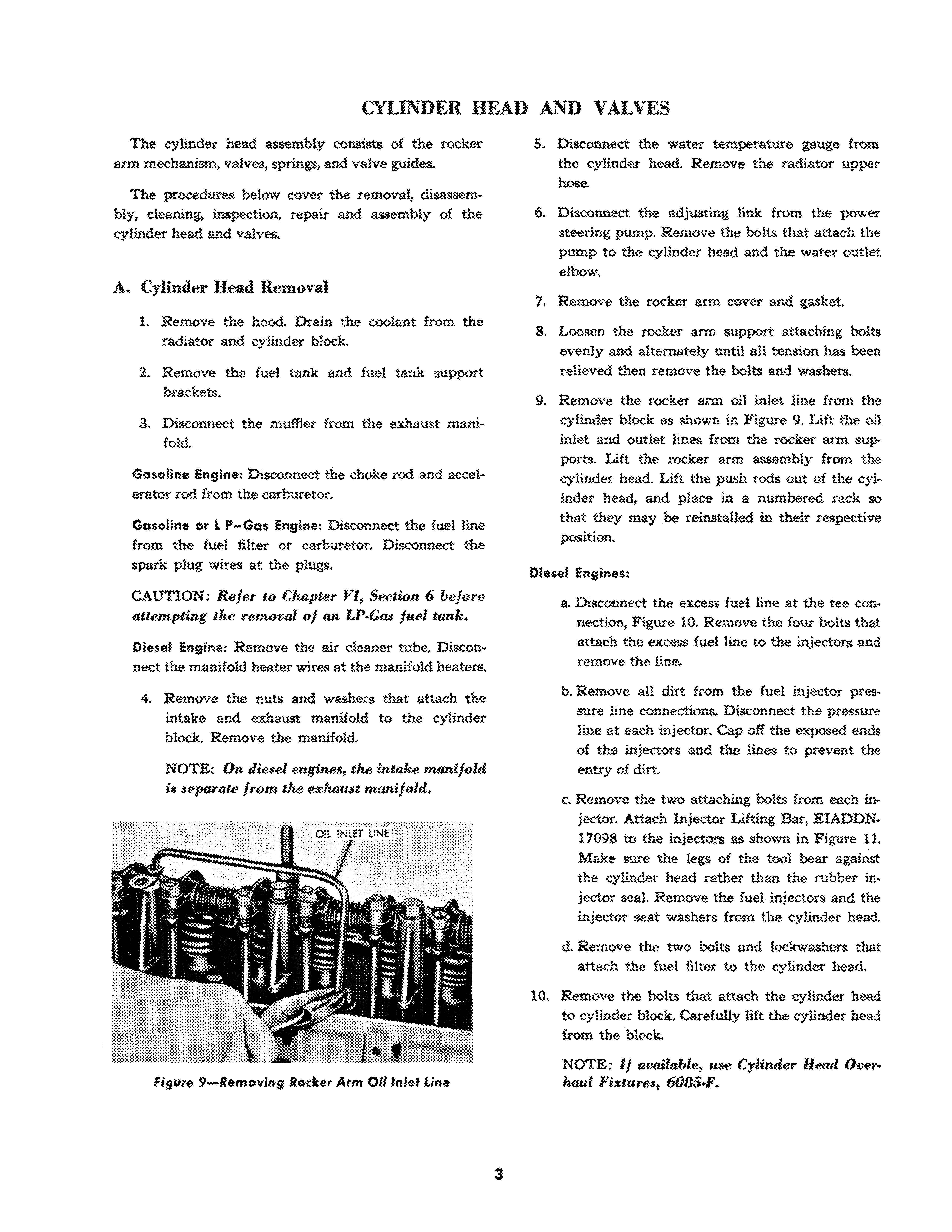
9. Remove the rocker arm oil inlet line from the cylinder block as shown in Figure 9. Lift the oil inlet and outlet lines from the rocker arm sup-ports. Lift the rocker arm assembly from the cylinder head. Lift the push rods out of the cylinder head, and place in a numbered rack so that they may be reinstalled. in their respective position.
Diesel Engines:
a. Disconnect the excess fuel line at the tee connection, Figure 10. Remove the four bolts that attach the excess fuel line to the injectors and remove the line.
b. Remove all dirt from the fuel injector pressure line connections. Disconnect the pressure line at each injector. Cap off the exposed ends of the injectors and the lines to prevent the entry of dirt.
c. Remove the two attaching bolts from each injector. Attach Injector Lifting Bar, EIADDN. 17098 to the injectors as shown in Figure 11. Make sure the legs of the tool bear against the cylinder head rather than the rubber injector seal. Remove the fuel injectors and the injector seat washers f:rom the cylinder head.
d. Remove the two bolts and Iockwashers that attach the fuel filter to the cylinder head.
10. Remove the bolts that attach the cylinder head to cylinder block. Ca:refully lift the cylinder head from the 'block.
NOTE: If available, use Cylinder Head Over.
haul Fixtures, 6085-P.
3
Figure 9-Removing Rocker Arm Oil Inlet Line
B. Cylinder Head Disassembly
1. Remove the two bolts and lockwashers that attach the water outlet elbow to the cylinder head. Remove the elbow and thermostat.
2. Prior to removing the valves, dean all carbon deposits from the combustion chambers. Position Valve Spring Compressor 6513-E& over the valve and spring as shown in Figure 12 and compress the valve spring. Remove the two va lve spring retainer locks, sleeve, retainer, spring and

spacer from each valve. Lift the valves from the head and place them in a numbered rack so that they can be installed in their respective guides.
NOTE: Exhaust valves are provided with a cap and do not have a sleeve. Spacers are used originally only under the exhaust valve springs on diesel engines.
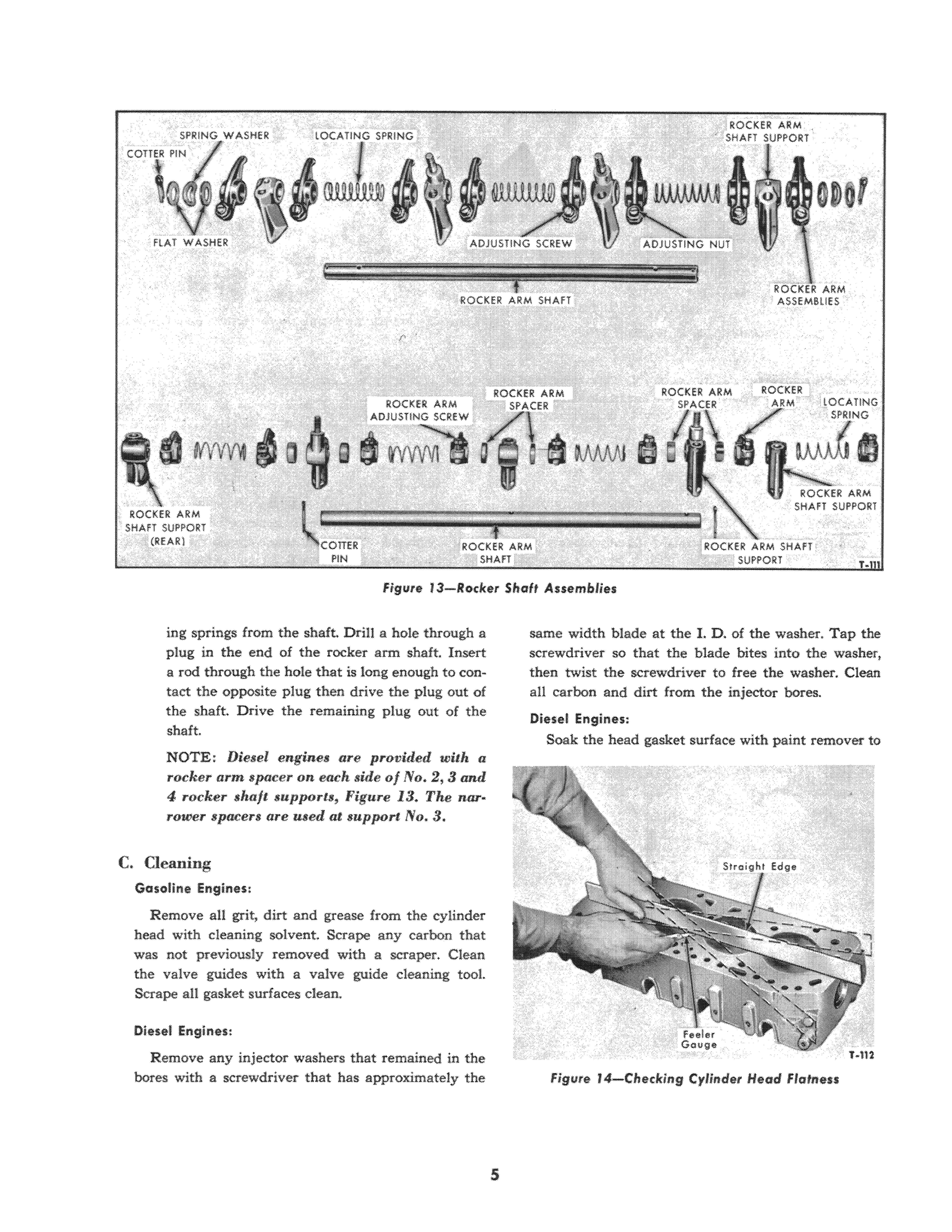
3. Remove the cotter pin, flat washers and spring washer from each end of the rocker shaft, Figure 13.
NOTE: Diesel engines do not have the fW.t washers and spring washer.
Remove the rocker arms and rocker arm locat-
Figure 10- Diesel Engine With Rocker Arm Cover Removed4
Figure J i-Removing Friel Iniedon
figure 12-llemoving Volve Spring Retainer Locks
ing springs from the shaft. Drill a hole through a plug in the end of the rocker arm shaft. Insert a rod through the hole that is long enough to contact the opposite plug then drive the plug out of the shaft. Drive the remaining plug out of the shaft
NOTE: Diesel engines are provided with a rocker arm spacer on each side of No.2, 3 and 4, rocker shaft supports, Figure 13. The narrower spacers are used at support No.3.
C. Cleaning
Gasoline Engines :
Remove all grit, dirt and grease from the cylinder head w ith cleaning solvent. Scrape any carbon tha t was not previously removed with a scraper. Clean the valve guides with a valve guide cleaning tool. Scrape an gasket surfaces dean.
Diesel Engines:
Remove any injector washers that remained in the bores with a screwdriver that has approxim a tely the 5
same width blade at the I. D. of the washer. Tap the screwdriver so that the blade bites into the washer, then twist the screwdriver to free the washer. Clean all carbon and dirt from the injector bores.
Diesel Engines:
Soak the head gasket surface with paint remover to
Figure 13-Rocbr Shaft Assemblies FiglJre 14-Checking Cylinder Head Flatnessloosen the gasket materiaL Carefully scrape the gasket from the head, applying the paint remover as required.
CAUTION: Do not allow paint remover to contact the body or clothing.
Clean aU carbon and dirt from the valves with a mechanical wire brush. Clean all sludge and dirt from inside the rocker shaft. Discard all old gaskets and seals.
D Inspection
L Inspect the cylinder head for being cracked, nicked or burred on the gasket surfaces. Replace the head if it is cracked. Remove all burrs or nicks with an oil stone. With a straight edge and thickness gauge, check the flatness of the cylinder head as shown in Figure 14. Specifications for flatness are 0 005 inch maximum overall or 0.003 inch in any 5 inches. Check the exhaust
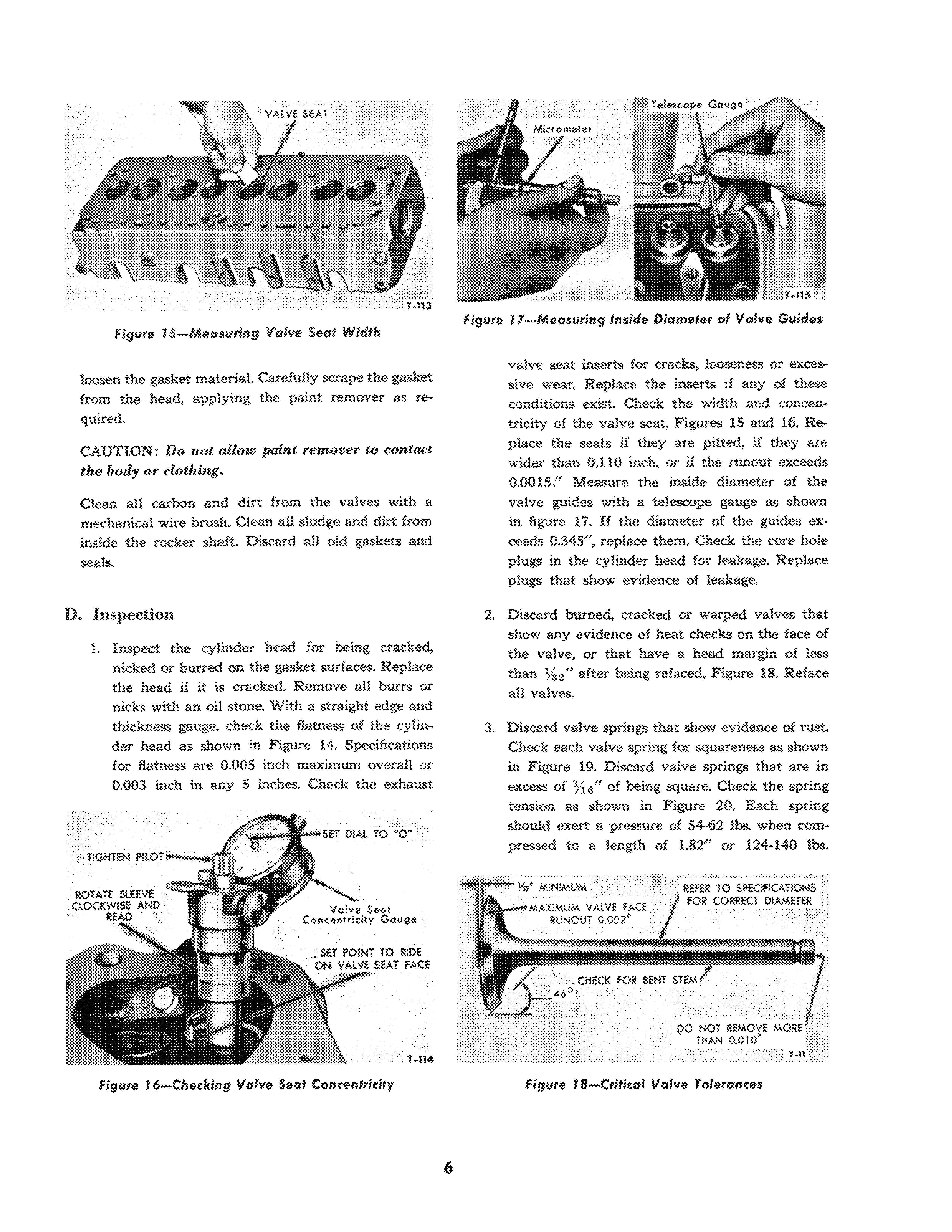
valve seat inserts for cracks, looseness or excessive wear. Replace the inserts if any of these conditions exist. Check the width and concentricity of the valve seat, Figures 15 and 16. Replace the seats if they are pitted, if they are wider than 0.110 inch, or if the runout exceeds 0 0015." Measure the inside diameter of the valve guides with a telescope gauge as shown in figure 17. If the diameter of the guides exceeds 0.345", replace them. Check the core hole plugs in the cYlinder head for leakage. Replace plugs that show evidence of leakage
2. Discard burned, cracked or warped valves that show any evidence of heat checks on the face of the valve, or that have a head margin of less than 7h" after being refaced, Figure 18. Reface an valves
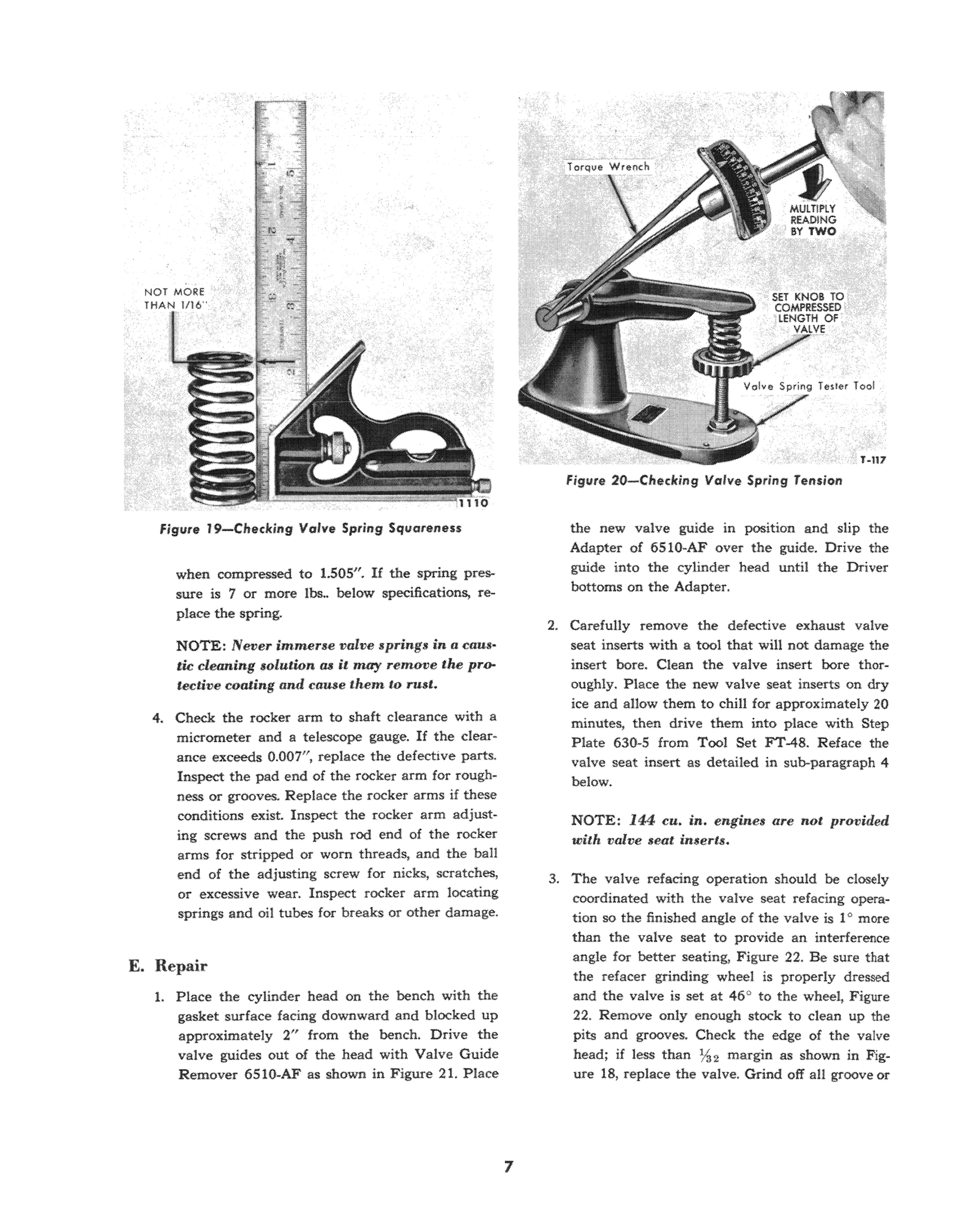
3. Discard valve springs that show evidence of rust. Check ea.ch valve spring for squareness as shown in Figure 19. Discard valve springs that are in excess of nu/l of being square. Check the spring tension as shown in Figure 20. Each spring should exert a pressure of 54-62 100. when compressed to a length of 1.82" or 124-140 100.
Figure J 5 - MeQ'surin9 Valve Seal Width6
Figure 16-Checkin9 Valve Seat Conc e ntricity
Figure 17-Measllring inside Diamefer of Valve Guides
Figllre f'-Critical Valve Tolerances
when compressed to 1.505". If the spring pressure is 7 or more 100.. below specifications, re-place the spring.
NOTE: Never immerse valve springs in a tic cleaning solution as it may remove the protective coating and cause them to rust.
4. Check the rocker arm to shaft clearance with a micrometer and a telescope gauge. If the clearance exceeds 0 007", replace the defective parts. Inspect the pad end of the rocker arm for ness or grooves. Replace the rocker arms if these conditions exist. Inspect the (ocker arm adjusting screws and the push rod end of the rocker arms for stripped or worn threads, and the ball end of the adjusting screw for nicks, scratches, or excessive wear. Inspect rocker arm locating springs and oil tubes for breaks or other damage.
E. Repair
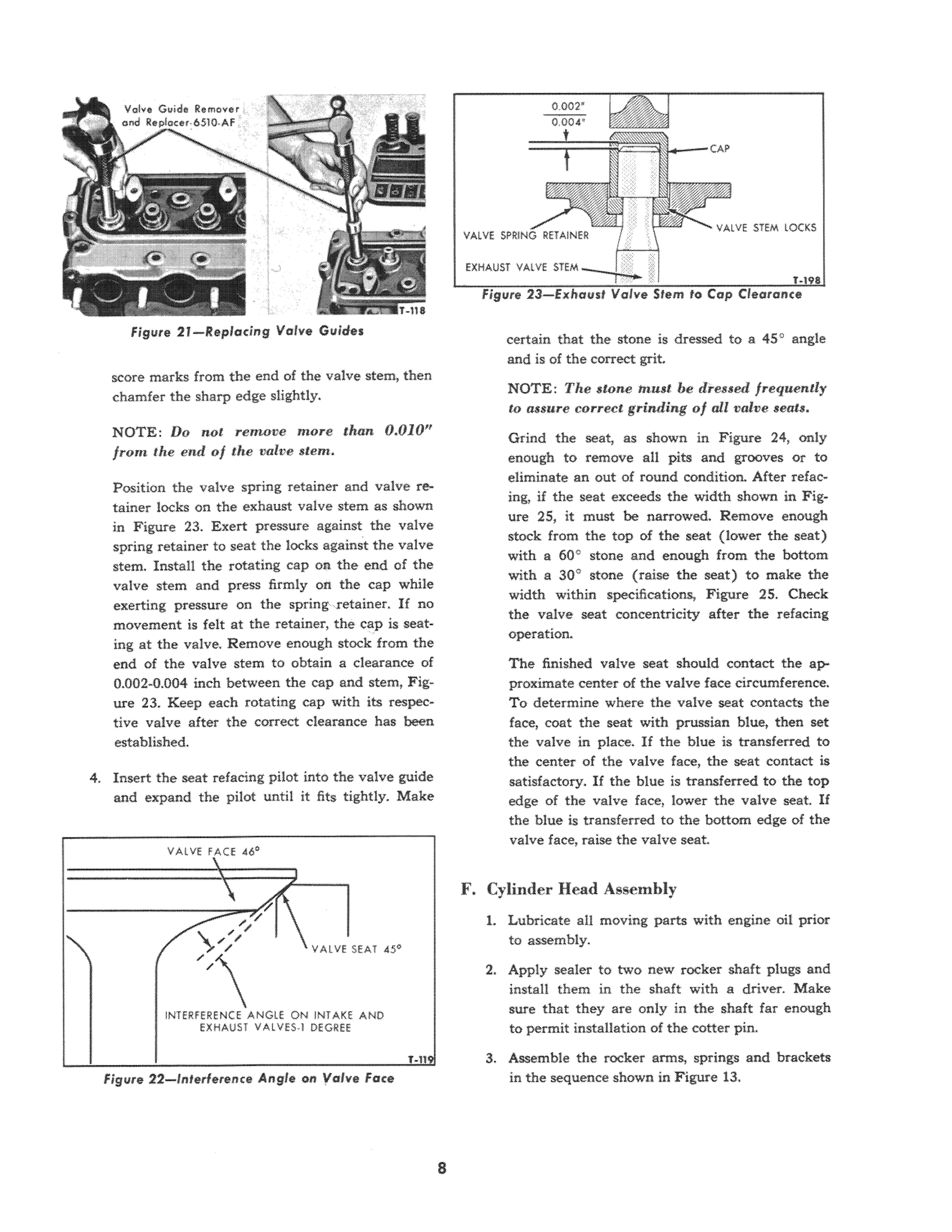
1. Place the cylinder head on the bench with the gasket surface facing downward and blocked up approximately 2" from the bench. Drive the valve guides out of the head with Valve Guide Remover 6510-AF as shown in Figure 21. Place 7
the new valve guide in position and slip the Adapter of 6S10-AF over the guide. Drive the guide into the cylinder head until the Driver bottoms on the Adapter.
2. Carefully remove the defective exhaust valve seat inserts with a tool that will not damage the insert bore. Clean the valve insert bore thoroughly. Place the new valve seat inserts on dry ice and aHow them to chill for approximately 20 minutes, then drive them into place with Step Plate 630-5 from Tool Set FT-48. Reiace the valve seat insert as detailed in sub-paragraph 4 below.
NOTE: 144 cu in. engines are not provided with valve seat inserts.
3 The valve refacing operation should be closely coordinated with the valve seat refadng operation so the finished an.gle of the valve is 1" more than the valve seat to provide an interference angle for better seating, Figure 22. Be sure that the refacer grinding wheel is properly dressed and the valve is set at 46 ° to the wheel, Figure 22 Remove only enough stock to clean up the pits and grooves. Check the edge of the valve head; if less than %2 margin as shown in Figure 18, replace the valve. Grind off all groove or
Figure 19- Cheddng Valve Spring Squareness figure 20-Checking Valve Spring Tensionscore marks from the end of the valve stem, then chamfer the sharp edge slightly_
NOTE: Do not renwve more than 0.010" from tbe end of tbe valve stem.
Position the valve spring retainer and valve retainer locks on the exhaust valve stem as shown in Figure 23. Exert pressure against the valve spring retainer to seat the locks against the valve stem. Install the rotating cap on the end of the valve stem and press firmly on the cap while exerting pressure on the spring retainer. If no movement is felt at the retainer, the cap is seating at the valve, Remove enough stock from the end of the valve stem to obtain a clearance of 0.002-0.004 inch between the cap and stem, Figure 23. Keep each rotating cap with its respective valve after the correct clearance has been established.
4. Insert the seat refacing pilot into the valve guide and expand the pilot until it fits tightly. Make
certain that the stone is dressed to a 45 0 angle and is of the correct grit.
NOTE: The stone must be dressed frequently to assure correct grinding of all valve seats.
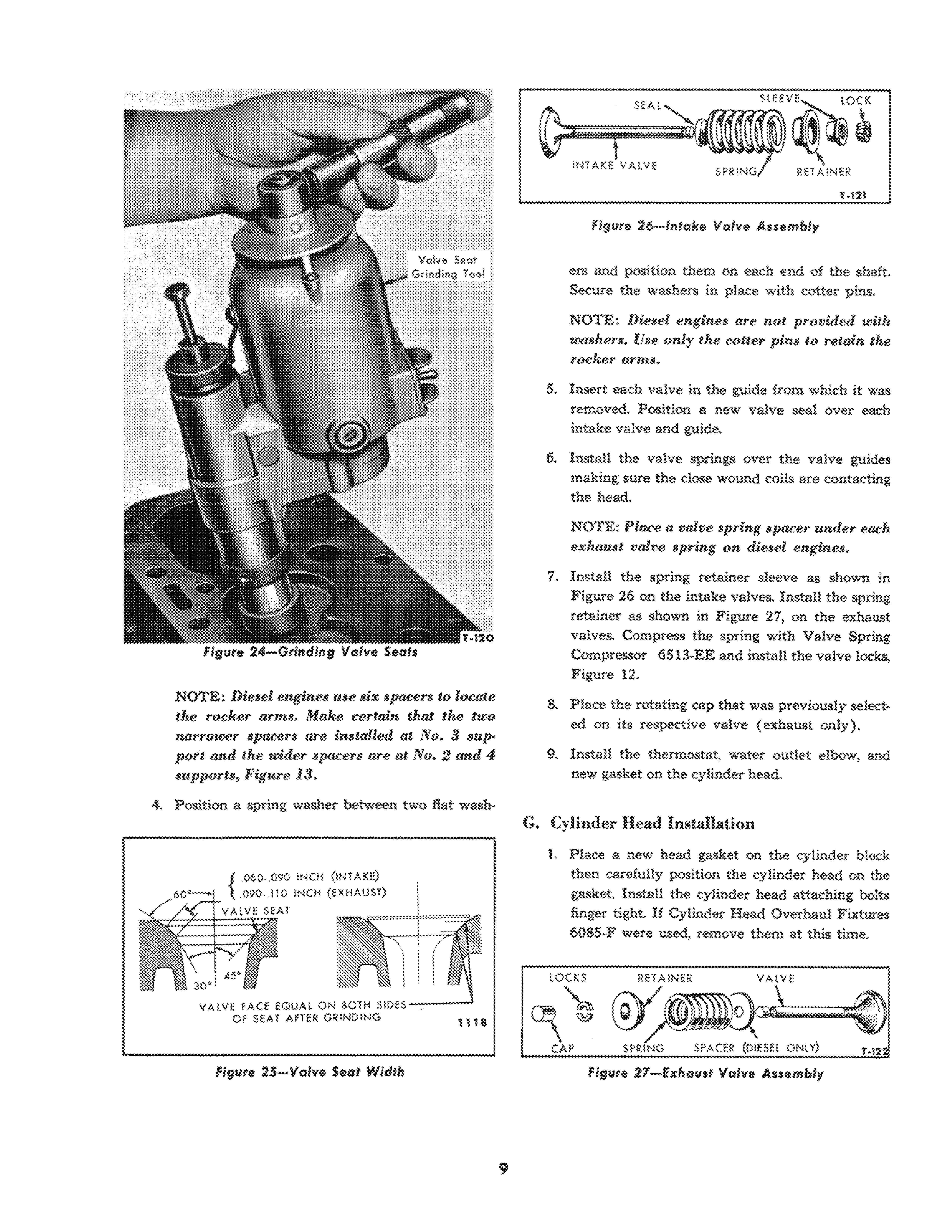
Grind the seat, as shown in Figure 24, only enough to remove all pits and grooves Of to eliminate an out of round condition. After refaeing, if the seat exceeds the width shown in FigUfe 25, it must be narrowed. Remove enough stock from the top of the seat (lower the seat) with a 60 " stone and enough from the bottom with a 30" stone (raise the seat) to make the width within specifications, Figure 25. Check the valve seat concentricity after the refacing operation.
The finished valve seat should contact the approximate center of the valve face circumference. To determine where the va lve seat contacts the face, coat the seat with prussian blue, then set the valve in place If the blue is transferred to the center of the valve face, the seat contact is satisfactory. If the hlue is transferred to the top edge of the valve face, lower the valve seat. If the blue is transferred to the bottom edge of the valve face, raise the valve seat.
F. Cylinder Head Assembly
1. Lubricate all moving parts with engine oil prior to assembly.
2. Apply sealer to two new rocker shaft plugs and install them in the shaft with a driver. Make sure that they are only in the shaft far enough to permit installat ion of the cotter pin..
3. Assemble the rocker arms, springs and brackets in the sequence shown in Figure 13,
1'\
Figure 21-Repladng Valve Guides
,/"//yl/
VALVE f{CE 40'
"\
VALVE SEAT 45"
INTERfERENCE ANGLE ON INTAKE AND EXHAUST VAlVES·l DEGREE
T-11'1
s
Fig"re 22-lnterferertce Angle on yalve Face
NOTE: Diesel engines use six spacers w locate the rocker arms. Make certain that the two narrower spacers arc installed at No. 3 suppott and the wider spacers are at No.2 and 4 supports, Figure 13.
4. Position a spring washer between two flat wash-
ers and position them on each end of the shaft. Secure the washers in place with cotter pins
NOTE; Diesel engines are not provided with woshers. Vse only the cotter pins to retain the rocker arms.
5. Insert each va lve in the guide from which it was removed. Position a new valve seal over each intake valve and guide.
6. Instan the valve springs over the valve guides making sure the dose wound coils are contacting the head.
NOTE: Place a valve spring spacer under each exhaust valve spring on diesel engines.
7. Install the spring retainer sleeve as shown in Figure 26 on the intake valves. Install the spring retainer as shown in Figure 27, on the exhaust valves Compress the spring with Valve Spring Compressor 6513-EE and install the valve locks, Figure 12.
8. Place the rotating cap that was previously selected on its respective valve (exha ust only).
9. Install the thermostat, water outlet elbow, and new gasket on the cylinder head.
G. Cylinder Head Installation
1. Place a new head gasket on the cylinder block then carefully position the cylinder head on the gasket. Install the cylinder head attaching bolts finger tight If Cylinder Head Overhaul Fixtures 6085-1" were used, remove them at this time
Figure 24-Grinding Valve Sea's{
060 ,090 INCH (INTAKE)
090 .,1]0 INCH (EXHAUST)
VALVE FACE EQUAL ON BOTH 5IDE5 -----1 OF SEAT AfTER GRINDING 1118
Figure 25-Vafve Secd Wid'"
RET AINtR
fig lire 26-1ntake Valve Assembly
Figllre 27- ExhOU$' Valve Assembly
TIGHTEN ROCKER ARM SHAFT !lOLTS 45·50 FT. UI$ TORQUE

TIGHTEN CYliNDER HEAD BOLTS 6510 fT. LS$ TORQUE t 240
figur e 28- Cylinder Head Tightening Sequence (Gasoline Engine sJ
2. Tighten the cylinder head bolts in the proper sequence and to the specified torque shown in Figures 28 and 29
Dies el Engines:
a. Install the four fuel injectors with new seat washers in the cylinder head. Torque the attaching bolts to 15-18 ft. Ibs. DO NOT USE A HAMMER TO SEAT THE INJECTORS.
b Install the excess fuel1ine and fuel injector lines.
c. InstaU the fuel filter on the cylinder head.
Gasoline Engin e s :
a. InstaU the spark plugs with new gaskets in the cylinder head
b Connect the spark plug wires to their respective plugs. The firing order is 1-2-4-3.
3. Install the push rods with the cupped end upward.
4 . Position the rocker arm in place on the cylinder head.
S. Install a new "0" ring on the oil inlet line. Install the inlet line in the cylinder block and rocker arm making sure it is free of the valve mechanism.
6 Install the rocker arm attaching bolts finger tight making sure that the ball end of the rocker arm adjusting screws are seated in the cupped end of the push rods Tighten the rocker arm attaching bolts evenly and alternately to 45-55 ft. Ibs. torque.
figure 30 - Valve Initial Adjustment Chart
7. Refer to Figure 30 and make an initial valve adjustment as indicated in the chart.
8 Install the intake and exhaust manifold and new gaskets. Connect the muffler to the exhaust manifold using a new gasket.
9. Connect the temperature gauge to the cylinder head.
10. Install the fuel tank. Install the air cleaner and tube Install the hood
11. Install coolant in the radiator
12. Start the engine and allow it to run until it reaches normal operating temperature.
13. Adjust the tappets to 0 014-0.016 inch clearance as shown in Figure 31 while the engine is running at idle speed.
NOTE: Later nwdel engines have a self-locking adjustment screw, while the earlier nwdels have an adjustment screw and rock nut .
14. Install the rocker arm cover and new gasket. Tighten the cover nuts to 20-30 in. lbs. torque.
10 fRONT e ee
®@@@ Of fNGINE crt . en, cn . eyc VALVE ARRANGEMENT CHART Valves Open Valves to be Checked $1 Cyt. Exhaust &: 3 Cyl. Intake #2 Cyl. Intake &: 4 Cyl. Exhaust It Cyt. Intake &: 2 Cyt. Exhaust
Figure 29 - Cylincler Head Tightening Sequence (Die sel}
(0@ E92) e
#3 Cyl. Exhaust &: 4 Cyl. Intake
$2 Cyl. Intake & 4 CyL Exhaust _1 Cyt. Exhaust &: 3 Cyt. Intake
$3 Cyl. Exhaust &: 4 Cyl. Intake #1 Cyt. Intake &. 2 Cyt. Exhaust
figu re 31 - Adjusting Valve Tappef Clearance
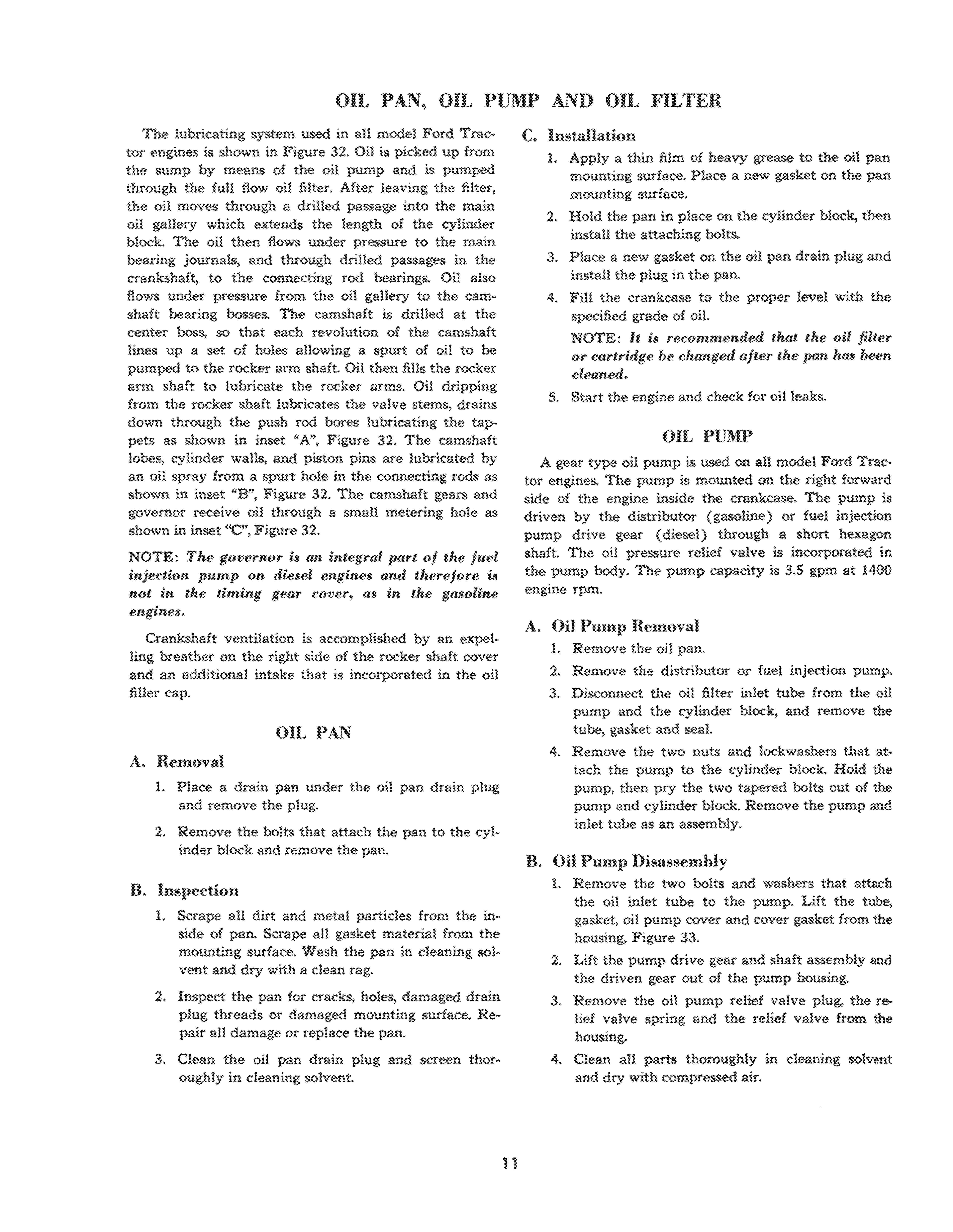
OIL PAN, OIL PUMP AND OIL FILTER
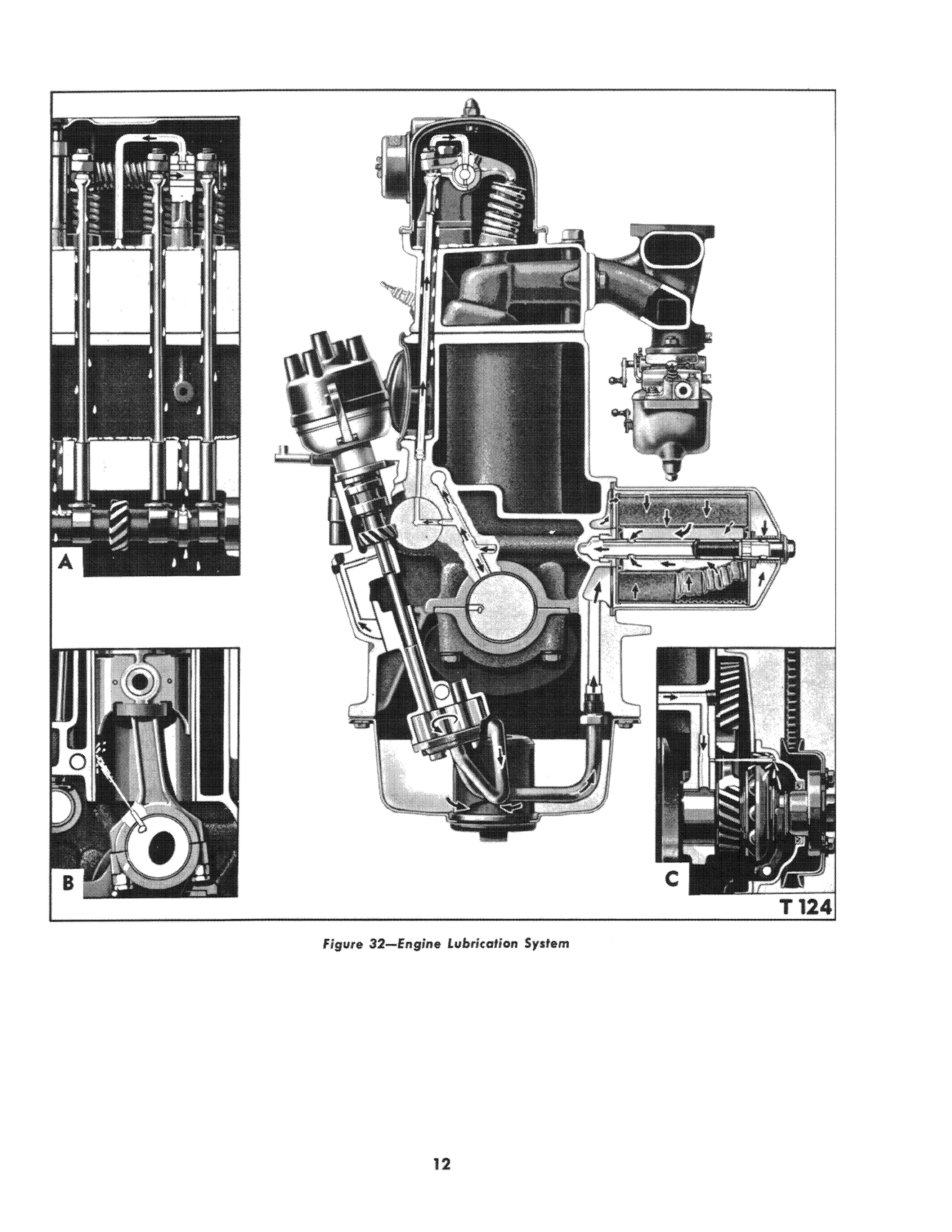
The lubricating system used in all model Ford tor engines is shown in F igure 32. Oil is picked up from the sump by means of the oil pump and is pumped through the fuU flow oil filter. After leaving the filter, the oil moves through a drilled passage into the main oil gallery which extends the length of the cylinder block. The oil then flows under pressure to the main bearing journals, and through drilled passages in the crankshaft, to the connecting rod bearings. Oil also flows under pressure from the oil gallery to the camshaft bearing bosses. The camshaft is drilled at the center boss, so that each revolution of the camshaft lines up a set of holes allowing a spurt of oil to be pumped to the rocker arm shaft. Oil then fills the rocker arm shaft to lubricate the rocker arms. Oil dripping from the rocker shaft lubricates the valve stems, drains down through the push rod bores lubricating the tappets as shown in inset "A", Figure 32 The camshaft lobes, cylinder walls, and piston pins are lubricated by an oil spray from a spurt hole in the connecting rods as shown in inset uB", Figure 32. The camshaft gears and governor receive oil through a small metering hole as shown in inset "e", Figure 32.
NOTE: The governor is an integral part of tlte fuel injection pump on diesel engines and tlterefore is not in tlte timing gear cover, as in the gasoline engines.
Crankshaft ventilation is accomplished by an expelling breather on the right side of the rocker shaft cover and an additional intake that is incorporated in the oil finer cap.
OIL PAN
A. Removal
1. Place a drain pan under the oil pan drain plug and remove the plug.
2. Remove the bolts that attach the pan to the cylinder block and remove the pan.
B. Inspection
1. Scrape all dirt and metal particles from the inside of pan. Scrape all gasket material from the mounting surface. Wash the pan in cleaning solvent and dry with a clean rag.
2. Inspect the pan for cracks, holes, damaged drain plug threads or damaged mounting surface. pair all damage or replace the pan.
3. Clean the oil pan drain plug and screen thoroughly in cleaning solvent. 11
C. Installation
1. Apply a thin film of heavy grease to the oil pan mounting surface. Place a new gasket on the pan mounting surface
2 Hold the pan in place on the cylinder block, then install the attaching bolts.
3. Place a new gasket on the oil pan drain plug and install the plug in the pan.
4. Fill the crankcase to the proper level with the specified grade of oil.
NOTE: It is recommended that the oil filter or cartridge be changed after the pan has been cleaned.
S. Start the engine and check for oi11eaks.
OIL PUMP
A gear type oil pump is used on all model Ford Tractor engines. The pump is mounted on the right forward side of the engine inside the crankcase. The pump is driven by the distributor (gasoline) or fuel injection pump drive gear (diesel) through a short hexagon shaft. The oil pressure relief valve is incorporated in the pump body. The pump capacity is 3.5 gpm at 1400 engine rpm.
A. Oil Pump Removal
1. Remove the oil pan.
2. Remove the distributor or fuel injection pump,
3. Disconnect the oil filter inlet tube from the oil pump and the cylinder blOCK, and remove the tube, gasket and seal.
4. Remove the two nuts and lockwashers that at· tach the pump to the cylinder block. Hold the pump, then pry the two tapered bolts out of the pump and cylinder block. Remove the pump and inlet tube as an assembly.
B. Oil Pump Disassembly
1. Remove the two bolts and washers that attach the oil inlet tube to the pump. Lift the tube, gasket, oil pump cover and cover gasket from the housing, Figure 33.
2. Lift the pump drive gear and shaft assembly and the driven gear out of the pump housing.
3 Remove the oil pump relief valve plug, the lief valve spring and the relief valve from the housing.
4. Clean aU parts thoroughly in cleaning solvent and dry with compressed air.
12
figure 32-Eflgine lubrication System
C. Inspection
1. Check the mating surface of the pump cover for wear. If the pump cover is visibly worn, scored, or damaged, replace it.
2. Check the pump housing for scores, cracks or damage and replace as necessary.
3. Check the gears for being chipped, broken or worn and replace as necessary.
4. Place the gears in the housing as shown in Figure 34. Place a straight edge on the pump body across the gears, then check the clearance with a feeler gauge. If the clearance exceeds 0.004", replace the gears and!or housing.
5. Check the clearance between the gear teeth and housing. If the clearance exceeds 0.005", replace the gears and I or housing.
6. Check the pressure relief valve spring tension. The pressure should be 9.76-9.84 Ibs. when com-
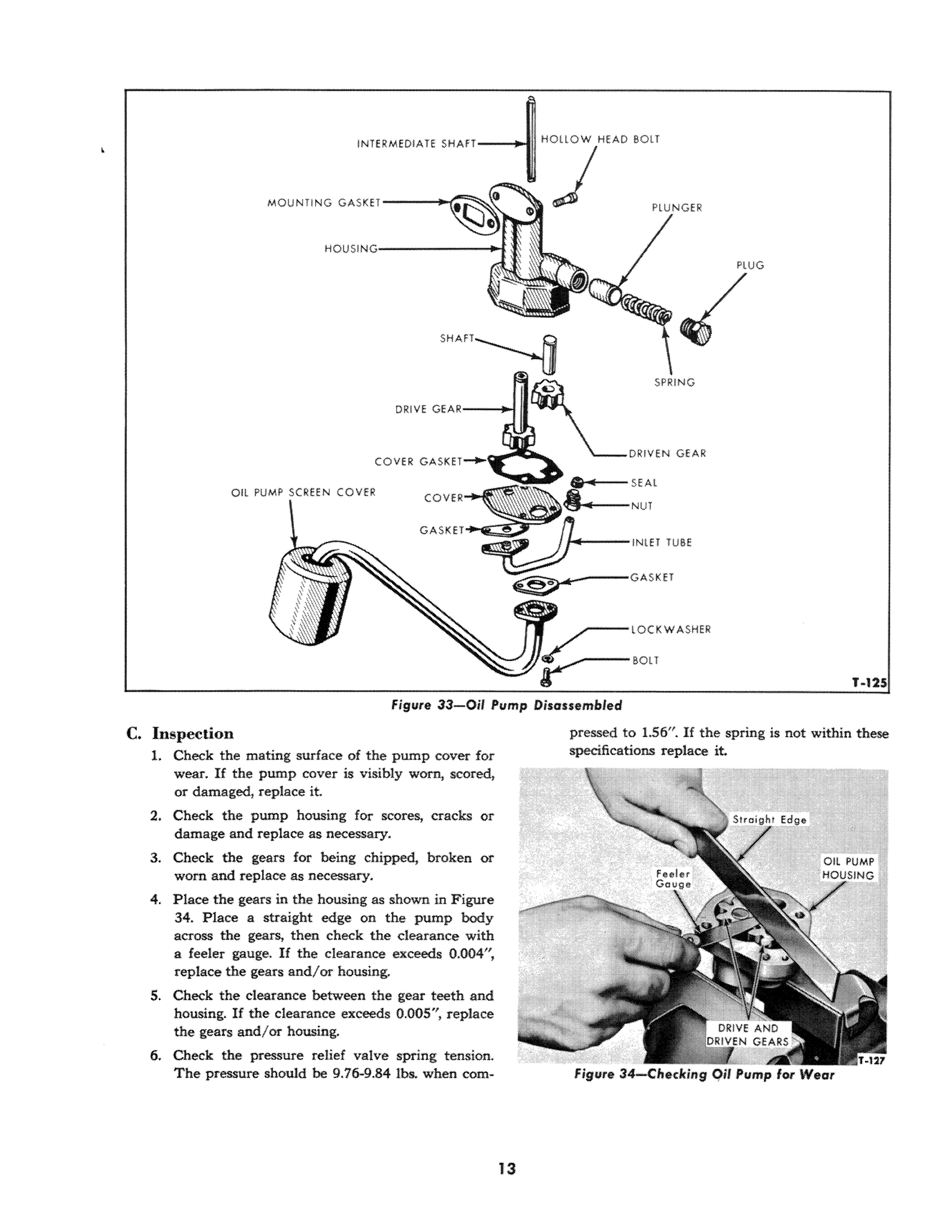
pressed to 1.56". If the spring is not within these specifications replace it
MOUNTING SPRING
DRIVE GEAR---to-i
N
/'""-- l OC K WASHER
OIL PUMP SCREE
COVER
T-125
Figure 33-0il Pump Disassembled
13
Figure 34-Checking Qil Pump for Weel
D. Assembly of Oil Pump
L Oil all parts with engine oiL
2. Install the pump relief valve plunger, spring and plug in the oil pump housing, Figure 33.
3. Position the drive gear and shaft and the driven gear in the oil pump housing.
4. Install a new cover gasket and place the cover and the oil inlet tube on the housing Install the two attaching bolts and lock washers.
5. Tum the drive gear shaft by hand to make certain that it turns freely,
E. on Pump Installation
1. Coat the pump housing to crankcase mounting surface with a light film of grease and position a new gasket on the housing
2. Secure the oil pump to the crankcase with two hollow head bolts, nuts, and lock washers. NOTE: The hollow head bolts are oj special design 1laving tapered shoulders. The bolt Iwads must be on the outside of the crankcase.
3 Connect the oil outlet line to the pump and cylinder block.
4. Install the oil pan
S. Install the distributor o r fuel injection pump.
6. Fill the crankcase to the proper level with the recommended oil. Start the engine and check for leaks.
F. Oil Pump Pressure Check
The engine oil pressure gauge indicates the pressure of the oil flowing to the bearings, but does not show the amount of oil in the crankcase. Oil in the crankcase can become dangerously low and pressure will stilI show on the gauge. Low oil pressure may be caused by a clogged oil pump screen, damaged oil pump, defective oil pressure relief valve, gauge, or worn bearings
1 Disconnect the gauge pressure line at the gauge and connect a master gauge in its place.

GASKET
lTHREADED CONNECTOR
Figure 31S-Later Type Oil filterDisassembled
2. After the engine has reached normal operating temperature, the oil pressure gauge should read approximately 4045 psi at 1400 rpm, and not less than 8 to 10 psi at engine idle speed (41S rpm). Oil is thick wben cold, therefore, oil pressure will be bigher than normal when the engine is cold.
3 As the engine speed increases, the oil pressure will increase until the relief valve opens, and decreases when engine speed is decreased. Extremely low oil pressure at engine idle speed (475 rpm) is generally caused by worn bearings or oil pump gears.
OIL FILTER
There are two different type oil filters used on Ford Tractor engines. One type consists of a cover, filter element, center bolt and relief valve and the attaching parts and gaskets, Figure 35. The other consists of a mounting insert, adapter, gasket and oil filter, Figure 36. The later type (Throw-Away) contains the relief valve in the filter, whereas the relief valve was in the center bolt on the earlier type.
Both fitters are of the fun flow type, meaning that all of the oil in the crankcase must flow through the filter befor e entering the engine lubrication system.
When the filter is operating properly, oil flows through the fi lter into the hollow tube or center bolt then into the main oil gallery. Under this condition, the pressure at both ends of the bypass va lve is equal, and the valve is closed. When the filter becomes dogged, pressure in the tube at the bottom of the valve becomes lower than at the top of the valve. When the pressure differential equals 7 psi, the valve opens, permitting the unfiltered oil to flow through the bypass valve and into the main oil gaUe ry.
A. Oil Filter Removal
1. Place a pan under tbe filter to catch tbe small amount of oil that will drip down. then remove the center bolt and pun the filter away from the engine.
SOLT AND VALVE ASSEMBLY OIL Fit RETAIN ING SPR ING Figul'e 3S- Early Type Oil Filt er- Disos:sembled14
2. Remove the filter element, gaskets and spring. Discard the dirty element and gaskets and wash the housing, center bolt and spring in solvent. If the engine is equipped with a throw-away type filter, turn the filter counterclockwise until free of the mounting insert and remove the filter.
3. Clean aU mounting surfaces thoroughly.
B. Oil Filter Installation
The oil filter used on row crop tractors is shorter than the one used on four wheel tractors, therefore, the cover and element are not interchangeable. The one throw-away type filter fits all model tractors equipped with a CPN-6882-A conversion kit The following chart shows the element and cover part numbers for each type of tractor: Tractor
1. Always use new gaskets when assembling the oil filter.
2. Assemble the filter for the four wheel tractors in the sequence shown in Figure 35. Assembly is the same for the row crop tractors, except that the bolt head is welded to the cover, making it one assembly.
IMPORTANT: Use only one gasket between the spring seat and the filter element. The use of more than one gasket may result in restriction 01 the bypass port.
3. Install the filter on the engine and tighten the center bolt to 20-50 ft. Ibs. torque. If the engine is equipped with the throw-away type filter, turn the filter onto the mounting insert until the seal
contacts the adapter then turn it one additional haH turn.
4. Start the engine and check for oil leaks. Check the oil level and add as necessary to bring the level to the "FULL" mark on the dipstick.
c. Throw-Away Type Oil :f'ilter Conversion Kit InstaUation
To convert from the early type oil filter to a throwaway type filter, proceed as fonows:
1. Place a drain pan on the floor below the oil filter area.
2. Remove the center bolt and valve assembly, cover and element, Figure 35.
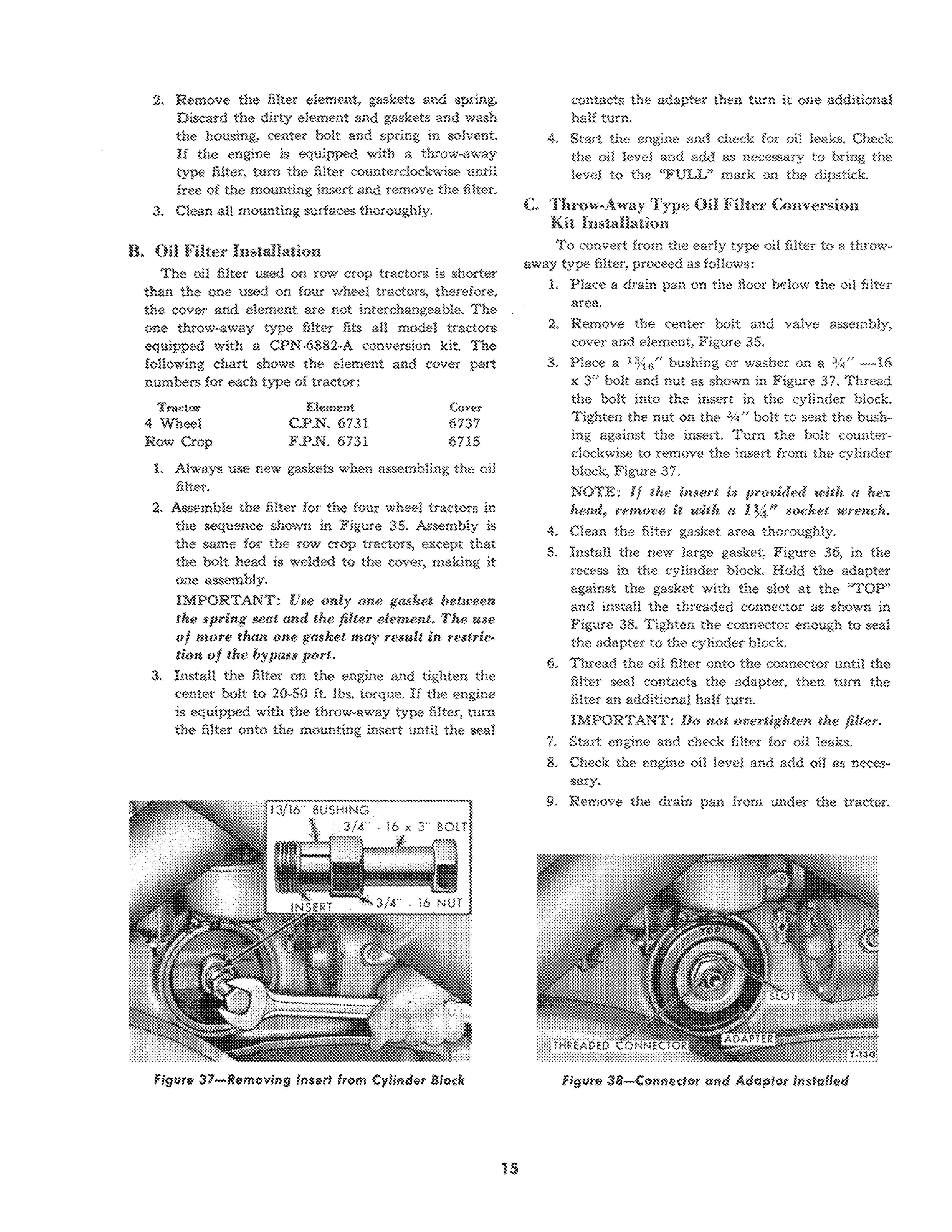
3. Place a 1%6/1 bushing or washer on a .l/4 1i - 16 x 3" bolt and nut as shown in Figure 37. Thread the bolt into the insert in the cylinder block. Tighten the nut on the .%" bolt to seat the bushing against the insert. Turn the bolt counterclockwise to remove the insert from the cylinder block, Figure .3 7.
NOTE: If the insert is provided with a hex head, remove it with a 1 *If socket wrench.
4. Clean the filter gasket area thoroughly
5. Install the new large gasket, Figure 36, in the recess in the cylinder block. Hold the adapter against the gasket with the slot at the "TOP" and install the threaded connector as shown in Figure 38. Tighten the connector enough to seal the adapter to the cylinder block.
6. Thread the oil filter onto the connector until the filter seal contacts the adapter, then turn the filter an additional haH turn.
IMPORTANT: DQ not o v ertighten the filter.
7. Start engine and check filter for oil leaks.
8 Check the engine oil level and add oil as necessary
9. Remove the drain pan from under the tractor.
4 Wheel Row Crop Element C P.N.6731 F.PN.6731 Covel" 6737 6715
15
Figure 37-Removing ins s rllrom Cylinder Block
Figure 3a-Connector and Adaptor Installed
CONNECTING ROD, BEARINGS, PISTONS, RINGS AND CYLINDER BLOCK
This section outlines the removal. inspection and installation procedures for connecting rods, pistons and pins. Complete data is given on the fitting of connecting rod bearings and the fitting of new rings, pistons and preparing the cylinder block for oversize pistons.
PISTON AND CONNECTING ROD ASSEMBLY
A. Removal
1. Remove the cylinder head and the oil pan from the engine.
2. Remove the ridge from the top of each cylinder with Cylinder Ridge Reamer 60 ll-E, see Figure 39,
NOTE: DQ not attempt to remove a piston and connecting rQd from the cylinder witlwut first remot1ing the ridge. Forcing the pistons past the ridge may break the lands on the pistons.
3. Remove the oil pump from the engine. If the engine is equipped with a balancer, remove it from the crankcase.
4. Turn the crankshaft until a piston is at the bottom of the stroke, then remove the nuts from the connecting rod bolts. Lift the rod hearing cap
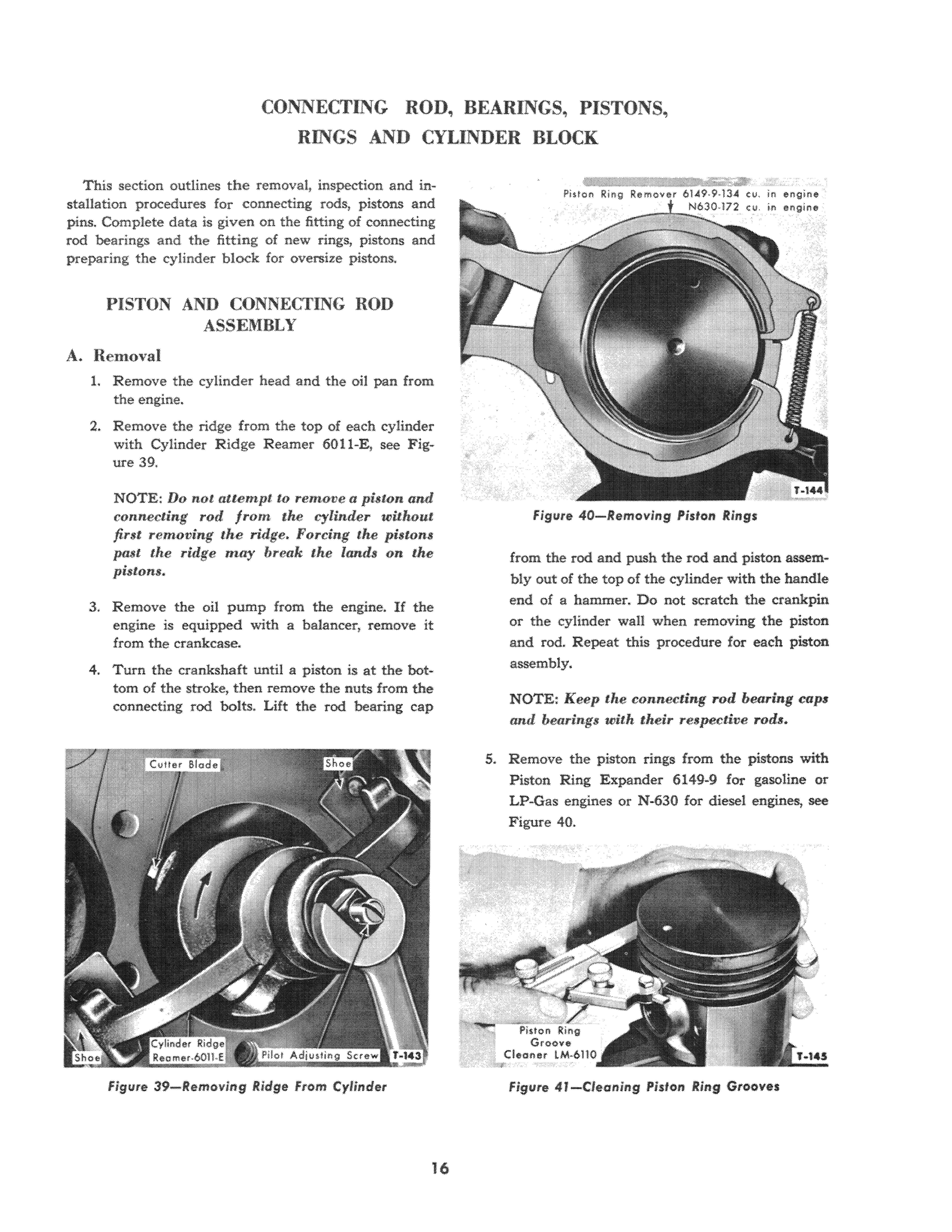
from the rod and push the rod and piston assembly out of the top of the cylinder with the handle end of a hammer. Do not scratch the crankpin or the cylinder waH when removing the piston and rod. Repeat this procedure for each piston assembly.
NOTE: Keep the connecting rod bearing caps and bearings with their respective rQd$.
5. Remove the piston rings from the pistons with Piston Ring Expander 6149-9 for gasoline or LP-Gas engines or N -630 for diesel engines, see Figure 40.
16
Figure 39-Removing Ridge .from Cylinder
Figure 40-Removing Piston Rings
in eogio$ i n e"gine
Figure 41-Cleaning Piston Ring Grooves
B. Cleaning
Clean the piston ring grooves with Piston Ring Groove Cleaner, LM-6110, Figure 41. Clean all the passages in solvent (do not use caustic cleaning solution) then dean the rod bore and the back of the connecting rod bearings thoroughly. Dry the parts with compressed air.
C. Disassembly
1. Mark each piston to make sure that it will be assembled on the rod from which it was removed. Remove the piston pin retainer from each side of the piston.
2. Drive the pin out of the piston with Bushing Driver Set 818.
D. Inspection
Connecting Rods:
1. Connecting rod bolts or nuts with damaged threads, and rods with deep nicks, signs of fractures, scored bores, or hores out of round more than 0.002", should be replaced.
2 Use a new piston pin to check the piston pin bushing in the connecting rod for wear. The pin should have a 0 .0001"-0.0003" clearance in the rod bushing. If a new pin falls through a dry bore by its own weight, replace the bushing and ream it to fit the new pin.
Connecting Rod Sea rings:
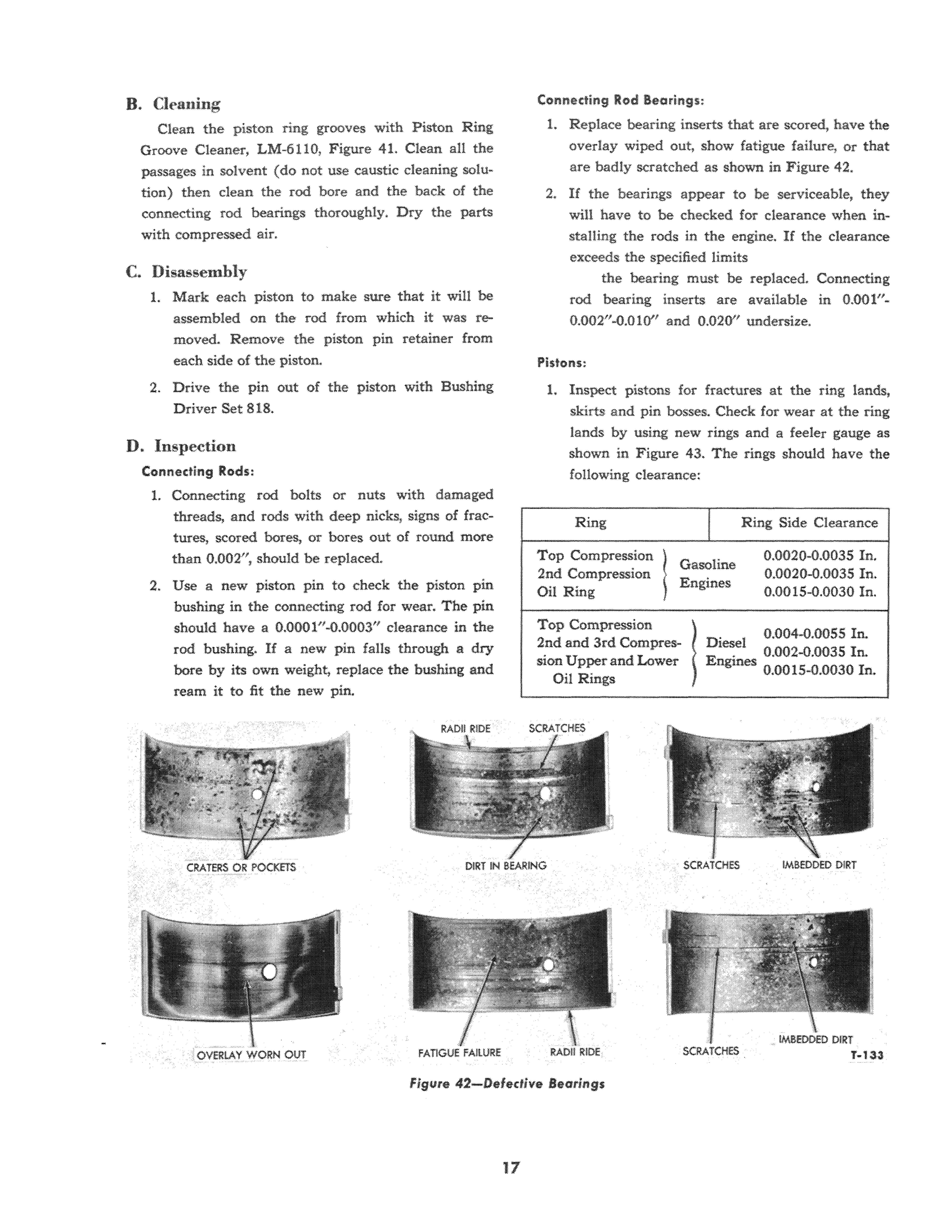
1. Replace bearing inserts that are scored, have the overlay wiped out, show fatigue failure, or that are badly scratched as shown in Figure 42.
2. If the bearings appear to he serviceable, they will have to he checked for clearance when instaHing the rods in the engine. If the clearance exceeds the specified limits the hearing must he replaced Connecting rod hearing inserts are available in 0.001"0.002"-0.010" and 0.020" undersize
Pis tons:
1. Inspect pistons for fractures at the ring lands, skirts and pin bosses. Check for wear at the ring lands by using new rings and a feeler gauge as shown in Figure 43. The rings shOUld have the following clearance:
Rings
Ring
Ring Side Clearance Top Compression IGasoline 0 0020-0.0035 In. 2nd Compression
0.0020-0.0035 In. Oil
0.0015-0
In Top
0.004-0.0055 In.
Diesel
0
sion
I
Engines
Ring
0030
Compression 1
2nd and lrd Compre&-
.
.002-0.0035 In.
Upper and Lower Engmes 0.0015-0.0030 In Oil
CRATERS OR POCKETS
DIRT IN BEARING SCRATCHES
17
Figure 42-Defective Bearings
2. Replace pistons showing signs of excessive skirt clearance, wavy ring lands, worn ring lands, tures or damage from detonation, Spongy, eroded
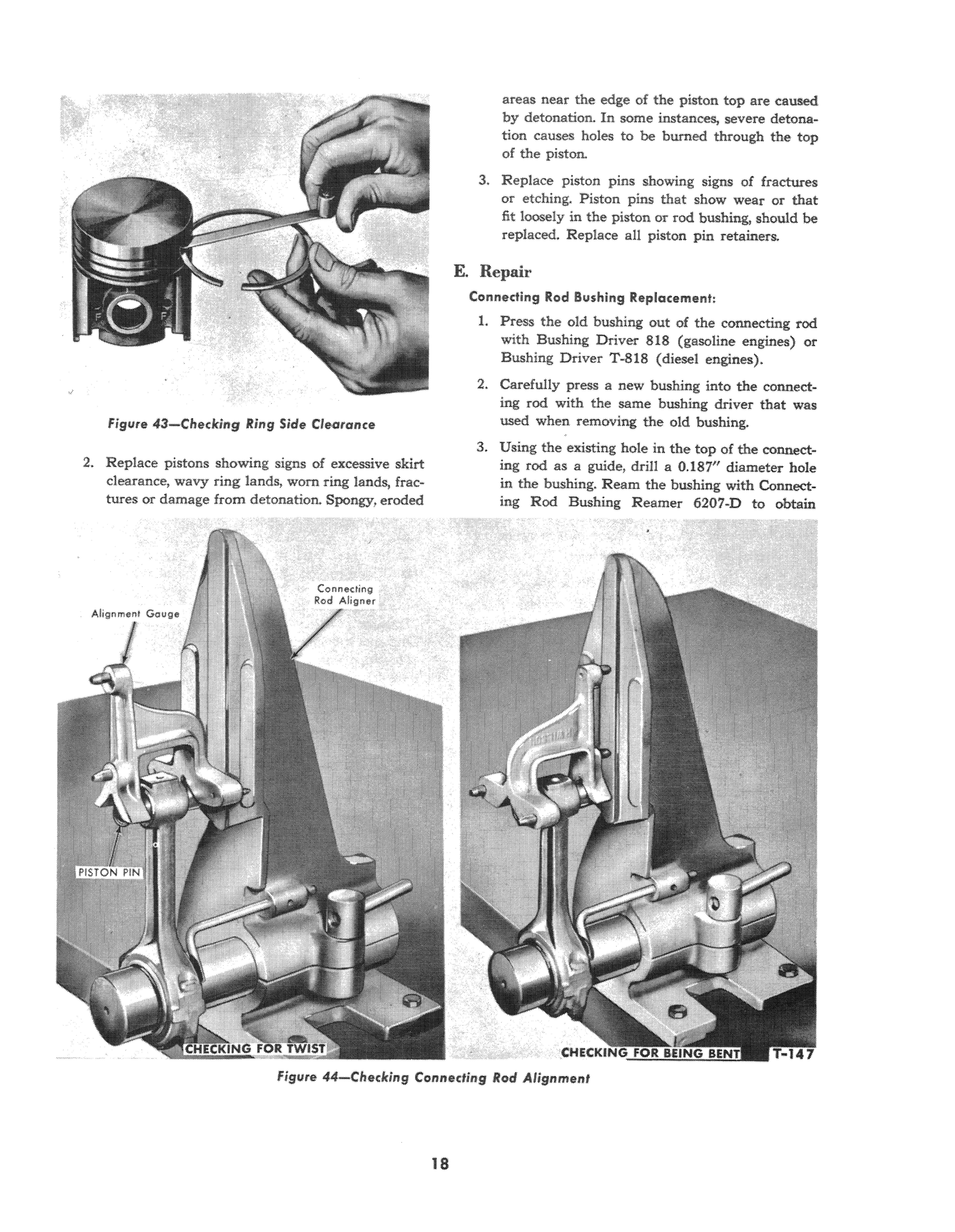
areas near the of the piston top are caused by detonation. In some instances, severe detonation causes holes to he hurned through the top of the piston.
3. Replace piston pins showing signs of fractures or etching. Piston pins that show wear or that fit loosely in the piston or rod bushing, should he replaced. Replace all piston pin retainers
E. Repair
Conn1l!ldll'lg Rod 8ushlng Replacement:
1. Press the old hushing out of the connecting rod with Bushing Driver 818 (gasoline engines) or Bushing Driver T-81B (diesel engines).
2. Carefully press a new bushing into the connecting rod with the same bushing driver that was used when removing the old bushing.
3. Using the existing hole in the top of the connecting rod as a guide, drill a 0.187" diameter hole in the hushing. Ream the bushing with Connecting Rod Bushing Reamer 6207·D to obtain
Figure 43-Checking Ring Side C1Hlrance18
Figure 44-Checking Connecting Rod Alignment
0.0(1)1-0.0003" clearance between the bushing and piston pin (gasoline engines).
4. Ream the bushings in diesel connecting rads to obtain a clearance of 0.0002-0.0008" with an expansion reamer.
Connecting Rod Alignment;
1. Place the connecting rod in an alignment fixture as shown in Figure 44.
2. If the connecting rod is twisted more than 0 012" or bent more than 0.004" it should be straightened or replaced.
Fitting Pistons:
1. Proper piston tolerances must be maintained if satisfactory engine operation is to be obtained.
2. Cylinder bores must be checked for taper and out of round condition before fitting a piston.
3. Before installing a piston and new rings in a used block, remove the high polish on the cylinder wall to aid ring seating, This is done by passing a hone or glaze removing tool through the cylinder bore a few times.
4. Do not hone more than enough to rough up the polish.
5. To fit a new piston in a new bore, attach Tension Scale, 3600·E to the end of a feeler ribbon Va"

Gop wide and having the correct thickness as outlined in the following tables.
Table I - Gasoline Engines
Fit New Piston Fit New Piston Fit Used Piston In New Bore In Used Bore In Used Bore
Gauge Gauge Gauge Thickness Pounds Thickness Pounds Thickness Pounds
Table II - Diesel Engines Fit New Piston Fit New Piston Fit Used Piston In New Bore In Used Bore In Used Bore
Gauge Gauge Gauge hickness Pounds Thickness Pounds (Inch) Pull (Inch) Pull 5-10
6. Position the feeler ribbon on the side of the piston 900 from the piston pin hole. Invert the piston, then push the piston and feeler gauge into the cYlinder so that the end is about %# below the top of the block. Keep the piston pin bores parallel with the crankshaft axis. Pullout the feeler gauge while noting the scale reading, see Figure 45.
19
figure 4S-Fittiog Pistolls
Figure 46- Clle(k10g Pl$lon Ring End
(Inch) Pull
Pull (Inch) Pull 0.0015 5-10 0.002 5-10 0.003 5-10
(Inch)
Thanks very much for your reading,
Want to get more information,
Please click here, Then get the complete manual

NOTE:
If there is no response to click on the link above, please download the PDF document first, and then click on it.
Have any questions please write to me: admin@servicemanualperfect.com