Part number 47969434
1st edition English November 2016
Replaces part number 47866576

Engine and crankcase
Pan and covers
V alve drive and gears
Cylinder heads
Connecting rods and pistons
[10.103] Crankshaft and flywheel
[10.210] Lift pump and lines
[10.206] Fuel filters
[10.218] Fuel injection system
[10.202] Air cleaners and lines
[10.250] T urbocharger and lines
[10.400] Engine cooling system
[10.414] Fan and drive
[10.310] Aftercooler
[10.408] Oil cooler and lines
10] Clutch and components
ransmission
[21.1 14] Mechanical transmission
[21.1 12] Power shuttle
10] Master clutch housing
Power shuttle transmission external controls
Gearbox external controls
Gearbox internal components
Creeper
Reverser unit
[21.200] Dropbox
Front axle system
Powered front axle
Front bevel gear set and dif ferential
Final drive steering and shafts
[25.400] Non-powered front axle
Rear axle system
[27.100] Powered rear axle
[27.106] Rear bevel gear set and dif ferential
Planetary and final drives
Power T f (PT
[31.1 14] T wo-speed rear Power T ake-Of f (PT
Brakes and controls
Mechanical service brakes
Hydraulic service brakes
10] Parking brake parking lock
Hydraulic systems
[35.000]
[35.104] Fixed displacement pump
Remote control valves
Main lift system
Steering
Steering control
Hydraulic control components
Cylinders
Wheels
Front wheels
Electrical systems
Electrical system
Harnesses and connectors
Engine starting system
Alternator
Battery
Electronic modules
External lighting
W arning and instruments
cab, and decals
[90.1 18] Protections and footboards
[90.1 14] Operator protections
Engine hood and panels
16] Fenders and guards

[10.001] Engine and crankcase .
Pan and covers
V alve drive and gears
[10.101] Cylinder heads
[10.105] Connecting rods and pistons
Crankshaft and flywheel
Lift pump and lines
Fuel filters
[10.218] Fuel injection system
Air cleaners and lines
[10.250] T urbocharger and lines .
and drive
[10.310] Aftercooler
Engine lubrication system
Oil cooler and lines

Engine - General specification
GENERAL SPECIFICA TIONS
V alve lift
T iner - Internal Exhaust Gas
opening (After BDC, during exhaust stroke)
valve closing (Before during Exhaust stroke)
cam lobe lift
valve lift (tiner)
V alve springs
V alve timing
Intake opening (before top dead centre)
Intake closing (after bottom dead centre)
opening (before bottom dead centre)
closing (after top dead centre)
V alve inserts
V alve guide
V alve guide oversize
V alve guide interference fit housing cylinder head
V alve guide fitted after reaming
V alve stem clearance guide
Crank gear
Crankshaft - Bearings
Crank pin diameter
Crank pin undersize
Crank pin clearance big end bearing
Width main bearing housing over thrust washers
Maximum main journal and crank pin ovality taper after grinding
Maximum main journal and crankpin ovality taper due wear taper due wear
Maximum main journal misalignment
Crankshaft resting end journals
Maximum misalignment crank pins relative main journals(in either direction) 0.25
T olerance from outer crankpin edge crank ‐ shaft center line ±0.10
Maximum crankshaft flange run ‐ out with gauge, over 108 (4.25”) diameter (total gauge reading)
Maximum flywheel seat eccentricity relative main journals (total gauge reading)
Connecting rods
Small end bore diameter
Small end bushing outer diameter
Bushing interference fit small end
Small end bushing
Maximum connecting rod axis misalignment 125 ±
Maximum connecting rod weight dif ference over a complete set from the same engine g
Pistons
Piston diameter: measured from base skirt and right angles pin
Piston clearance liner
Piston oversize range
Piston stand ‐ out with respect head T
Piston pin diameter
Piston pin seat bore piston
Piston pin clearance piston
Piston pin clearance small end bushing
maximum wear clearance
Maximum weight dif ference between pistons same engine g
Piston ring clearance groove
• T
• 2nd
• 3rd
Maximum wear clearance
• T
• 2nd and 3rd
Piston ring gap
• T
• 2nd
• 3rd
V alve gear
wear gap
V alve timing gears T iming
Idler gear bushing fitted after reaming
Jack shaft journal clearance bushing
Bushing interference fit idler gear
Lift and power steering pump drive gear shaft
Bushing fitted after reaming
Shaft clearance bushing
Bushing interference fit housing
Pump drive gear thrust washer thickness
Camshaft
Camshaft bushing
• Front
• Intermediate
• Rear Bushing interference fit housing
Camshaft bushing fitted I.D after reaming:
‐ Front
‐ Intermediate
‐ Rear
Camshaft journal diameter:
‐
T appets
T
V
Lubrication system
Gear housing depth pump bodyDrive and driven gear end float
Relief valve spring length:
Free ‐ A T load 134.55±6.73 N ‐ A T load N
Cooling system
W ater pump drive ratio
Shaft interference fit impeller
Shaft interference fit fan hub
Face sealing bushing interference fit impeller
Opening temperature
Close f temperature
V alve travel when fully open
Radiator V ertical tube and Aluminium fins Fan 6 blades
W ater temperature gauge Three colored sectors T emperature range for each sector: ‐ white sector
green sector
sector
Fuel pump drive Shaft journal dia
Bushing fitted after reaming
Shaft clearance bushing
Bushing interference fit housing
Inner washer thickness
Outer washer thickness
Injection pump
BOSCH
, integral governor and advance device 0460423063 (with LDA) ( 0460423072 ) With KSB 0460423073 With KSB 0460423079 (without LDA) (0460423076) Without KSB (0460423077) Without KSB (0460423075) With KSB (0460423078) Without KSB
Injectors:
Nozzle holder F002 C70 567 (KBAL P 163) F002 C70 567 (KBAL P 163 ) F002 C40 750 (DSLA 142 P 5565 ) F002 C40 738 ( DSLA 145 P 5544)
(delivery connection cylinder marked with letter
Engine - T orque
Engine - Sealing
SEALANTS
T iming Gear cover Dowel pin(S5)
Starter Motor Flywheel Housing (S6)
Allen Plug Cylinder Head Thermostat Housing (S7)
Cylinder Head Exhaust Manifold Studs (S8)
® 270 Oil Sump Engine Block (S9)
5900®
Silencer mounting Studs Exhaust Manifold(S10)
Flywheel Bolt (S1
Engine - Special tools
Engine - Overview DESCRIPTION AND OPERA TION
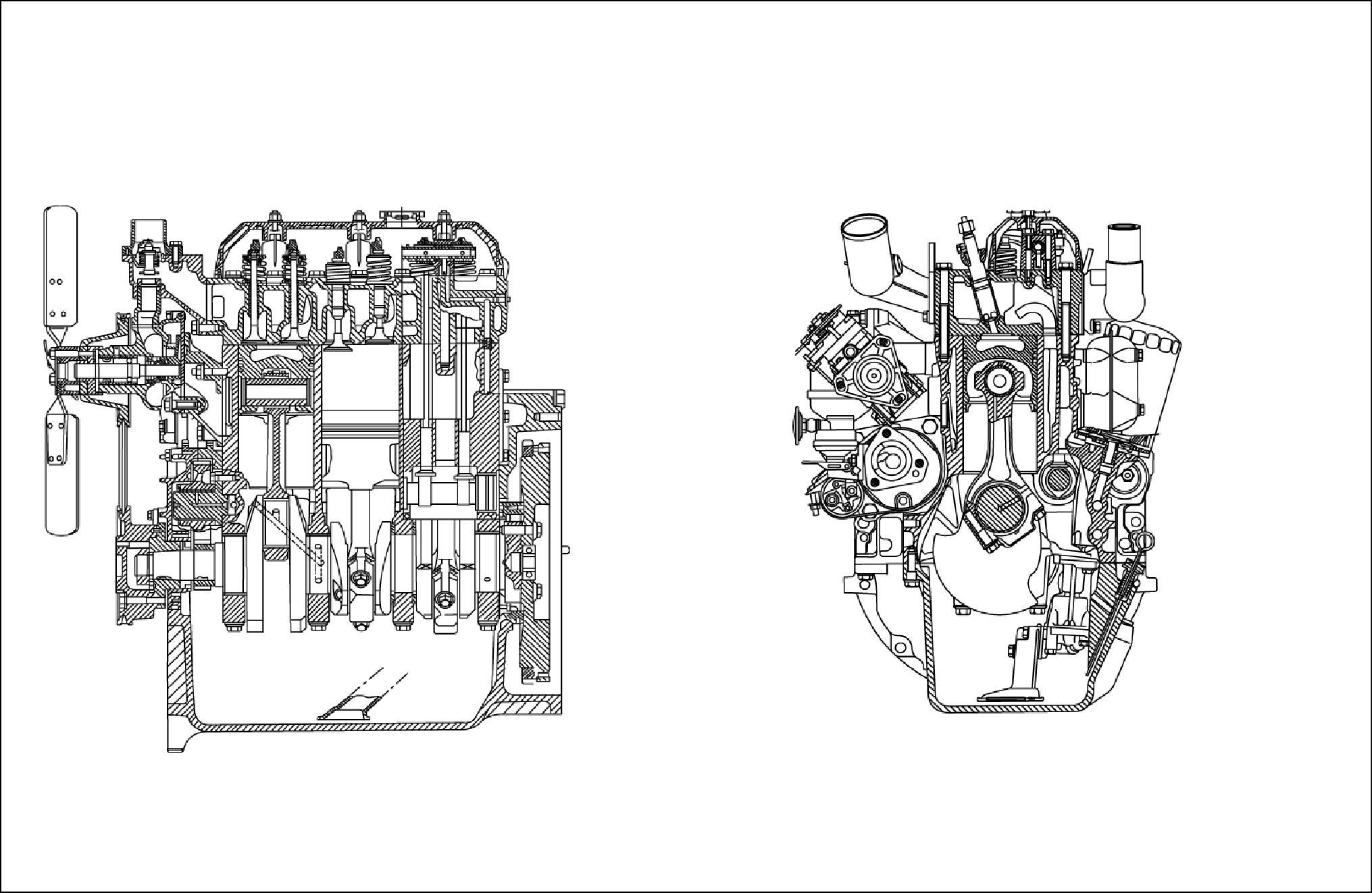
The engine a 3 cylinder engine with T urbo Charger and a inter ‐ cooler . This engine features cross flow cylinder with the inlet and exhaust manifolds opposite sides the cylinder The fuel and air combustion takes place the specially designed bowel the crown the pistons
CYLINDER HEAD ASSEMBL Y
The cylinder head consists valves and with the valve rocker arm shaft assembly bolted the cylinder block through the cylinder Cylinder head retaining bolts are evenly spaced with a six ‐ point pattern around each cylinder; this ensures even clamping load across the cylinder The intake and exhaust manifolds are bolted the head; the intake manifold mounted the right side the engine, with the diesel injectors mounted outside the rocker cover The exhaust manifold mounted the left side the W ater outlet connections and thermostat being attached the front the cylinder block directly behind the radiator V alve guides are inserted into the cylinder and Special replaceable cast alloy valve seats are pressed into each valve port during oversize valve seats guides are All valves are fitted with positive value rotators; valve clearance maintained adjustment the self locking adjusting screw , mounted each the rocker
CAMSHAFT ASSEMBL Y
The camshaft runs 3 replaceable bushes. The camshaft drive gear mesh with and driven the camshaft idler gear which driven the crankshaft timing gear Camshaft end thrust controlled a thrust plate bolted the and located between the camshaft gear and the front camshaft A helical gear integral rear cam shaft, and drives the engine oil lubrication pump mounted forward the flywheel.
Cylinder block assembly
The cylinder block alloy cast iron with deep cylinder skirts & water jackets for cooling the The cylinder bores are machined integral with the cylinder during the manufacturing Cylinders are inline and vertical and numbered from 1 3 from front the engine the rear The oil which attached the bottom the cylinder the reservoir for the engine oil lubrication A cast iron engine front cover and front plate attached the front the engine and covers all the timing gear assembly
CRANKSHAFT ASSEMBL Y
The crankshaft supported the cylinder block 4 main The crankshaft manufactured from steel with machined finished crank webs, End thrust controlled a thrust bearing. A dynamic balancer fitted and driven crankshaft ensure smooth running Front and rear crankshaft oil sealing fected one piece seals that are designed for long and durable service
CONNECTING RODS
The shaped the small end the connecting rod has been designed reduce the reciprocating weight the piston The connecting rods have a heavy beam construction and are assembled a matched set each They are attached the means insert type They are retained position the connecting rod big end cap and secured two bolts per rod. The small end the connecting rod fitted with a replaceable bronze through which the free floating piston pin The steel pin being held place within the piston two snap
PIST ONS
Pistons are constructed aluminium silicon alloy with notch type combustion chamber being recessed the piston
Each piston has two compression rings and one oil control reduce the friction and increase positive All rings are located above the piston pin.
Manifolds
The cross flow design aluminium intake, and cast iron exhaust manifolds are opposite sides the cylinder head. This designed maintain balanced heat distribution within the cylinder The configuration the manifolds
also ensures minimum heat transfer the intake The intake manifold connected through hose air cleaner

A 1
T iming gears
The crankshaft timing gear heated and press fitted the front the a high degree accuracy during This enables precise timing being maintained during the life the The crankshaft gear drives the idler gear , which attached the front cylinder block. The idler gear then drives the camshaft and the injection pump via meshing helical gears
The camshaft gear bolted the front the shaft and keyed maintain position the gear the
LUBRICA TION SYSTEM
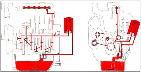
Lubrication the Figure 7 & 8 maintained a gear type oil pump mounted the rear the engine forward the flywheel the left hand side viewing from rear side the The oil pump driven from the rear the camshaft and drains oil from the engine oil sump through a tube and screen assembly
A spring loaded relief valve integral with the oil filter and prevents over pressurization the A spin type oil filter mounted externally its support housing the left hand side the engine. Oil flows from the filter the main oil gallery , which runs the length the cylinder which also intersects the camshaft follower chamber
The main gallery also supplies oil the crankshaft main connecting rods both big and small ends and timing gear The underside the pistons and pins are lubricated oil pressure
T iming gears are lubricated splashed oil from the cam follower chamber and the pressure lubricated camshaft drive gear
intermittent flow oil directed the value rocker arm shaft assembly via a drilled passage the cylinder This located vertically above 3 camshaft bearing and aligns a hole the cylinder The rotation the camshaft allows a controlled intermediate flow

COOLING SYSTEM
The function the water pump mounted the front the maintain a continuous flow water around the cooling This essential ensure engine temperature and performance within the recommended during vehicle
The W ater pump driven a ‘V’ belt the crankshaft pulley , when the engine
The cooling system for the new generation engines recirculating ‐ pass type with full length water jackets for the bottom tank the radiator the water which passes the coolant the cylinder This coolant then flows through cored passages cool the cylinder walls.
Passages the cylinder head gasket allow coolant flow from the cylinder into the cylinder head cored passages also conduct the coolant the fuel injector nozzle locations before ‐ entering the water pump below the thermostat
The thermostat located the top the water pump body , and controls the flow the water required perature

NOTE: If there is no response to click on the link above, please download the PDF document first, and then click on it. Have any questions please
