

Portfolio
abhishek Ray
Abhishek Ray
I am a passionate architect (Bachelor of Architecture, 2014) with seven years’ work experience in various sectors in the AEC industry, having worked in major projects in India, UK, UAE, Bangladesh etc.
I have worked at BDP., one of Europe’s leading multidisciplinary practice, for seven years, and then at SpaceMatters, awarded India’s second best architecture firm by Architizer.

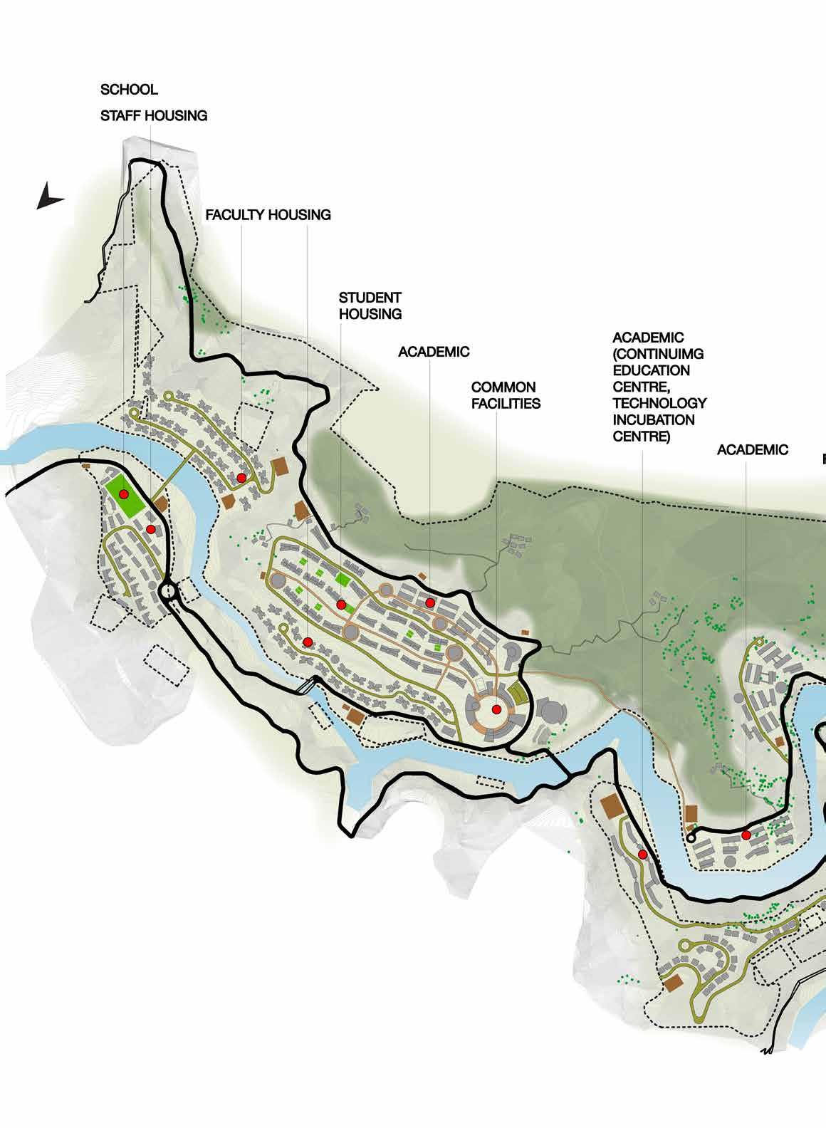
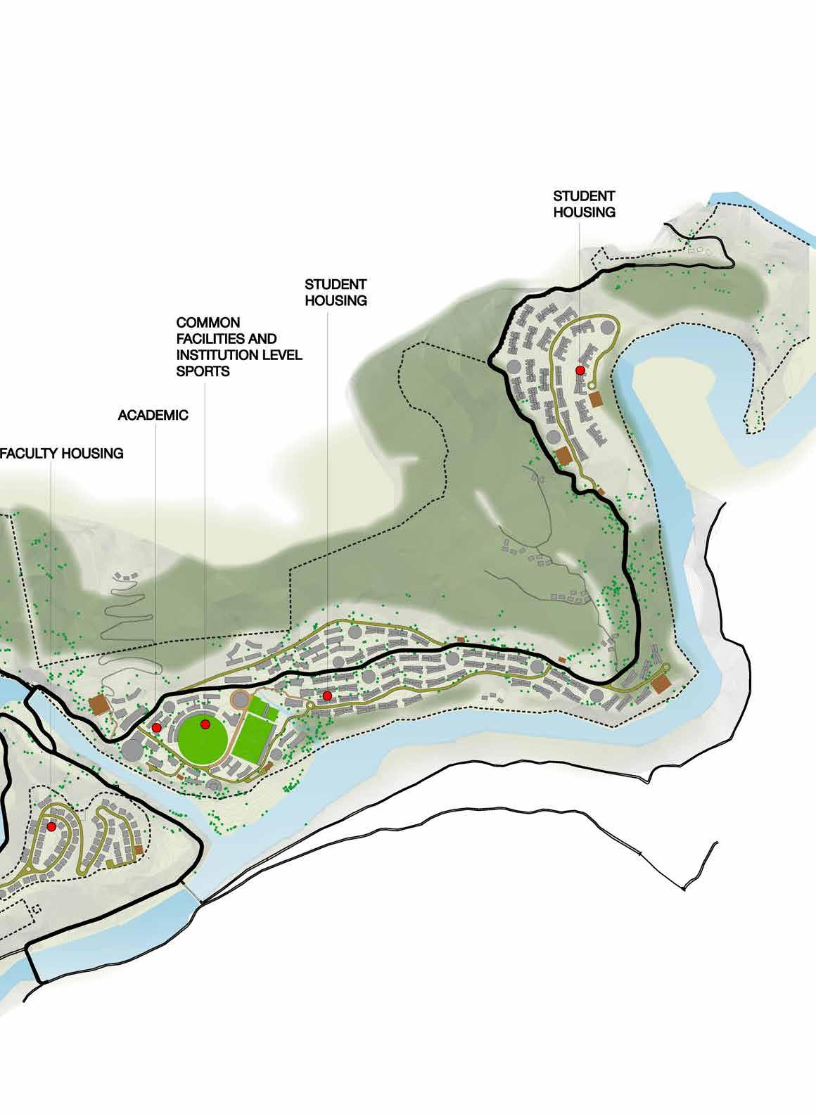
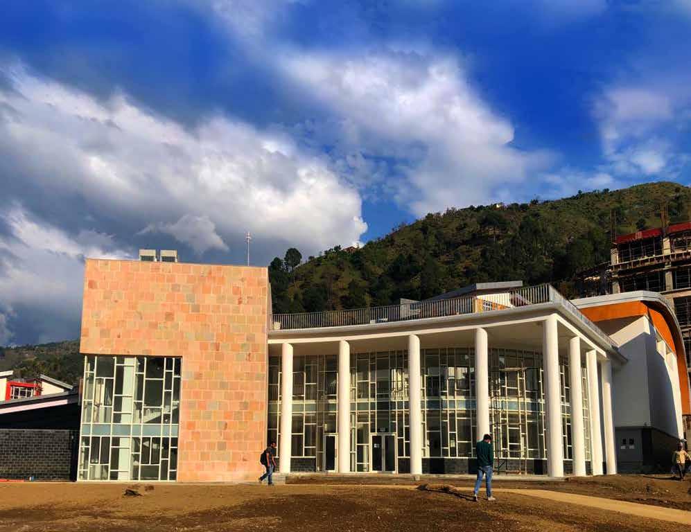
IIT MANDI, HIMACHAL PRADESH EDUCATION
IIT Mandi campus, Himachal Pradesh, India
IITMandi is a part of the extensive West Himalaya Biogeographic Province. The Campus falls within one of the upland watersheds of the river Beas.
The new campus will be a physical manifestation of the

aims, ambition and character of IIT Mandi. The built form will need to be designed to become a beacon of engineering excellence which is inspiring and sensitive to its natural surroundings, together creating a place which will leave a very strong impression on everyone who will live, work or visit.
4 SITE
KEY FIGURES:
Project:
Site Area:
Built up area:
Built up area
(Use Wise- All Phases):
Supported Population:
IIT, Mandi
538 Acres (200 acres developable)
9400 sqm- Phase 1A (2012)
116800 sqm- Phase 1B (2015)
422700 sqm- Phase 2
Academic- 124600 sqm
Residential- 344113 sqm
Common Facilities- 14920 sqm
6200 Students
620 Faculty (with families)
1040 Support Staff
5
THE SCHOOL & HOSTEL

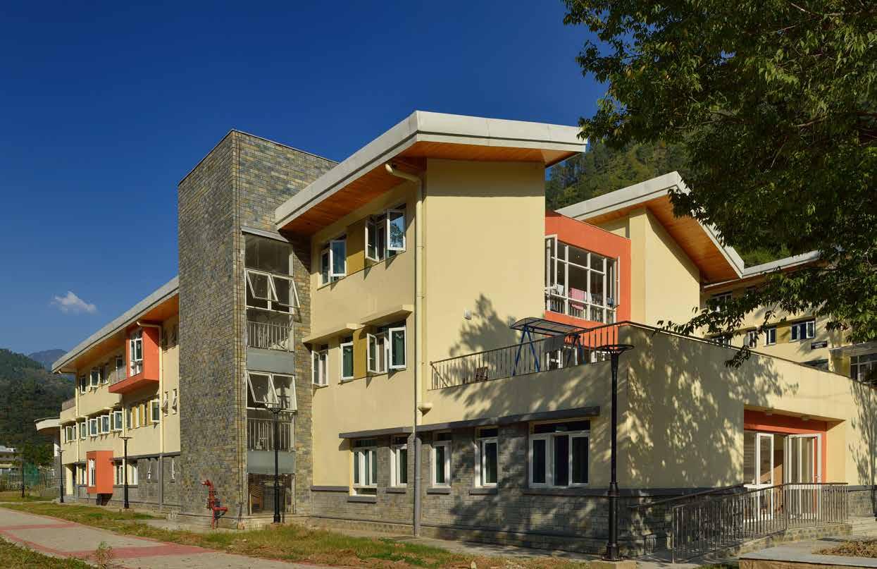 The school in the campus
Student hostel
The school in the campus
Student hostel
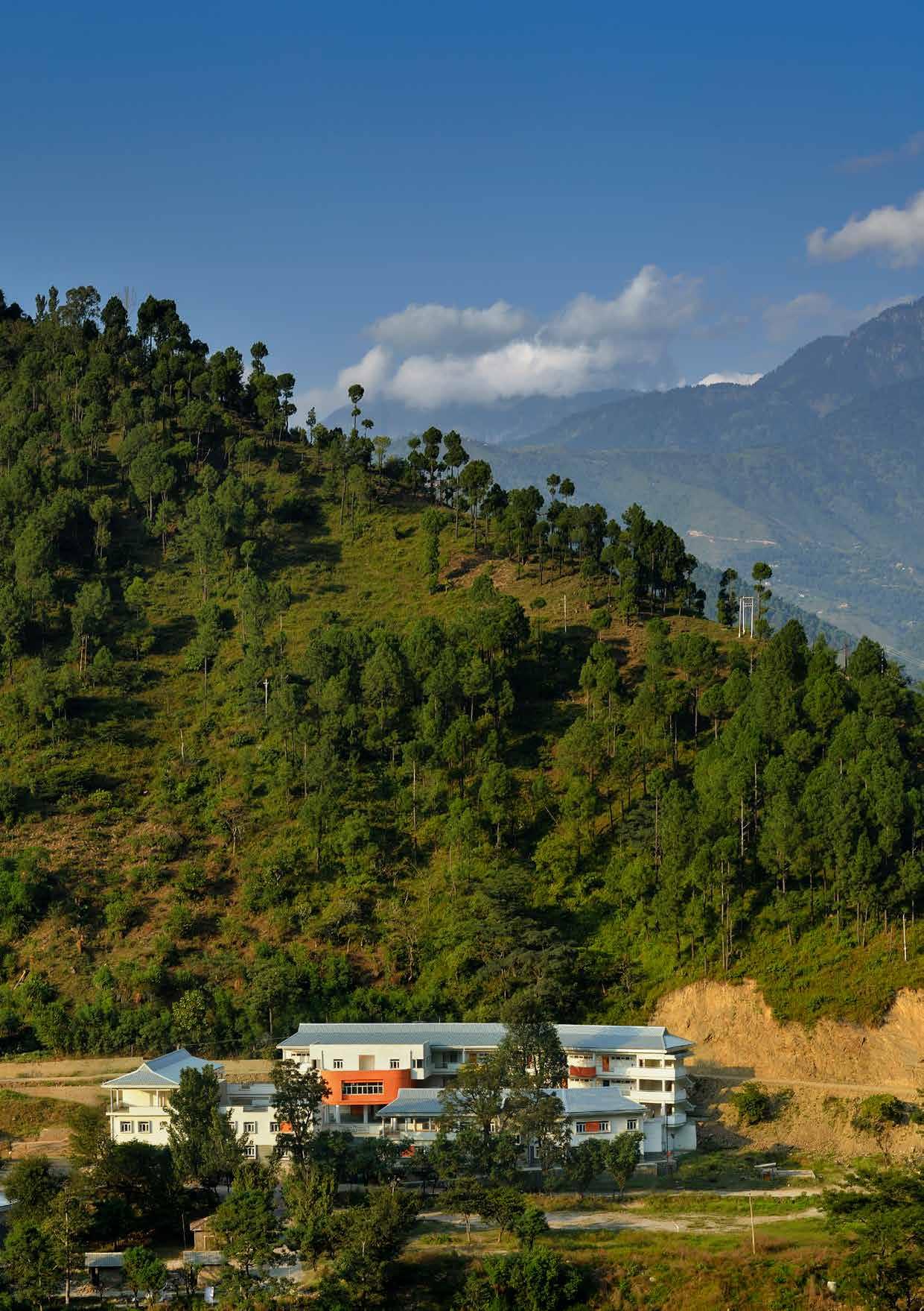
View of the school
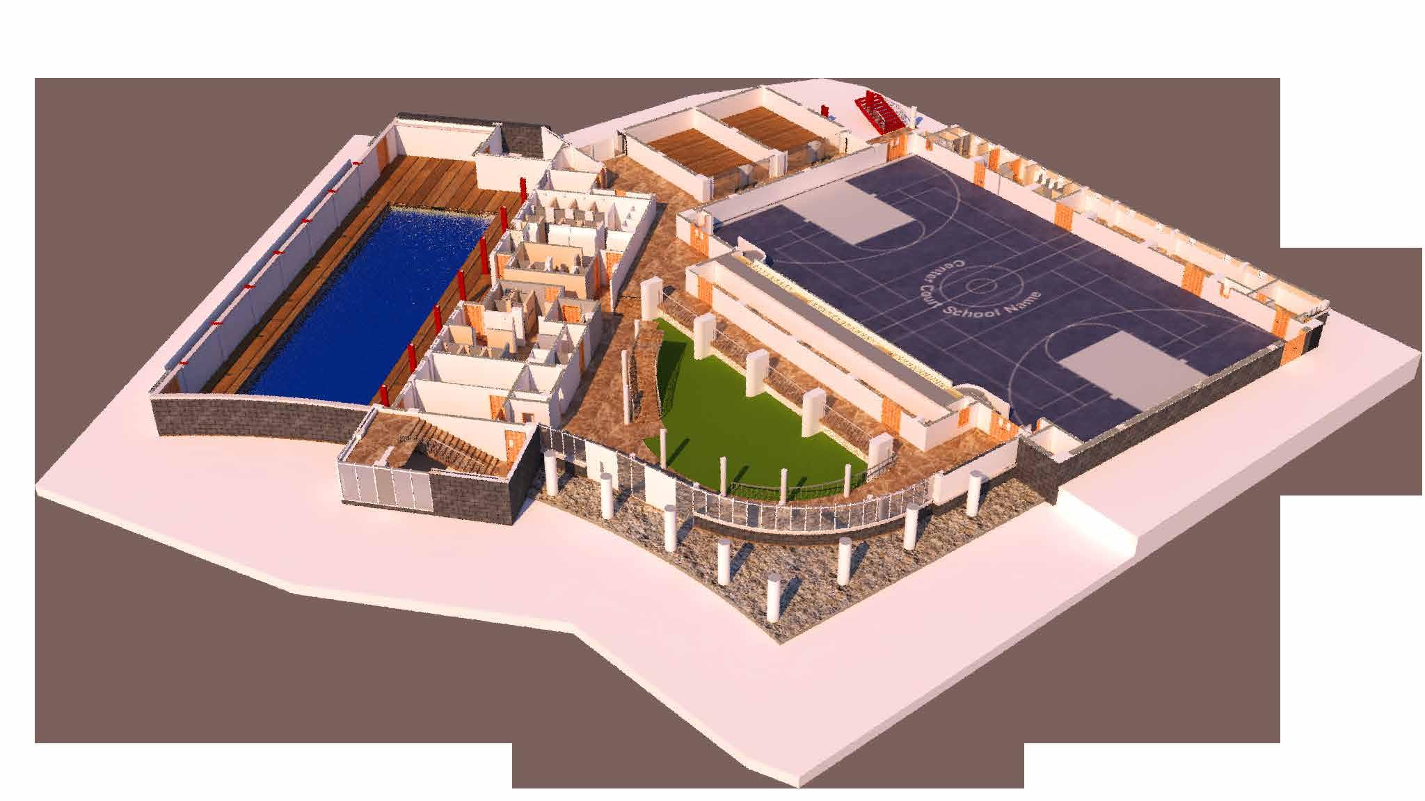
THE GYMNASIUM
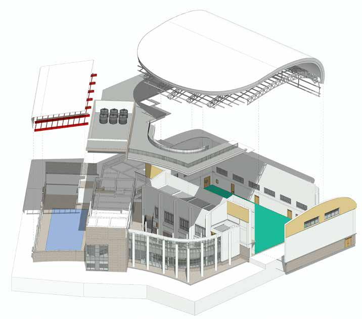
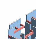
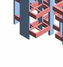
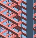
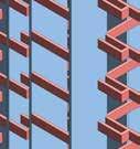
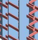
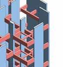
The gymnasium is one of the more interesting structures in the site.
It is part of a non-academic space, dubbed ‘The Market Square”.
The gymnasium boasts a basketball court, a swimming pool, a squash court, among other things.
8
Blow-up view of the gymnasium
9 Toilets Store Sports hall Entrance Changing rooms Swimming pool Squash court Indoor landscape Seating Gymnasium ground floor Ground floor plan 37 F V V 35 21 20 19 FFL -1350 mm Filtration/ Plant Swimming Pool 2 R R 36 32 30 27 25 23 S U T T 2 A6 21)AS05 1A6(21)AS050 A6(2 )AS0 0 2 6(21)AS050 1 35 00 Staircase#4 W 1500 00 60 00 200mm Deep 20 4 3 1 37 F F A B V V Q Q M 35 38 21 20 19 C E D 15 13 7 2 22 C ELEC 1 BASKETBALL/ BADMINTON COURTS Spectator Ladies changing room Office Toilet A6.00.7a Showers A6.00.7c Dry Changing First aid Room A6.00.09 Pool 4 Lanes (25m X 8m) A6.00.18 Indoor Landscaped area EL C HAFT Secondary entry Staircase#4 4 6 ) 1 2 1 E 5 am p 2 G Store A6.00.03 26 24 D20 D12 D14 ED3 D18 D12 D12 D17 D20 D20 D20 D20 D20 D20 D20 D14 D14 ED1 ED1 D12 D17 D12 D20 1 10 11 9 12 17 5 14 N R R L 36 32 30 27 25 23 29 33 34 S 16 U T T 9 5 2 7 00 00 00 00 50 W3 W21 W21 W21 W21 W21 Staircase #2 300 150 W = 2050 W3 2 A6 21)AS05 A6(2 )AS0 0 A6(2 )AS050 4 A6(21)AS051 4A6(21)AS051 3 A6( 1 AS051 3 A6(21 AS051 3 00 UP W 1500 6800 GL37 P P M3 M5 M6 M1 M2 7 J K 15 30 10 40 3 0 Party area/ Seating A6.00.19 Squash court A6.00.11 Squash Court Ladies toi. A6.00.15 Gents toi. A6.00.16 Corridor A6.00.10 Entry Lobby Dry changing A6.00.4b Showers A6.00.4c Gents Changing Room A6.00.07 A6.00.7b GL32b GL38 5 31 1 W3 W3B 60 +2550 mm R = 150 W 1200 NOTE: COURT MARKINGS 15 NOTE: COURT MARKINGS SHALL BE AS PER FITOUT DETAIL VENDOR NOTE: COURT MARKINGS SHALL BE AS PER FITOUT U UP SSL +850mm 1 3 A6(21)AP001 2 A6(74)AD002 33A UP 50 T = 300 R = 150 W 1200 T = 300 R 150 8 10 5 A6( AS051 30 30 20 0 0 1 W23 +1950 mm +1950 mm m 10000 0 18 W20 M4 ROM TH CE ER OF MARK Ra iu 39200 Ra 1000 1 G1 00 Railing as/detail 6800 61 7 0 15 70 (As per landscape details) 10 D20 2 0 0 5 W24 W24 Sunshade as/detail H 0 Cavity wall with Cavity wall without Cavity wall without 4 A 7 9 5 8 10 Ladies toi. 100 D20 D12 600 100 900 200 1850 850 130 130 950 150 950 200 1050 975 590 W20 Towel hanger As/BOQ Tile Drop Tile Drop 300 150 NOTES @ A0 20 Green Park (Main) New Delhi 110016 +91 (0)114 333 7333 www.bdp.com 408 Regent Chambers 208 Nariman Point, Mumbai 400021, India Phone: +91 22 40020658 2284 0284 Fax.: +91 22 40021658 www.ucjain.com Frischmann Prabhu (India) Pvt. Ltd. CONSULTANCY, DESIGN, ENGINEERING, PROJECT MANAGEMENT 315, Balgovind Wadi, New Prabhadevi Road, Email: pfmumbai@pellfrischmann.com ENGG. CONSULTANT GOOD FOR CONSTRUCTION WORKING DRAWING •ANY DRAWING ERRORS OR DIVERGENCIES SHOULD BE BROUGHT TO •FOR ALLIGNMENT OF OF EXTERNAL WALLS, REFER EXTERNAL WALL RESPECTIVE (74) AND (73) SERIES DRAWING. As indicated IIT Mandi Phase- 1(North) Institutional Facilities P8100022 Gymnasium A6 A6(21)AP001 R0 29/02/16 1 100 Level Pool 2 1 100 Level 00 1 1 25 Toilet T1 1A
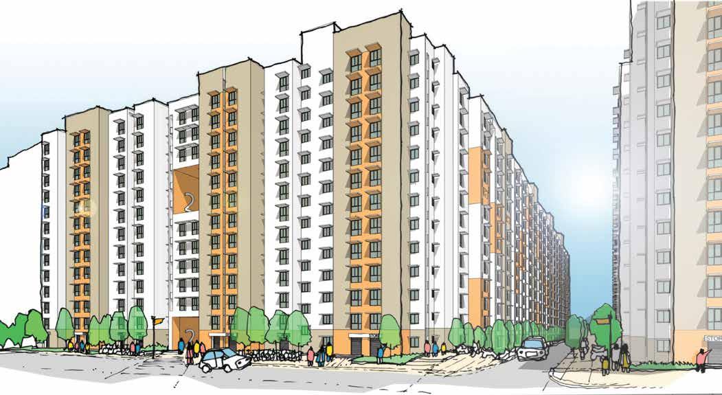
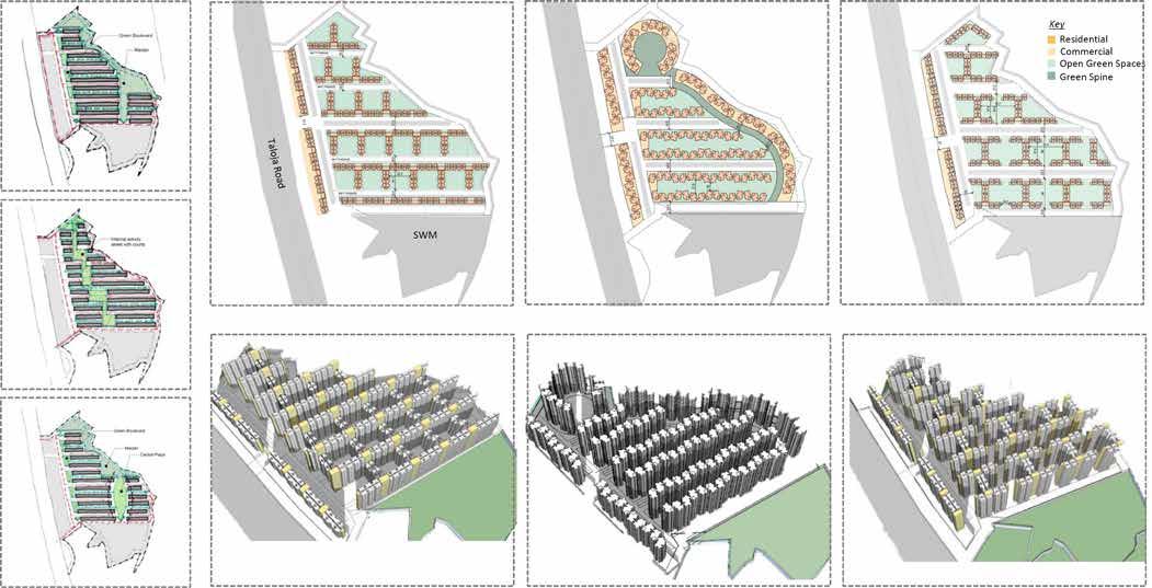
LODHA SOCIAL HOUSING, MUMBAI
Lodha
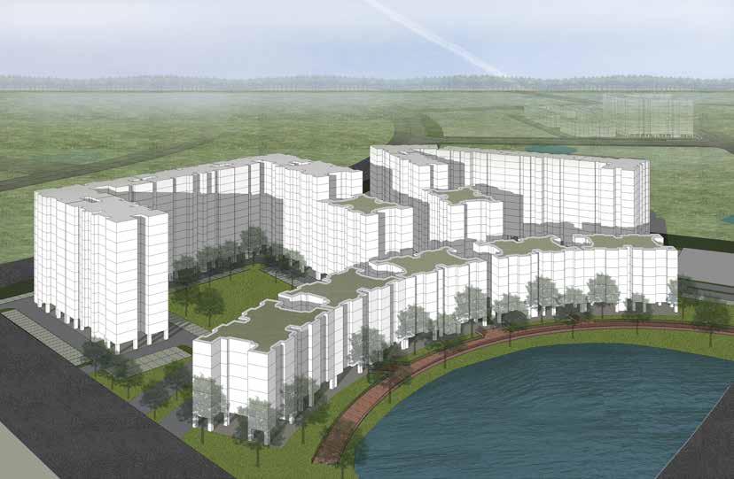
Social Housing in Palava is a combination of differently-sized 1 BHK apartments to be handed over to MHADA (Maharashtra Housing
and Development Authority). The site spreads over 29.72 acres with an overall built up area of 5,23,663 sqm. The apartments have been designed as prototypes which are repeated across the site to ease prefabrication methods of construction.
This would help save time, keep
construction cost-efficient, and result in an affordable yet functionally well-designed product.
Currently two pockets have been constructed. The rest of the pockets are being simultaneously designed, as the completed ones are being prepared to be handed over.
10
AFFORDABLE HOUSING
Masterplanning options
Concept sketch
11
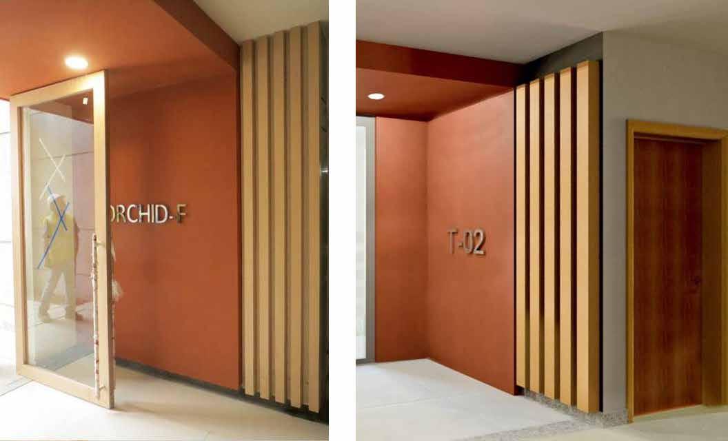
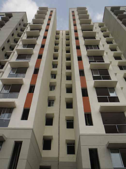
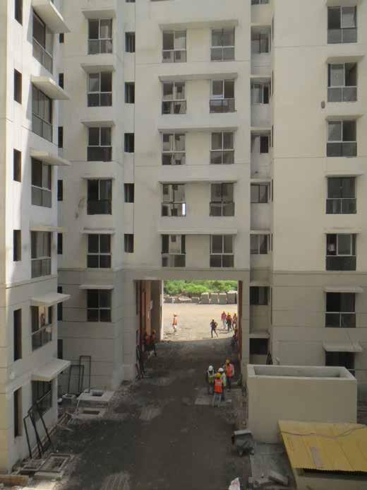
SITE PHOTOGRAPHS
Entrance lobby as built
Entrance lobby rendered concept
Tower view (under construction)
Courtyard view (under construction)
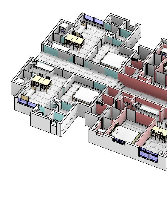
LODHA QUALITY HOUSING, MUMBAI
The next phase saw MHADA enter a special deal with Lodha group. Lodha would directly sell the units, and a certain percentage of the profit would be forwarded to MHADA. To accomodate for that, the project had been upscaled from affordable housing to quality housing, where the floor space was increased to more than 30 sqm.
The project still had a tight budget, and for the forst time, it was launched in a BIM platform, Revit. From the client’ss side, another project management BIM software, nPulse, was implemented.
The aim for this project on the architect’s side was to evolve to LOD 300 to LOD 350. The main barrier against achieving LOD 350 is the rarity of BIM-capable MEP or structural consultants. The next phase will aim to bridge that gap.
In this phase, links, quantities, schedules etc were made use of. Every family was custom-made for the project, with their own information and parameters.
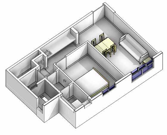
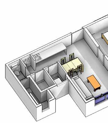
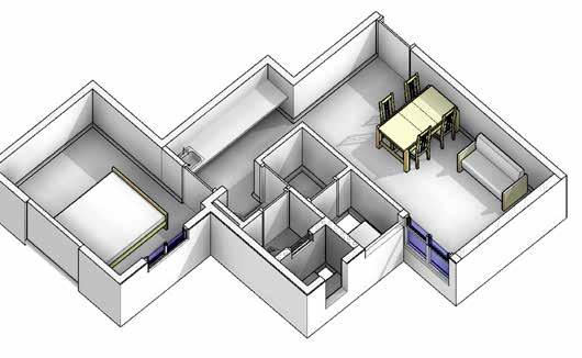
There were four kinds of units in this particular project, which were used in permutation and combination. Special care was taken for making each unit well-lit and ventilated.
12
BIM IMPLEMENTATION
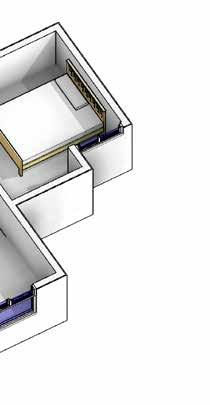
Unit C
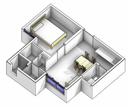
13
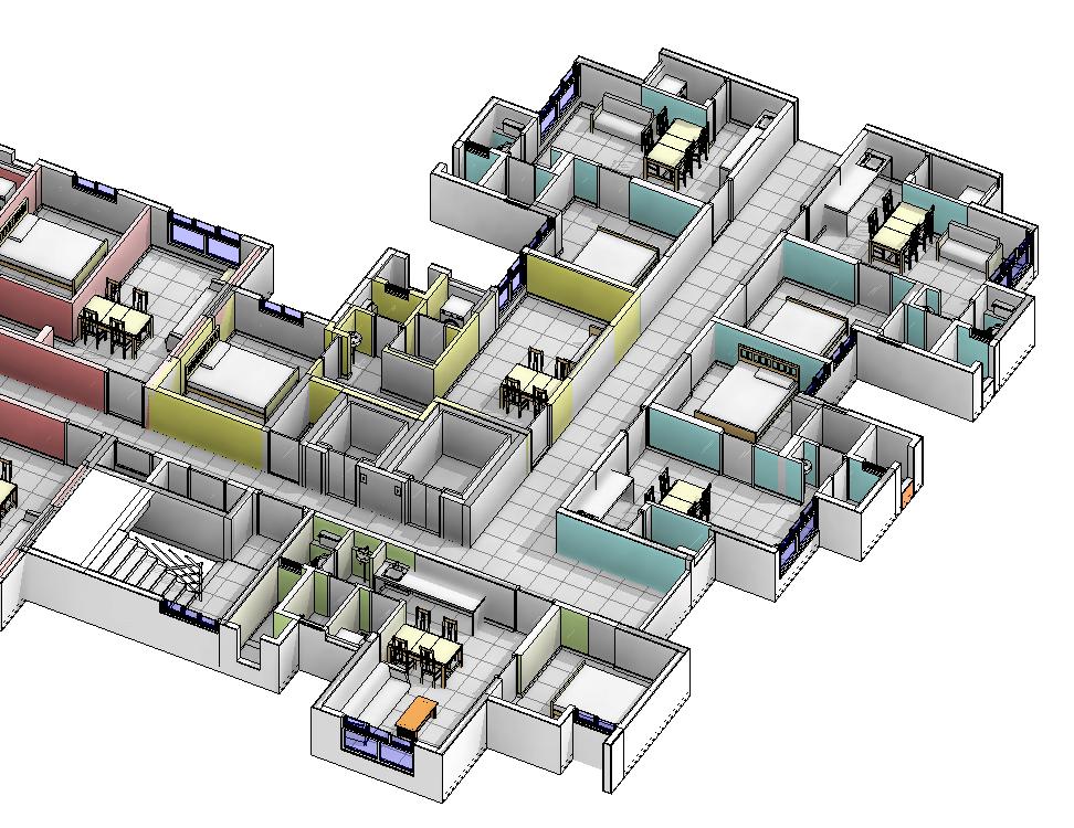
Assembled Floorplan
D
A
Unit
Unit
B
Unit
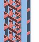
BIM COORDINATION & PRODUCTION
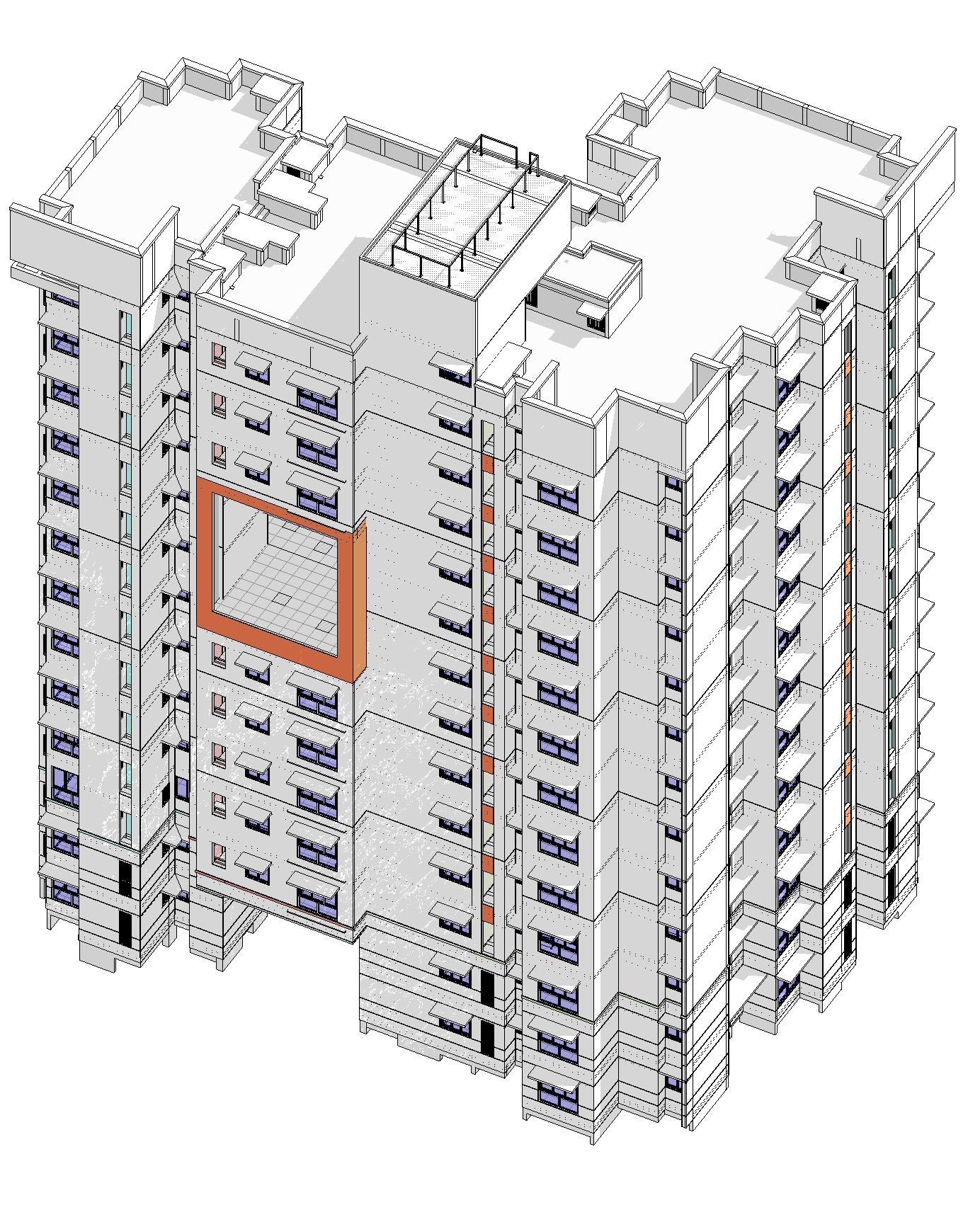
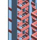

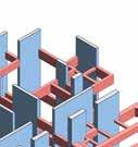
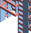


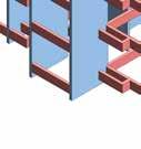

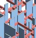
The structure model was modeled separately from the architecture model, based on the structure consultant’s CAD drawings. Both are combined to visually coordinate them and avoid any discrepencies.
From the architect’s side, the project is fully done in Revit, and all schedules, material take-offs etc are extracted from Revit.


1 2 4 6 7 8 10 12 13 14 16 17 18 19 20 21 22 23 24 25 26 27 28 29 30 31 32 33 34 35 36 37 38 39 40 41 42 43 44 45 46 47 48 49 50 51 52 53 54 55 56 57 58 15b Feature wall AA AB BB ALL DIMENSIONS ARE IN MM UNLESS OTHERWISE SPECIFIED DRAWINGS TO BE READ IN CONJUNCTION WITH RESPECTIVE STRUCTURAL & SERVICES DRAWING. DO NOT MEASURE FROM THE DRAWING; FOLLOW WRITTEN DIMENSIONS. FOR ALL TOILETS, KITCHENS AND STAIRCASES; PLEASE READ THIS DRAWING IN CONJUNCTION WITH THE RELEVANT TOILET, KITCHEN AND STAIRCASE DETAILS. ALL CHAJJAS ARE 750MM WIDE UNLESS OTHERWISE SPECIFIED. ALL LANDSCAPE LEVELS TO BE AS PER LANDSCAPE DRAWINGS. SINKING OF STRUCTURAL SLAB IN TOILETS AND KITCHEN AREAS TO BE AS PER STRUCTURAL DWG. ALL STEPS AND RAMPS SHOWN AT THE GROUND FLOOR LEVEL ARE INDICATIVE. PLEASE FOLLOW LANDSCAPE DRAWING FOR STEPS AND RAMPS AT THE GROUND FLOOR LEVEL. THIS DRAWING SHOULD BE READ IN CONJUNCTION WITH THE DOOR WINDOW SCHEDULE. THE PLINTH LEVEL FOR THE BUILDING W.R.T. THE SITE LEVELS SHOULD BE AS PER THE PLINTH LEVEL DRAWING/ LANDSCAPE DRAWING. BOTTOM OF ALL CHAJJAS TO BE ALIGNED WITH BOTTOM OF BEAM. SSL: STRUCTURAL SLAB LEVEL FFL: FINISHED FLOOR LEVEL; B.O.S BOTTOM OF SLAB; FT : FLOOR TRAP ALL SECTIONS/ DETAILS PERTAINING TO THIS DRAWING BELONG TO THE DRAWING SERIES : A-B2 '. FOR PARAPET DETAILS PLEASE REFER THE PARAPET DRAWINGS. REFER MEP DRAWINGS FOR LOCATION/ MANHOLE SIZES/ KHURRA/ RAINWATER DRAINS/ SLEEVES IN BEAMS/ CUT -OUTS IN FLOOR SLABS. TREAD WIDTH OF STEPS = 250MM, UNLESS OTHERWISE SPECIFIED LEGEND: PT-09 ASIAN PAINTS 8013 COPPER MOON BROWN PT-10ASIAN PAINTS L102 MILKY WAY WHITE PT-11ASIAN PAINTS 6142 STEEL DARK GREY PT-12ASIAN PAINTS 6126 NICKEL GREYLIGHT GREY NOTES DO NOT SCALE FROM THIS DRAWING. ALL DIMENSIONS SHOULD BE CHECKED ON SITE. BUILDING DESIGN PARTNERSHIP SHALL HAVE NO RESPONSIBILITY FOR ANY USE MADE OF THIS DOCUMENT OTHER THAN FOR THAT WHICH IT WAS PREPARED AND ISSUED. ANY DRAWING ERRORS OR DIVERGENCES SHOULD BE BROUGHT TO THE ATTENTION OF BUILDING DESIGN PARTNERSHIP AT THE ADDRESS SHOWN BELOW. 1 : 150 TOWER KEYPLAN-ROADSIDE Architecture Model Structure Model x 2750 x 1500 2150 x 4720 2750 x 1070 600 x 1550 1050 x 950 1350 x 1270 150 2810 x 4720 2750 x 1500 2150 x 1550 1050 x 1270 50 x 950 1350 x 1070 600 C641 C639 C640 C638 C637 C636 C659 C658 C657 C655 C656 C654 53 35 W 05 W 6A W 05 W 6A 04 05 Cha ja Abov e Cha ja Abov e er dwg no A-B2-A-TL-02 or o et b ock Refer dwg no A-B2-A-KT-02 for k tchen Re er dwg no A-B2-A-KT-01 or k tchen Ci l Ci l EDGE OF EXPANSION JOINT AS/DETA L SEVENTH FLOOR PLAN (SSL +20400 SSL) 1800 W DE CORRIDOR ROOM L VING D NING K TCHENETTE BATH SHAFT WC WASH UT LITY OOM K TCHENETTE L VING D NING UT LITY BATH SHAFT WC WASH D2 D1 D3 ED1 D3 ED1A D3A D2A D1A D3A + 20400 Para pet wa w h han d a a s de ai Para pet wa w h han d a a s de ai Gr l as/ De a i s Gr l as/ De ails 6 0 0 2 7 5 0 600 7 5 0 3 0 1 0 0 1150 1100 9 5 0 1050 1080 1 5 5 0 2750 7 5 0 3 2 0 1 0 0 600 9 5 0 1150 6 0 0 2 7 5 0 2750 1150 1 8 5 0 1400 1000 4 2 0 600 250 250 1350 50 1400 1 8 5 0 4 2 0 1000 600 250 2150 2150 80 170 80 170 1 5 0 0 7 5 0 T Y P ) 1100 1 0 7 0 970 250 9 3 0 1 0 7 0 250 1700 1700 970 1350 590 6 8 0 2 5 0 6 0 0 6 0 0 4 5 0 1 5 0 0 1 7 0 0 1 7 0 0 250 4 5 0 5 5 0 1150 4 7 2 0 4 7 2 0 920 VD01 ALL DIMENS ONS ARE N MM UNLESS OTHERW SE SPEC F ED DRAW NGS TO BE READ N CONJUNCT ON WITH RESPECT VE STRUCTURAL & SERV CES DRAW NG DO NOT MEASURE FROM THE DRAWING FOLLOW WRITTEN D MENS ONS FOR ALL TOILETS KITCHENS AND STAIRCASES; PLEASE READ TH S DRAWING N CONJUNCT ON W TH THE RELEVANT TO LET K TCHEN AND STA RCASE DETA LS ALL CHAJJAS ARE 750MM WIDE UNLESS OTHERW SE SPECIF ED ALL LANDSCAPE LEVELS TO BE AS PER LANDSCAPE DRAWINGS SINKING OF STRUCTURAL SLAB IN TOILETS AND KITCHEN AREAS TO BE AS PER STRUCTURAL DWG ALL STEPS AND RAMPS SHOWN AT THE GROUND FLOOR LEVEL ARE ND CAT VE PLEASE FOLLOW LANDSCAPE DRAW NG FOR STEPS AND RAMPS AT THE GROUND FLOOR LEVEL TH S DRAW NG SHOULD BE READ IN CONJUNCT ON W TH THE DOOR W NDOW SCHEDULE THE PL NTH LEVEL FOR THE BU LDING W R T THE SITE LEVELS SHOULD BE AS PER THE PL NTH LEVEL DRAWING LANDSCAPE DRAWING BOTTOM OF ALL CHAJJAS TO BE AL GNED WITH BOTTOM OF BEAM SSL: STRUCTURAL SLAB LEVEL FFL F N SHED FLOOR LEVEL B O S BOTTOM OF SLAB FT FLOOR TRAP ALL SECT ONS DETA LS PERTAIN NG TO THIS DRAW NG BELONG TO THE DRAW NG SERIES : A-B2 FOR PARAPET DETAILS PLEASE REFER THE PARAPET DRAWINGS REFER MEP DRAW NGS FOR LOCAT ON/ MANHOLE S ZES KHURRA/ RA NWATER DRAINS SLEEVES N BEAMS/ CUT - OUTS N FLOOR SLABS TREAD WIDTH OF STEPS 250MM UNLESS OTHERW SE SPECIF ED No es o door w ndow schedu e: A l d mens ons are n mm and are are unfin shed d mens ons Fo W02 sta rcase w ndow c eve sha be taken from m d- and ng SS eve C eve o be measu ed rom S ruc u a S ab Leve (SSL of apar ment un ess o herw se spec ed B O B Bo tom of Beam B O S Bo tom o S ab The door sw ng shou d be as representa on n th s d aw ng Fo hardwa e o nery and p acemen re e de a ed doo w ndow schedu e draw ng : A-B2-XXX-DR-SER ES The d mes ons o DWXX are sub ec to change as f na dec s on Precas L n e as deta GRAPHICAL NOTES: I CHAJJA (Fo ow be ow isted cha ja s zes unless otherw se spec f ed n the d aw ng) Cha a eng h = a Cha ja w d h = b = 750 (un ess o herw s e s peci ied) F g 1a Cha ja wi h ree edges Fig 2 : Cha a w th wa on wo s des b a 100 100 a w ndow eng h + 200 a b a d s ance be ween the s de wa s F g 1b Cha ja wi h ree edges b a a = c + 200 100 c 100 F g 4 : Cha a w th wa on one s de only a = w ndow eng h + 150 a b I BLOCKWORK BELOW KITCHEN SINK : I TO LET SHAFTS : 600 1 0 0 C eve 1075 mm f om apar ment SSL C C l leve n o et sha ts (open ng towards the court road s de) o be ma nta ned @1075 mm from apartmen SSL B ockwork be ow k chen s nk LEGEND: 100MM BLOCKWORK 150MM BLOCKWORK 200MM BLOCKWORK RCC CONSTRUCTION BLOCKWORK BELOW K TCHEN S NK STEPS IN BLOCKWORK APARTMENT NUMBER 150MM SOLID CONCRETE BLOCKWORK CUT OUT CUT OUT ABOVE NTERNAL DRAIN OFF POINT AS MEP DWG EXHAUST FAN xx -60MM SSL (c oss refer str dwg ) 150MM LEDGE-WALL N BLOCKWORK -250MM SSL (c oss refer str dwg ) +390MM SSL (c oss refer str dwg ) +200MM SSL (c oss refer str dwg ) +150MM SSL (c oss refer str dwg ) SLEEVE N BEAM AS MEP DWG 150 -150MM SSL (c oss refer str dwg ) Window Schedule Type Wid h (Structura Opening) He ght S l He ght (From SSL) Lintel Height (Structura opening from SSL) Descr ption LV01 600 1900 350 2250 Openable Louvered Window n Shaft LV1A 600 1900 350 2250 Fixed Louvered Window in Shaft LV02 600 600 470 1070 Terrace Shaft Louver SW 850 1300 450 1750 Smoke Window at L ft Mumty VD01 600 1900 350 2250 Cu out n front of to let shaft W01 1150 1250 1000 2250 Bedroom W02 1340 1900 350 2250 L v ng Room W03 1050 1750 500 2250 Entrance Lobby W04 1500 1250 1000 2250 Sta rcase/ Corridor W05 1900 1900 350 2250 L v ng Room W06 600 950 1300 2250 Bath W6A 600 1150 1100 2250 To let Door Schedule Door Type Width (Structura Open ng) Lintel Height (Structura opening from SSL) Si l He ght (From SSL) Area D1/ D1A 900 2250 0 Bedroom D2/ D2A 800 2250 0 Uti ty Ba cony D3/ D3A 750 2250 0 To let and Bath Area D4/ D4A 800 2250 0 Bath Door In Ut l ty Ba cony D5/ D5A 800 2250 0 Uti ty Ba cony from Bath Area ED1/ ED1A 1000 2250 0 Apartment Entrance ED2/ ED2A 1200 2250 0 Sta rcase ED3/ ED3A 1000 2250 600 F H C ED4/ ED4A 1000 2250 600 Electrica Shaft ED6/ ED6A 1200 2500 400 Sta rcase Mumty ED7/ ED7A 1200 2250 0 Entrance Lobby ED8/ ED8A 750 2250 600 Meter Room ED9/ ED9A 1200 2400 300 Pump Room ED10/ ED10A 1000 2250 0 Refuge Area / Meter Room EDXX/ EDXXA 1050 2250 0 Tower Entrance LD1/ LD1A 900 2250 0 Lift Door as/Vendor LD2/ LD2A 800 2250 0 Lift Door as/Vendor

15 W06 W06 W06 W06 W06 W06 W06 W06 W06 W06 W06 W06 120mm High 35mm thick extrusion in reinforced plaster Plastered and painted 1350mm High parapet wall & coping as/detail shaft LV01 LV1A VD01 VD01 VD01 VD01 VD01 VD01 VD01 VD01 VD01 Plastered and painted (PT-09) W05 W05 W05 W05 W05 W05 W05 W05 W05 W05 W05 W05 EDX1 D2 D2 D2 D2 D2 D2 D2 D2 D2 D2 D2 W07 W07 W07 W07 W07 W07 W07 W07 W07 W07 W07 120mm High 35mm thick plaster W01 W01 W01 W01 W01 W01 W01 W01 W01 Plastered and painted (PT-11) 3000mm High feature wall & coping as/detail W05 W05 W05 W05 W05 W05 W05 W05 W05 W05 ALIGN ALIGN ALIGN ALIGN ALIGN ALIGN ALIGN A Plastered and painted (PT-12) W06 W06 W06 W06 W06 W06 W06 W06 W06 W06 W06 W06 D2 D2 D2 D2 D2 D2 D2 D2 D2 W04 W04 W04 W04 W04 W04 W04 W04 W04 W04 W04 W04 Groove in Plaster Groove in Plaster Groove in Plaster Groove in Plaster Groove in Plaster Grooves in Plaster Railing as/details Groove in Plaster Overhead Water Tank Cutout in front of toilet shaft LV01 LV1A VD01 VD01 VD01 VD01 VD01 VD01 VD01 VD01 VD01 VD01 VD01 Plastered and painted (PT-09) 1350mm High parapet wall & coping as/detail W05 W01 W05 W01 W05 W01 W05 W01 W01 W05 W01 W05 Railing as/details Plastered and painted (PT-12) Plastered and painted (PT-09) Plastered and painted (PT-10) 120mm High 35mm thick plaster 1800mm High parapet wall & coping as/detail shaft LV01 LV1A VD01 VD01 VD01 VD01 VD01 VD01 VD01 VD01 VD01 VD01 W01 W01 W01 W01 W01 W01 W01 W01 W01 W01 W01 W01 1350mm High parapet wall & coping as/detail W06 W06 W06 W06 W06 W06 W06 W06 W06 W06 W06 Plastered and painted (PT-12) ALIGN Cutout in front of toilet shaft Plastered and painted (PT-11) LV01 LV1A VD01 VD01 VD01 VD01 VD01 VD01 VD01 VD01 VD01 VD01 ALIGN ALIGN ALIGN ALIGN ALIGN ALIGN ALIGN 1350mm High parapet wall & coping as/detail W05 W05 W05 W05 W05 W05 W05 W05 W05 W05 W05 W05 3000mm High feature wall & coping as/detail Plastered and painted (PT-11) 1350mm High parapet wall & coping as/detail +39750 SSL T.O.MUMTY +450 SSL +450_00 +3300 SSL +450_01 +6150 SSL +450_02 +9000 SSL +450_03 +11850 SSL +450_04 +14700 SSL +450_05 +17550 SSL +450_06 +20400 SSL +450_07 +23250 SSL +450_08 +26100 SSL +450_09 +28950 SSL +450_10 +31800 SSL +450_11 +34650 SSL +450_12 +450_13 OHT_TOP OF SLAB +40050 SSL T.O.FEATURE WALL D2 D2 D2 D2 D2 D2 D2 D2 D2 D2 TOS (Water tank) to be matched to building A (OHT Level) and details as/MEP dwgs CLIENT STRUCTURAL CONSULATANTS MEP CONSULATANTS INFRASTRUCTURE CONSULTANTS MASTER PLANNING LANDSCAPE CONSULTANTS M/s Palava Dwellers Pvt. Ltd. PBB Planner /Landscape Architect Tel 079 6923054 AECOM INDIA Pvt.Ltd. 9th Floor, Infinity Tower C DLF Cyber City.DLF Phase II Gurgaon 122002 Haryana, 8 9 10 11 12 13 14 15 16 17 18 19 20 21 22 23 24 25 26 27 28 29 30 31 32 33 34 35 36 15a 15b Typical Plan Unfolded Elevations UP UP 2750 4720 1050 1600 600 1070 1350 950 3050 2750 600 1070 1050 1600 2750 4720 1150 1270 600 1070 2750 3050 950 1350 1070 600 4720 2750 1500 2150 1600 1050 1500 2150 1270 1150 1070 600 2750 3050 x 5480 3000 x 1500 3330 1500 1100 1550 1050 x 850 2020 x 850 1250 810 1910 2150 1500 2150 1500 DN 1 2 3 4 5 6 7 8 9 10 12 13 14 16 20 19 18 17 A B D E F G H J K L N P Q R M S U W Y C T V X 15 M1 11 GROUND FLOOR PLAN (SSL ±00) GROUND FLOOR PLAN (SSL ±00) 1800 WIDE CORRIDOR 01 02 05 Chajja Above Chajja Above Chajja Above Chajja Above Chajja Above Chajja Above Chajja Above Chajja Above Chajja Above Chajja Above GROUND FLOOR PLAN (SSL +450) 1800 WIDE CORRIDOR Chajja Above D1A D1A D3A D3A D2A D3A ED1A D3A W01 W05 W6A W01 W01 W05 W6A W01 W05 W06 W01 W06 W05 W04 ED10A D2A D1A D3 D3 D2 ED1 D3 D1 ED2 D2 D3A D2A ED5 LD1 LD2 2750 3050 5480 1530 950 750 1800 2620 1880 600 1250 550 550 750 1190 1530 780 350 300770 2380 2100 2650 2020 1250 2000 (EIGHT EQUAL DIVISIONS) 1700 510 350 780 1250 1250 500 750 750 1690 1100 1440 10050 1600 1550 1850 470 2750 600 1150 970 1600 600 320 100 750 1034 1270 1150 520 910 880 930 1500 600 1800 2580 1280 500 600 3030 3000 250600250 LIVING/DINING KITCHENETTE BEDROOM BATH SHAFT KITCHENETTE KITCHENETTE LIVING/DINING BEDROOM LIVING/DINING SHAFT BEDROOM SHAFT WASH KITCHENETTE UTILITY LANDING ELECTRICAL SHAFT 30 1410 1030 1500 100 ED7A ED7A 3650 EDGE OF EXPANSION SLAB EXTENT ABOVE JOINT AS/STR. DETAIL ±00 SSL Refer dwg no. A-B2-A-KT-02 for kitchen Refer dwg no. A-B2-A-TL-02 for toilet block Refer dwg no. A-B2-A-TL-01 for toilet block Refer dwg no. A-B2-D-TL-01 for toilet block Refer dwg no. A-B2-A-KT-01 for kitchen Refer dwg no. A-B2-A-KT-02 for kitchen Refer dwg no. A-B2-D-KT-01 for kitchen Refer dwg no. A-B2-A-KT-01 for kitchen Refer dwg no. A-B2-A-KT-02 for kitchen Refer dwg no. A-B2-A-TL-02 for toilet block Refer dwg no. A-B2-A-TL-01 for toilet block Refer dwg no. A-B2-A-TL-03 for toilet block REFER STAIRCASE DETAIL A-B2-T07-ST01-01 100 100 LV01 LV01 LV01 C324 C317 C316 C318 C340 C338 C336 C335 C357 C352 C351 C350 C349 C346C C331 C332 C329 C348 C346B C346A C347 C328 C321 C323 C320 C319 C345 C327C C327B C327E C344 C342 C341B C303 C305 C307 C310 C309 C304 C306 C312 C313 C311 C314 150 150 150 600 1090 1300 3235 1105 195 1050 970 950 750 METER ROOM 1500 ED8A FTP CUT-OUT DOUBLE HEIGHT FTP CUT-OUT 17080 450 80 180 850 600 1070 4720 1700 450 300 300 790 1970 250 1700 1200 AS/LANDSCAPE DETAILS DETAILS TREAD 250 WIDTH 1500 TREAD 250 Parapet wall with handrail as/detail Parapet wall with handrail Parapet wall with handrail as/detail Parapet wall with handrail 150 W05 Grille as/details Grille as/details Grille as/details Grille as/details Grille as/details Grille as/details 1270 OPENING OF LIFTS AS PER VENDOR SPECIFICATION 1500 1500 TREAD 250 RISER 150.0 EDX1 CUT-OUT ABOVE CUT-OUT ABOVE Chajja Above 600 A 1550 750 750 750 950 2650 3050 1050 600 50 970 1100 150 920 1000 590 250 600 250 2150 1400 2750 1700 750 1150 1350 1250 170 80 250 1150 2750 1600 1500 1700 930 1850 680250 1070 3050 1050 600 1100 150920 1000 590 1400 1700 1150 1350 170 80 1150 2750 1034 750 470 1250 1270 600 600 2150 970 1600 1500 300 250600250 450 30 3050 1050 1600 1500 3350 600 50 970 1100 150 920 2810 1000 590 250 600 250 750470 1400 1700 750 1150 1350 900 1250 170 80 250 1150 450107080 2810 50 1850 600 30 930 250600250 470730 2150 300 1100 150 2750 1600 1500 320100 750 950 1350 500 430 150920 1070 1270 520 3050 750 1700 590 920 250250 450 7400 1690 1970 1700 1700 750 450 750 750 2150 1800 FOR METER ROOM 100 100 4720 100 930 2750 1250 820 750350 4720 920 1440 R1 R1 R1 R1 1050 195 2780 2 PLACEMENT OF DOOR REVISED ELEC. SHAFT DOOR CENTRALISED DOOR TYPE REVISED BLOCK WORK ADDED IN FRONT OF COLUMN, REFER DETAIL A 630 150 1200 LV01 -150 SSL -150 SSL 15mm plaster on external side 15+15 mm plaster on external face of blockwork 27 M wide Road 27 wide Road Pocket B Pocket B KEY PLAN CLIENT STRUCTURAL CONSULATANTS MEP CONSULATANTS INFRASTRUCTURE CONSULTANTS MASTER PLANNING LANDSCAPE NORTH M/s Palava Dwellers Pvt. Ltd. GOKANI CONSULTANTS PVT. LTD. 101 Kent Heights, Vardhman Nagar, Narsingh Lane, Malad (W), Mumbai -400064 T +91-22 28625553 T/F +91-22 28076866 E-mail projects@goakanicosultants.com MEP CONSULTING ENGINEERS 305, Options Commercial centre, Dr. Avasare Marg, Near Milan Subway, Santacruz (W), Mumbai -400 054 Fax 022-2612 5726 PBB Planner /Landscape Architect email landscapeindia@usg.net AECOM INDIA Pvt.Ltd. 9th Floor, Infinity Tower C DLF Cyber City.DLF Phase Gurgaon 122002 Haryana, DETAIL
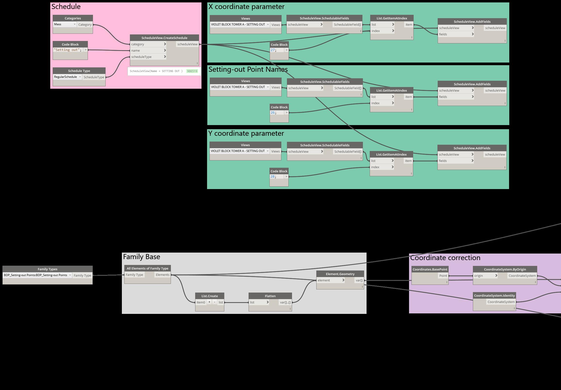
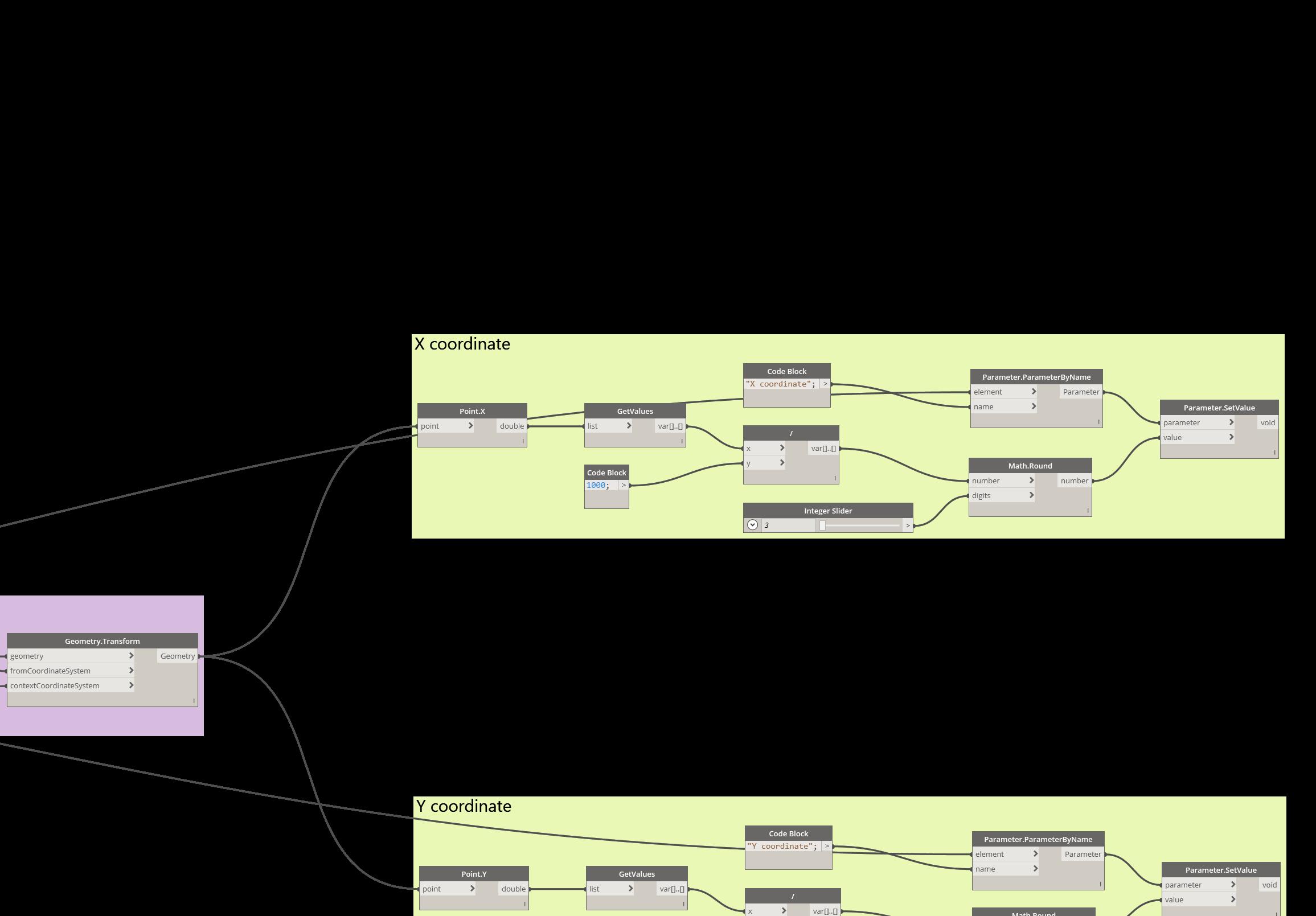
The client required exact GPS coordinates relative to the surveyor’s origin point in a tabular form. Unfortunately, that is not a feature in out-of-the box Revit.
To automate the process, a simple code was composed in Dynamo and after quality control, it generates a schedule for certain points in the model.
16
C-O3 N 1009 558 E 1827 532 4 0 3 0 1 4 0 3 4 5 0 1 4 5 0 1 3 0 600 600 600 600 1200 VIOLET BLOCK TOWER C - SETTING OUT POINT N (X co-ordinate) E (Y co-ordinate) C-01 1793 792 1009 558 C-02 1793 792 982 588 C-03 1827 532 1009 558 C-04 1827 532 982 588 NOTES DO NOT SCALE FROM TH S DRAW NG ALL DIMENS ONS SHOULD BE CHECKED ON S TE BUILDING DESIGN PARTNERSH P SHALL HAVE NO RESPONS B L TY FOR ANY USE MADE OF TH S DOCUMEN OTHER THAN FOR THAT W H CH IT W AS PREPARED AND SSUED ANY DRAW ING ERRORS OR DIVERGENCES SHOULD BE BROUGHT TO THE ATTENTION OF BUILDING DES GN PARTNERSHIP AT THE ADDRESS SHOW N BELOW DRAW ING TITLE BUILDING NUMBER(S) P8100081 2nd F oor Eros Corporate Tower Nehru Place SETTING-OUT PLAN DESIGN DEVELOPMENT
VISUAL PROGRAMMING
TO WER-C
17
C-O1 C-O3 N 1009 558 E 1827 532 2 6 7 0 1 4 5 0 3 4 5 1 5 0 2 8 0 4 9 0 0 4 0 3 0 1 4 5 3 5 0 1 4 0 1 3 0 600 600 600 430 600 600 600 600 600 600 600 600 0 1870 12850 1200 170 33740 0 9 5 1 0 5 0 2 6 7 0 1 3 6 1 4 7 3 5 0 1 4 5 1 2 0 0 1 4 5 1 2 5 0 1200 6 0 1450 3450 1200 1450 9150 0 0 0 0 2 4 5 200 1450 1200 6 0 0 0 0 9150 1200 1450 6 0 0 0 0 1190 N 1009 558 E 1793 792 V
DHAKA METRO LINE 5 (NORTH)
The
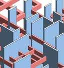
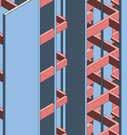
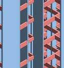
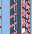
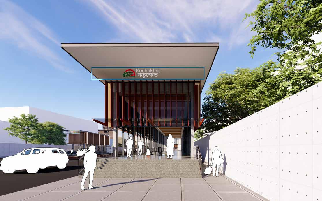
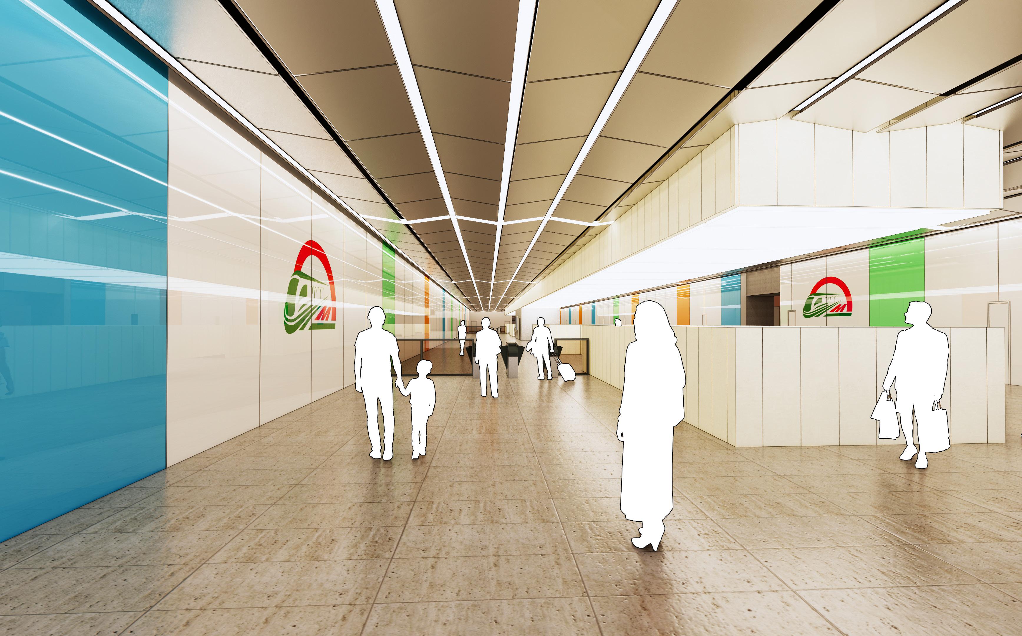
The concourse is the first proper area of the station which a passenger may see. Therefore, it was designed to be welcoming and straightforward. There are very few obstructions at eye level, so one end of the passenger-accessible part of the concourse can be seen from the other end.
The concourse ceiling is made of light aluminium baffles placed with a primary support grid above the fins to nestle lighting fixtures and services between the baffles.
The baffles have a smooth, yet non-uniform curve at the bottom edge. In a lengthy space like the concourse, the bottoms of the baffles create a three-dimensional wave, which is pleasant to look at and grand to stand under.
The walls of the concourse are designed with three materials: brown lacquered glass at the top with copper T-profile joints, a brass band in the middle, and then light, matte-finish stone at the bottom. Matte-finish grey stone is provided on the floor to make it brighter and spacious. This is the same in all standard stations in the line.
The concourse is a modern and stylish space to travel through, yet elegant enough to stop for a moment to admire.
Bangladesh has been climbing the global economic ladder quite fast in the recent few years. As a result, Bangladesh government has launched a few megaprojects with some support from other countries.
The Dhaka Metro project has been awarded to a leading Japanese company, who has hired BDP for the design of nine
underground stations. This project is one of the pioneering TOD projects in Bangladesh’s history. The international design collaboration has ensured that context of the region and comfort for the locals remains at the forefront of the design.
Dhaka Metro Line 6 has already seen test runs in May 2021, and the whole project is planned to conclude and open to public by 2028.
18 Dhaka Metro Line 5 North Basic Design Stage Report - ST10 Kochukhet July 2021 ST 10 - 20 Passenger Journey - Street Level
TRANSPORT-ORIENTED DESIGN
Metro Line 5 North July 2021 ST 10 - 13
Design Stage Report
Dhaka
Basic
- ST10 Kochukhet
Floor Level
General Arrangement Concourse
station
spaces that
passenger
the transition between street level and
form
activities
movement
are
concourse floor level extends the full length of the
box. It has a number of key
serve the
related activities to form
plat-
level. These
and
patterns
explained in later diagrams.
S1 -B S10- 8 Key BOH C Gene a C rcu a on Non Pa d Concourse O Pa d Concourse P an Room P b W C R R se s Serv ce S W f S a s T cket O ce 10- 5 S 0- 6 0- 7 S1 -0 S1 -09 0- 0 S 0- S1 -1 S1 -13 S10- 4 S 0- 5 S -1 S1 -1 S 0- 9 S1 -2 S1 -22 S 0- S1 -2 S1 -26 S10- 7 S 0- 8 S1 -29 0- 0 S1 -31 S1-S1 -F S 0-G 0- 3 S1 -A 0- 2 S 0- 3 S1 -3 S1 -35 10- 6 S 0-2 S1 -04 S1 -0 S 0- 0- 1 CL - Concourse Level - Proposed GA Plan 1 U D NG ES GN AR N RSH P SH L H V NO RE PON T OR NY US MA E F H NY DR W NG RRO S O D VE GEN E S OU D E ROU T TO H A T NT ON U D NG HE HE L H ND SA E Y ES GN S UE R G S E HE PRO E T HE L H ND A E Y S R G TE O NO CA E FR M T S DR W NG NOTES Roo Schedu e CL Numbe Name A ea 10-CL-P-25 ESCAPE CORR DOR 30 Roo Schedu e CL Number Name A ea P Roo S hedu e CL Numbe Name A ea O Roo Sch du e C Numbe Name A ea M Roo Schedu CL Numbe Name Area E UP UPS0 -1 Key BOH C rcu at on Genera C cu a on N P d C O f P an Room Pub c W Cs R t R sers Se v ce S f W S a rs T cke O ce S0 -05 S06- 6 S0 -07 S 6- 8 S0 -0 S0 -10 06- 1 S 6- 2 S -1 S0 -1 S06- 5 S 6- 6 S 6-1 S0 -19 S 6- 1 S0 -2 S06- 4 S 6- 5 S 6-2 S0 -2 S0 -28 S 6-2 S0 -3 S 6-3 S06S06-D S06-CS0 -G S0 -23 S06S0 -3 S06- 3 S 6- 4 S 6-3 S0 -3 06- 0 S0 -0 S 6- 3 6- 2 S0 -01 - --CL-M-0 -C -6-CL-E- 3 0 -C -C -0 6- L- -1 -C -M- 9 - -O-CL-O- 9 - -- -- -0 -C -C -0 - -0 -C -M- 7 - -- -- -- --C -CR0 - L- -0 - -- -- -- -- -0 -C -M6-CL-CR-C -C6-CL-E- 5 6-CL- R- 5 - --C -M- 6 6-CL-M-1 - -0 - L- -0 - -- -6-CL- R- 0 - -- -- -6- L-M-0 0 -C -M- 5 - -- - - 0 -C -C-1 0 -C -M- 9 - -- -- -- -6-CL-M-1 - -- -0 - L- -1 0 -C -E-0 0 -C -O- 0 - --C -O- 5 - -0 -C -O- 6 0 -C -O- 6-CL-CR- 1 6-C -- -- --C -CR-2 - -6- L- R- 7 -C -C6-CL-E0 -C -O- - - - -0 -C -C-0 6-CL-E- 2 - L-- - - - -6-CL-C- 5 6-CL-M-1 - - - - - - - -- -- -6- L-O-0 - -6-CL-C- 8 - -6-CL- - 6 10000 10000 10000 10000 10000 9000 6000 10000 10000 10000 10000 10000 10000 10000 10000 10000 10000 10000 10000 10000 10000 10000 10000 10000 10000 10000 10000 6000 6320 12680 10000 10000 10000 10000 10000 2 1 0 0 6 5 5 0 6 5 5 0 2 1 0 0 8 6 5 0 4 3 5 0 - -- -1 500 CL - Concourse Level - Proposed GA Plan TN RS P SH A E O R SPO S Y OR AN U E M DE OF TH S S OR V RGE C S HOU D BE BRO GH TO TH T EN ON OF BU LD NG S G S U S G R S S R S F RAW GS R N N M 6- L-M-1 P PEWOR R ER 6 6 M 6- L-M-1 F RE SU RES ON 1 6 M 6- L-M-1 P SH F 4 6 M 6- L-M-1 SMO E XT AC R ER 1 6 M 6- L-M-1 FAN OOMS 2 6 M 6- L-M-1 F RE F G T G R SER 1 6 M 6- L-M-1 ME H V NT R S R 7 6 O O 6- L- -0 F 7 6 O 6- L- -1 S A F WE F RE 1 6 O 6- L- - 2 E O 1 9 O 6- L- - 9 P OPER Y DEV LO MEN 4 6 O 6- L-O-0 C EANER 1 6 O 6- L-O-0 D TE T O ROOM 1 6 O 6- L-O-0 PO E ROOM 2 6 O 6- L-O-0 F RS A D ROOM 1 6 O 6- L-O-0 S A ON CONT OL ROOM 4 6 O 6- L-O-0 T CK T OFF CE 2 6 O 6- L-O-1 T CK T OFF CE STO E 1 6 O 6- L-O-1 P OPER Y DEV LO MEN 4 6 O 6- L-O-1 T CK T OFF CE 2 6 O 6- L-O-1 T CK T OFF CE STO E 1 6 O 6- L-O-1 F RS A D ROOM 1 6 O 6- L-O-1 C E NER CP 1 6 O 6- L-O-2 GA BAG 1 6 R N b N E 6-CL-E- 6 AFC ROOM 14 6 E 6-CL-E- 7 BN 38 6 E 6-CL-E- 8 R SE T C 1 6 E 6-CL-E- 0 RE F GHT NG R SER 1 6 E 6-CL-M-0 ACCE S AREA 5 6 E 6-CL-M-1 ACCE S AREA 5 6 E 6-CL-M-1 PRES UR A ON HA T 4 6 E 6-CL-M-2 ELE R ER 3 6 E 6-CL-O-0 STA ON MANAG R 24 6 M M 6-CL-M-0 STA ON VEN R SE 13 6 M 6-CL-M-0 PR S AF 4 6 M 6-CL-M-0 AN ROOMS 36 6 M 6-CL-M-0 PRES UR A ON HA T 4 6 M 6-CL-M-0 PR S AF 2 6 M 6-CL-M-0 AHU ROOM & CS ROOM-1 24 6 M 6-CL-M-0 SMO E X RAC R SER 8 6 M 6-CL-M-0 ME H V NT R ER 5 6 M 6-CL-M-0 RE SU RES ON 19 6 M 6-CL-M-1 AHU ROOM & CS ROOM-1 28 6 R T N b N A S -C -CR- AN R ROOM -C -CR- RE SUR ZA ON SH F -C -CR- M N ENA CE LOB Y 0 -C -CR- T ESC PE 4 -C -CR- T -C -CR- L C R SE -C -E- &M PS BA TE Y ROOM 9 -C -E- S R BC -C -E- L CT CA M N B ROOM 7 -C -E- OMMS 5 -C -E- L C R SE -C -E- L CT CA ANEL OOM 6 -C -E- U D G COMMS ROOOM 5 -C -E- E ECOM EQU PMEN ROOM 8 -C -E- L C R SE -C -E- E ECOM T ROOM 3 -C -E- PS ROOM 0 -C -E- L CT CA ANEL OOM 9 -C -E- L C R SE -C -E- L C R SE -C -E- L CT CA M N B ROOM 3 R N N CR 6-CL-CR- 2 GARBAG 1 6 CR 6-CL-CR- 3 MA NT NAN E OBBY 3 6 CR 6-CL-CR- 4 E CA E CORR DO 3 6 CR 6-CL-CR- 5 OBB 6 6 CR 6-CL-CR- 6 E CA E TA R 2 6 CR 6-CL-CR- 7 S RV CE CORR OR 2 6 CR 6-CL-CR- 8 S RV CE CORR OR 4 6 CR 6-CL-CR- 9 WC CORR DO 1 6 CR 6-CL-CR- 0 S RV CE CORR OR 2 6 CR 6-CL-CR- 1 E CA E TA R 3 6 CR 6-CL-CR- 2 OBB 7 6 CR 6-CL-CR- 3 MA NT NAN E OBBY 5 6 CR 6-CL-CR- 4 OBB 2 6 CR 6-CL-CR- 5 E CA E CORR DO 3 6 CR 6-CL-CR- 6 E CA E TA R 3 6 CR 6-CL-CR- 7 P B C WC 9 6 CR 6-CL-CR- 0 P B C WC 2 6 CR 6-CL-CR- 1 P B C WC 2 6 CR 6-CL-CR- 2 E CA E CORR DO 1 6 E E 6-CL-C-07 FT 6 6 E 6-CL-C-08 E E R ER 3 6 E 6-CL-C-08 E E R ER 9 6 R T N A S 0 -C -C- L FT 0 0 -C -C- EN RAN E CO E 3 0 0 -C -C- EN RAN E CO E 5 0 0 -C -C- EN RAN E CO E 5 0 0 -C -C- EN RAN E CO E 1 0 0 -C -C- UNP D CONCOU SE 3 0 0 -C -C- PA D CO COURSE 9 0 0 -C -C- SECUR Y ONE 0 0 -C -C- SECUR Y ONE 0 R R 0 -C -CR-0 ESCAPE S A R 0 R 0 -C -CR-0 LO BY 0 N S W E Entrance to Kochukhet Station Concourse Plan July 2021 Key BOH Circulat on General C rculation Non Paid Concourse Office Paid Concourse Plant Room Public W C s Retai Risers Service Staff W elfare Stairs T cket Off ce S10-31 S10-32 S10-33 S10-34 S10-35 S10-36 Key BOH Circulation General C rculation Non Paid Concourse Office P ant Room Publ c W Cs Reta l Risers Service Staff W elfare Stairs Ticket Office 3 S06-34 S06-35 S06-36 10000 10000 10000
The spaces within each floor level are illustrated and described on following plan drawings.
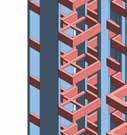
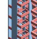
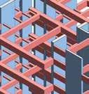
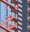
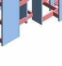
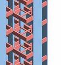
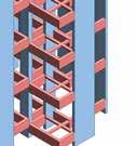
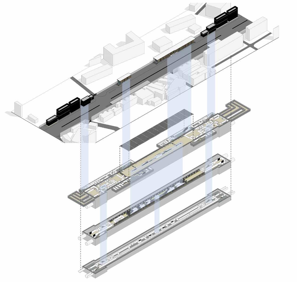
BLOWN-UP VIEW
A full set of General Arrangement drawings are also provided in Appendix A of the report.
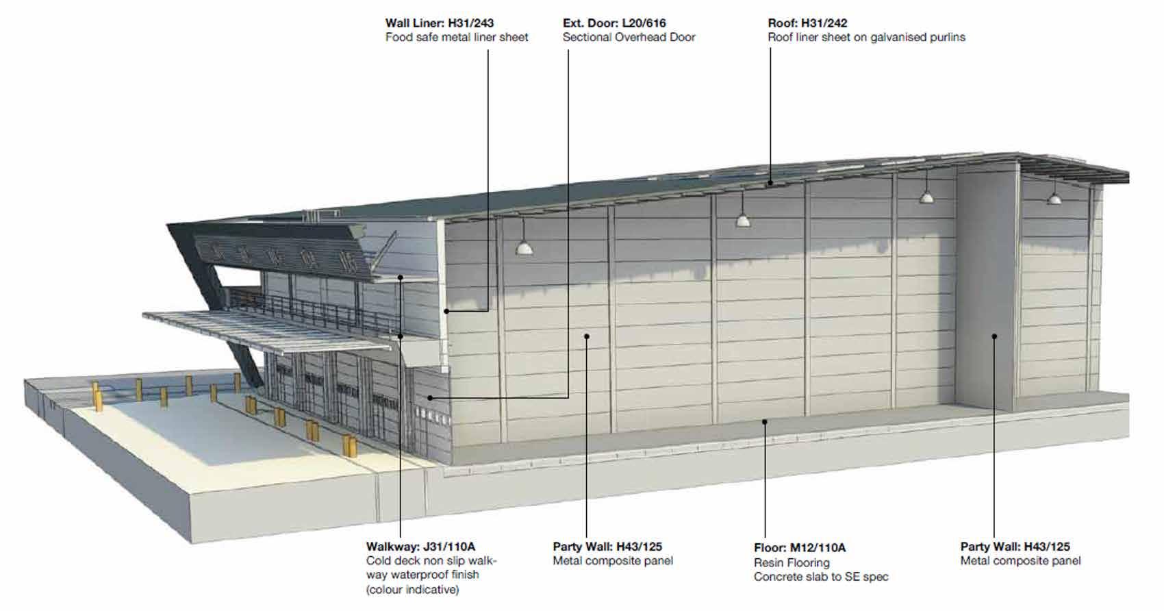
The building is made up of the following key architectural components and features;
Above Ground :
Below Ground:
Basic Design Stage Report - ST10 Kochukhet
All the above are illustrated and explained in further detail in proceeding diagrams, drawings and visualisations.
19
ST 10 - 10 1 5 4 9 8 8 8 8 8 8 2 2 3 6 7 7 1 ST 10 - 10 1 5 4 8 8 8
1. Entrance and Escape Cores.
2. Entrance Canopies.
3. Tunnel and Building Vent Cores
4. External Ancillary spaces.
5. Concourse Ceiling
6. Concourse Circulation Area.
7. Retail Units.
8. MEP Spaces.
9. Platform with Services Undercroft.
2 2 3 7 1
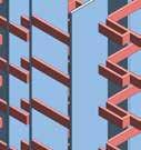
Passenger Journey - Concourse Level
20 CONCOURSE VIEW Dhaka Metro Line 5 North Basic Design Stage ST
21 Report - ST6 Dar-us-salam July 2021 ST 6 - 26
3TS HOSPITAL, BRIGHTON
buildings with modern facilities for the provision of 21st century healthcare.
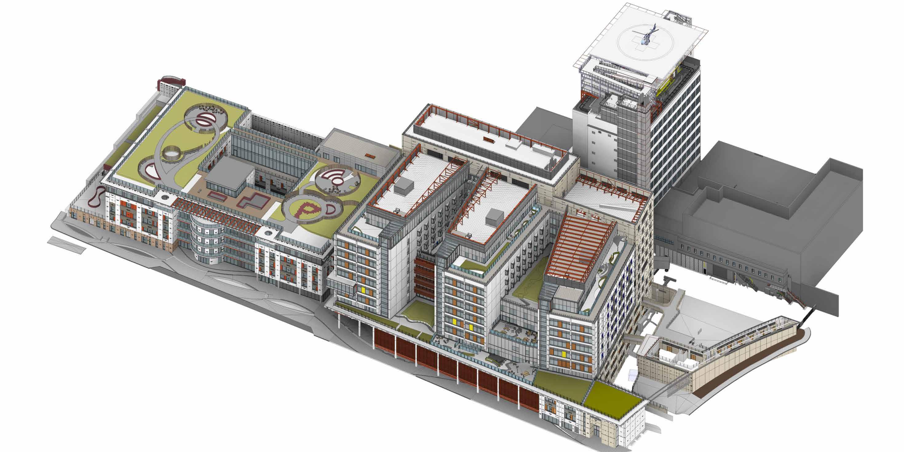
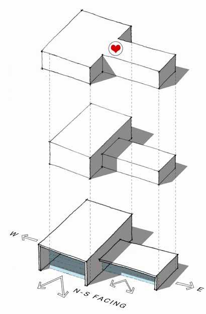
The project fits a large scale hospital sensitively into its historic context. The topography of the site is fully exploited with the mass of the building broken down into fingers, which contain the bulk of the ward accommodation and face south with views over the English Channel.
also led extensive negotiations with the local authority on the complex Section 106 Agreement and planning conditions.
The brief was to redevelop the Royal Sussex County Hospital on a very constrained site and replace 200 year old
BDP was involved in detailed negotiations with the local planning authority and English Heritage, in relation to design and heritage issues. BDP
Two new state-of-the-art hospital buildings will bring Elderly Care, General Medicine, HIV and Clinical Infection wards up to modern standards, and establish the hospital as the Major Trauma Centre for the region. The new build will include 361 beds, 65% of which will be in single en-suite rooms, a helipad and additional parking spaces underground.
22 HEALTHCARE
Axonometric view of all the phases, Kemp Tower at the back
23
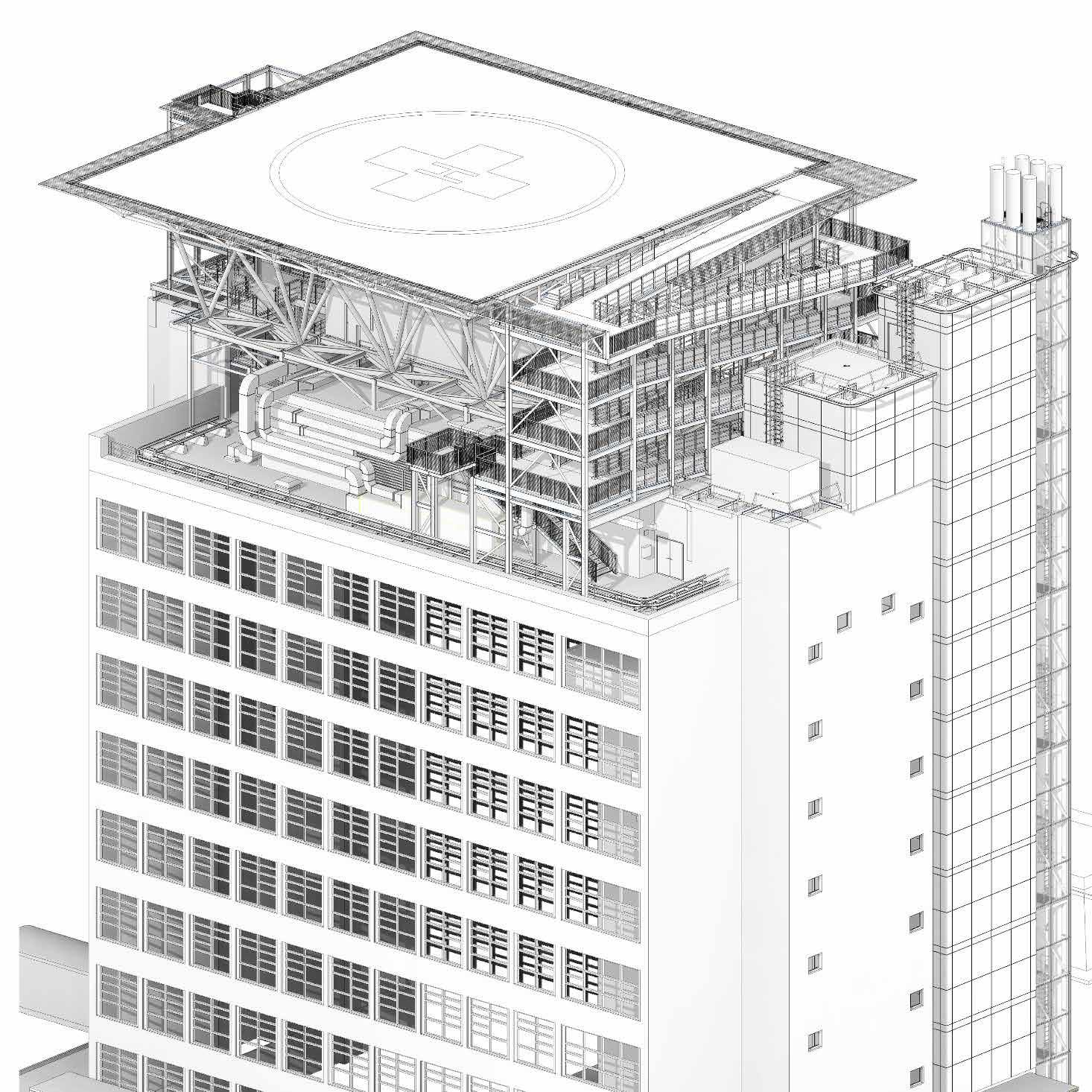
Helipad on top of the Kemp Tower
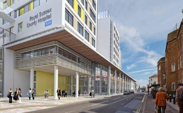
Front Entrance
EDUCATION
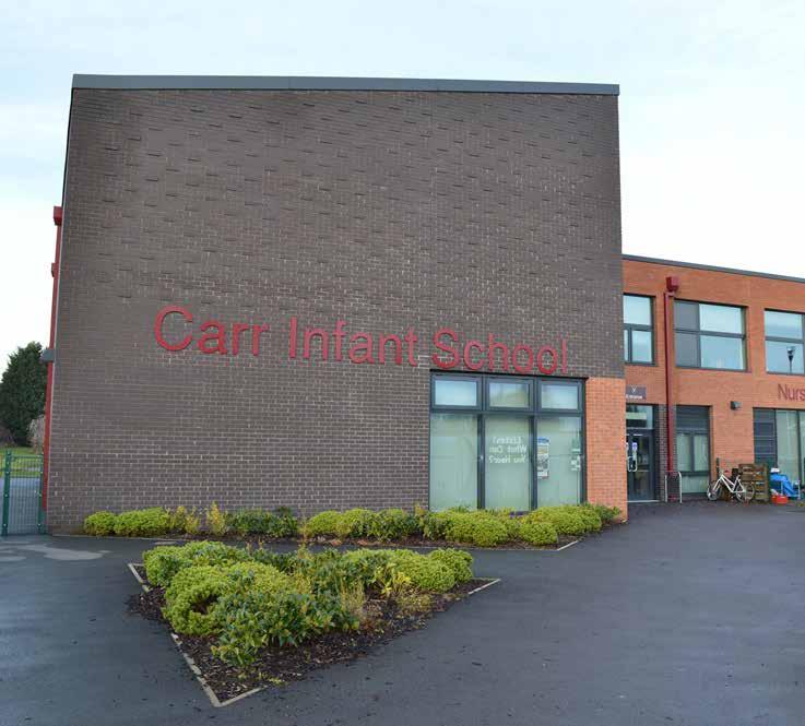
CARR INFANT SCHOOL, SHEFFIELD
RevisonDescription
-First Issue
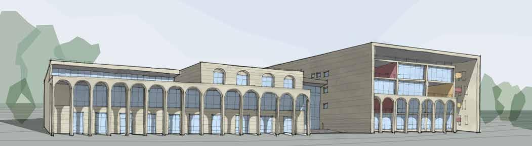
The Yorkshire Carr Infant School project is located in Acomb, York.
This school is a refurbishment and redesign of an older school, that suffered from a variety of issues, including dampness and a lack of proper natural light and ventilation. The new school building has successfully eliminated that.
The building is 2 storeys high and consists of two blocks: the main hall and the classroom block. It has been designed according to the latest and updated British specifications.
24
Image of the finished school
25
DrawnCheckedDate
ADSPPO30.10.14 UP UP 0 Ma n Ha Gene a O ce Interview Room L brary Resou ce Centre 8 Food Bay Pract ca Resou ces 7 SEN Therapy/M Room Hygiene Fac li es 8 Ce St k Ma n enance Equipment S ore 7 S R 5 Ac b Toi 12 m SEN Resource Base 3 Sick Bay 12 Chai S ore Table Sto e PE Store 47 Kit he 4 Ex ernal S o e 23 Plan Ent ance Recep on C eaners Store 20 Cir ulatio 2 Cir ulatio 9 Small Group Room A C D E C-L F 14 m LRC 3 m Class S orage Recept on 11 Circulation 1 2 24 Cir ulatio App iance S ore 8 3 4 5 6 7 C/L 11 Circulation Circulation 62 Reception C assroom 62 Reception C assroom 16 Heads Office Meet ng Roo C kro 13 Recept on Toi ets 3 Class S orage (Recept on Sen or Managemen Off ce 62 m Reception C assroom 2 m Class S orage (Recept on 6 m Recept on Toi ets C oakrooms Nursery Playroom 8 N rsery Toilets m C oakrooms 2 m Class S orage (Nurse y 14 m Nursery Group Room 3.4.1 14 10903 37150 89 0 169 527 181 0 719 169 8 89 0 B C oakrooms 2 Circulation 7 Circulation PSBP: Yorkshire Batch - Carr Infant Schoo @A2 Da ed Chec awn D o p Des n s Re e D ed c Ch awn D on p s D n s Rev 1 100 Ground Floor P an (L-00 BDP-03(20)AP100 F 14 10 3 PPO ADS ssue rs F14 10 7 PPO ADS 5 CEM o Changes Plan A 14 10 14 PPO ADS 6 CEM o Changes Plan B C Pl Ch ng for draft ITT b ADS PPO 17.10.14 D Plan Changes based on CEM-6 tracker PPO PPO 21.10.14 E Genera plan & e evat on amendments ADS PPO 24.10.14 -- -- -- -14 10 30 PPO ADS on ss subm TT or ssued & Updated F
PSBP: Yorkshire Batch - Carr Infant School@A3
BDP-03(20)A_CGI_102-
Plan of the school
View of the Carr Infant school
EDUCATION
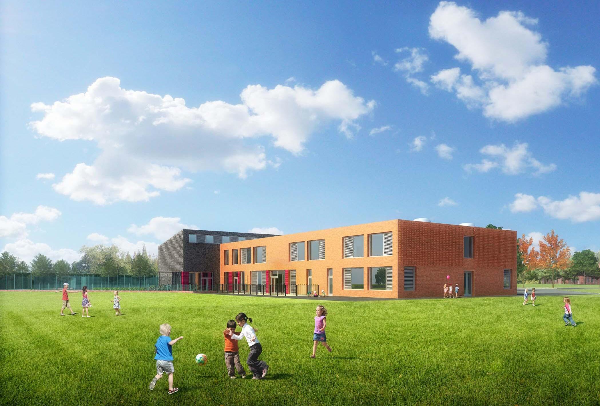
DON VALLEY ACADEMY, SHEFFIELD


Don Valley Academy is a school in Sheffield with a capacity for 1500 pupils.
The design consists of two separate new-build elements of Teaching Block and Sports Block. These are sited respectively to the north and south of a retained and refurbished single storey Sixth Form and Business Studies Centre, to
create a simple and legible new linear campus on the site.
The Teaching Block is a three storey building consisting of linear wings of teaching accommodation offset around a central triple-height atrium space. The communal spaces of Dining Hall, Library and Main Hall are clustered around this heart space and form the focus of school life.
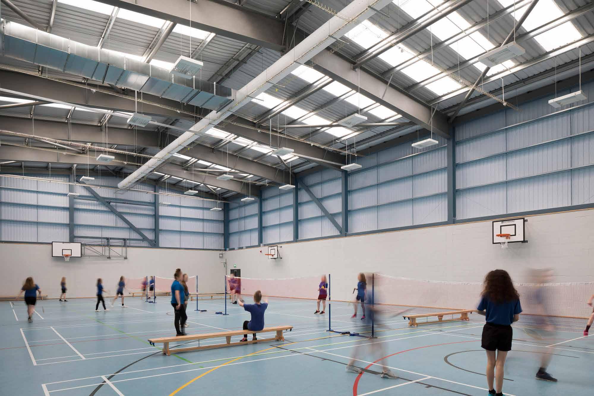
The Sports Block is a single storey building, open to out of hours community use and located in close proximity to the sports pitches at the south of the site.
26
Entrance to the school
View of the school
27
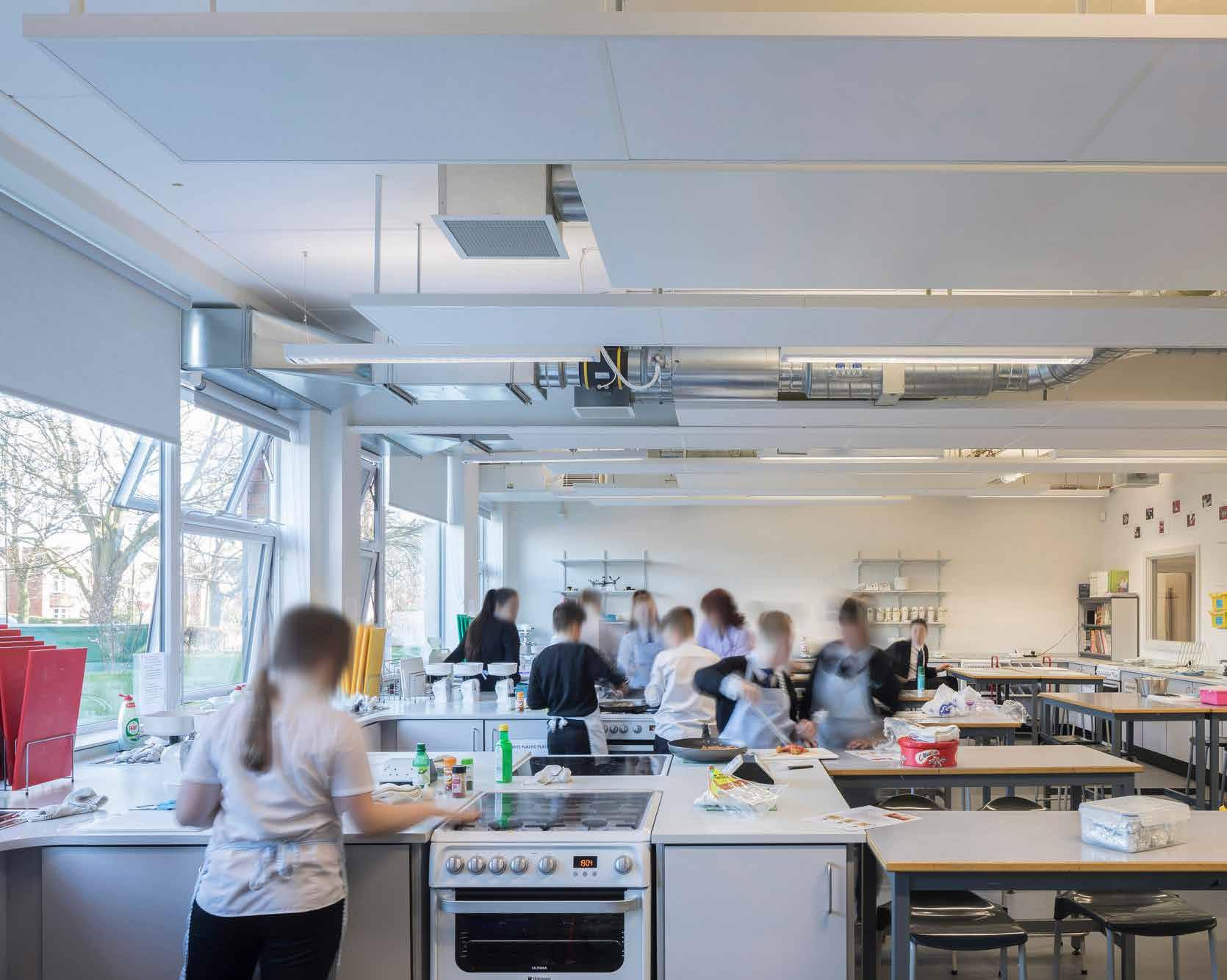
Home science class
The sports block
PUBLIC & RETAIL
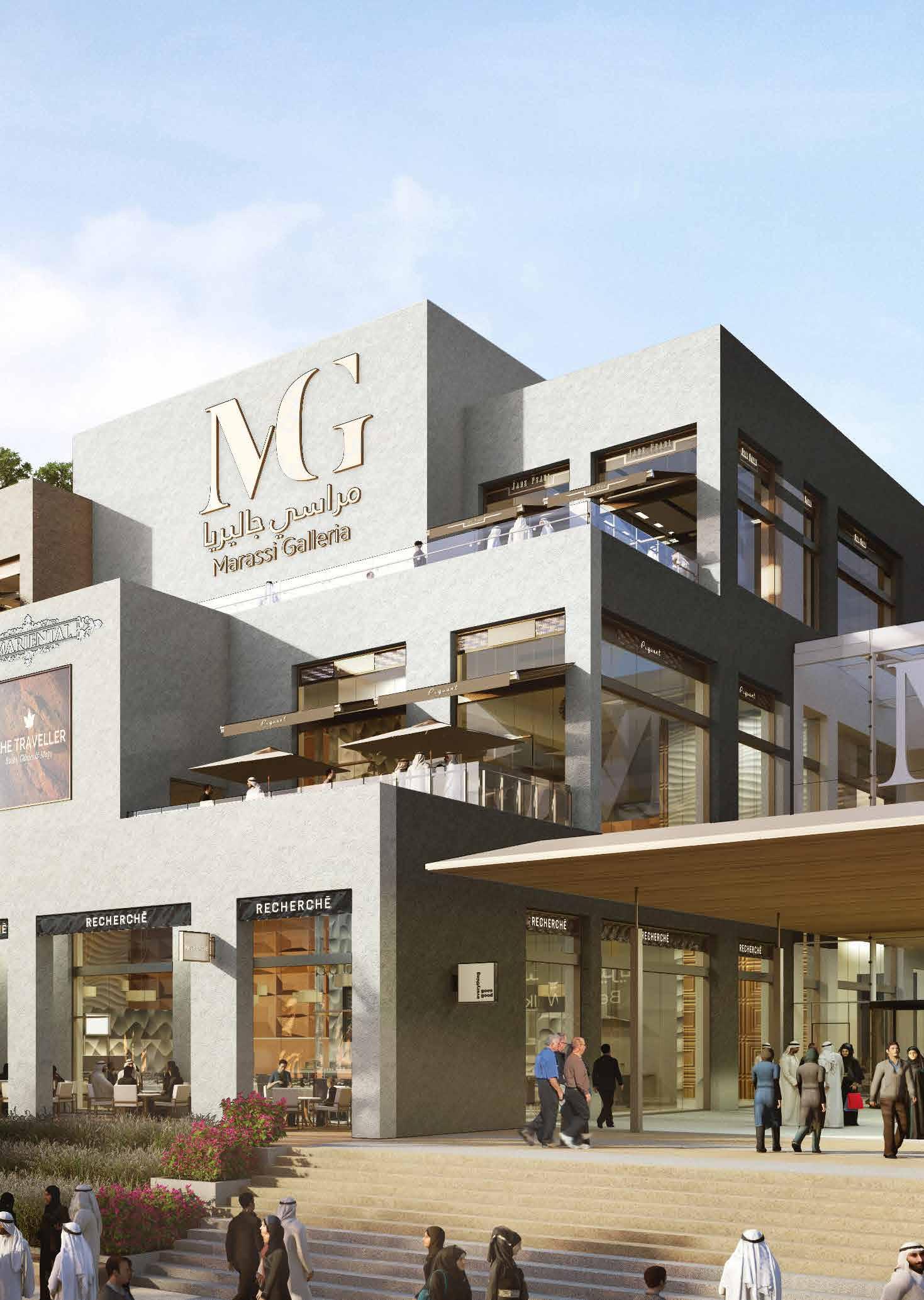
MARASSI GALLERIA MALL, BAHRAIN
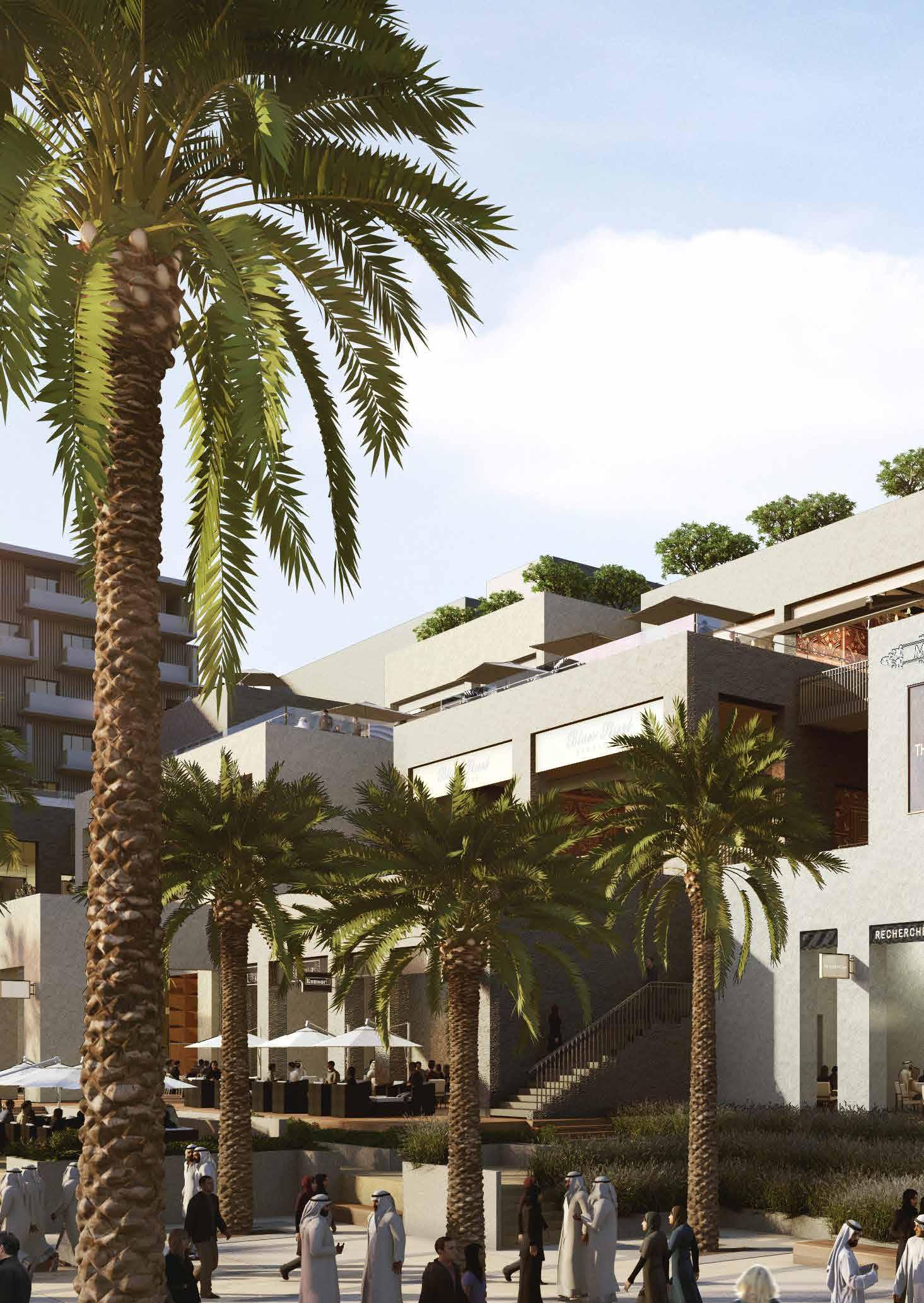
Marassi Galleria is a gigantic mall in the heart of the new equally colossal Marassi city in Bahrain, a project undertaken by the Emaar group, UAE.
Inspired by the fine grain of the traditional Al-Muharraq Old Town, and the aspiration to create a centre which engages deeply into its context and surrounding community, the design seeks to create a Town Centre, rather than a Retail Centre. This is achieved by exploiting the retail planning to create a series of individual buildings, rather than continuous retail façades.
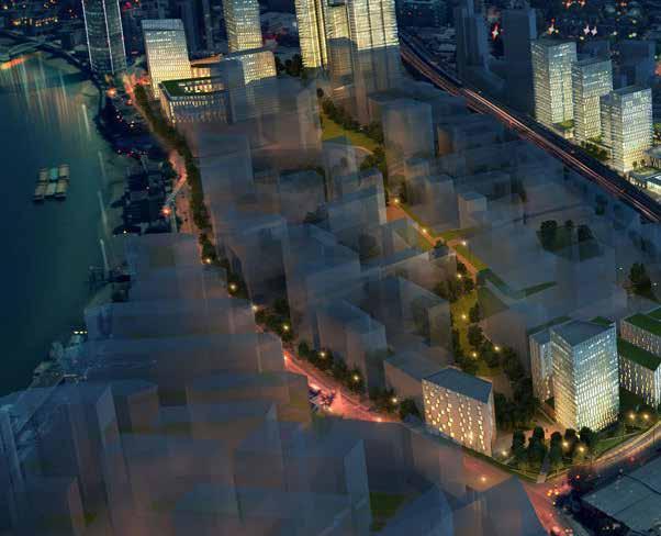
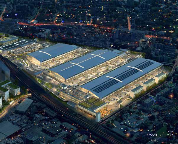
NEW COVENT GARDEN MARKET, LONDON
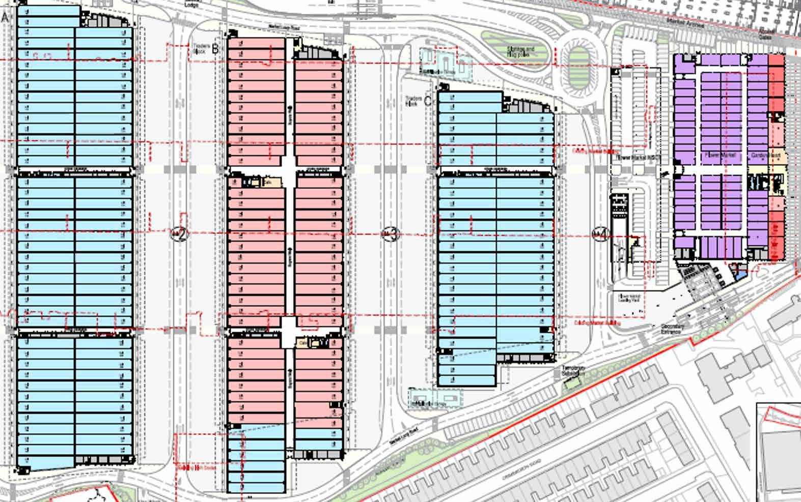
The masterplan for ‘The Garden’, a 23 hectare regeneration of New Covent Garden Wholesale Market, is the largest redevelopment scheme within the Nine Elms regeneration area on London’s South Bank. It will secure the future of New Covent Garden
Market, the UK’s largest fruit, vegetable and flower market, through the delivery of new 21st century facilities.
The market proposals will provide 47,000 sqm of modern facilities consolidated on one site for the 200 tenant businesses, which employ over 2,500 people. This will sit alongside a new food quarter as part of the new market, known as The Garden at New Covent Garden Market.
The design consolidates the market south of the Vauxhall railway viaduct, releasing 8 hectares of surplus land, which will be transformed into
a high quality residential-led mixed-use neighbourhood, comprising 3,000 new homes, office space and retail including shops, cafes and restaurants.
The entire scheme will be set alongside a new linear park stretching alongside the river Thames from Vauxhall to Battersea Power Station, and will also be home to the future American and Netherlands Embassies. The area will also benefit from the extension of the underground and the opening of two new tube stations, connecting people living and working in Nine Elms to wider areas in London and beyond.
30
RETAIL & STORAGE
31
Masterplan of the market
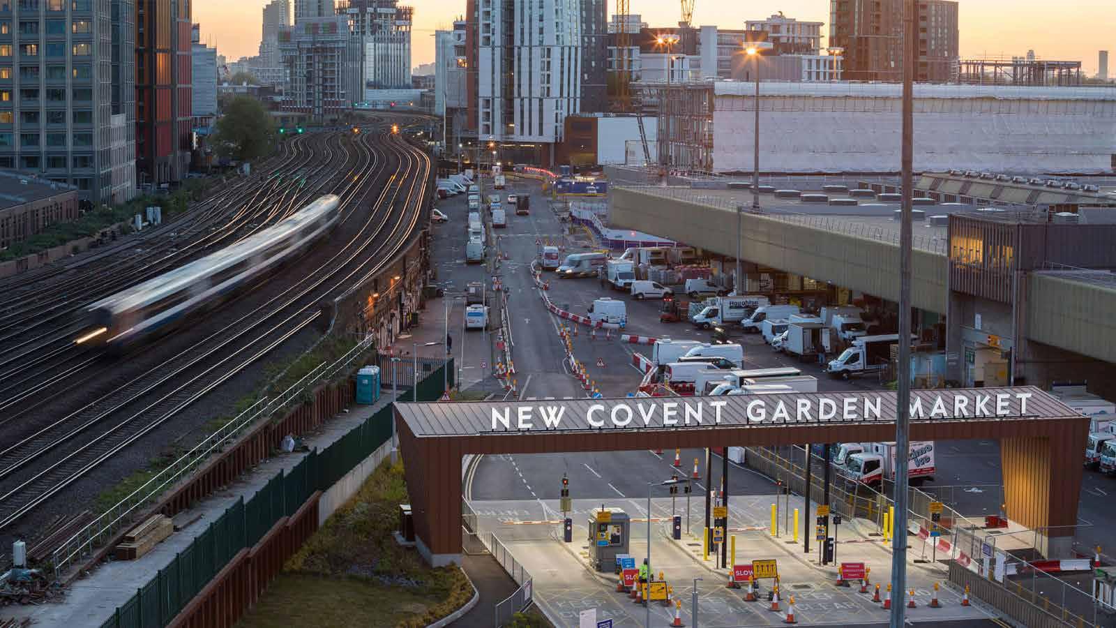
Aerial
view of the market
32
Entrance to the market
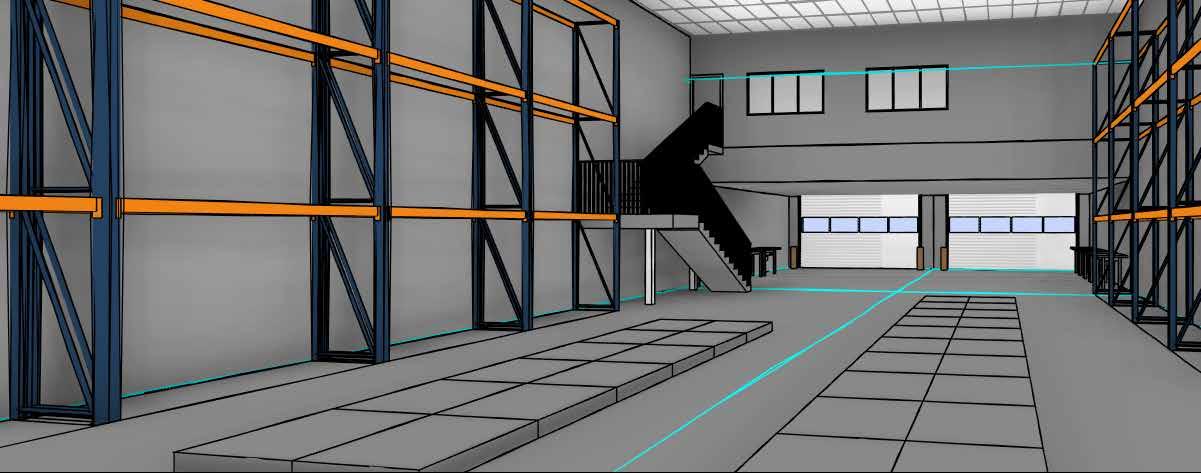
Interiors of one shop
Anatomy of the market
NIRLON KNOWLEDGE PARK, MUMBAI
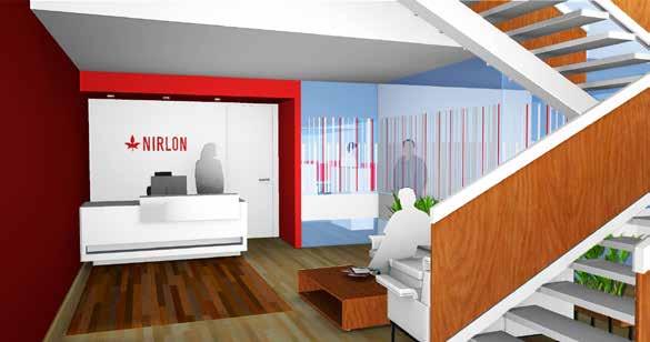
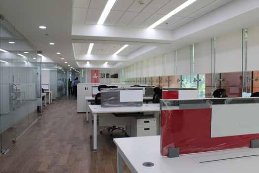
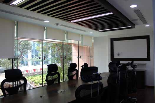
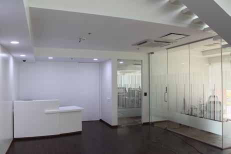
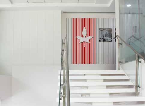
Nirlon Ltd, previously a manufacturer of synthetic fibres, has its head office at Goregaon, located in western Mumbai. Here, an interior project was started as a follow-up of a much larger project for Nirlon knowledge park in Mumbai, India.
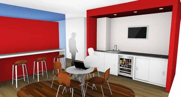
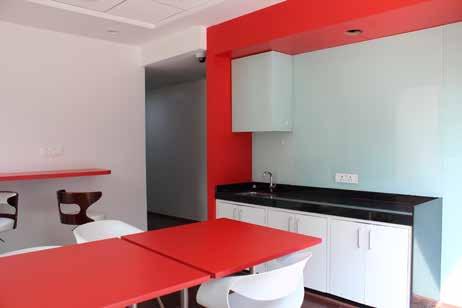
The project consisted of office spaces in two levels. The client had wanted the furniture and the decor to reflect the trademark Nirlon brand.
33 INTERIOR
DESIGN
Reception as visualized
Pantry as visualized
Reception as built
Pantry as built
Office space as built
Meeting room as built
Top of the staircase
NHSR TRAINING FACILITY, VADODARA

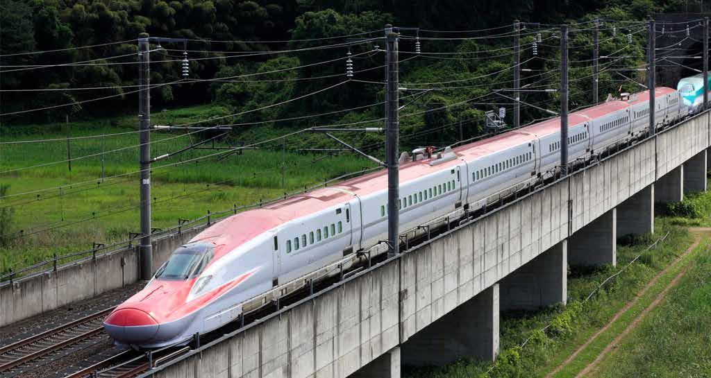
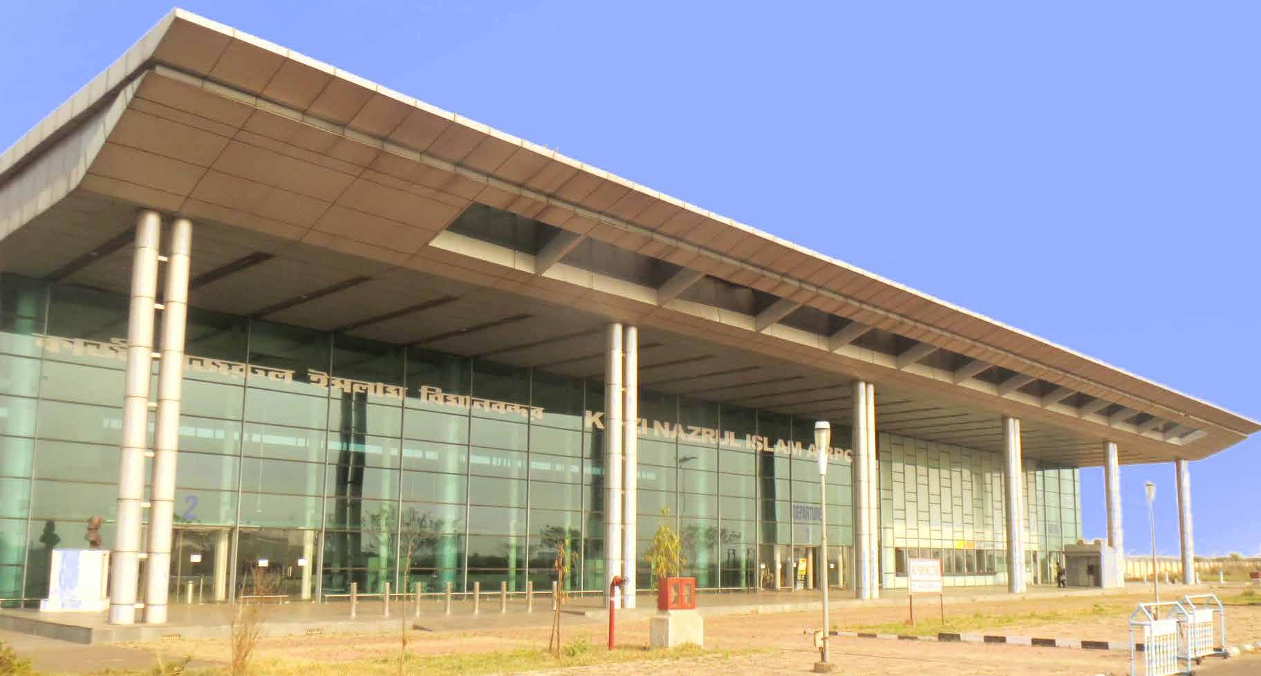
National High Speed Railway Corporation Limited is implementing the project of high speed train corridor between Ahmedabad and Mumbai. The total length of proposed High Speed Railway Corridor works out to be 508.17km.
The route of Mumbai Ahmedabad High Speed
Rail will be passing through two states, Maharashtra and Gujarat and one Union Territory, Dadra and Nagar Haveli, of the Union of India.
The proposed corridor lies in Western Railway zone. It shall start from Bandra Kurla Complex in Mumbai and will end near Sabarmati Railway Station in Ahmedabad.
The training center in Vadodara would be a key institute for training railway staff and engineers. It will have every kind of cutting-edge technology and simulations which are currently used in Japanese Shinkansen training institutes in Japan.
34 TRANSPORT-ORIENTED DESIGN
Early concepts
Early concept view
TECHNO-ECONOMIC VIABILITY STUDY SUJALAAM AEROCITY, ANDAL
Incorporated in 2007, Bengal Aerotropolis Projects Limited (BAPL) is a specialized infrastructure company engaged in identification and development of aerotropolis projects in India. It is now developing an aerotropolis (or Skycity) at Durgapur in West Bengal within the 1616-sq-km Asansol-Durgapur Planning
Area (ADPA).
BAPL has signed a joint venture development agreement with West Bengal Industrial Development Corporation Limited (WBIDC) for developing India’s first private Greenfield aerotropolis, comprising an airport, an industrial skyzone, a logistics skyhub, an information technology skypark and a township in the Asansol-Durgapur
region of Burdwan district in West Bengal, one of the most significant industrial zones in eastern India. The West Bengal Government under the leadership of the Honourable Chief Minister, takes an active interest in this marquee project of Bengal and through WBIDC has injected fresh equity funding for an increased stake in the company.
Proposal Option
35
BACHELOR THESIS
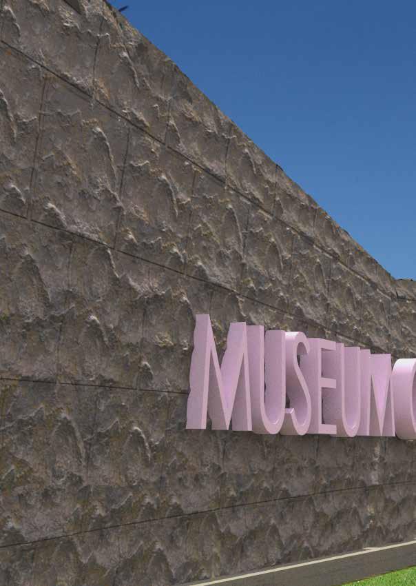
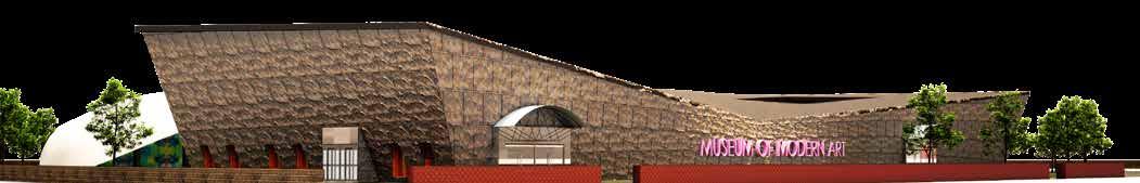
MUSEUM OF MODERN ART, KOLKATA
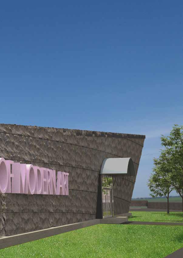
The Museum of Modern Art, Kolkata, not to be confused with the Kolkata Museum of Modern Art (KMoMA, by Herzog & De Meuron), was an effort towards redefining the concept of ‘art’ in the modern context.
Traditionally, art involved a physical medium like paint on canvas, or chiselled stone. But with the advent of modern technology, the limits of art has been broadened by the virtual world.
This museum aimed at marrying the old with the new, thereby blurring the horizon of art.
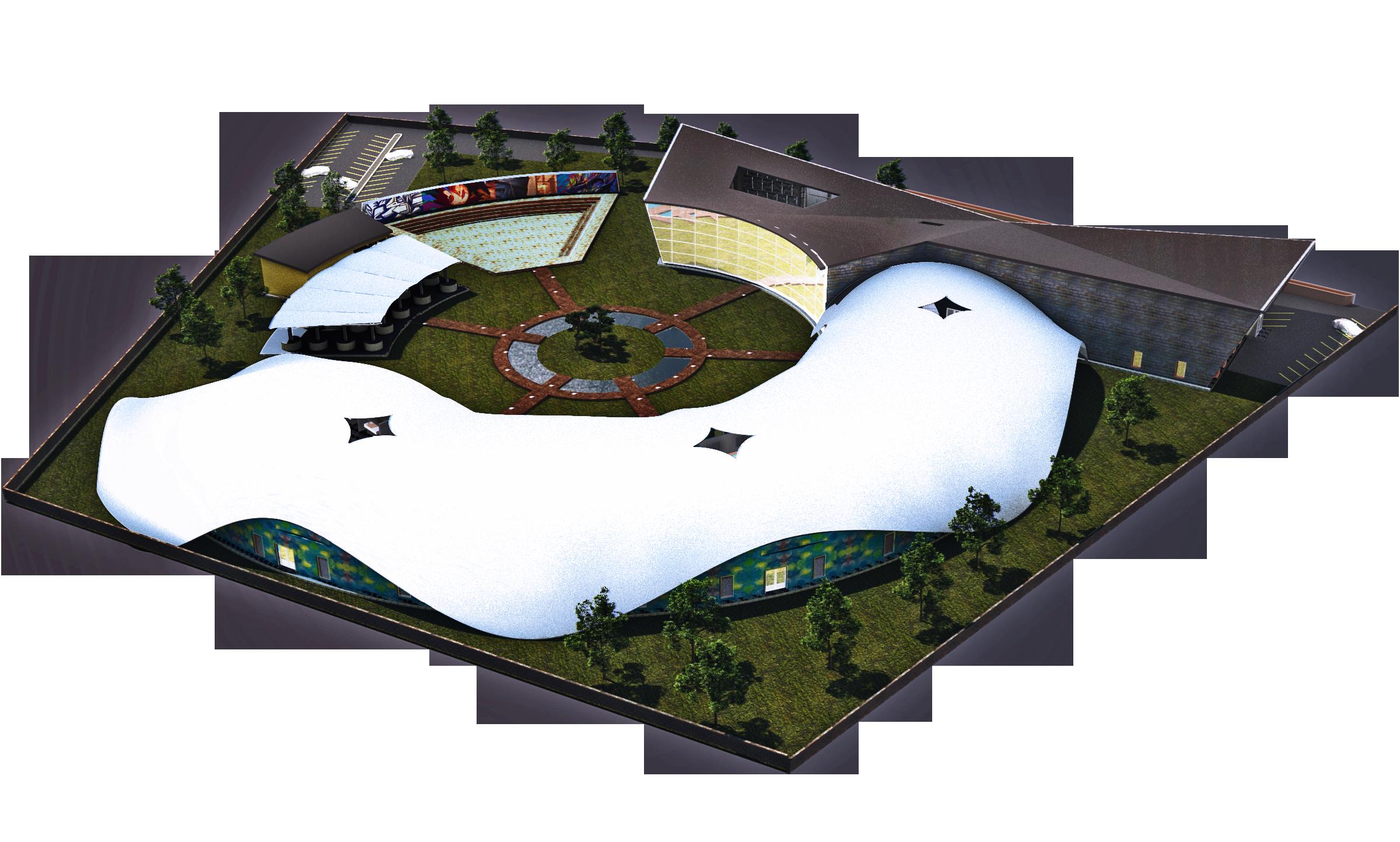
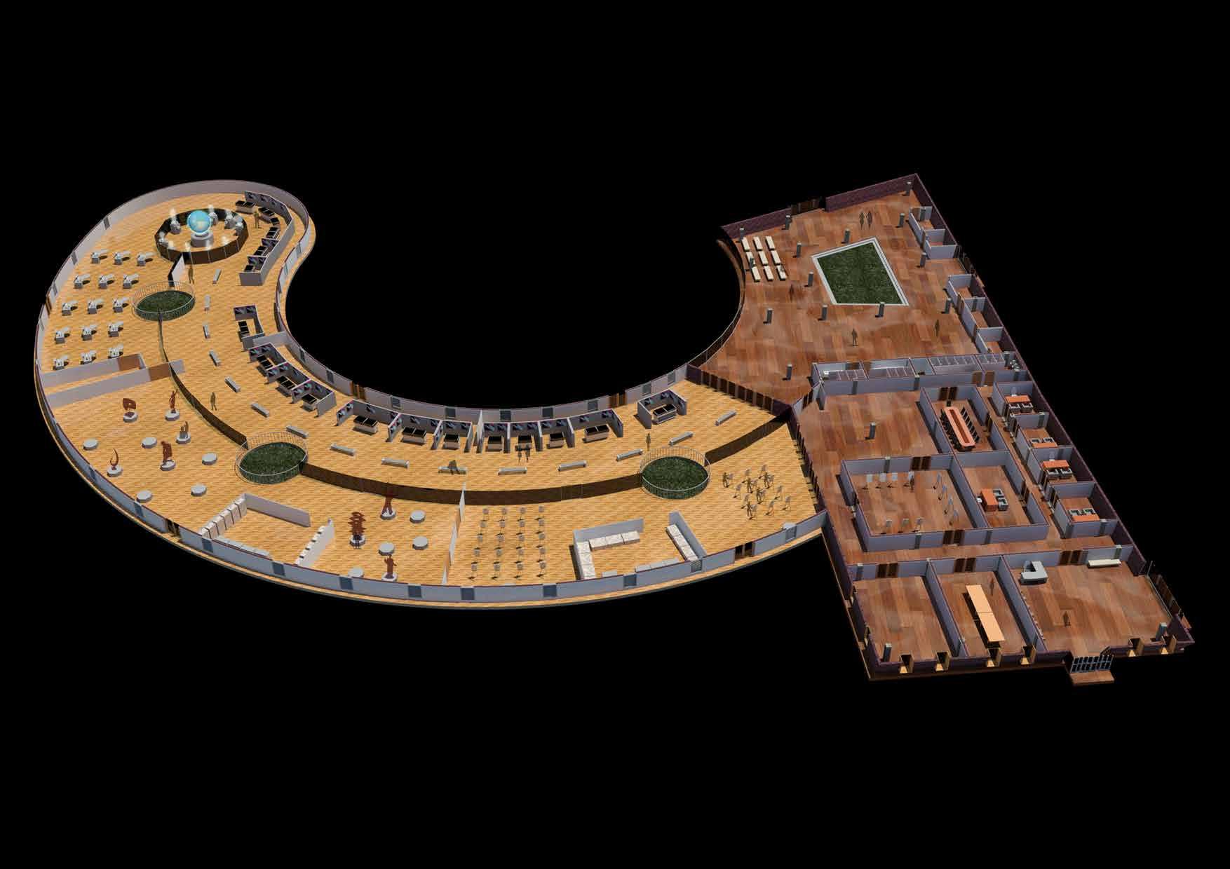
MUSEUM SPACES
Parking
Canteen
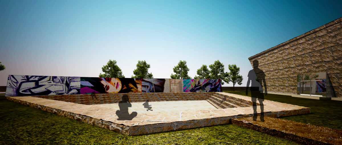
Exhibition wing
Open-air theatre
Entrance and administrative wing
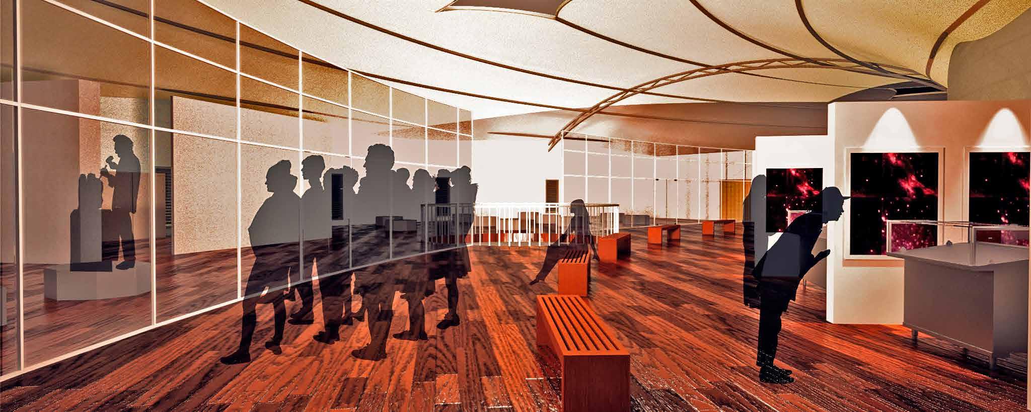
Projector screen
Hologram display
Digital exhibition
Entrance lobby
Contemporary display
Traditional gallery
Staff Parking PTFE Stretched roof
The site
Assistance
Main entrance (Visitor)
Cloak room, Lost & Found, First-aid Souvenir shop
Offices
Curator’s cabin
38
Staff entrance Staff room
Restoration room
Painting studio
Sculpture studio
Digital art studio
The museum spaces

The museum boasts to be a balanced space between a workplace, a learning space, and a place for relaxation.
The museum is purposefully left visually porous, so that visitors can not only admire the finished artwork, but also the very process that creates them.
One special room in the museum is the hologram room, where hologram projectors are installed for a 360o view of digital artwork.
39
VIEWS
The galleries and the studios
The open air theatre
The hologram room
The entrance building
ARTICLE THE SAMI PEOPLE


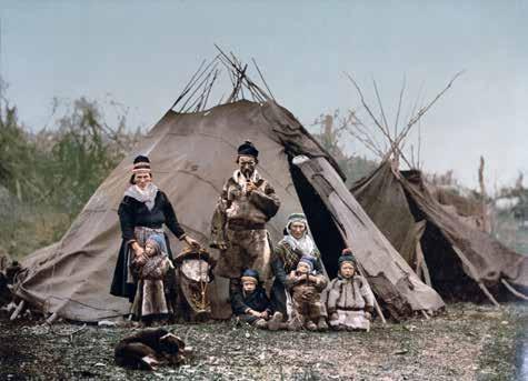

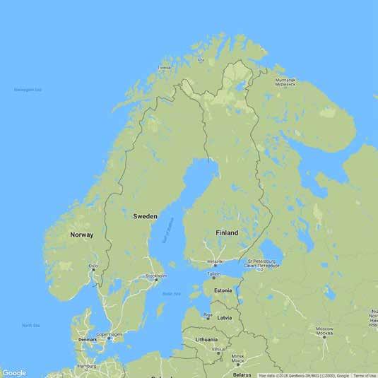
The Sami are an ethnic group living in the far north in four countries- Norway, Sweden, Finland and Russia. The Sami have been recognised by the United Nations as an indigenous people, giving them the right to preserve and develop their crafts, language, education, reindeer husbandry, traditions and identity.
The Sami were originally nomads, living in tents during the summer and more sturdy peat huts during the colder seasons. Today, the Sami live in modern housing and only use tents as very temporary accommodations during reindeer migrations if they don’t already own cottages in the mountains and forests. Most Sami live in the north, but there are Sami all over Sweden. Today, only ten percent of Swedish Sami earn a living from the reindeer industry, and many combine their family businesses with tourism, fishing, crafts and other trades.
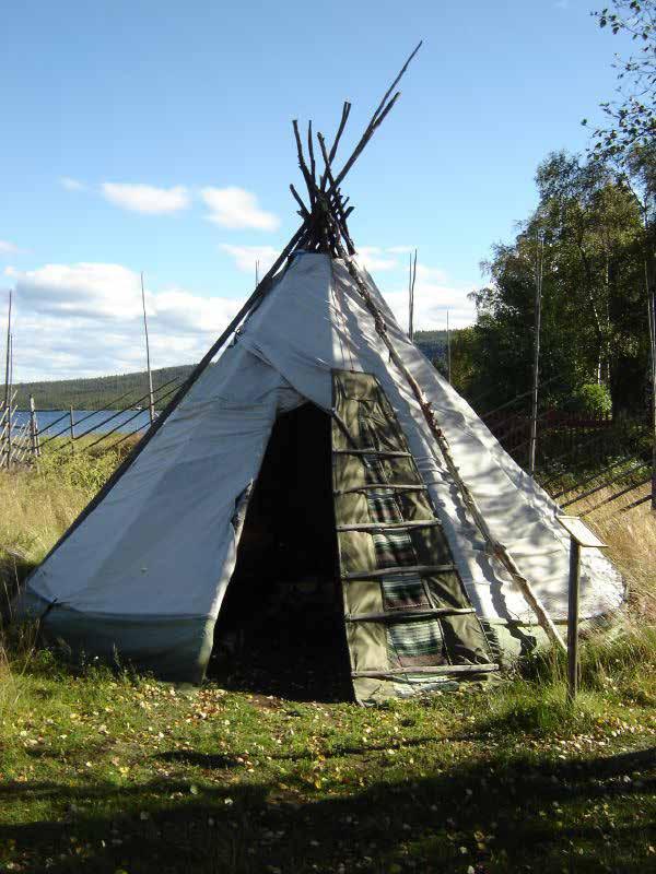
Traditionally, during summer, the Sami live in conical tents called lávvu (Northern Sami language) or kåta (Swedish). It has a design similar to a Native American tipi but is less vertical and more stable in high winds. It enables the indigenous cultures of the treeless plains of northern Scandinavia and the high arctic of Eurasia to follow their reindeer herds. The lávvu is perfect for their nomadic lifestyle.
Inside the living quarters of the lavvu, there is a fireplace in the middle used for heating and to keep mosquitoes away. The smoke escapes through the smoke hole in the top of the lavvu.
40
A lavvu under the Aurora
A Sami village
Sami people in front of lavvu
A Sami reindeer herder
“STUGA”, LYCKSELE, SWEDEN

Astuga (image in left), is a traditional Swedish cottage, usually with a single room, and built of timber. Nowadays, a stuga is more of a summer retreat to Swedish people.
The design for such a stuga was requested by the client for her mother, who describes herself as one with the “heart of a hermit”. She also emphasises that she is a fan of compact, miniature homes and rustic, traditional architecture.
The client’s mother currently lives in Vilhelmina, but wishes to shift near Lycksele, in close proximity to her existing family.
41
DESIGN
SITE SUNRISE05:30 SOLAR NOON 16:18 SUNSET 18:09 SUMMER SOLSTICE SITE SUNRISE 14:19 SOLAR NOON 16:14 SUNSET 18:09 WINTER SOLSTICE 21st DECEMBER
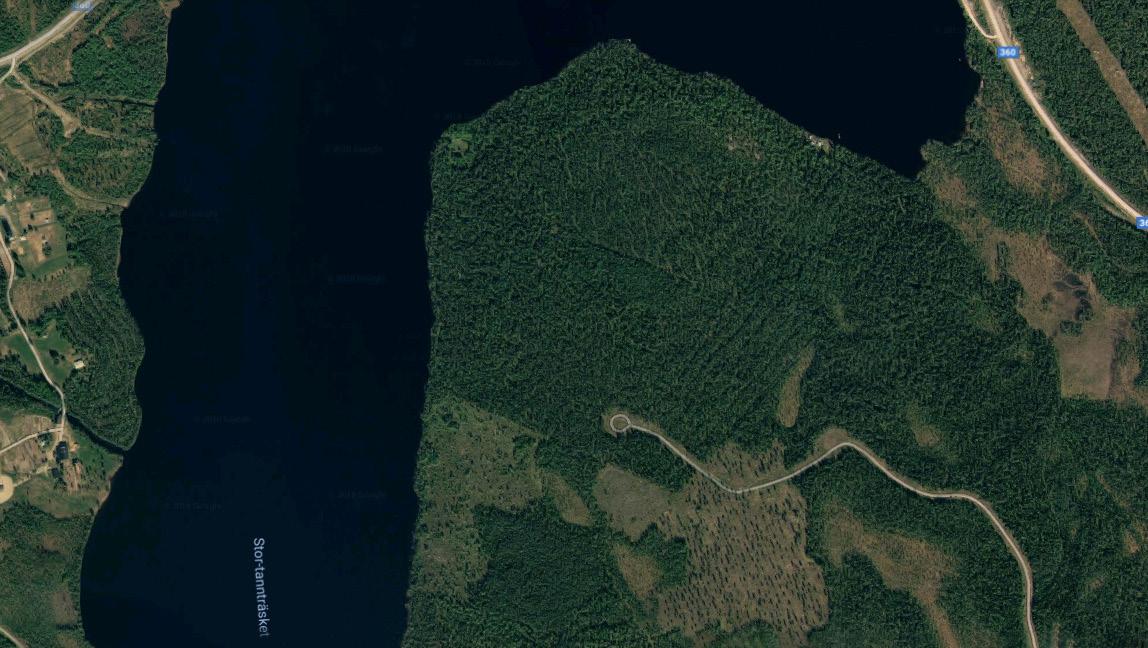
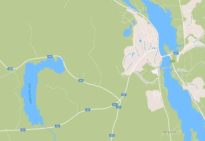
6 Km from Lycksele
SITE LYCKSELE N Location in Sweden
LYCKSELE 4
SITE
Solar studies of the site
The site and it’s closest city, Lycksele
A summer stuga
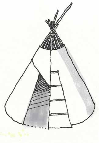
1.A traditional lavvu, as the basic inspiration.
The form is inspired from a traditional lavvu, the house of the Sami people, who live in the Laplands, and are idigenous to the region. The client has Sami ancestry, and she is more than happy to see a symbol of the Sami incorporated in the core design.
The conical shape of the lavvu is perfect for the allowed 35 sq.m. of construction. Also, its efficiency goes higher,
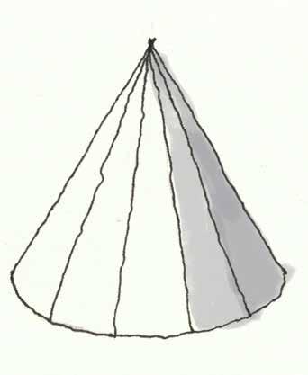
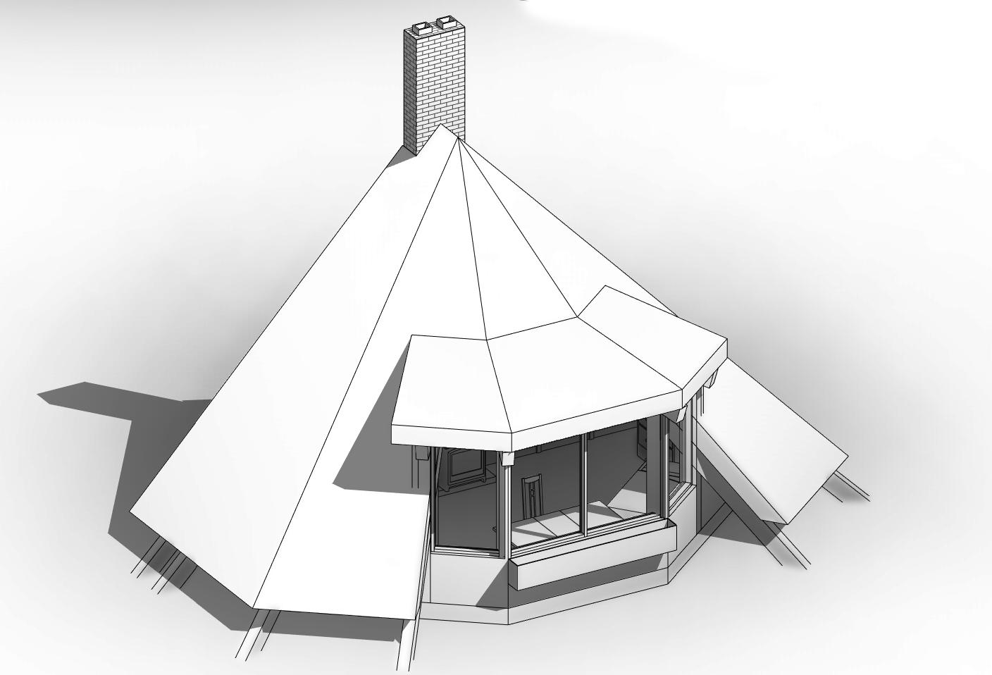
2. The typical conical shape is retained, the hides replaced with wood.
considering the objective is to create a compact, miniature house.
The addition of a fireplace with a wood stove presents its own challenges, especially if it’s in the center of a confined space. But cutting the cone along its diameter brings the fireplace out to one external surface, and opens up a world of possibilities.
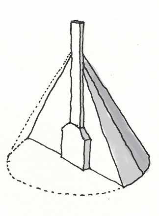
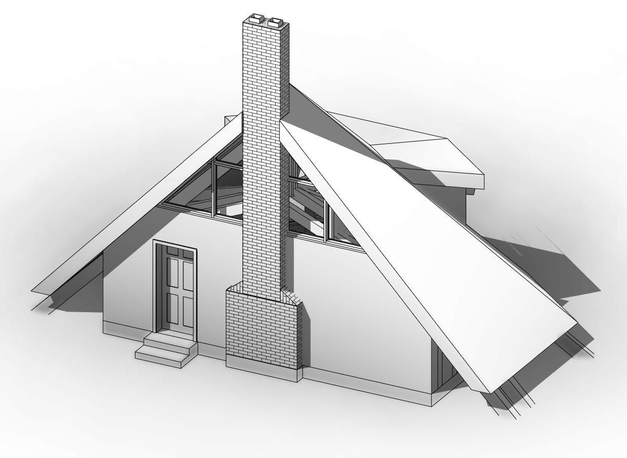
3. The cone is cut into half, and the central fireplace comes to one edge and a chimney can be placed.
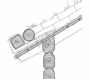
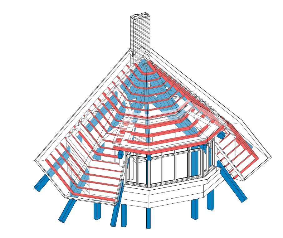
4. The concept drawing. The roof is supported by wooden trusses on wooden columns. The roof is sod roof, a typical grass-covered roof that keeps the interiors warm and dry during winters.
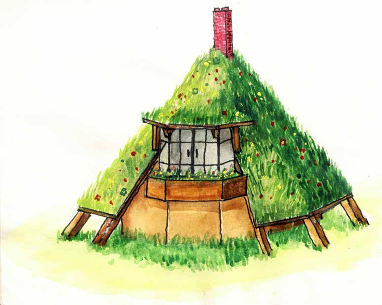
42
CONCEPT
A lavvu
43
450 1 2 3 D 6 5 4 7 8 A B C E F G 1374 1059 1417 1417 1059 1374 3045 324 2002 2530 2061 2061 582 450 450 1808 Area=35 Sq.m. Wood stove Brick chimney Desk Dresser Singlebed Bathroom Planter Roof projection above UP Floor Level 0 Verge Level 3000 NGL -300 Window cill 900 Plan of the stuga Section A-A Roof Verge detail
DRAWINGS
44
DRAWINGS
North elevation Floor Level 0 Verge Level 3000 NGL -300
Wooden Structural Framing
45
VIEWS
Southern view
Northern view

ABHISHEK RAY
B.Arch | M.Sc ITBE (ongoing)
Email: abhishekray4@gmail.com
Phone: +49 178 147 4445