COST-EFFECTIVE, SUSTAINABLE HOUSING LEH, LADAKH
THESIS BY: SYED KHWAJA ABID A/2880/2015
DEPARTMENT OF ARCHITECTURE SCHOOL OF PLANNING AND ARCHITECTURE, NEW DELHI 2020
2
NAME OF THE PROJECT
COST-EFFECTIVE, SUSTAINABLE HOUSING LOCATION
Leh, Ladakh, India
SITE AREA: 4.27 hectare BUILT-UP AREA: 26767sqm
GUIDES
COORDINATOR
Prof. Sandip Kumar, Prof. Mandeep Singh
Prof. Aruna Ramani Grover
THESIS BY
SYED KHWAJA ABID A/2880/2015
3
ABSTRACT The purpose of this research is to determine an optimal balance between sustainability and cost effectiveness for the cold and harsh climate of Leh, Ladakh. What initially started with a simple question quickly spiralled into a large spectrum of topics ranging from the most basic issues like how do we define sustainability to very complex ones like what is the optimal construction technique in Leh. The first difficult task was to breakdown the research into the topics to be explored. This was based on previous literature research and my personal biases on what direction I wanted my thesis to go. A plethora of topics were sorted and narrowed down to the most important ones as follows: Vernacular Architecture of Leh; Climate Responsive Architecture; Cost Effective construction techniques; Reusability in construction. As one may notice, the above topics were chosen such that they have a lot of overlap. Either one topic leads to another or may be used in tandem to achieve a greater result. The careful selection of these topics helped in shaping the thesis from the beginning. One may argue that I missed some major issues that need to be addressed by a housing project and I agree. This thesis is in no way a perfect representation of how housing should be done in Leh, but it is a step in the direction in which everyone needs to focus right now given the vulnerable state of its ecosystem. After sufficient research was complete, we moved on to designing a project that is more than a housing colony, it needed to be a habitat that can withstand all seasons without harming the fragile ecosystem. A habitat which wouldn’t force people to migrate in winters but to enjoy its beauty with all the possible comforts available. Keywords: Sustainability, Cost-effective, Housing, Climate-responsive, Optimal construction, Vernacular, Reusability, Habitat. 4
DECLARATION
The research work embodied in this Thesis report titled Cost-effective, Sustainable Housing has been carried out by the undersigned as part of the undergraduate Thesis programme in the Department of Architecture, School of Planning and Architecture, New Delhi, under the supervision of Mr. Sandip Kumar & Dr. Mandeep Singh. The undersigned hereby declares that this is his/her original work and has not been plagiarised in part or full form from any source.
Name of student: Syed Khwaja Abid Roll No.: A/2880/2015 Date: 22.06.20
CERTIFICATE
We certify that the thesis titled ‘Cost Effective, Sustainable Housing, Leh, Ladakh’ by Syed Khwaja Abid, roll no. A/2880/2015 was guided by us in January – June 2020 and placed in front of the Jury by the candidate on 29th and 30th July 2020. On completion of the report in all respects including the last chapter by the candidate and based on the declaration by the candidate hereinabove, we forward the report to the Department to be placed in the library of the School of Planning and Architecture, New Delhi.
Prof. Sandip Kumar (Design Guide)
6
Prof. Mandeep Singh (Design & Technology Guide)
ACKNOWLEDGEMENT
The research paper presented here would not have been possible without the guidance and support of Prof. Aruna Ramani Grover, coordinator for her relentless pursuit of high academic standards, the can-do attitude and imbibing professional ethics have helped this project to meet its completion. Thanks to Mr. Sandip Kumar & Dr. Mandeep Singh, guides for their continuous support and help in the framing of this report. My parents who supported me for going to Leh, Ladakh and encourage me in every new learning step I take. Thanks to Mr. Nisaar Kakpori from Public Works Department, Leh, Ladakh for helping me gather much required information about the Thesis site, context and the city. Special thanks to Ar. Rishav Paul, my mentor in Leh who shared with me his knowledge of Ladakhi architecture and supported me throughout the project whenever I had troubles. Thanks to Jigmet, Tashi, and Sonam for helping me during my visit to the Thesis site and case studies.
Syed Khwaja Abid A/2880/2015 School of Planning and Architecture, New Delhi Date: 22.06.20 7
TABLE OF CONTENTS DECLARATION & CERTIFICATE . . . . . . . . . . . . . . . . . . . . . . . . . . . . . . . . . . . . . . . . . . . . . . . . . . . . . . . . . . . . . . . . 5 ACKNOWLEDGEMENT . . . . . . . . . . . . . . . . . . . . . . . . . . . . . . . . . . . . . . . . . . . . . . . . . . . . . . . . . . . . . . . . . . . . . 7 TABLE OF CONTENTS . . . . . . . . . . . . . . . . . . . . . . . . . . . . . . . . . . . . . . . . . . . . . . . . . . . . . . . . . . . . . . . . . . . . . 8 TABLE OF FIGURES . . . . . . . . . . . . . . . . . . . . . . . . . . . . . . . . . . . . . . . . . . . . . . . . . . . . . . . . . . . . . . . . . . . . . . 9 1. INTRODUCTION . . . . . . . . . . . . . . . . . . . . . . . . . . . . . . . . . . . . . . . . . . . . . . . . . . . . . . . . . . . . . . . . . . . . . . . . 12 2. PROPOSITION . . . . . . . . . . . . . . . . . . . . . . . . . . . . . . . . . . . . . . . . . . . . . . . . . . . . . . . . . . . . . . . . . . . . . . . . .15 3. RSEARCH METHODOLOGY . . . . . . . . . . . . . . . . . . . . . . . . . . . . . . . . . . . . . . . . . . . . . . . . . . . . . . . . . . . . . . . . . 17 4. LITERATURE REVIEW . . . . . . . . . . . . . . . . . . . . . . . . . . . . . . . . . . . . . . . . . . . . . . . . . . . . . . . . . . . . . . . . . . . . . 18 4.1 A Fading Legacy: Ladakh’s Vernacular Architecture . . . . . . . . . . . . . . . . . . . . . . . . . . . . . . . . . . . . . . . . . . . . . . . 18 4.2 GERES Design Manual . . . . . . . . . . . . . . . . . . . . . . . . . . . . . . . . . . . . . . . . . . . . . . . . . . . . . . . . . . . . . . . . 19 4.3 Metamorphosis in Construction Techniques of Trans-Himalayan region of Leh, Ladakh (Jammu and Kashmir) . . . . . . . . . . . . . .20 5. CASE STUDIES . . . . . . . . . . . . . . . . . . . . . . . . . . . . . . . . . . . . . . . . . . . . . . . . . . . . . . . . . . . . . . . . . . . . . . . . 22 5.1 Matho Palace . . . . . . . . . . . . . . . . . . . . . . . . . . . . . . . . . . . . . . . . . . . . . . . . . . . . . . . . . . . . . . . . . . . . . 22 5.2 Druk Padma Karp School . . . . . . . . . . . . . . . . . . . . . . . . . . . . . . . . . . . . . . . . . . . . . . . . . . . . . . . . . . . . . . 31 5.3 Solar Colony . . . . . . . . . . . . . . . . . . . . . . . . . . . . . . . . . . . . . . . . . . . . . . . . . . . . . . . . . . . . . . . . . . . . . .35 5.4 House of Families . . . . . . . . . . . . . . . . . . . . . . . . . . . . . . . . . . . . . . . . . . . . . . . . . . . . . . . . . . . . . . . . . . . 41 5.5 Zero Energy Demonstration Home . . . . . . . . . . . . . . . . . . . . . . . . . . . . . . . . . . . . . . . . . . . . . . . . . . . . . . . . .44 6. SITE ANANLYIS . . . . . . . . . . . . . . . . . . . . . . . . . . . . . . . . . . . . . . . . . . . . . . . . . . . . . . . . . . . . . . . . . . . . . . . . 48 7. Technological Drivers . . . . . . . . . . . . . . . . . . . . . . . . . . . . . . . . . . . . . . . . . . . . . . . . . . . . . . . . . . . . . . . . . . . . 58 7.1. Structure . . . . . . . . . . . . . . . . . . . . . . . . . . . . . . . . . . . . . . . . . . . . . . . . . . . . . . . . . . . . . . . . . . . . . . . .59 7.2. Services . . . . . . . . . . . . . . . . . . . . . . . . . . . . . . . . . . . . . . . . . . . . . . . . . . . . . . . . . . . . . . . . . . . . . . . .62 7.3. Sustainability . . . . . . . . . . . . . . . . . . . . . . . . . . . . . . . . . . . . . . . . . . . . . . . . . . . . . . . . . . . . . . . . . . . . . 62 8. VISION . . . . . . . . . . . . . . . . . . . . . . . . . . . . . . . . . . . . . . . . . . . . . . . . . . . . . . . . . . . . . . . . . . . . . . . . . . . . . 69 9. DESIGN DEVELOPMENT . . . . . . . . . . . . . . . . . . . . . . . . . . . . . . . . . . . . . . . . . . . . . . . . . . . . . . . . . . . . . . . . . . . 71 10. FINAL DESIGN . . . . . . . . . . . . . . . . . . . . . . . . . . . . . . . . . . . . . . . . . . . . . . . . . . . . . . . . . . . . . . . . . . . . . . . . 76 11. SYNOPSIS & JURY REMARKS . . . . . . . . . . . . . . . . . . . . . . . . . . . . . . . . . . . . . . . . . . . . . . . . . . . . . . . . . . . . . . . 106
BIBLIOGRAPHY . . . . . . . . . . . . . . . . . . . . . . . . . . . . . . . . . . . . . . . . . . . . . . . . . . . . . . . . . . . . . . . . . . . . . . 109 8
TABLE OF FIGURES Figure 1: Entrance to the palace and south facade . . . . . . . . . . . . . . . . . . . . 19
Figure 26: Inside of a module . . . . . . . . . . . . . . . . . . . . . . . . . . . . . . . 33
Figure 2: South Facade . . . . . . . . . . . . . . . . . . . . . . . . . . . . . . . . . . . 20
Figure 27: Standalone module . . . . . . . . . . . . . . . . . . . . . . . . . . . . . . . 33
Figure 3: Stone foundation uptil plinth level . . . . . . . . . . . . . . . . . . . . . . . 20
Figure 28: Frost formation on window . . . . . . . . . . . . . . . . . . . . . . . . . . . 33
Figure 4: Eastern facade of Matho Palace showing mud bricks (pakbu) under
Figure 29: Water condensing on the roof . . . . . . . . . . . . . . . . . . . . . . . . 34
the plaster . . . . . . . . . . . . . . . . . . . . . . . . . . . . . . . . . . . . . 21 Figure 5: Shinsak above a window having 5 layers. Black plaster around the opening21 Figure 6: 1st Floor Plan, Matho Palace . . . . . . . . . . . . . . . . . . . . . . . . . . . 22 Figure 7: 1st Floor RCP, Matho Palace . . . . . . . . . . . . . . . . . . . . . . . . . . . 23 Figure 8: 2nd Floor Plan, Matho Palace . . . . . . . . . . . . . . . . . . . . . . . . . . 24 Figure 9: 2nd Floor RCP, Matho Palace . . . . . . . . . . . . . . . . . . . . . . . . . . 25 Figure 10: Elevations, Matho Palace . . . . . . . . . . . . . . . . . . . . . . . . . . . . 26 Figure 11: Sections, Matho Palace . . . . . . . . . . . . . . . . . . . . . . . . . . . . . 27 Figure 12: Site Plan, Druk Padma Karpo School . . . . . . . . . . . . . . . . . . . . . 28 Figure 13: Central basketball court . . . . . . . . . . . . . . . . . . . . . . . . . . . . 29 Figure 14: 3 idiots wall . . . . . . . . . . . . . . . . . . . . . . . . . . . . . . . . . . . . 29 Figure 15: Section of a classroom, Druk Padma Karpo School . . . . . . . . . . . . . 29 Figure 16: Structural Engineer, Connor McGrath explaining the joinery detail . . . . 30 Figure 17: Base of a pillar showing the gazette pl ate and the piece of plastic
coming out from the sides . . . . . . . . . . . . . . . . . . . . . . . . . . . 30 Figure 18: Detail showing the rectangular primary beam and the circular
secondary beams resting on it. . . . . . . . . . . . . . . . . . . . . . . . . 30 Figure 19: Inside the dining hall . . . . . . . . . . . . . . . . . . . . . . . . . . . . . . . 31 Figure 20: Metal sheet wall behind the toilets . . . . . . . . . . . . . . . . . . . . . . . 31 Figure 21: Huge solar cooker . . . . . . . . . . . . . . . . . . . . . . . . . . . . . . . . 31 Figure 22: Section of toilet wall . . . . . . . . . . . . . . . . . . . . . . . . . . . . . . . 31 Figure 23: Site for neighbourhood park . . . . . . . . . . . . . . . . . . . . . . . . . . 32 Figure 24: Row of modules . . . . . . . . . . . . . . . . . . . . . . . . . . . . . . . . 33 Figure 25: Foundation blocks . . . . . . . . . . . . . . . . . . . . . . . . . . . . . . . 33
Figure 30: Water dropping down and freezing. . . . . . . . . . . . . . . . . . . . . . 34 Figure 31: Module attached to mud brick, timber structure . . . . . . . . . . . . . . 34 Figure 32: Attachment from inside the house . . . . . . . . . . . . . . . . . . . . . . 34 Figure 33: Toilet block on the right of the module . . . . . . . . . . . . . . . . . . . . 34 Figure 34: Solar Colony, Choglamsar- complete proposal . . . . . . . . . . . . . . 36 Figure 35: Solar Colony, Choglamsar- existing satellite image . . . . . . . . . . . . . 37 Figure 36: 3D render, House of Families . . . . . . . . . . . . . . . . . . . . . . . . . . 38 Figure 37: Section of a typical block . . . . . . . . . . . . . . . . . . . . . . . . . . . 39 Figure 38: Site Plan. House of Families . . . . . . . . . . . . . . . . . . . . . . . . . . 40 Figure 39: Zero Energy Demonstration Home . . . . . . . . . . . . . . . . . . . . . . .41 Figure 40: The home’s shell consists of two exterior walls, insulated both
between the studs of each wall and in the space between each wall, providing superior heat retention. . . . . . . . . . . . . . . . . . . . . . . 42 Figure 41: These raised trusses at the intersection of the wall and roof frames
allowed for 2 feet of insulation to be blown into the attic. . . . . . . . . . 42 Figure 42: Percentage of Sun-Radiation recieved by each face of the building
in Ladakh region . . . . . . . . . . . . . . . . . . . . . . . . . . . . . . . . 56 Figure 43: Distant Obstructions . . . . . . . . . . . . . . . . . . . . . . . . . . . . . . 56 Figure 44: Nearby Obstructions . . . . . . . . . . . . . . . . . . . . . . . . . . . . . . 56 Figure 45: Optimal surface to volume ratio . . . . . . . . . . . . . . . . . . . . . . . . 57 Figure 46: Thermal Insulations . . . . . . . . . . . . . . . . . . . . . . . . . . . . . . . 59 Figure 47: GluLam Beam, Shapes & Quality . . . . . . . . . . . . . . . . . . . . . . . . 61 Figure 48: Scarf Joint (left) & Finger Joint (right) . . . . . . . . . . . . . . . . . . . . . 61 Figure 49: Joints in Lamination (Scarf Joint) . . . . . . . . . . . . . . . . . . . . . . . . 62
9
Figure 50: GluLam Manufacturing Process . . . . . . . . . . . . . . . . . . . . . . . . 62 Figure 51: External wall section of timber frame construction . . . . . . . . . . . . . . 63 Figure 52: Timber frame structural system combining GluLam load bearing
members with traditional roofing system. . . . . . . . . . . . . . . . . . . . 64 Figure 53: External wall section showing poured earth panels on timber frame
cavity wall. . . . . . . . . . . . . . . . . . . . . . . . . . . . . . . . . . . . . 65 Figure 54: External wall section showing active solar space heating technology. . .
10
65
11
1. INTRODUCTION COST EFFECTIVE HOUSING Cost effective Housing is a concept which deals with effective budgeting and following of techniques which help in reducing the cost construction through the use of locally available materials along with improved skills and technology without sacrificing the strength, performance and life of the structure. It has more to do with budgeting and seeks to reduce construction cost through better management, appropriate use of local materials, skills and technology but without sacrificing the performance and structure life. It should be noted that low cost housings are not houses which constructed by cheap building materials of substandard quality. The reduction in cost is achieved through effective utilization of locally available building materials and techniques that are durable, economical, accepted by users and not requiring costly maintenance. Economy is also achieved by postponing finishing and implementing low cost housing technologies in phases. High efficiency of workers, minimize waste in design and apply good management practices, can also be achieved. Achieving cost effectiveness has a lot to do with the building design itself as not all designs can be constructed using the materials and techniques which are required to do so. Therefore, the role of the architect is key in such projects to deliver a design that can be realised keeping all the restrictions in mind to create unique oppurtinities for innovative usage of available resources. Cost effective designs often go for a simplistic approach with cubical forms but that is not a mandatory requirement as far as the design resonates with the materials and the technique while keeping only the details simplistic to make the construction faster and cheaper. The building construction cost can be broadly divided into two parts, namely: 1. Building material cost 2. Labour cost 12
Now in cost effective housing, building material cost might be less if we make use of the locally available materials, rectifying a few logistical costs, and also the labour cost can be reduced by hiring local labourers and properly making the time schedule of our work. The use of locally available materials my also give us several more advantages as the local labour must be well acquanted with them, it will support the local economy, and reduce the overall carbon footprint of construction. Reduction of cost is achieved by selection of more efficient material or by an improved design. Low cost housing technologies aim to cut down construction cost by using alternatives to the conventional methods and inputs. It is about the usage of local and indigenous building materials, local skills, and energy saving methods. ‘Managing the response to the ever increasing housing needs of Indian population expanding by 1.3% every year, has long been a problem for its government. Providing affordable housing remains a major concern of the government as 37% of its population remains below the International poverty line (US $1.5 a day).’ (Chowdhury, Roy 2013) SUSTAINABLE HOUSING The rapid urbanization has put pressure on the finite resources and is characterized by severe shortage of basic services like potable water, well laid-out drainage system, sewerage network, sanitation facilities, electricity, roads and waste disposal. Thus, unplanned and unsustainable urban development has led to severe environmental pressures. ‘By 2050, India is likely to be the most populous country with a projected population of 1.69 billion. It is estimated that over 70 million new urban housing units will be needed over the next 20 years in India. This unprecedented urbanization has grave implication for ecological, economic sustainability.’ (Singh, Pandey 2012)
‘Sustainability can be defined as meeting the needs of today without compromising the needs of future generations.’ (World Commission on Environment and Development 1987) According to the World Summit on Social development, 1995, sustainalbile development has 3 pillars, namely economic development, social development, environmental protection. This idea lead to the concept of the 3Es of sustainable development i.e. Equity, Economics, and Environment. So sustainability can be broken down and understood as achieving the perfect balance between these 3 pillars. Several commentors have added a fourth pillar to this concept that is cultural appropriateness which needs to be taken into concern especially in places with rich cultural histories. (Goodhew Steve, 2016) Social development and equity can be achieved by making sure that all essential resources and infrastructure be accessable to all in the society. Economic sustainablity can be assured if the overall expenditure of construction balances the profit through income and the long term running costs are minimized while creating more oppurtunities of income thus supporting the local economy. Environmental sustainability may be achieved by minimizing the carbon footprint during procurement and construction phase and also designing energy efficient habitats to reduce the pressure on local natural resources. This will ensure that nature gets enough time to replenish and sustain for the future. This needs to be a prioirity especially in ecologically sensitive zones. Thus, sustainable housing must aim at economic, social and environmental sustainability from planning to implementation phase and at the same time result in housing that is accessible and environmentally less damaging. Can cost effective housing be sustainable? Government projects mainly try to reduce expenditure by increasing speed of construction and minimizing operational costs of construction. They may try to use cheaper construction materials or materials which reduce the time of construction even if the material is not ecologically viable in the context. Using such materials may also ultimately increase the running cost of the building as energy efficiency is not a priority. Granted, the immediate costs are low, but the toll on the environment in
the long run is dreadfully high. We may be getting faster at rolling out low cost housing solutions but there are far worse negative consequences. Globally, the construction industry is contributing to 23% of the air pollution, 40% of water pollution, 50% of landfill pollution, and responsible for 50% of the climatic change. (Bimhow blog) In another research by the U.S. Green Building Council (USGBC), the construction industry accounts for 40% of worldwide energy usage. The condition is not much better in India. Let’s take the example of the national capital, Delhi, where the Delhi Pollution Control Committee (DPCC) claims that 30% of air pollution is caused due to dust which emanates from construction sites. The Indian government has set guidelines for construction site owners to minimize the environmental impact but it’s not enough. There is a lack of proper adhering of these guidelines as the administration doesn’t take strict measures against the ones who don’t follow it. (Borana Rashi, 2019) If the administration is not able to make sure these guidelines are being followed in the national capital, just imagine the scenario in tier 2 and tier 3 cities. We’re all paying a very steep price for the faster construction speed and savings in expenditure. It’s time we pull back the lens and scope the issue wider, so we can redefine what this country can actually ‘afford’. Overpopulation is an ever-growing problem in the nation, more than ever, we simply need cheap roofs over heads but the solution is not to slap down brick and mortar faster. A better solution is to design within the context of sustainability and lifestyle. If we want to ensure healthy cities, we have to build with green space and human connectivity in mind. Can sustainable housing be cost effective? Popular perception associates sustainability with expensive technological advances.(Seth Sanjay, 2020) The global green building movement that started about two decades back was triggered by the need to curb extravagant resource consumption in modern buildings. However, affordability lies at the core of sustainability. Common sense 13
entails that if something cannot be reduced, reused, repaired, rebuilt, refurbished or recycled, it should be restricted or removed from production. Thus, sustainability is not an option but is the only way forward for local low-cost innovations. Investment in clean and efficient infrastructure can contribute to decarbonisation and rational resource usage. For instance, improved day lighting can reduce energy demand for artificial lighting and hence electricity bills. Double-glazed windows are costly but provide insulation from heat, dust and sound and are cheaper to maintain in the long run. Consumers must create market demands for sustainable housing by objectively considering sustainability as “the right thing to do.” Unfortunately, lack of understanding sparks suspicion around proposed solutions being truly green or not.
14
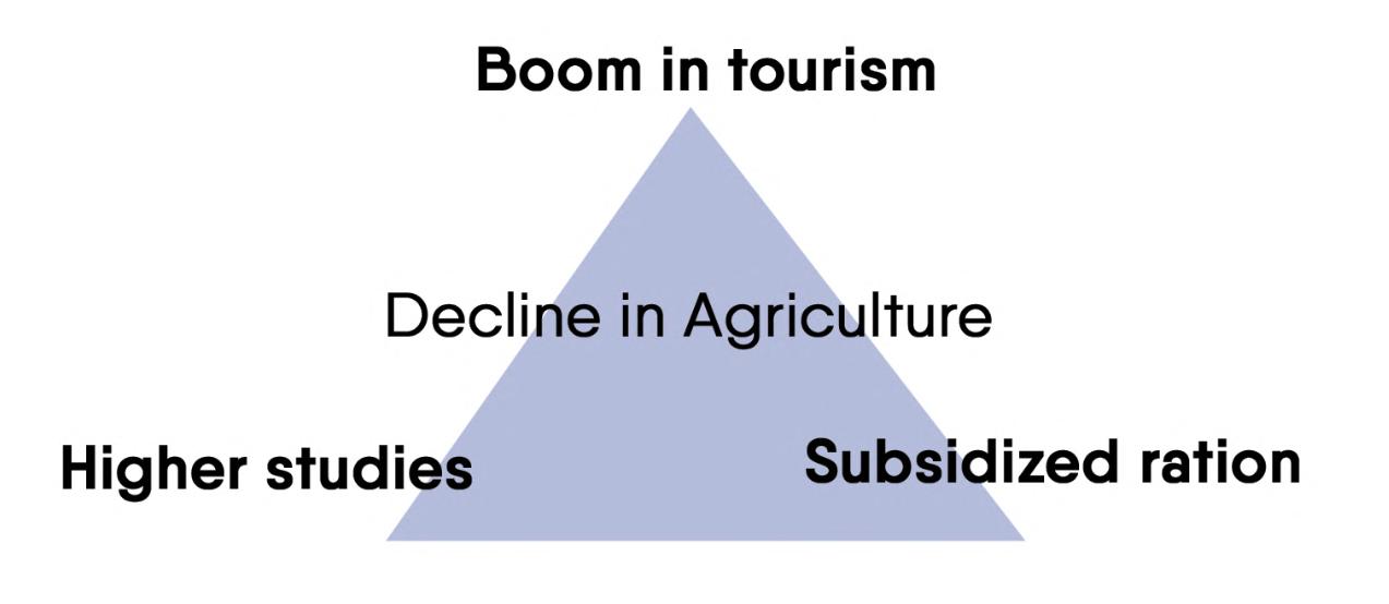
2. PROPOSITION In the last decade, Leh experienced a boom in tourism and demand of guest houses and hotels increased rapidly resulting in locals opting for a material which allows a faster speed of construction, concrete. We have already established how the construction industry is responsible for a large percentage of air and water pollution. Moreover, it also consumes a lot of water in preparation, curing, etc. which has overused the amount of water available in the already water scarce region. This pollution contributes to global warming which in turn is leading to climate change in the region. The climate over Leh shows a warming trend with reduced precipitation in the current decade. (Chevuturi, Amulya & Dimri, 2016) Rapid urban growth has also led to the inevitable depletion of natural resources, water being the affected the most. Leh is a cold dessert with an annual rainfall of less than 10mm, the only source of water for the city is the glacier melt. The renewal rate of water cycle finds it impossible to match up to the usage rate of water, resulting in depletion of water table each year.(Ladol Padma, 2019) Soon, agricultural production in the Leh valley will decline to such an extent that villagers will need to migrate to other cities for employment, therefore there is an urgent need for sustainable architecture which focuses on the judicious use of resources and energy. The boom in tourism industry attracted native population from neighbouring villages and towns to migrate to Leh city in search of new job opportunities and due to this increase in population the government is trying to set up adequate amount of social and physical infrastructure in and around the city to cater to its needs. This creates a demand of large scale housing for natives of neighbouring areas, non-natives from far away regions, and government officials appointed to work for the city. All the above mentioned groups require affordable homes which need to be made available as soon as possible.
Problem Statement: To design a cost effective housing solution that caters to the growing population of Leh city that can withstand the extreme cold and harsh climate and at the same time is socially, economically, and environmentally sustainable. PROPOSAL: CPWD GOVERNMENT HOUSING QUARTERS The Trans Himalayan region of Ladakh recently got separated from Jammu and Kashmir and acquired the status of Union Territory. This opens up opportunity for a great amount of development in the area, especially in Leh, the capital. The first step of the newly elected Lieutenant governor would be infrastructure building for the entire city. Several new government offices need to be set up and housing needs to be provided for this immigrating population. This is not just another generic government housing project. This is the first CPWD housing project in the new Union territory of Ladakh and thus, will serve as a reference for all future projects in the region. Union Housing and Urban Affairs Ministry has sought a detailed proposal from the local administration to execute various development projects in Leh and Kargil regions. An official said the ministry is also contemplating to include these two regions under its ‘Smart City Mission’, a flagship programme of the government. The Central Public Works Department (CPWD), a prime construction agency of the central government, offered the Jammu and Kashmir administration assistance in building “economical” and “best quality” infrastructure in the two union territories. 15
The CPWD is in full swing to make this proposal a benchmark for low cost housing construction which will be used as reference for upcoming housing projects in the region. Additions to the proposal: 1. In addition to being low-cost, the project must be sustainable and energy efficient so that it is truly low-cost in the long run. This means that the construction should not create as much carbon footprint which could harm the sensitive ecology of the area; at the same time, it should handle the cold and harsh climate with minimum external energy for heating and electricity. 2. The process of construction can be optimized to maximize the efficiency of time and resource management on site. This itself could have a significant impact on the cost of construction. 3. Alternate materials which are locally available need to be explored and used in innovative ways to reduce the cost as well as the carbon footprint of the project. We should examine vernacular construction techniques that were able to achieve harmony with the environment for hundreds of years. 4. Construction techniques that may be reusable or automated at a large could be explored to speed up the process even more and increase the design’s (element or module) reusability in future projects of the CPWD.
16
17
3. RSEARCH METHODOLOGY
4. LITERATURE REVIEW Vernacular materials and building techniques: 4.1 A Fading Legacy: Ladakh’s Vernacular Architecture (by Eduardo Paolo Ferrari 2015) This dissertation is an exceptionally detailed study of the architecture and culture of Ladakh. The author discusses the vernacular heritage and building methodologies which are essential to creating the sustainable architecture of the future. The part of the research I am particularly interested in is the ‘Basic Principles for the Construction of a House’. The chapter describes principles such as: - Orientation of the house to capture maximum solar radiation in winters; - Plan-scheme which adapts itself to the terrain and is feasible with the structural system; - Construction process using traditional materials and tools; - Dimensions and shape of rooms. The house form is derived by the structural system as well as the function of each space whereas the function is derived from the traditional Ladakhi way of living which the author experienced firsthand by living with a Ladakhi family in their house and studying the culture which has been passed on for years. The author further writes about the function of each space in the house, the most important of them being the Chansa, the fireplace room. The chansa includes the cooking area, a seating area like a living room, and a traditional 18
firewood burner called Bhokhari. The room is significantly larger than any other room in the house and requires a pillar in the centre to support the primary beam. The pillar virtually divides the room into two parts, separating the cooking/ storing area from the living room area. The location of the fireplace room (which has no windows except a hole in the ceiling for the bokhari chimney)in either on the ground floor surrounded by stables or on the first floor surrounded by storerooms or bedrooms to provide a buffer space which acts as insulation. The house has a suitable location for each room according to their function and the amount of thermal comfort it demands. Other spaces in the house include stables, storage rooms, guest room/Rabsal room, toilet, sun-room, sleeping room, terraces, and prayer room. The chapter which particularly interests me is ‘House elements and Construction Technology’ which overviews traditional materials and techniques. Earth is the most vital material of construction, used in sundried bricks, as binding material, and for plastering. The selection of soil depends upon the proportion of its components, following which it mixed with water, hand moulded and sun-dried to make compressed earth blocks traditionally known as Pakbu. Wood is the structural material obtained from the two most widely grown trees in Ladakh, Poplar for pillars(ka) and beams(dungba) and Willow for purlins(taalu) in the roofing. It is also used for ornamentation elements such as kaju, the pillar head and the shinsak, a lintel element over windows. Stone is used mostly in shallow foundations and a few other places like the coping of the parapet wall and may also be used
for flooring. All these materials are locally available very easily but the locals prefer concrete construction for it provides an advantage of lesser construction time.
building orientation or obstructions which block the direct sunlight, it is best to equip the building with adequate thermal insulation. There are two components of EEB construction-
A detailed understanding of traditional building techniques allows us to understand the Passive Solar Building technology because the underlying principles of both these methodologies are more or less the same. Ferrari further went on to convert his dissertation into a book, ‘High altitude houses: Vernacular Architecture of Ladakh’ which I highly recommend if one is interested in exploring the link between the cultural heritage and architecture of Ladakh.
a. Insulation to retain indoor heat and prevent heat loss; b. Ventilation to supply fresh air to inhabitants. In order to attain a comfortable room temperature, it is important to supply heat inside the building. The amount of energy required to heat the building is equal to the difference between the heat loss (by ventilation and heat infiltration) and heat gain (by solar and indoor gains) of the building. Heating Energy Demand = Heat loss - Heat gains From this equation we can easily understand the strategy of EEC buildings which is to reduce the heat loss and maximize the heat gains, thus reducing the amount of energy required to heat up the building i.e. the heating energy demand. As the heating demand decreases, so does the heating consumption of the building which results in the increase in the efficiency of the system. The relation between these three can be derived asHeating consumption = Heating Energy Demand / Global Heating System Efficiency
4.2 GERES Design Manual Passive Solar basics According to the GERES Design manual (2012), Low Energy Consuming (LEC) building techniques can be adapted to the cold and dry climate of the trans himalayan region to provide comfortable living conditions even in winters. There are two main types of LEC constructions family that can be implemented in Indian Himalayas: 1. Energy Efficient Buildings (EEB): Type of construction that integrates only thermal insulation. 2. Passive Solar Buildings (PSB): Type of construction that integrates passive solar architecture with thermal insulation.
According to the experience of GERES India about energy efficiency in Indian Himalayas- PSB techniques can annually save up to 70% of heating energy; - EEB techniques can annually save up to 45% of heating energy. Thermal comfort is generally increased in LEC buildings.
1.1. Energy Efficient Building Concept: When it is not possible to properly collect solar radiation, due to bad 19
Alternative materials: CSEB; Earthen construction
towards the east which is not sufficient to gain enough solar radiation.
4.3 Metamorphosis in Construction Techniques of TransHimalayan region of Leh, Ladakh (Jammu and Kashmir)
The author has a peculiar liking for earthen construction. It includes
(by Gurjot Singh Chawla 2017) According to the opinion survey executed and documented in this dissertation, almost 75% of the locals in Leh city rent out their homes during peak tourist season and 34% people prefer a concrete house over the traditional earth and wood construction. Over the last three decades, the population of Leh has grown thirteen times its original amount as is continuing to do so which is mainly because of the boom in the tourism industry and immigrant population from neighbouring villages which caters to the large tourist population in the summer months. The municipality is not adequately equipped to handle the pressure on the natural resources of the valley and there is an acute shortage of infrastructure in the city. Urban sprawl is evident and ever increasing as the locals build more and more guest houses to accommodate more tourists. The pure concrete construction which is done mainly to construct faster is not at all suitable for the harsh winters of Leh. The conductive properties of concrete allow it to cool down very fast, losing all the indoor heat gains at night time and artificial heating is a must in such a building. Architecture is a rare profession in Leh where contractors and structural engineer make plans at minimal rates and sell it to guest house owners. Generalizing these designs as bad could be a wrong statement but most of them ignore the basic principles of passive solar building design which is essential in Leh more than anywhere else in India. For example, the author addresses a hotel which has the biggest glass windows faced 20
construction techniques like rammed earth, adobe (sun-dried earth bricks), wattle and daub, and cob. All of these are traditional building methodologies which work efficiently in the summers as well as winters. Modern building materials discussed in the dissertation are CSEB and cement blocks. There are several innovative building techniques being used in modern construction in and around Leh, for example insulation through pashmina wool, a waste byproduct generated at the pashmina mill which is cheap and effective to trap air bubbles; Trombe wall combined with double glazing which increase solar heat gain and also works as insulation; Plastic wire mesh which is laid horizontally after every two feets in a rammed earth wall to strengthen it and give it a longer life (steel mesh is not used because of its high conductivity); Hollow concrete blocks which are not sustainable but much more lighter than the typically used concrete block, and the air inside the block provides insulation. The greatest resource of this dissertation is the multiple case studies of both traditional architecture and sustainable modern architecture in Leh, Ladakh. The vernacular methodologies of construction are adapted according to the climate and the topology but still has some flaws because of which people make a deliberate choice of switching to modern materials. Research needs to be done on techniques using these modern materials to make the architecture more energy efficient and environment-friendly. The author discusses thermal comfort and compares the vernacular materials to be better than modern materials but does not give enough data to deduce which methodology is more
cost effective and has a lesser negative impact on the environment. We have now attained a basic understanding of Passive Solar Building design and what kind of techniques can be implemented in the cold and dry climate of Leh. Research needs to be done on the properties of traditional and modern building materials to analyse and compare these materials on the basis of: - Thermal Conductivity (through which we can also determine their Insulation Level); - Thermal Mass (Energy storage capacity and time taken to release it). Leh receives ample sunlight during the whole year and extensive design innovations have been implemented in the Passive Solar buildings in the region, for example, the SECMOL campus, LEDeG’s Ecology Hostel, the Druk Padma Karpo school campus. A detailed case study of any one of these buildings will help us in understanding the efficiency of PSB in the Ladakh region. We have studied about design methodologies to make a building energy efficient but we have still not discussed its materials. A construction material is required which can speed up the overall process and is environment-friendly as well. Using concrete blocks and RCC. frame in building construction makes the process much faster but the lifespan of such buildings is just about 50 years after which it starts to deteriorate. What happens to a building which starts to fail structurally and can no longer function? It is demolished and a new building is constructed over it, but what happens to
a certain extent. It can be crushed to form an aggregate to be used as a base course for footpaths, driveways, under building foundations, soak pits, drainage channels, etc. (BRANZ rebri) Concrete is non-biodegradable, therefore if it not reused it is a great hazard to the environment. The solution to this issue has been in front of us all along. The traditional way of building in Ladakh used the Earth as a building material which is much more cheaper, abundantly available and completely biodegradable. The only problem with rammed earth construction, the way it was traditionally done is that it is very labour intensive and requires a lot of time. CONCLUSION This literature review covers the construction techniques and building materials which are currently being used in Leh, Ladakh. It also discusses the vernacular architecture of Ladakh, its relation to the local culture and its declining popularity in the present context. The need of the hour is to introduce materials which do not harm the already scarce natural resources and also speeds up the construction process as per the growing needs of tourism.
the debris? Although most materials from a demolition site can be reused or recycled, these practices are not known of in most parts of the country including Leh, where most of the salvageable debris is dumped into the landfill at Bomgard. Concrete is reusable but only to 21
5. CASE STUDIES Primary Case Studies
5.1 Matho Palace Matho
Figure 55: Entrance to the palace and south facade Source: Author
21 Kilometers from Leh city is a small village named Matho. Up over the hill are Matho Gompa and the newly built Matho Museum and tower. In the lower wetlands, hiding in plain sight is the Matho Palace, the former of Kushok Bakula Rimpochee after whom the Leh airport is named. The Palace is an old, abandoned four storeyed structure made of adobe, stone and wood. The building is the testimony of how much the vernacular architecture of Ladakh is resilient to the forces of nature.
used through which the water can rise. Dry stones can be laid and interlocked without mortar to prevent any penetration of water in areas with higher groundwater level.
1.1. STRUCTURE: The major Phases of Construction are as follows: 1. Collection of materials; 2. Digging and laying foundation; 3. Making walls with openings and lintels; 4. Placing pillars (Ka), primary beams (Dumba), and purlins (taalu) and floors; 5. Fitting of windows and doors; 6. Plaster and Decorations. 1.1.1. FOUNDATION: If the house is on flatland like in the case of Matho Palace, it requires foundation uptil plinth level to prevent capillary action of groundwater. After the digging, undressed stone is laid using mud mortar as binding element. The larger stones are laid first and the size of stone decreases as the wall rises and stones are positioned such that they interlock to create stronger foundations. The depth of foundation depends upon the type of soil. In case of ‘hard soil’, shallow foundations may work which are 1-2ft deep but in our case, the building is on ‘soft soil’ near a stream and require a deeper foundation which is 2-3ft for a small house but should be at least 5ft for a structure this big. The foundation width was traditionally much wider than contemporary buildings since the mud walls were much thicker and brick walls built today. The width of foundations should be 4-5ft. The presence of water in the soil can be an issue because of the mortar
Figure 56: South Facade
Figure 57: Stone foundation uptil plinth level
Source: Author
Source: Author
1.1.2. WALLS: Earth walls are structural members as well as insulation. For a 4 storeyed structure, the walls must be thicker to assure the stability of the building. The thickness of the walls also decreases as we go to higher levels. Partition walls are thinner as they take a lesser load. Walling of each floor is completed while leaving openings and wooden lintels before floor laying. The Matho Palace walls are made of sundried mud bricks (pakbu). Soil is selected which has high moisture and clay content. Hay, animal hair or clay (markalag) is added to the mixture to act as binding materials. Earth and water are mixed to get a paste which is molded into a brick and then sundried. This mixture should be perfectly proportioned and require experienced labour. After sun-drying for 10-15 days, the bricks are cured for 3-5 days and then layed using mud mortar. Old mud bricks are reusable and can be broken and mixed with water to obtain the paste. 23
prevent the absorption of moisture from the ground in the wooden column. Wooden elements are connected with tongue and groove joints which have a better response to earthquakes as they provide a slight play between two wood elements. 1.1.5. FLOOR:
Figure 58: Eastern facade of Matho Palace showing mud bricks (pakbu) under the plaster Source: Author
Figure 59: Shinsak above a window having 5 layers. Black plaster around the opening Source: Author
1.1.3. OPENINGS: In a place with extremely cold weather during winters, openings in a building should be well planned to maximize the solar radiation captured and minimize the loss of heat from inside the building. Most of the windows are on the south and east side whereas rooms which do not require more natural lighting or insulation are positioned on the north and west side of the building. Smaller windows are provided on the ground floor since its inhabited by cattle, whereas first floor and above have bigger windows to increase wooden components and reduce wall volume, in turn, reducing the dead load of walls. Window frames which are made using purely wooden joinery are prepared in advance and put up in its designated place after wall construction. Openable wooden shutters are also provided. Poplar wood was made into planks to make all door and window frames and shutters. 1.1.4. BEAMS AND COLUMNS: Ladakhi buildings follow a trabeate structural system where primary beams (dumba) are rested over walls and in case the span exceeds 15-16ft, a column (ka) is put in the middle of the span. The column capital (kaju) helps in transferring the load from beam to the column. On the ground floor, the ka stands on a stone base extruded 2-3inches off the ground to 24
The floor consists of the following elements: 1. Beams (Dumba) 2. Purlins (Taalu) 3. Non-rotting hay or shrubs 4. Mud The above is also the sequence of laying at the time of construction. Dumba is made of poplar which are long trees with trunks of about 6inch diameter. There should always be an odd number of Dumbas in a room as the odd numbered beam is associated with happiness and the alternative even beam is associated with sadness. Although, there is also a practical reason for an odd number of dumbas is that the mason with first lay the middle dumba to divide the room in two and then further subdivided always keeping them odd in number. Taalu comes from the willow tree branches which are periodically cut as they grow back every season. Taalu can be laid diagonally or in patterns which give the space an elegant feel. 1.1.6. PLASTER: Mud plaster is put on both inner and outer sided of the wall. Mud with higher clay (markalag) content ie. around 5%, is better for plaster work as it sticks to the wall well and doesn’t easily crack. Earth can be mixed with hay or animal dung to enhance its stability and insulation. Plaster is applied in layers, alternatively horizontal and vertical. The thickness of plaster differs from place to place but is usually around 2inch thick. Dark colour pigment may be added to the plaster for external walls to absorbs more solar radiation and heat up faster.
Figure 60: 1st Floor Plan, Matho Palace Source: THF, Leh old town initiative documentation
25
Figure 61: 1st Floor RCP, Matho Palace
26
Source: THF, Leh old town initiative documentation
Figure 62: 2nd Floor Plan, Matho Palace Source: THF, Leh old town initiative documentation
27
28
Figure 63: 2nd Floor RCP, Matho Palace Source: THF, Leh old town initiative documentation
Figure 64: Elevations, Matho Palace Source: THF, Leh old town initiative documentation
29
30
Figure 65: Sections, Matho Palace Source: THF, Leh old town initiative documentation
Primary Case Studies
5.2 Druk Padma Karpo School Shey, Ladakh ARUP Associates
Figure 66: Site Plan, Druk Padma Karpo School Source: ARUP foundation, documentation of Druk Padma Karpo School
31
Figure 67: Central basketball court
Figure 68: 3 idiots wall
Source: Author
Source: Author
14km from Leh city is a town named Shey where the Druk Padma Karpo School is situated. This is the famous ‘Rancho School’ where some of the ending sequence shots of the film ‘3 Idiots’ were filmed. The school’s system is a good example of how education can be made more participatory and interesting for children. Furthermore, the architecture of the school inculcates the same values in students as the buildings use little or no energy from the grid and manages and treat all the waste produced on site. Architecture focuses on passive solar techniques, energy efficiency, and earthquake resiliency. 2.1. STRUCTURE: Most of the building blocks are timber frame structure with a stone cavity walls on the north side having no openings and Trombe walls on the south facing side. Wood has been extensively used in the project and therefore I think that this technique is not economically and ecologically sustainable. The huge timber sections used are not the locally available poplar but are transported from Srinagar or Manali. 2.1.1. PASSIVE SOLAR TECHNIQUES: CLASSROOMS: The classrooms are big halls with a thick stone wall on the north side and trombe wall on the south. Being such a big space it requires more 32
natural light and therefore, skylights have been provided in the ceiling. The skylights are kept open in the summers allowing cross-ventilation for the air entering from the trombe wall windows and the hot air escaping through the skylights. The skylights are closed in the winters when the trombe walls are used for capturing maximum solar radiation to heat up the class and this heat cannot escape from anywhere since all openings are closed. The north wall has three parts; the outermost is the stone wall, in the middle is the air cavity acting as insulation and the innermost is the mud wall which traps heat and slowly releases it on the inside. The thermal performance of these buildings as per Connor McGrath, the chief structural engineer of ARUP foundation, is that when the temperature is 2-3°C outside, it is 12-13°C inside.
Figure 69: Section of a classroom, Druk Padma Karpo School Source: ARUP foundation, documentation of Druk Padma Karpo School
RESIDENTIAL BLOCKS: The residential blocks are long linear blocks, all kept in an east-west aligning orientation where the north wall is a stone cavity wall along which the corridor runs and the south wall is a trombe wall along the rooms such that all rooms have trombe wall openings which the students have to regulate periodically to trap hot air in the trombe wall cavity and release it into the room. The partition walls are made of plyboard since we don’t require a lot of insulation in the partitions. 2.1.2. EARTHQUAKE & FLOOD RESILIENCE: After the recent floods, extra care is taken in joinery details so that the
debris doesn’t fall on and hurt the children. Following are some interesting joinery details that help in making the building safer in case of a natural disaster: a) Intersection of Primary beam and stone wall: Since the timber frame and the stone wall are two separate materials, they will move differently at the time of an earthquake. This may prove to be an issue as the stone wall shakes and breaks the primary beam resting on it. If the primary beam breaks down, the whole roof will come down. To prevent this the primary beam is tied to the stone wall using steel rods fixed to gazette plate which are bolted to the primary beam and the external side of the stone wall.
Figure 70: Structural Engineer, Connor McGrath explaining the joinery detail Source: Author
Figure 71: Base of a pillar showing the gazette plate and the piece of plastic coming out from the sides Source: Author
b) Base of Pillars: The wooden pillar is tied to the plinth beam’s reinforcement bars using a ‘U’ shaped gazette plate. A small piece of plastic is kept in between the pillar and the Beam to prevent any capillary action of water from the ground to the wood. At the time of the recent floods, the base of columns were completely destroyed due to the seeping of water inside the building.
c) Chicken wire mesh inside the wall: A chicken wire mesh was stuck to the inner side of the mud walls and covered with plaster. In case of an earthquake, if the wall cracks the chicken wire mesh will prevent the debris from falling inside the building and the people inside will remain safe. d) small steel rods through the secondary beam: Traditionally, the secondary beam is just rested over the primary beam using a lap joint but it might be unsafe in case of an earthquake when the secondary beam may shake and slide off the primary beam and crash down. To prevent this, small steel rods were inserted through the secondary beams that go 2-3inches deep into the primary beam as well holding both of them together.
Figure 72: Detail showing the rectangular primary beam and the circular secondary beams resting on it. Source: Author
2.2. SERVICES: DINING HALL: The dining hall is a big communal space. The kitchen is on the north side of the block and on the other side are three entrances. Big skylights in the ceiling provide plenty of natural light into the hall. On the backside of the block are the four huge solar cookers with the help of which food is prepared without using any fuel or electricity.
33
TOILETS: The school has traditional dry toilets for students. Ground was dug to make two soak pits under one toilet so that one pit can be used for half a year and the other for the other half. The toilets have small ventilator windows on the outside of which is a metal sheet wall painted with a dark colour which heats up the air in the cavity between the wall and the metal sheet. The warm air rises resulting in air circulation and ventilation of the toilet without any exhausts.
Figure 73: Inside the dining hall
Figure 74: Huge solar cooker
Source: Author
Source: Author
Figure 75: Metal sheet wall behind the toilets
Figure 76: Section of toilet wall
Source: Author
Source: Author
34
Primary Case Studies
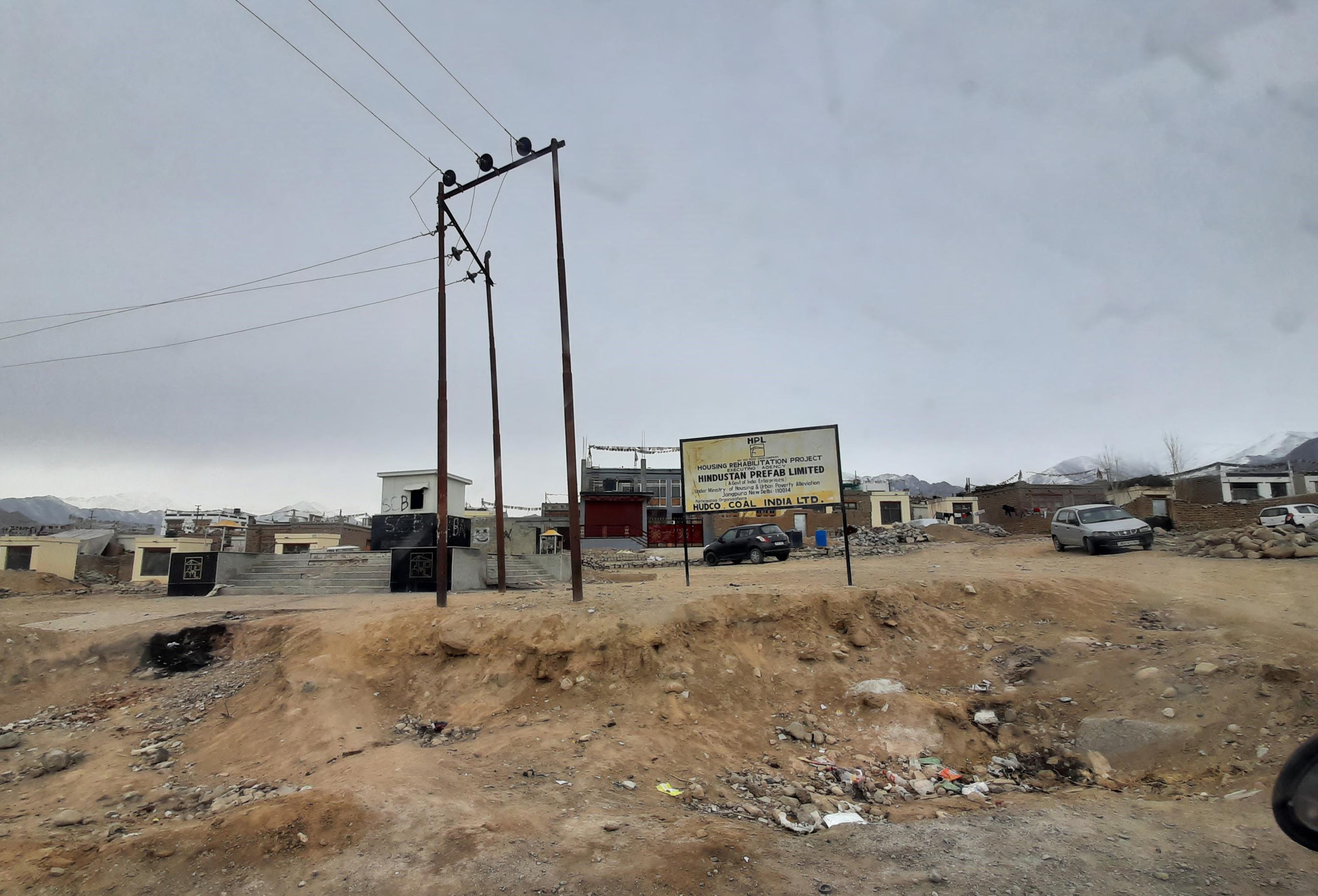
5.3 Solar Colony Choglamsar, Ladakh Hindustan Prefab Ltd.
Figure 77: Site for neighbourhood park Source: Author
35
Figure 79: Foundation blocks Source: Author
Figure 80: Standalone module Source: Author
3.1.2. MODULE: a) Walls: The module is a cuboid made out of 2 layers of hard PVC with insulation in between on all walls, floor, and roof. It has a base of 3.5m x 4m and a height of 3m. The thickness of the PVC panel is 0.25” and the thickness of the foam insulation in 2”, making the whole wall 2.5” thick. Figure 78: Row of modules Source: hindprefab.org
The solar colony was planned after the 2010 cloudburst and flood in Leh and neighbouring villages of Ladakh. Several families’ homes were destroyed by the flash-flood and were rehabilitated in the solar colony where Prefab one room houses have been constructed by HPL for the affected people of the region. The one room module along with a small piece of land of 165sqm were allotted to each displaced family who were allowed to build and expand their houses through their own resources over time.
b) Openings: It has a door on one façade and a window on the adjacent one. The door is made of insulated PVC panels whereas the windows are aluminium casement windows with single layered glass. The fixing of these windows to the module are not properly done in most of the modules, leaving air gaps which lead to leakage of the hot air that is inside and allows the cold air from outside. Due to this issue, most of the tenants have to cover the window with plastic sheets in winters to provide an extra layer of insulation.
3.1. STRUCTURE: 3.1.1. FOUNDATION: The foundation is created by erecting 9 blocks of RCC on which 3 I-girders are placed on which the floor of the module rests to raise the entire module off the ground. The foundation blocks are 2’x2’ raised to a height of 2’ from the ground. 36
Figure 81: Inside of a module Source: Author
Figure 82: Frost formation on window Source: Author
c) Roof: The PVC insulated roof provides enough insulation but does not absorb the moisture inside the room that is generated by a traditional heater(bukhari) like the traditional roof in which the mud and hay absorb the moisture. This moisture condenses on the roof and freezes or drips down on the floor and freezes in winters. To counter this, tenants have stopped using Bukhari and use modern electric heaters which consume a ton of electricity and are not energy efficient for such type of climate.
Figure 85: Module attached to mud brick, timber structure Source: Author
Figure 86: Attachment from inside the house Source: Author
3.2. SERVICES:
Figure 83: Water condensing on the roof Source: Author
Figure 84: Water dropping down and freezing. Source: Author
d) Expansion: The module may be attached to a typical brick, timber or brick, RCC. Structure as per the requirements of the tenant family. The family was provided 165sqm. of land on which they may build with their own material and resources. A standard layout plan was provided to the tenants following which they can expand the module to 1/2/3 bhk house. Since the allotment of plots, almost everyone has expanded their homes and some have even removed the module due to its inefficiency in winters to create more room on their plot for construction.
a) Toilets: One combined WC, bath is built outside each house in their plots. The use of traditional dry toilets has been prohibited by the Municipal Corporation due to the problem of foul smell to the neighbouring houses. In summers these flush-toilets function normally but in winters, they stop functioning as the water supply through pipes stop as the water freezes inside the pipes because they are not insulated. Due to this issue, a lot of tenants resort to defecating in the open as there are no functioning public toilets in the area too.
Figure 87: Toilet block on the right of the module Source: Author
37
b) Water supply: Summers- PHE maintained water supply pipelines deliver water to public taps on each street which function from 8am-10am in the morning and 4pm-6pm in the evening. Winters- MC supplies water through water tanks that refill the private water tanks at home once in every 3 days.
3.3. SITE:
c) Electricity: Summers- The NHPC hydro-power plant at Nimu generates and supplies electricity to the entire region. Winters- The NHPC hydro-power plant generates significantly lesser electricity as all the rivers freeze and this area is not yet connected to the Northern grid like Leh city which provides electricity in case of shortage. Therefore, this area experiences 6-8 hours of power outage every day.
a) Site Planning: The plots were oriented towards South or South-East to maximum capture of solar radiation in the morning and evenings but due to improper planning of fenestration on the module, the windows in a lot of houses are not facing South and do not allow any sunlight in at all.
d) Sewage: Septic tanks and soak pits at every plot which is emptied by the MC and taken to the FSTP near Bomgard, Leh. e) Garbage disposal: Door to door truck collection service by the MC which takes the waste to either the Waste disposal site at Bomgard, Leh or the Solid Waste Management plant near Skampari.
The complete proposal is for 1281 housing units spread across 11 neighourhoods called ‘mohollas’. From these 11 mohallas, currently only mohalla 1,2, and 11 have been allotted whereas the rest of the area was kept for future expansion.
After the expansion of most of the houses without any defined setbacks, most of the houses are so close together that they shade each other and do not allow any house to absorb the required amount of solar radiation. b) Connectivity: Choglamsar is the nearest town outside of Leh city and is very well connected through bus transit to all the neighbouring towns which are located on the Leh-Manali highway. Buses come at the interval of every 15 minutes from 8am to 8pm. Nearest bus stop is at the Choglamsar main market junction. Buses connect to Leh, Shey, Thicksey, Matho, Chushoth, Sabu, Marsala, and Sakthi. There is no other means of public transport. There is no last mile transit system. b) Social Infrastructure: Proposed infrastructure for the colony- 2 Primary Schools, 1 Nursery School, Club, Medical Dispensary, Nursery School, Police Station, 6 small area parks, 2 large neighbourhood parks, plots reserved for commercial, institutional and religious functions. Existing infrastructure- The PWD was responsible for development of site roads, housing blocks but due to shortage of funds did not build
38
Figure 88: Solar Colony, Choglamsar- complete proposal Source: Author
39
Figure 89: Solar Colony, Choglamsar- existing satellite image Source: Google maps
any other infrastructure that was proposed and PWD officials are now looking for other government organizations to step in and build this infrastructure. Therefore, currently all social infrastructure to support the colony is in the neighbouring unplanned colony or near the Choglamsar main market at the Leh-Manali highway. The nearest school is in the unplanned housing colony West of mohalla 11. The central Institute of Budhhist studies is just South of mohalla 8. Nearest police station is near the Choglamsar main market. Nearest monastery is 500m South of the Mohalla 7. 40
There are small neighbourhood shops spread out across the unplanned colony and residents need to go to the Chogalmsar main market, 800m West of mohalla 11 for all other needs. c) Physical Infrastructure: Proposed infrastructure for the colony- Waste management plant, Petrol pump, Renewable energy centre, Warehouse, Electrical substation. Existing infrastructure- Explained under the 3.2. Services heading.
Case Example
5.4 House of Families Nuuk, Greenland Fantastic Norway
Figure 90: 3D render, House of Families Source: Archdaily.com
41
This is a project for the Greenland Self Government to provide housing for disadvantaged young women with children in Nuuk, Greenland. The building has been designed to be inviting and protective by the architects to create a safe and nurturing environment for the young women and their children. The house is broken into smaller building volumes to create the conceptual form of an assembly of many small houses that come together to create the larger structure. 4.1. STRUCTURE: The blocks are made using timer frame structure with plywood panels with an insulation cavity in the middle. The plywood panels on the outer sides are 0.5” thick with the insulation in the middle being 3.5” thick to withstand the cold and harsh climate of Greenland, and on the interiors is 0.5” drywall. 4.1.1. PASSIVE SOLAR TECHNIQUES: The building creates a literal shelter from the rough climatic conditions of the region. A heavy building mass is dense and closed to the north. Outdoor spaces are oriented to the south, but protected from heavy wind and rain in the southwest. The building mass breaks up and allows light to enter the front of the building where vegetation can flourish. The building also applies environmental technologies to sustain the life inside: an external heating system, passive solar technology, solar panels and water heating all contribute to a technological management system that regulates and controls energy consumption. (Irina Vinnitskaya, 2010)
Figure 91: Section of a typical block Source: Archdaily.com
42
This is a social housing project established to create an environment of learning and development for both the mothers and their children. It is an environment where the families can learn to live on their own, fend for themselves, and eventually live an independent life. All functions except a single bedroom and toilet per family are shared by at least 2 or more groups staying in the block. This creates a sense of communal living in a very small scale. The conceptual backbone of the programmatic functions of the whole assembly is a range of social zones and meeting places where various functions come together and various encounters can take place. The common functions within the building: the kitchens, the playgrounds, the sitting rooms all establish social relationships to reintroduce the residents back into society. (Irina Vinnitskaya, 2010)
Figure 92: Site Plan. House of Families Source: Archdaily.com
43
Case Example
5.5 Zero Energy Demonstration Home Denver, USA HFHMD, NREL
Figure 93: Zero Energy Demonstration Home Source: Amy Glickson, NREL
44
In 2004, HFHMD (Habitat for Humanity (Habitat for Humanity of Metro Denver) partnered with NREL (National Renewable Energy Laboratory for a third time to design and build a demonstration home. This time, however, the partners set out to build a zero energy home. It would be designed to produce as much energy as it consumed over the course of a year. To meet this goal, the design would include attributes such as building envelope efficiency; passive and active solar features; and efficient equipment, appliances, and lighting.
The structure’s is made completely out of timber with double stud walls with a gap of 9.5” in the middle for insulation. On the interior of the stud framing, gypsum board or fibre board is used whereas on the external side of the wall, fibre board is stuck to the framing on top of which comes the air and waterproofing layer, over which comes the cladding or fibre cement lap siding.
The 1,280-sq.-ft., three-bedroom home was completed in September 2005. Once built, NREL researchers monitored the home’s energy production and use, and found that the home actually produced 24% more energy than it consumed over the course of a year, on a source energy basis. Figure 95: These raised trusses at the intersection of the wall and roof frames allowed for 2 feet of insulation to be blown into the attic.
5.1. STRUCTURE: From the beginning of the design process, NREL building researchers and HFHMD staff and volunteers worked closely to find a balance between engineering ideals and practicality. The combined perspectives led to a design that balances ease of construction and low cost while still meeting the zero energy goal.
Figure 94: The home’s shell consists of two exterior walls, insulated both between the studs of each wall and in the space between each wall, providing superior heat retention. Source: Paul Norton
Source: Paul Norton
5.1.1. PASSIVE SOLAR TECHNIQUES: Insulation This demonstration home was “super-insulated” with R-40 fiberglass batt insulation in the walls, R-60 insulation in the attic, and R-30 insulation in the floor. The roof required raised heel trusses to allow room for 2 feet of blown-in insulation in the attic. The house exterior actually has two walls — an outer 2-in. x 4-in. structural stud wall and, 3½ in. inside that, a second 2-in. x 4-in. stud wall. Fiberglass batts were placed within and between these walls. This super-insulated shell greatly reduces the demand for heat. Maximizing solar radiation capture & Minimizing heat loss Most windows were located on the long south side of the home, and fewer windows were placed on the north, east, and west sides. The roof was designed to have 3-ft. overhangs, which shade the window 45
in the summer and allow sunlight to enter the windows in the winter. The windows themselves are double-glazed, low-emissivity models. This means they have been coated to reduce radiant heat transfer, which increases the windows’ insulating value. 5.1.2. ACTIVE SPACE HEATING & VENTILATION: Space Heating The space heating system combines a direct vent natural gas furnace in the living/dining area and small baseboard electric resistive heaters in the three bedrooms. Because each heating appliance has its own thermostat, each zone can be warmed as needed. Mechanical Ventilation Because the house leaks very little air, it requires a mechanical ventilation system to provide fresh air while minimizing energy losses. A balanced energy recovery ventilation system supplies fresh air to the living room and bedrooms and exhausts air from the kitchen and bathroom. The warmth of the exhaust air is used to heat the incoming fresh air. 5.1.3. ACHIEVING HIGH ENERGY EFFICIENCY: Solar and Natural Gas Water Heating NREL’s building engineers specified a solar water heating system with a 96-sq.-ft., roof-mounted solar collector with a 200-gal. water storage tank. The water thermostat is set to maintain the temperature of the water at 115°F. If necessary, a backup natural gas tank-less water heater helps maintain the temperature. The tank-less system uses no heating energy when the solar water system is able to maintain the temperature. Appliances and Lighting The electrical load was reduced by using ENERGY STAR appliances and using compact fluorescent lights throughout the home. Solar Panel Electric System Once all energy loads were reduced during the design process, a 46
photovoltaic (PV) system was sized to meet the remaining electrical needs and offset natural gas use. The 4-kilowatt solar PV system is gridconnected with no battery backup. The system feeds electricity into the utility grid when it produces more electricity than the home needs, and it consumes electricity from the grid when the home needs more electricity than the PV system produces.
47
CASE STUDIES COMPARISON MATRIX
6. SITE ANANLYIS Cheetah Chowk, Leh
48
Residential & Non-residential Land Use Leh, Ladakh
Land Use in and around the Site Residential Social Infrastructure Commercial
49
EVOLUTION OF SOUTH LEH
50
CONNECTIVITY
ARTERIAL ROADS
COLLECTOR ROADS
BUS STOP
SUB-ARTERIAL ROADS
LOCAL ROADS
TAXI STAND
20m WIDE 16m WIDE
10m WIDE 6m WIDE
BUSES TO NEAREST TOWN- CHOGLAMSAR CABS FOR ALL NEEDS
51
SOCIAL INFRASTRUCTURE
Educational Institutes
52
Government Offices
Hospitals
53
54 KEY PLAN FOR SITE PHOTOGRAPHS
SITE PHOTOGRAPHS
From the highway to the south-west entrance of the site. Maximum traffic approaches from this route.
Southern edge of the site. Unused public area, must be activated.
Existing central park. Important node for public activities. Usually occupied by children
Road connecting northern edge of site to the central park.
55
SITE PHOTOGRAPHS 56
Internal roads in site covered with hard, slippery snow. Hazardous in winters.
Backyard on the left with dry toilet inside the steel structure; Building on the right has its windows broken and covered with plastic sheets.
Road leading to northern entrance of the site; One of the buildings in severly bad condition.
Road leading to Post office quarters which has an access through the site.
SITE PHOTOGRAPHS
Road along eastern edge of site. Edge opposite to site is lined with shops. Commercial destination for everyone living in this area.
Central road coming from unplanned housing colony to the site. Is mostly active with pedestrians and traffic.
Government offices near the site where most of the govt. quarters residents will be working,
Government offices in foreground and view towards the South.
57
7. TECHNOLOGICAL DRIVERS
58
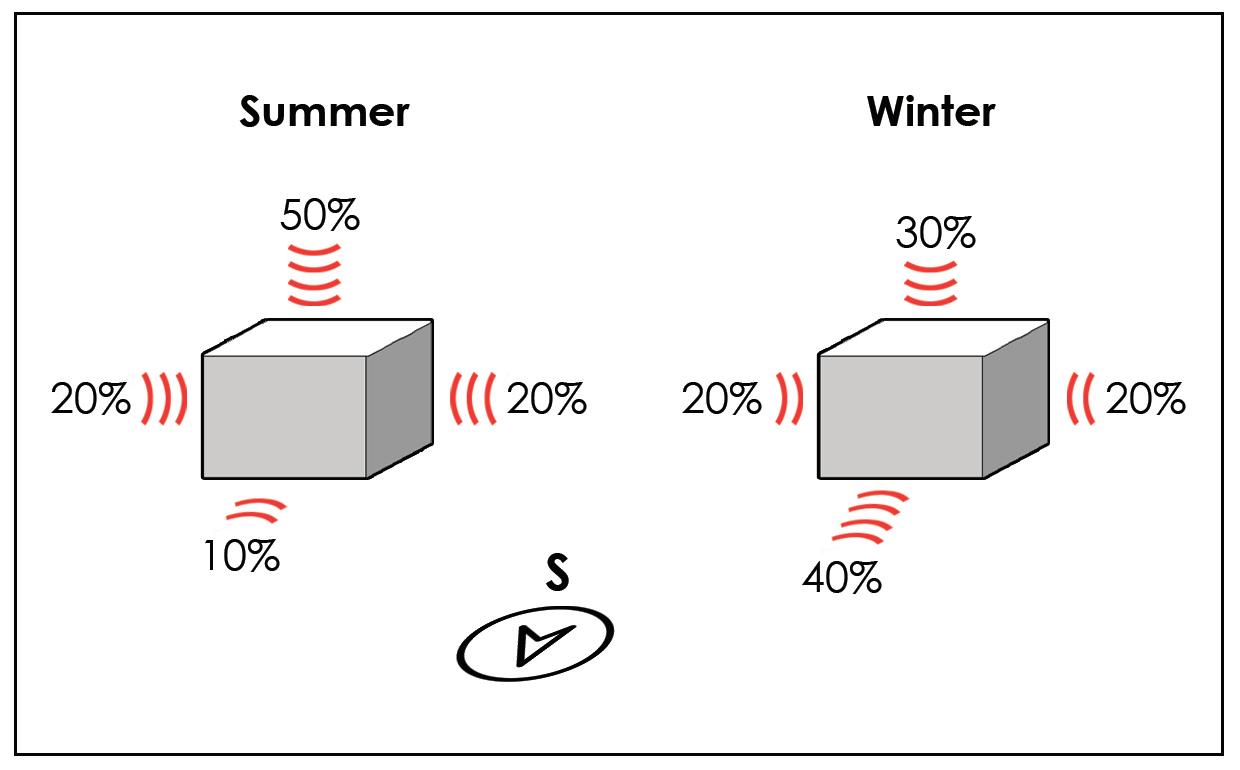
7.1. Structure 1.1) Passive Solar Building Concept: There are five inter-related components of PSB which make the building energy efficienta. Collection and absorption of solar radiation during the day; b. Storage of heat collected from solar radiation during the day; c. Release of this heat into the interior of the building during the night; d. Insulation of the building to prevent heat loss; e. Ventilation to supply fresh air to inhabitants. 1.2) Orientation: The most important concept of PSB design is maximizing heat gain through solar radiations during the daytime in winters. At the same time, collecting too much radiation during summers may result in overheating. The south face has the highest potential for solar radiation collection in the winters (40%) whereas in summers the roof has the highest solar radiation collection and the south face has the least (10%) among all the sides. So the best option is to orient the longest side of the building towards South to collect maximum sun energy in the winters. The orientation can further be adjusted according to the building’s function. If the building is in use during daytime, the South facade can be tilted 10° towards East; If the building is in use during night time, the South facade can be tilted 10° towards West; If the building is in use at both day time and night time, the best orientation is towards perfect South. 1.3) Site Selection: In the winters, almost 90% of the solar radiation reaching the South facade can be collected between 9 am and 3 pm, therefore it is essential that unobstructed sun radiation reach the
Figure 96: Percentage of Sun-Radiation recieved by each face of the building in Ladakh region Source: Author
building during this period. There are two types of obstructions: - Distant obstruction: Mountains or clouds; - Near obstructions: Surrounding trees or other buildings. The distance of nearby obstructions shall be at least twice the height of the obstruction so that solar radiation may reach the building uninterrupted. For example, if there is a single-storeyed building towards the south of the target building, there should at least be a clear distance of 20ft between the two structures. In case the buildings are too close and there is no other alternative, we can provide a skylight on the roof as the solar gains from the South facade are very limited.
Figure 97: Distant Obstructions Source: Author
Figure 98: Nearby Obstructions Source: GERES India Design Manual 2012
59
1.4) Room layout: - Rooms that require heating are located along the South facade. - Rooms that require heating early in the day should be located in the Southeast. - Rooms which are not used in the day but require heating should be in the Southwest. - Rooms that do not require heating shall be on the north side to create a buffer zone to reduce heat loss. - At the entrance, an airlock should be provided to reduce cold air infiltration. - The entrance should not be in the direction of the wind or on the South facade. 1.5) Building Shape: The shape of the building should be such that it provides the required volume while having the least amount of external surface area possible. More the external surface area more is the heat loss through those surfaces. The lower the surface area to volume ratio of the building, lower is the effective heat loss. Assume the length of the room to be along the South face and the width to be perpendicular to it, the volume of a room should be limited in such a way that it can warm up in sufficient time and passive solar techniques can be implemented in this room. The width of the room should be limited to 14ft and the height should be limited to 8.5ft, whereas the length of the room can be as much as we like.
Figure 99: Optimal surface to volume ratio Source: GERES India Design Manual 2012
60
1.6) Fenestration and Shading: - South facade should have large windows to maximize the solar energy gain during winters. To reduce the risk of overheating in summers, horizontal overhangs shall be provided over the openings on South side. - East and West facades should have limited sized windows to reduce heat loss. Although these sides are reached by solar radiations, the heat loss at night is much more than the heat gains at the day through these sides. Solar radiations may also create overheating at the time of sunrise and sunset in the summers, therefore we need to provide vertical shading devices on these facades or plant deciduous trees outside which provide shade during summers and shed their leaves to allow solar gains in the winters. - The North side is never reached by direct solar radiation, so we should avoid or put very limited sized windows on this facade to minimize the heat loss as much as possible. 1.7) Mechanism of Heat Transfer: There are three mechanisms of heat transfer. - Convection: When a moving fluid comes in contact with a surface of higher energy (warmer), it exchanges calorific energy with the surface and gets warmed up. The amount of heat transmitted is proportional to the difference of temperature between the fluid and the solid. Convection may happen within the same fluid when there is a temperature difference within it. Convection can also be forced, for example by the use of a Trombe wall which is used to store solar radiation such that the cold air present in the room passes through the cavity in the wall to get warmed up and then goes back into the room. The working of a Trombe wall will
be explained in detail later. - Conduction: The transfer of heat within a solid or a fluid due to the vibration of the molecule with higher energy to the molecule with lower
climate is immensely cold during winters, thermal insulation is of utmost importance. The insulation should be implemented on the roof, walls, windows, and floor.
energy through collision is called conduction. Conduction occurs from the hotter part towards the colder part of the solid/ fluid. When the sun rays fall on an external wall of the wall, the molecules on the exterior side absorb the energy and vibrate and collide to pass it on the colder interior part of the wall. - Radiation: The transfer of heat by electromagnetic waves i.e. without the contact of materials. The sun’s heat reaches the building through solar radiation. In case of an opaque object, for example a wall, it absorbs most of the solar radiation and reflects some back. The absorbed radiation is stored in the wall which is released during the night time into the interior of the building. In the case of transparent materials such as glass, most of the radiation is transmitted through the glass into the room while some of it is reflected back and only a minute part is absorbed.
Thermal mass is a material which can store a high quantity of energy and also takes a higher time to cool off. Such materials should be implemented on the South facade to gain heat during the daytime and release it to the interior at night. There can be four cases for wall insulation: a. Wall without insulation: This wall will store energy during the day but will release most of it towards the outside at night time. It is not an efficient thermal mass nor does it provide enough insulation. b. Wall with inner insulation: Although the wall will collect energy during daytime, all of it will quickly be lost during night time since there is no way for the thermal mass to radiate the energy towards the interior of the building. It is not an efficient thermal mass but it does provide enough insulation. c. Wall with insulation in the middle or double wall: During the day, the wall collect the solar energy and during the night most of the heat released is towards the interior of the building thanks to the layer of insulation preventing heat transfer towards the outside. It is an efficient thermal mass and provides enough insulation. d. Thick wall with thin outer insulation: Energy is stored in the thick wall during daytime and is mostly released towards the interiors at night time. This type of system is suitable in regions where summers are warm but in Leh, this type of insulation is not enough for the harsh winters. It is an
Source: GERES India Design Manual 2012
1.8) Thermal Insulation and Thermal Mass: Materials with lower thermal conductivity are said to be good insulators. These type of materials allow less heat transfer through conduction, therefore is used in building construction to prevent heat loss from the inside of the building during night time. In the case of Leh, where the
efficient thermal mass but does not provide enough insulation.
61
7.3. Sustainability
Wall without insulation
Wall with inner insulation
Wall with insulation in middle
Wall with outer insulation
3.1) Compressed Stabilized Earth Blocks (Auroville Earth Institute) The first attempts to create compressed earth blocks were made in the year 1803 when architect Francois Cointereaux used hand rammers to compress earth into a small wooden mould held with the feet. Auram press 3000 which has 18 types of moulds and can produce about 70 different types of blocks. Most of the times stabilizers such as cement or lime are added to these blocks, hence the name Compressed Stabilized Earth Blocks. As of now, very few people in Leh know of this alternative and are using it since the market and industry is adapted to materials like concrete but LEDeG is producing and marketing CSEB at the Rural Building Centre at Choglamsar.
Figure 100: Thermal Insulations Source: Author
1.2) Cost Effective Construction Tecnologies: a. Material and Logistics cost reduction b. Labour cost reduction c. Alternate construction techniques d. Reduction in running cost
7.2. Services
1. Soil Identification: A suitable soil for CSEB should have the following proportions15% Gravel + 50% Sand + 15% Silt + 20% Clay. If any one of these components of soil is more than the required amount, the soil will be suitably called gravely, sandy, silty or clayey. These proportions were also observed by me while doing soil testing for a rammed earth workshop conducted by LEDeG.
2.1) HVAC 2.2) Electrical supply 2.3) Water supply and drainage 2.4) Sewage collection and treatment
2. Soil Stabilization: There are several stabilizers like chemicals, resins or natural products but the most commonly used ones are cement and lime. The selection of stabilizer and its quantity depends upon the soil quality. If the soil is sandy, cement is preferred as a stabilizer to achieve
2.5) Garbage/ Waste collection and treatment 2.6) Energy generation 2.7) Active Space heating 2.8) Grey-water reuse
higher strength quickly but if the soil is more clayey, lime is the preferred stabilizer which takes a longer time to achieve good strength. The proportion of stabilizer are as follows- Cement: 3% (min); 5% (avg); No
62
maximum limit; Lime: 2% (min); 6% (avg); 10% (max).
- Untrained teams produce bad quality blocks; - Over-stabilization resulting in extensive costs; - Under-stabilization resulting in poor quality;
3. Energy Effectiveness: The pollution emission (Kg of CO2/m2)in the making of CSEB as stated by Auroville Earth Institute is 2.4 times less than factory made wire cut bricks and 7.9 times less than country fired bricks. The energy consumed (MJ) in its production is 4.9 times less than wire cut bricks and 15.1 times less than fired bricks.
- Low social acceptance as earth is considered to be weaker than concrete in Leh.
4. Advantages of CSEB: - Locally available on site, hence zero transportation cost; - Bio-degradable material: If a building is destroyed, the soil cement mix will be destroyed in around 10 to 20 years and all the soil will return to its origin; - Job creation: It is a simple technology that can be easily taught to unskilled labours; - Cheaper: Although the cost depends on local material and equipment, CSEB will mostly be cheaper than fired or wire-cut bricks; - Reducing imports: No need to import any materials from far away, saving cost and preventing the pollution that would have happened to transport materials using trucks; - Flexible production scale: CSEB equipment are available from smallscale manual press to large-scale motorizes press; - Energy-efficient and eco friendly; - Cost-effective 5. Limitations of CSEB: - Proper soil identification required; - High-rise buildings are difficult to do;
3.2) GluLam Beams Large structural members are produced by joining together many smaller strips of wood together with glue to form glue-laminated wood (glulam for short). Individual laminations are most commonly 1.5” in depth. COMMON DIMENSIONS FOR RESIDENTIAL CONSTRUCTION: Width: 3.5” - 6.75” Depth: 9” - 36” Depth can be calculated as: d=span/15 That is when the distance between 2 beams is 5m. Reducing the spacing between 2 beams can effectively reduce the beam depth as well. ADVANTAGES: • Desirable size: Beams of any size can be fabricated with smaller sections of wood which is not possible in solid timber sections for which you need to search for a tree of sufficient girth and height. • Desirable shape: Wood can be laminated into shapes that cannot be obtained in nature: curves, angles, and varied cross sections. 63
• Desirable quality: Quality can be specified and closely controlled by cutting out defects in laminated members. The strongest, highest-quality wood can be placed
DISADVANTAGES: • Fabrication cost is higher than solid timber beams. • Fabrication time is spent which is not the case in solid timber sections.
in the parts of the beam where the structural stresses are the highest i.e. the top and bottom.
• Skilled labour required for fabrication.
Figure 101: GluLam Beam, Shapes & Quality Source: Author
• Higher strength: By fabricating hybrid glulam beams as shown in the figure above, we can get beams that are 20% stronger and 15% stiffer which means we require beams of lesser depth. This results in savings of 25-40% volume of wood.
GLULAM LAMINATING PROCESS: 1. Drying: Feedstock can be air-dried or artificially dried to reduce the moisture content to between 8%-16% as suggested by adhesive producer. 2. Strength grading: Air-dried timber are sent for strength grading. Grading can be done by means of non-destructive tools such as machine stress grader, natural frequency tools, or in our case we will try visual grading 3. Jointing: Undesirable defects are visually identified and cut out of the timber. These shorter length ‘defect free’ timbers known as shooks are conveyed to the joint profiling line. There are 2 types of joints: Finger joint and Scarf joint. We will use scarf joints for our purpose. 4. Planing: Scarf jointed timbers are sent for planing to improve surface
Figure 102: Scarf Joint (left) & Finger Joint (right) Source: Author
64
smoothness and uniformity of dimension. This is to facilitate lamination and improve wood-adhesive bonding. 5. Glue spreading: Appropriate adhesive mix is produced and applied on the surface of the scarf jointed timbers. Freshly planed wood surface would make and stronger glue joints and only minimum time should the timber be exposed between the planing, glue spreading and lamination process so as to minimize surface contamination, occurrence of raised grain, warping or cupping. 6. Layout of laminates: End points are points of weakness. The use of greater number of end-joints in laminates will introduce more points of weakness. During layering of the laminates, the end joints should not fall in line to the adjacent end joints to ensure uniform distribution of stresses. 7. Clamping: After glue spreading, the laminations are transferred to the
Figure 103: Joints in Lamination (Scarf Joint) Source: Author
cramping or clamping station. The lamellae of the glulam member are clenched using clamp jigs screws and bolts. The type of cramping bed depends on whether the glulam member is curved or straight. 8. Post curing: The bonded members are left for curing for several days depending on the requirement of the type of adhesive. 9. Finishing: Trimming of excessive adhesives and cut to required sizes.
Figure 104: GluLam Manufacturing Process Source: Author
3.3) Timber Frame Construction The term ‘timber frame’ typically describes a system of panelised structural walls and floors constructed from small section timber beams and columns, clad with board products, in which the timber frame transmits vertical and horizontal loads to the foundations. Timber frames can be the most suitable choice if the structural shell is required quickly, if the ground conditions are particularly poor, or if the design does not include very large structural spans. When considering a timber frame building, the following advantages and disadvantages should be borne in mind. 65
DISADVANTAGES: • Capillary movement of water between wooden members may lead to warping and rotting. • Wood will eventually rot and needs good maintenance. • Poor acoustic insulation as compared to brick wall. • Wood boring insects like termites need to be prevented and may cause major structural issues if ignored.
Figure 105: External wall section of timber frame construction Source: www.ursa-uk.co.uk
ADVANTAGES: • Incredibly quick construction time, increasing the construction efficiency by reducing the duration, labour and resources required. • The structural members and panelling can be produced in factory/ workshop conditions ensuring higher quality of building materials. • The versatility of the techniques allows for greater freedom in design in the form as well as the materials used. • It works well for prefabrication and mass-production. • Its very environment friendly and cuts down the carbon footprint if all materials are locally sourced. Wood is an ecologically friendly and renewable material. • Wood is a highly efficient insulator. • Its a dry form of construction, which means it not only reduces the amount of water used significantly as compared to RCC. frame construction but also cuts out the curing and drying time completely. 66
3.4) Poured Earth panelling In order to be used as panelling for the timber frame structure, we need to use a material that can be locally sourced in order to keep the carbon footprint as low as possible. One such material is Earth which has been traditionally used in Ladakh for centuries and is versatile enough to be used as concrete to make panels. a. Preparation: Poured earth is similar to ordinary concrete, in that it is mixed and formed like concrete and uses Portland cement as a binder. The main difference is that instead of the sand/gravel used as an aggregate in concrete, poured earth uses ordinary soil and generally uses less Portland cement. Poured earth could be considered a “moderate strength concrete”. Since poured earth is similar to concrete, local suppliers can provide the product which can then be pumped using traditional concrete pump trucks. Standard concrete forms can be used in preparation for the pour. b. Maintenance: Little to no maintenance is required of poured earth walls, since they have a high resistance to the deteriorating effects of water and sun. c. Insulation & Thermal Mass: It is possible to incorporate rigid insulation within a poured earth wall, so that there is a thermal break between the exterior and the interior, thus allowing the interior portion of the wall to serve as appropriate thermal
mass for the building. d. Cost of Construction: Generally, poured earth walls increase the overall cost of construction by 10% - 20%, mainly because of the custom nature of the process. When more homes are built, then the economy of scale should make this method competitive with traditional building.
A new system of construction: Since poured earth panelling will be much heavier than standard plasterboard or plyboard panelling used in drywall construction, we would require structural members that can take higher amount of loads, for example, the Glulam beams mentioned earlier. By combining timber frame structure with glulam timber and poured earth, we can achieve the following: a. Effectively reduce the carbon footprint of construction, resulting in higher energy efficiency; b. Reduce the construction duration by mechanisation and prefabrication to directly reduce the labour and utilities cost; c. Reduce the amount of water used for construction which is a valuable resource in a cold desert like Ladakh; d. Rely less on manpower as most of the process can be mechanised. e. Achieve better insulation and higher thermal mass than typical RCC., brick construction.
Figure 106: Timber frame structural system combining
GluLam load bearing members with traditional roofing system. Source: Author
67
68
Figure 107: External wall section showing poured earth panels on timber frame cavity wall.
Figure 108: External wall section showing active solar space heating technology.
Source: Author
Source: Author
8. VISION KEY ISSUES TO BE ADDRESSED 1. Decline of Agriculture
2. Large scale projects take too much time
Since the last 2 decades, more and more Ladakhi’s have been showing interest in higher studies after high school. As a result, more job oppurtunities are opening up for these people in the secondary and tertiary sector.
The construction season in Leh. Ladakh is only 4-5 months each year. Imagine a project taking some X amount of years to complete, in Leh, the same project would take 2X years with same or lesser quality and strength.
After the boom in tourism in the previous decade, many Ladakhi’s have also opened up hotels on agricultural land as administration cannot keep a proper check on development.
After an optimal amount of time for construction passes, the time taken for construction is directly proportionate to the project cost as the services and labour cost shoots up with passing time.
The reduce in agriculture is covered by food and vegetables transported in from other states and distributed at a subsidized rate, but only in Summers. In Winters, there is no proper supply of fresh food and vegetables as the crops grown in the region are unsatisfactory for the amount of population. The food is often shipped through air cargo but it shoots up the costs exponentially.
Another issue is improper storage of construction materials. Locals store concrete bags at the end of summer to use it in the next season before the roads open up. Little do they know that till the time comes, the concrete has alreaady gone bad. This results in buildings with more impurities, lesser overall strength.
69
3. Concrete is not suitable for Leh
4. Nobody wants to stay in Winters
Currently, RCC. is one of the primary building material in most of the
Most of the higher middle and upper class Ladakhi’s have a second
projects in Leh. RCC. grew popular among locals after the boom in tourism as there was a huge population influx and for accommodating these tourists, the city needed a lot more hotels, and residences and concrete provides that speed to the process.
Winter home down south from Leh. Almost half of the local population migrates from Leh to either vacation homes in other regions or their respective villages in Ladakh.
The construction industry is relying on concrete too much, specially for a cold climate like Leh. Concrete is highly conductive and requires heavy insulation to retain the heat in Winters. Most of the hotels and homes built with RCC. need artificial heating in Winters. Concrete is not reusable or biodegradable. The lifespan of a concrete building is approximately 100 years maximum, after which it starts to deteriorate. Once the building is structurally unstable and it taken down, it gives nothing but debris. There are very few components that may be reused or recycled. Cost of concrete is too high in Leh as there are no industries for the production of concrete and it has to be shipped in from other states.
1. Unsuitable for extreme cold 2. Higher cost 3. Non-reusable
70
Snowfall is reducing each year as a result of climate change and the the weather becomes extremely cold and dry. Such harsh situations are uninhabitable for most. This is a huge problem for specially Govt. employees who are obligated to stay throughout Winters whereas their families leave them alone.
Solution: There is a need of a Winter habitable living space which encourages people to not stay indoors during cold but to go out and comfortably enjoy communal activities throughout the year. Additionally, the project should be constructed with the minimum expense possible to act as a reference for all future CPWD projects in the UT of Ladakh. To accomplish this, we may need to come up with new and innovative construction technologies which not only speed up the process but also relies less on the expertise of the labour.
9. DESIGN DEVELOPMENT 1st Draft:
The design journey started with me going with the easiest approach, which was to make two types of blocks; one with type 1 & 2 houses and one with type 3 & 4 houses. These blocks were meant to resemble a traditional Ladakhi house with a central public terrace which may be
bedrooms, whereas the kitchen, dining and store could be towards the North side. The site planning was done according to the basic theories of neighbourhood planning where there’s no through road for vehicles
used as a greenhouse during winters to warm up the adjacent blocks and also terrace farming. The indoor layout of the houses however, was still very western which we are familiar with. The main aim while figuring out the zoning was to keep all the living areas of the house towards the South i.e. the living and
to cross the site so that only the residents enter the inner roads, the commercial services were kept at the edges and the public areas like parks were at the centre so as to be easily reachable to all. The blocks were equally distanced so that they don’t block each other’s sun and the higher rated blocks were at the south side with a better view. 71
2nd Draft:
3rd Draft:
The first draft of the site plan was too basic and wasn’t creating any interesting communal spaces which are a necessity, plus all the blocks were too scattered and we required a more compact design.
high carbon footprint; Also, it was too inorganic which is not a feature of traditional settlements in Ladakh. So I moved on to try massing which curves along the contours of the
I decided to try a hexagonal grid where massing woth be placed on 4 of the 6 sides of each hexagon such that no block’s sun is blocked but this setup would require too much of cutting and filling which means a
site. Row housing was preferred over clusters because in row housing every house recieves sunlight equally with blockage. The roads were kept to the edges and the centre was completely pedestrianized.
72
3rd Draft: This draft was further developed keeping the indoor layouts similar as before. The valley cutting through the site from North to South-east was turned into green zone or parking with would help in mitigation against flash floods if we line both side of the valley with trees, the water would flow through the valley towards the open area at further South without damaging the buildings. Social infrastructure was added such as labrary, art gallery, and a sports club. The problem with row housing would be that it divided the site into long public zones with low visual connectivity. So I decided to rise the row housing of type 1&2 higher supprted by stilts with cores at proper intervals and clusters of type 3&4 at nodes as shown in the sections on the right. This established physical connectivity but visual connectivity was still low, plus we had unused space under the stilts. 73
4th Draft:
The row housing units’ layouts were evolved into a more traditional Ladakhi style with an open kitchen combined with living/dining and a separate sun-room. Units were removved at certain public nodes to create more visual connectivity but it still wasn’t enough. Also, the access to the row housing was a corridor right in front of the living areas of the houses which created a huge privacy issue. Furthermore, there were still no smaller scale communal areas. 74
5th Draft:
The site planning clearly required clusters to form smaller scale public areas within them. A cluster was formed as shown in the top-left diagram such that it creates a neighbourhood spacce in the centre while
The valley still had the larger open areas flowing into the smaller neighbourhood streets. Parking was broken up into smaller parts to reach closer to all blocks and pedestrians street were widened to be used
still maintaining the blocks’ orientation within a 30° range from true South. The placement of these clusters was along the contours to minimize the cut and fill while maintaining a proper distance.
in case or fire or medical emergencies to reach all cores. House layout was kept similar while increasing the efficiency by reducing the number of cores and circulation area. 75
10. FINAL DESIGN
SITE PLAN 76
SITE SECTIONS
77
SITE AERIAL VIEW
78
CLUSTER - 1
79
CLUSTER - 2
80
1
Block 1 - Axonometric 81
5 S25
6020
2
4
S25
S25
3000
LIFT (1800 x 1800)
8480
2040
1 S25
1000
2060
2040
1980
UP W3
D2
CORE D2
W3
W3
TOILET (1300 x 2150)
W3
D1
AIRLOCK
1900
W2
7580
9180
KITCHEN (2550 x 2800)
D3 D1
W3
D2
W3 D2
TOILE T (1300 x 2150)
D3
W2
240
D3
LIVING/SUNROOM (3300 x 3000)
W1
D3 D3 TOILET (1300 x 2300)
D3
D3
W3
W2
1600
W1
LIVING/DINING (3300 x 4900) TOILET (1300 x 2150)
STORE
W1
S24
D2
BEDROOM (2800 x 3400)
BEDROOM (2800 x 3500)
P OWDER ROOM ( 1300 x 1650)
3620
BEDROOM (2800 x 3400)
D3
W3
DINING (2350 x 2850)
D2
LIVING/DINING (3300 x 4900)
AIRLOCK
W3
P OWDER ROOM ( 1300 x 1800)
D1
D3
2
D1
D1
W3
KITCHEN (1800 x 2500)
W3
W3
D1
P OWDER ROOM ( 1300 x 1800)
AIRLOCK
W3
1460
TYPE-3 : 2BHK (70 sqm)
1 S24
D2
W3
KITCHEN (1800 x 2500)
2060
W3
TYPE-1 (40 sqm)
2400
TYPE-1 (40 sqm)
W2
W2
D3
W1
MASTER BEDROOM (2800 x 4300)
D3 W2
W1 W3
3500
1500
3000
3000
1500
3000 12500
28500
1 82
Block 1 - Ground Floor 1 : 100
3000
1500 8000
3500
5 S25
1
2
4
S25
S25
S25
LIFT (1800 x 1800)
UP
W3
TYPE-1 (40 sqm)
W3
TYPE-1 (40 sqm)
W3 W3
W3
W3
TOILE T (1300 x 2300)
W3
AIRLOCK 29
D2
LIVING/DINING (3300 x 4900)
BEDROOM (2800 x 3300)
D3
BEDROOM (2800 x 3300)
D3
STORE P OWDER ROOM ( 1300 x 1800)
W2
W3
D2
D2
W2 TOILE T (1300 x 2050)
W3
DINING (2350 x 2850) BEDROOM (2800 x 3400)
D1
KITCHEN (2550 x 2800)
D1
P OWDER ROOM ( 1300 x 2200)
8120
1950
P OWDER ROOM ( 1300 x 2200)
D3
W3
3620
1360
AIRLOCK
W3
W3 D1
D3
S24
D1
W3
D1
AIRLOCK
9900
1
W3
KITCHEN (1800 x 2900)
D1
KITCHEN (1800 x 2900)
2550
D2
TYPE-3 : 2BHK (70 sqm)
D2
LIVING/DINING (3300 x 4900) W2
LIVING/SUNROOM (3300 x 3000)
TOILE T (1300 x 2050)
D3
D3 W3 D3 W1
S24
W2
W3
1780
2
D3
W2
MASTER BEDROOM (2800 x 4300)
D3 W2
W1
D3 W1
TOILE T (1300 x 2200)
W2
W3
3500
1500 8000
1
3000
3000
1500
3500 12550
1500
3040
3000
1500
3500
7950
Block 1 - First Floor 1 : 100
83
5 S25
1
2
4
S25
S25
S25 LIFT (1800 x 1800)
UP TYPE-4 : 3BHK (85 sqm)
TYPE-4 : 3BHK (85 sqm)
W3
W3 D2
KITCHEN (1800 x 2900)
W3
TOILE T (1300 x 2350)
AIRLOCK
8120
P OWDER ROOM ( 1300 x 2250)
1810
D3
W3
UP
W3
BEDROOM (2800 x 3400)
D2
LIVING/ DINING (3300 x 3150)
P OWDER ROOM ( 1300 x 1850)
W2
D3
BEDROOM (2800 x 3500)
STORE
D3
D3
W1
W2
W3
MASTER BEDROOM (2800 x 4300)
W2
W3
W1
1820
2
W2
TOILET (1300 x 2050)
D3
S24
LIVING/DINING (3300 x 4900)
D3 D3 TOILE T (1300 x 2050)
D3
BEDROOM (2800 x 4300)
D2
D2
LIVING/DINING (3300 x 4900)
3770
W3 W3
D2
W2
W1
W3
W3
D3
10080
S24
D1
P OWDER ROOM ( 1300 x 2250)
UP
D1
D1
D1
1
AIRLOCK
W3
D1
AIRLOCK
KITCHEN (2550 x 2800)
2540
W3
1360
TYPE-4S : 4BHK (115 sqm)
D1
W3
D2
KITCHEN (1800 x 2900)
W3
W3
W2
TOILE T (1300 x 2200)
W3
3500
1500
3000
3000
1500
3500 12500
1 84
Block 1 - Second Floor 1 : 100
1500
3000
3000
1500
3500
5 S25
1
2
4
S25
S25
S25
DN
MACHINE ROOM
TYPE-4S : 4BHK (115 sqm)
TYPE-4 : 3BHK (85 sqm)
W3
W3
W3
W3
D3
W3
TOILE T (1300 x 2250)
W3
4200
W3
BEDROOM (3300 x 3200)
W3
W3
TOILET (1300 x 2150)
W3
D3
W3
W3
D3
TOILE T (1300 x 1750)
DN
W3
W3
D3 D3
BEDROOM (3300 x 4000)
TYPE-4 : 3BHK (85 sqm)
D2
W3
W3
BEDROOM (3300 x 3900)
W3 D2 D2
8250
D2
DN
D2
BEDROOM (2800 x 3300)
BEDROOM (2800 x 4300)
1
D2
BEDROOM (2800 x 3300)
D2
D2
2820
D3
S24
SUNROOM (3300 x 2600)
D2
D2
SUNROOM (3300 x 3900)
W2 D3
1230
D3
W2
W2 D3
TOILE T (1300 x 2200)
W2 D3
D3
W1
D3
D3
W2
W1
TOILE T (1300 x 2050)
TOILET (1300 x 2050)
W1
W3
2
SUNROOM (3300 x 2600)
W1
W3
S24 3630
1500
8180
3050
2950
1500
3500
3020
1480
3000
1500
3630
8120
10970
28500
1
Block 1 - Third Floor 1 : 100
85
5 S25
1
2
4
S25
S25
S25
1 S24
2 S24
Block 1 - Roof Plan 1:100
86
87
88
89
90
1
Block 2 - Axonometric
91
4 S40
6013
2
3
S40
S40
2040
1000
2993
7855
2040
2060
1 S40
1980
UP W3
D2
W3
TYPE-3 : 2BHK (70 sqm)
CORE
1775
TYPE-3 : 2BHK (70 sqm) W3
W3 D1
TYPE-1 (40 sqm)
D2
KITCHEN (2800 x 2100)
MASTER BEDROOM (2800 x 4400)
W3
W3
AIRLOCK
MASTER BEDROOM (2800 x 4400)
AIRLOCK W3
D1
W3 D3
P OWDER ROOM ( 1300 x 1800)
2630
AIRLOCK
9120
D2
BEDROOM (2800 x 3350)
W2
2960
D3
D3
D2 D3 W3
BEDROOM (2800 x 3350)
W3
TOILE T (1300 x 2300)
D2
LIVING/DINING (3300 x 4750)
W2
LIVING/DINING (4300 x 5300)
TOILE T (1300 x 2300)
W1
S39 ---
TOILET (1300 x 2350)
W3
D3
LIVING/DINING (4300 x 5300)
D1
P OWDER ROOM ( 1300 x 2400)
P OWDER ROOM ( 1300 x 2400)
4720
D1
TOILE T (1300 x 2350)
2 -
D2
KITCHEN (2800 x 2100)
W3
D1
KITCHEN (1800 x 2500)
2090
1 S39
W3
D1
W1
BEDROOM (2800 x 3350)
D3
D3 TOILE T (1300 x 2300)
D3
D3 W3
W2
1440
W1
W3
W2 W2
W1
D3
D3 W3
W1
2980
1527
4507 13514
1500
3000
3500
1500 8000
35028
1 92
Block 2- Ground Floor 1 : 100
W2
3000
3000
1500
4507 13514
1480
3027
4 S40
1
2
3
S40
S40
S40
UP TYPE-3 : 2BHK (70 sqm) W3
W3
TYPE-3 : 2BHK (70 sqm)
W3
W3
W3
W3
W3
W3
S39 2630
AIRLOCK D3 W3
LIVING/DINING (4300 x 5300)
1460
P OWDER ROOM ( 1300 x 1800)
D3
D3
BEDROOM (2800 x 3350)
D3
W3
W3 TOILE T (1300 x 2300)
D2
LIVING/DINING (3300 x 4750)
W2 D3
BEDROOM (2800 x 3300)
W2 D3
TOILE T (1300 x 2200)
D3 W2
1500
1990
S39
D3 W3
W1
2
W2
LIVING/DINING (4300 x 5300)
TOILE T (1300 x 2300)
3000
2030
11250
D3
D2
BEDROOM (2800 x 3350)
W2
TOILE T (1300 x 2350)
W3
D2
D3
MASTER BEDROOM (2800 x 4400)
D1
W3
D1
D3
D2
KITCHEN (2800 x 2100) AIRLOCK
P OWDER ROOM ( 1300 x 1900)
D1 TOILE T (1300 x 2350)
D1 W3
W3
D1
KITCHEN (1800 x 2500)
KITCHEN (2800 x 2100) AIRLOCK
4820
1
TYPE-1 (40 sqm)
D1
D2
MASTER BEDROOM (2800 x 4400)
P OWDER ROOM ( 1300 x 1800)
2190
D2
W3
W2
W1
D3
W3 D3 W3
W2
1930
W1
3110
1527
3020 13644
3000 8000
2980
1447
3020
13644
35288
1
Block 2 - First Floor 1 : 100
93
4 S40
1
2
3
S40
S40
S40
UP
TYPE-4S : 4BHK (115 sqm) W3
W3
W3
W3
1210
D2
TYPE-4 : 3BHK (85 sqm)
D1 D2
KITCHEN (2800 x 2100)
D1 D1
UP
MASTER BEDROOM (2800 x 4400)
W3
D3
UP
D3
9320
D2
BEDROOM (2800 x 3350) LIVING/DINING (4300 x 5300)
BEDROOM (2800 x 3750)
W3
3000 1500
W2
W3
W2 W2
D3
D3
TOILE T (1300 x 2200)
W3
W2
LIVING/DINING (4300 x 5300)
TOILE T (1300 x 2300)
MASTER BEDROOM (2800 x 4200)
LIVING/DINING (3300 x 4800)
W2
D2
W4
D2
D3
W1
D3
W3
D3
TOILE T (1300 x 2300)
D3
P OWDER ROOM ( 1800 x 1300)
W3
D1
W4
D3
W3
TOILET (1300 x 2350)
W3
AIRLOCK
P OWDER ROOM ( 1750 x 1300)
S39
2
W3
D1 TOILE T (1300 x 2350)
W2
AIRLOCK
W3
AIRLOCK
KITCHEN (1800 x 2500)
1
KITCHEN (2800 x 2200)
P OWDER ROOM ( 1750 x 1300)
4820
D2
W3
D2
1660
D1
MASTER BEDROOM (2800 x 4500)
TYPE-4S : 4BHK (115 sqm)
W3
W2
W1
D3
S39 W3
W1
2980
1520
3020 13644
8000
35288
1 94
Block 2 - Second Floor 1 : 100
W2
3020
2980
1530 13644
3027
4 S40
1
2
3
S40
S40
S40
DN
MACHINE ROOM
TYPE-4S : 4BHK (115 sqm) W3
W3
W3
TYPE-4S : 4BHK (115 sqm)
D2
W3
D3
W3
TOILE T (1300 x 2200)
TYPE-4 : 3BHK (85 sqm)
W3 W3
TOILET (1300 x 2050)
W3
W3
5000
3465
W3
W3
D3
1
D2
3355
9500
BEDROOM (3300 x 3250)
D3
BEDROOM (2800 x 3200)
D2
D2
D2
D3
W3
SUNROOM (4300 x 3050)
1870
D2
D2
SUNROOM (3300 x 3050)
D3
BEDROOM (2800 x 3200) D3
D3
D3
TOILE T (1300 x 2300)
W1
1129
BEDROOM (4300 x 3250)
D2
W3
SUNROOM (4300 x 3050)
D3
W2
W2
D3 W1
TOILE T (1300 x 2300)
D3
2630
W3
W3 D3 W1
1130
2
BEDROOM (2800 x 3200)
D2
D3
W3
TOILE T (1300 x 2000)
W3
D2
D3
S39
D3
D3
BEDROOM (4300 x 3250)
S39
W2
TOILE T (1300 x 2200)
W3
4630
4514
1500 9014
3000
3500
1500 8100
3000
3000
1500
4507
4637
9007
26014
1
Block 2 - Third Floor 1 : 100
95
4 S40
1
2
3
S40
S40
S40
1 S39
2 S39
Block 2 - Roof Plan 1:100
96
97
98
99
100
DETAILS
INNER HEAT
DOOR PANEL
WOODEN FRAME
100
70
POURED EARTH PANEL
DOOR FRAME
230
D3
CSEB WALL
INSULATION
HOLDFAST
DETAIL-A HOLDFAST
EXTERNAL WALL (400mm) SOLAR RADIATION
INNER HEAT POURED EARTH PANEL
WOODEN FRAME
DOOR PANEL
70
100
70
DOOR FRAME
INSULATION
EXTERNAL WALL (240mm) WOODEN FRAME
DETAIL-B
25 75
25
HDF/GYPSUM PANEL
D1
AIR VOID
INTERNAL WALL (125mm)
101
WINDOW FRAME
GLASS
W3 DETAIL-C PANEL
DETAIL-E
BEADING
L-JUNCTION BTW. 400mm & 240mm EXTERNAL WALL
WINDOW FRAME
GLASS
W2 DETAIL-D 102
PANEL
BEADING
DETAIL-F FIXED GLASS
T-JUNCTION BTW. 400mm & 240mm EXTERNAL WALL
CSEB WALL
W2
FIXED GLASS
DARK PAINTED EXTERNAL WALL SURFACE
GLASS WALL FRAME
DETAIL-H DETAIL-G
SOLAR WALL
CROSS-JUNCTION BTW. 240mm & 125mm WALL
103
SECTION DETAIL-1 STRAIGHT WALL
OUTDOOR
INDOOR
OUTDOOR
INDOOR
STONE COPING
FLOOR FINISH (20mm) FLOOR FINISH (20mm)
SCREED (50mm)
POLYMERIC FELT (3mm; 3layers) TAALU (Purlins) DUMBA (150mm)
104
SCREED (50mm)
MUD+HAY (75mm) GLULAM BEAM (200mm)
SECTION DETAIL-2 BALCONY
CSEB PARAPET WALL
SECTION DETAIL-3 FOUNDATION
SECTION DETAIL-4 YAMANG STONE (30mm)
INDOOR
OUTDOOR
DPC
CRUSHED STONE
HEATED SHAFT
PLINTH BEAM (200mm)
TOILET
FLOORING
6” dia PIPE STONE FOOTING
PCC. (100mm)
SAND 150mm
4” dia PIPE
FALSE CEILING
SOLAR WALL
POLYMERIC FELT (3mm; 3layers)
COMPRESSED EARTH
105
11. SYNOPSIS This research started with a very simple questions, can sustainable
their earthquake and flash flood mitigation techniques.
housing be cost-effective and vica-versa. This depends on what you define as sustainable and cost effective. Some may argue that true sustainability cannot be achieved in construction but we are sure that there is an optimal level of sustainability that can be achieved while keeping the cost as low as possible if not the lowest.
The study of Solar colony showed us how prefabrication and modularity can be used to construct super fast at a low cost. We also understood large scale site planning, servicing, and infrastructure building. The secondary case studies were mainly done to understand how architecture in other cold countries uses various technology and construction techniques to fight the harsh climate while keeping a low carbon footprint. Then we moved on to site analysis to figure out the relation of the site with the immediate context and the city. What kind of infrastructure was already available and what more was needed. What were the opportunities we needed to exploit and what all threats we needed to be aware of.
To achieve this, we started with the study of vernacular architecture of Ladakh which uses the locally available materials which is necessary to keep the carbon footprint of construction low. The second challenge was to reduce the construction as well as running cost of the project. Another issue was that large scale projects take too much time in Ladakh as the construction season is about less than 5 months. I decided to study prefabrication and combining them with local materials to reduce construction time and cost; To reduce the running cost we need to cut down the major expenditure in Ladakh that is the cost of heating, so we studied Passive Solar building techniques and Active Solar space heating. The case studies were chosen with specific purposes. The study of Matho Palace helped us understand the vernacular architecture and its relation to the tradition and culture of Ladakh. How the people used to live and why were the houses designed the way they were. The study of Druk Padma school taught us how traditional materials could be applied to mordern building techniques to keep the carbon footprint and energy consumption as low as possible. We also studied 106
Keeping all the pre-acquired knowledge in mind I started designing and side by side researching about technologies that could go along with my design. After going through multiple techniques and technoligies that could be used, I selected a few which I thought would work in synergy with my design. The design and site planning went through several iterations to achieve an efficient and cohesive design with special focus on public spaces to create neighbourhoods which combine to form a colony.
107
JURY REMARKS The external jury took place online via video conferencing in presence
At the end of my presentation, the juror pointed out that there were
of the external juror and both of our design guides. The jury gave me an uninterrupted time slot to explain my design decisions in detail.
some shortcomings to the design. She commented that I may not have focused on shaping the project to be more human centric and socailly responsive to which I agreed. As the scope of my research was so large, i lost vision of what makes a housing colony feel like home. I did research about the neighbourhood planning techniques of the traditional settlements of Ladakh and tried to copy them into my own thesis but could not understand the true reason behind those methods. Apart from that, she really appreciated the extent of my research on the technological aspects which was the part I focused on the most. She acknowledged that it must have been a huge task to design such that all the techniques and technologies work in synergy to create a habitat suitable for such a cold and harsh climate while also taking care of the fragile ecosystem of Leh, Ladakh.
It started with the Introduction and Site Analysis which were the key factors explaining the reason for most of the decisions taken during site planning as well as block and cluster design. Then we moved on to the Vision and Visual Concept which explained what I as a student wanted to explore in my thesis and why the massing and aesthetics of the project look the way they do. Assuming that the jury had gone through my thesis research and design development, I moved on to explain my final design which took the major chunk of the presentation. It started which the macro picture from site planning, complete scale of the project to cluster planning to the micro scale of each block’s design, units’ design and layout, carefully laying out how each decision leads to build my overall vision which I had explained previously. The next and final part of the presentation was the technological aspect which was the most important part of my thesis. It was broken down into 3 parts i.e. Structure, Sustainability, and Services since there were so many technologies being used it needed to be structured. These technologies included time proven methods that work in such a harsh and cold climate as well as new construction techniques that I devised based on my learnings from literature and case studies.
108
BIBLIOGRAPHY Brundtland, G., 1987. Our Common Future [online] Sustainabledevelopment.un.org. Available at: <https://sustainabledevelopment.un.org/content/ documents/5987our-common-future.pdf> [Accessed 17 January 2020]. Caldicott, C., 2019. Poured Earth [online] Earth Building Association of New Zealand. Available at: <https://www.earthbuilding.org.nz/pouredearth/> [Accessed 17 January 2020]. Earth-auroville.com. n.d. Compressed Stabilized Earth Blocks. [online] Available at: <http://www.earth-auroville.com/maintenance/uploaded_pics/ cseb.pdf> [Accessed 3 June 2018]. Frerking, M., 2015. Living Systems, Poured Earth Sustainable Architecture. [online] Living Systems Architecture. Available at: <https://livingsystemsarchitecture.com/poured-earth/> [Accessed 2 June 2018]. GERES, 2012. Design Manual For The Integration Of Low Energy Consumption Techniques In Domestic Housing And Public Buildings: In Cold Regions Of Jammu & Kashmir And Himachal Pradesh States, India. pp.7/36-38/36. GoContractor. 2017. How Does Construction Impact The Environment? | Gocontractor. [online] Available at: <https://gocontractor.com/blog/ how-does-construction-impact-the-environment/> [Accessed 20 January 2020]. Goodhew, S., 2016. Sustainable Construction Processes. Malden, MA: Wiley-Blackwell. Hindprefab.org. n.d. Hindustan Prefab Limited (A Government Of India Enterprise). [online] Available at: <http://www.hindprefab.org/english/leh. html> [Accessed 20 January 2020]. Jain, V., n.d. Low Cost Housing Construction Techniques And Its Speedy Construction. [online] The Constructor. Available at: <https://theconstructor.org/construction/low-cost-housing-construction-technique/14858/> [Accessed 27 December 2019]. Ladol, P., 2019. With Depleting Reserves, Leh On Brink Of Drinking Water Scarcity. [online] The Asian Age. Available at: <https://www.asianage.com/ india/all-india/220519/with-depleting-reserves-leh-on-brink-of-drinking-water-scarcity.html> [Accessed 17 January 2020]. Ronsoux, L., Moevus, M., Jorand, Y., Maximilien, S., Olagnon, C., Anger, R. and Fontaine, L., 2014. Poured Earth As Concrete. [online] Hal.archives-ouvertes.fr. Available at: <https://hal.archives-ouvertes.fr/hal-01006024> [Accessed 2 June 2018]. Seth, S., 2017. Sustainable Housing Needs To Be Affordable Too. [online] Teriin.org. Available at: <https://www.teriin.org/opinion/sustainable-housing-needs-be-affordable-too> [Accessed 27 December 2019]. 109
Tewari, S., 2015. Laurie Baker: A Model For Sustainable Architectural Design. [online] researchgate.net. Available at: <https://www.researchgate.net/ publication/317036910_Laurie_Baker_A_model_for_Sustainable_Architectural_Design> [Accessed 3 January 2020]. Understand Building Construction. n.d. Timber Frame Construction | Wood Frame Construction | Timber Frame Homes | Timber Buildings. [online] Available at: <http://www.understandconstruction.com/wood-framed-construction.html> [Accessed 17 January 2020]. Vinnitskaya, I., 2010. House Of Families / Fantastic Norway. [online] ArchDaily. Available at: <https://www.archdaily.com/92939/house-of-families-fantastic-norway> [Accessed 2 January 2020]. Borana, R., 2019. Pollution Due To Construction. Is It Solvable?. [online] airveda. Available at: <https://www.airveda.com/blog/Pollution-due-toconstruction-Is-it-solvable> [Accessed 20 January 2020]. BRANZ, R., 2018. What Materials Can Be Recycled?. [online] Branz.co.nz. Available at: <https://www.branz.co.nz/cms_display. php?sn=105&st=1&pg=12643> [Accessed 17 January 2020]. Chevuturi, A., Thayyen, R. and Dimri, A., 2016. Climate Change Over Leh (Ladakh), India. [online] researchgate.net. Available at: <https://www.researchgate.net/publication/310023429_Climate_change_over_Leh_Ladakh_India> [Accessed 11 April 2020]. Dasgupta, K., 2020. ‘Affordable Housing Can Be Green Too’. [online] Hindustan Times. Available at: <https://www.hindustantimes.com/analysis/affordable-housing-can-be-green-too/story-ExfLvlMMOAFfBWFykTXfXJ.html> [Accessed 11 April 2020]. Ferrari, E., 2015. A Fading Legacy: Ladakh’S Vernacular Architecture. [ebook] Available at: <https://www.academia.edu/24050306/A_Fading_Legacy_Ladakhs_Vernacular_Architecture_Master_Thesis_> [Accessed 2 June 2018].
110
111