Advanced Computational
An
(ACII), Vol.4, No.1/2,
2017
Manoj C R
Tata Consultancy Services Limited, Bangalore, India
ABSTRACT
Forward Collision Avoidance (FCA) systems in automobiles is an essential part of Advanced Driver Assistance System (ADAS) and autonomous vehicles. These devices currently use, radars as the main sensor. The increasing resolution of camera sensors, processing capability of hardware chipsets and advances in image processing algorithms, have been pushing the camera based features recently. Monocular cameras face the challenge of accurate scale estimation which limits it use as a stand-alone sensor for this application. This paper proposes an efficient system which can perform multi scale object detection which is being patent granted and efficient 3D reconstruction using structure from motion (SFM) framework. While the algorithms need to be accurate it also needs to operate real time in low cost embedded hardware. The focus of the paper is to discuss how the proposed algorithms are designed in such a way that it can be provide real time performance on low cost embedded CPU’s which makes use of only Digital Signal processors (DSP) and vector processing cores.
KEYWORDS
Advanced driver assistance (ADAS), HOG, SFM, FCA, collision avoidance, 3D reconstruction, object detection, classification
1. INTRODUCTION: FORWARD COLLISION SYSTEM OVERVEIW
Forward Collision Warning, is a feature that provides alerts intended to assist drivers in avoiding or mitigating the harm caused by rear-end crashes. [1] The FCA system may alert the driver to an approach (or closing) conflict a few seconds before the driver would have detected such a conflict (e.g., if the driver's eyes were off-the-road) so they can take any necessary corrective action (e.g., Apply hard braking). Key to driver acceptance of the FCA feature is appropriate crash alert timing. The goal of the alert timing approach is to allow the driver enough time to avoid the crash, and yet avoid annoying the driver with alerts perceived as occurring too early or unnecessary.
2. SENSING ALGORITHMS
Today’s most of the Forward collision Alert production systems use RADAR as the primary sensor. The critical factor for the success of an FCA system depends on its ability to detect and track the objects in the road which can potentially cause an accident. At the same time it should be able to suppress the false warnings reliably.Mono camera based systems lacks in the ability of detection of distance as accurate as RADAR and hence
AN EFFICIENT SYSTEM FOR FORWARD COLLISION AVOIDANCE USING LOW COST CAMERA & EMBEDDED PROCESSOR IN AUTONOMOUS VEHICLES
Advanced Computational Intelligence: An International Journal (ACII), Vol.4, No.1/2, April 2017
suffers in the computation of Time to Collide (TTC).The proposed approach provides better accuracy in terms of localization of the object and the computation of distance to the object of interest.
2.1. Camera Calibration
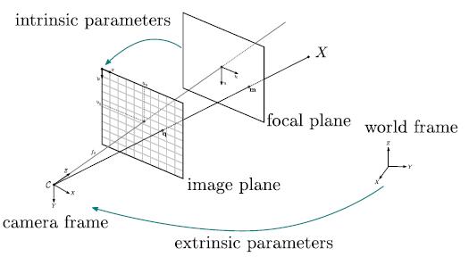
Camera is a device which maps the 3D scene in a 2D plane, Here the camera is considered as a pin hole through which the light rays from the objects is passed and projected to the image plane at the focal length of the camera, Camera intrinsic and extrinsic parameters can be determined for a particular camera and lens combination by photographing a controlled scene. The picture shown in figure 2, gives a relationship between the camera parameters and the real world distances.
Figure 1. Camera & Real world relationship
2.2 Vehicle Detection
Detection of vehicles using camera images has been a well-researched topic. There are multiple algorithms which are capable of doing this. The important aspect of a robust algorithm is its capability to detect multiple kinds of vehicles under different environmental and lighting conditions with high levels of accuracy. Histogram of Oriented Gradients (HOG) [3] is a popular object detection algorithm for detection of vehicles along with a classifier like Support Vector Machine (SVM). Classical HOG algorithm use multi scale based approach to detect objects at varying size which is computationally too intensive as the same detection window passes through multiple scale sizes. We propose a novel enhancement over the classical approach which uses multiple window sizes in order to handle varying object size instead of rescaling the windows. For example, with VGA resolution camera. a vehicle present at less than 20m of longitudinal distance from the camera may be covered using a 128x128 detection window and from 20m to 40m using a 64x64 window and beyond this , with a 32x32 window. In order to ensure proper detection of vehicles with varying colors and types (cars, trucks, buses etc.), multiple SVM feature descriptors are trained each belonging to a typical variation of color and type of vehicle
.The modified classification equation could be depicted as below.

Where Xi is the feature vector of HOG, Yi is the feature vector of SVM trained data and N number of samples per block, M1 is the number of blocks per window for 128x64 M2 for 64x64 and M3 for 32x32 windows.
The advantage of this method is that as can be seen from the above equation that it is more of linear multiplication and accumulations operations and can be parallelized or vectorised easily in
Advanced Computational Intelligence: An International Journal (ACII), Vol.4, No.1/2, April 2017
Digital signal processor (DSP) or Single Instruction Multiple Data (SIMD) kind of architecture at the same time ensuring that varying scales and orientations of the objects are being detected.
The pictures below show the actual detection output of algorithms (marked by bounding box) at various distances when subjected with multiple test videos collected on a test vehicle by TCS.
Figure 2. Vehicle Detection at varying scales of object sizes
The statistics below show the performance of the algorithm under different environmental conditions for different types of vehicles on long hours of real time road data, verified against the ground truth.
Table 1: Vehicle detection algorithm statistics
2.3. Distance Estimation Using Structure From Motion
Camera based structure from motion (SFM) is becoming a promising means for distance estimation in ADAS applications. SFM is attractive due to lower cost as it works with monocular camera and simpler calibration requirements. However the main challenge in achieving the accuracy with the SFM is that there is no fixed baseline available as the vehicle moves. Robust monocular SFM that effectively reduces scale drift in road scenarios has significant benefits for autonomous driving systems.
We propose an SFM approach, which handle scale drift by means of approximate calculation of ground plane. This is made possible by a combination of approaches as multiple cues are used to extract the ground plane information. There are other SFM approaches which take only sparse feature matching for this estimation [4, 5, 6].
Correction of scale drift is the most important factor to get the correct distance to the object. With the information available about the height (h) of the camera installation in the vehicle , the

Advanced Computational Intelligence: An International Journal (ACII), Vol.4, No.1/2, April 2017
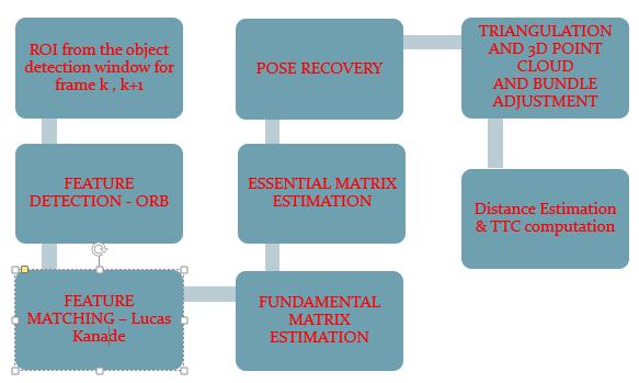
bounding boxes provided by the object detection module is provided as an input to the SFM module, in consecutive frames k and k+1 where the object is detected. Followed by this, the cues extracted from a feature matching algorithm called Oriented FAST and Rotated BRIEF (ORB) [9] is used to extract the features. Generally more popular feature matching techniques like SIFT or SURF is used however they are more computationally intensive. Since the object detection module provides a smaller region on which most of the space is covered by the detected object, ORB itself provides a good feature matching and the advantage is that the time taken is lesser making it embedded friendly. The feature matching is done using Lucas Kanade algorithm which works under the assumption that the neighboring pixels will have similar motion information. Using the matched feature correspondence, fundamental matrix is estimated .Camera matrix obtained from camera calibration is used to calculate essential matrix from Fundamental matrix. Given the projection matrices, 3 dimensional points are computed from their measured image positions in two or more views using triangulation method. Figure 4 shows the intersection of line joining the camera centre and image points x and x0 which will be the 3D point X. From image features xij, structure from motion gives an initial estimate of projection matrices Pi and 3D points Xj. Usually it will be necessary to refine this estimate using iterative non-linear optimization to minimize an appropriate cost function. This is bundle adjustment [11]. Bundle adjustment works by minimizing a cost function that is related to a weighted sum of squared reprojection errors.
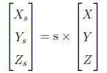
The final stage is resolving the scale ambiguity .As mentioned above, the scale drift is corrected by taking into consideration that the camera mounted height would be above the road surface and hence the mean of Y co-ordinate of 3D points extracted should be greater than camera height.
Then by using the formula, s = H/h where s is the scale, H is the known camera height mounted on the test vehicle and h calculated mean height of 3D points. Multiplication of the scale factor with the generated 3D points(X, Y, Z) need to be done to get absolute 3D point cloud.
Advanced Computational Intelligence: An International Journal (ACII), Vol.4, No.1/2, April 2017
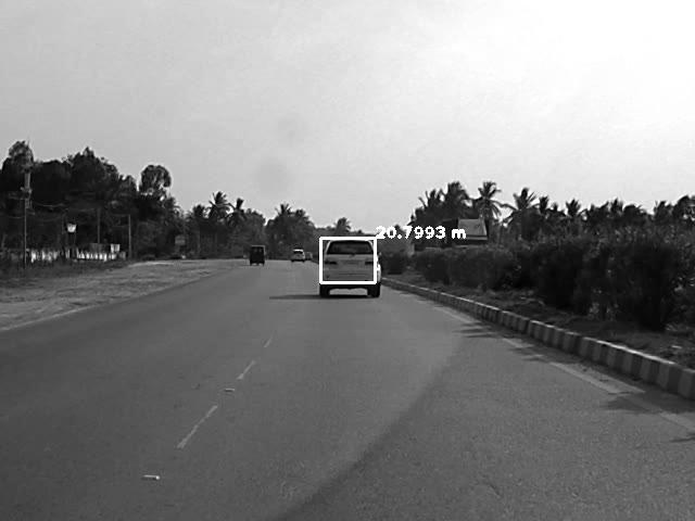
The figure below, shows the distance being estimated by the algorithm.

2.4. Implementation & Optimization on Embedded Processor
Since the requirement of the system is to work in the vehicle, the algorithms and application would need to be implemented on a hardware meeting real time performance .The stringent real time requirement calls for processing the algorithms at a frame rate of 30 per second or a detection latency of 33ms. Most of the existing camera based systems make use of Field programmable gate arrays (FPGA) or dedicated application specific system on chips, which results in higher overall cost .The algorithms considered above are designed in such a way that it can be realized in a more generic hardware chip which makes use of DSP’s and vectorised processing engines which are programmable.
Evaluation of different popular hardware platforms was done and Texas Instruments TDA2x was identified as the suitable one for the system. TI’s TDA2x enables low-power, high-performance vision-processing systems. [5] It features two C66x Digital Signal Processor (DSP) cores and four Vision Acceleration vision programmable engines called EVE’s. Making use of different cores efficiently and creating a parallel processing framework is critical to achieve the real time performance.
The following step by step iterative design and implementation methodology was adopted to optimize the performance of the algorithms.
Figure 5. Optimization process
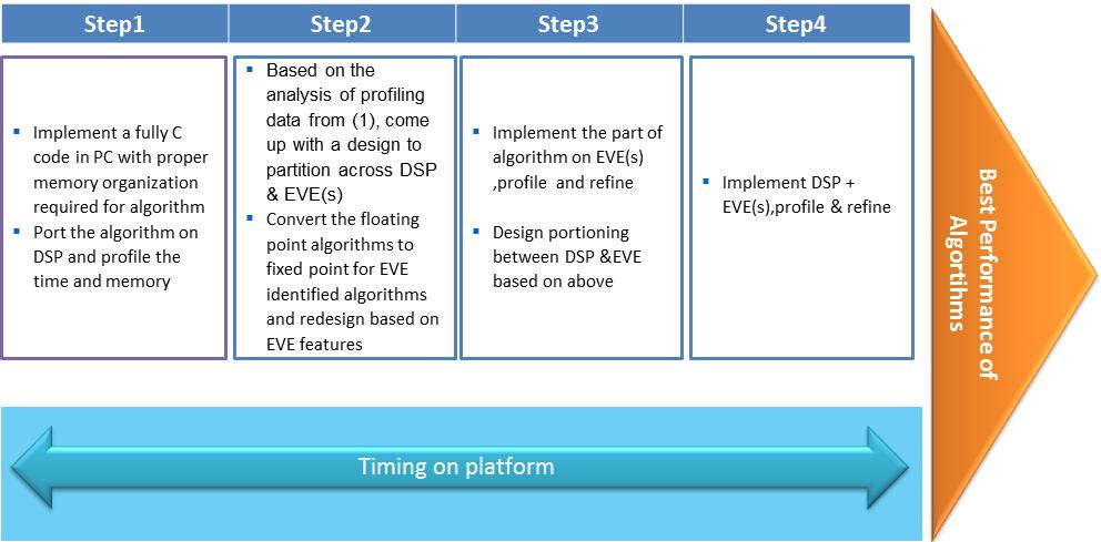
Detailed analysis has been done on the strength of the different types of cores .i.e., DSP, Image processor (EVE) and ARM Cortex .The following table gives the comparative performance of each of the cores.
Table 3: Comparative speedup in different cores
As the above table shows , EVE has a definite advantage on the algorithms which involve fixed point arithmetic whereas DSP offers flexibility in supporting algorithms which require floating point arithmetic to maintain the precision required for higher accuracy.
Based on the analysis done on the algorithm, the following portioning is done for the HOG
detection. As given in section 2.2, the SVM multiplication with the extracted HOG features is a selected candidate for the EVE core, since it is a linear multiply accumulate loop. Floating point to fixed point arithmetic conversion was performed and the data bandwidth was ensured to be fit into 1 integer bit and 15 fractional bits in order to perform multiplication and addition operations on 16 bit EVE Vector Co-processor (VCOP) engine. This enhanced the performance of this block by the order of 3x.
Advanced Computational Intelligence:[
Advanced Computational Intelligence: An International Journal (ACII), Vol.4, No.1/2, April 2017
Figure 6. Partitioning of HOG in TI TDA2x processor
3. CONCLUSION
This paper discussed the development and initial testing results from an alternative FCA sensing approach that uses a forward-looking stereo camera as a replacement for a radar/lidar device as the sole Forward Collision Warning (FCA) sensing mechanism
This paper also provided a discussion about the state of the art algorithms which detects and approves lead vehicle candidates, compute the distances to these candidates for the purposes of identifying potential rear-end crash situations. An efficient implementation of the algorithm on a low cost embedded hardware was also discussed. Results from initial testing indicate this system would be capable of meeting the New Car Assessment Program (NCAP) Forward Collision warning confirmation test requirements
ACKNOWLEDGEMENTS
The author would like to thank Mr.Rajarama Nayak, head of TCS innovation labs for his guidance and support.
REFERENCES
Pre-Crash Scenario Typology for Crash Avoidance Research. National Highway Transportation Safety Administration. - Najm, W.G., Smith, J.D., and Yanagisawa, M.
[2] Development and validation of functional definitions and evaluation procedures for collision warning/avoidance systems. Highway Transportation Safety Administration. - Kiefer, R., LeBlanc, D., Palmer, M., Salinger, J., Deering, R., and Shulman, M.
[3] Histogram of Oriented Gradients (HOG) for Object Detection -Navneet Dalal and Bill Triggs
[4] A. Geiger, J. Ziegler, and C. Stiller. StereoScan: Dense 3D reconstruction in real-time. In IEEE Int. Veh. Symp. 2011.
Advanced Computational Intelligence: An International Journal (ACII), Vol.4, No.1/2, April 2017
[5] D. Scaramuzza and R. Siegwart. Appearance-guided monocular omnidirectional visual odometry for outdoor ground vehicles. IEEE Trans. Robotics, 24(5):1015–1026, 2008.
[6] S. Song, M. Chandraker, and C. C. Guest. Parallel, real-time monocular visual odometry. In ICRA, pages 4698–4705, 2013.
[7] FORWARD COLLISION WARNING SYSTEM CONFIRMATION TEST, February 2013 - US Department of Transportation
[8] Empowering automotive vision with TI’s Vision Acceleration Pac – Texas Instruments
[9] Rublee, Ethan; Rabaud, Vincent; Konolige, Kurt; Bradski, Gary (2011). "ORB: an efficient alternative to SIFT or SURF" (PDF). IEEE International Conference on Computer Vision (ICCV).
[10] 3D Reconstruction Using the Direct Linear Transform with a Gabor Wavelet Based Correspondence Measure Technical Report Daniel Bardsley / Bai Li
[11] RiBernd Kitt,Jorn Rehder, Andrew Chambers, Miriam Schonbein, Henning Lategahn, Sanjiv Singh : Monocular Visual Odometry using a Planar Road Model to Solve Scale Ambiguity.
Authors
MANOJ C R
Solution Architect EIS Innovation Labs, Tata Consultancy Services Email: manoj.cr@tcs.com
Manoj CR is currently working as a Solution Architect in the area of Advanced Driver Assistance System and Autonomous Driving. His primary responsibilities include conceptualizing and designing of new ADAS features. Manoj has 13+ years of total experience with new product development in the areas of Video, Imaging for the embedded products in automotive, consumer devices and industrial domains and holds a Master’s degree in Embedded Systems. Manoj is an inventor of 4 patents in the area of Vision based detection systems.
