
6 minute read
Professional Contributions
Figure 3a. Cross-section of Lake Roland Dam
Damage by Tropical Storms
Tropical storms Agnes (June 1972), and David (September 1979) caused flooding and eroding of the earth and rubble fill on the downstream side of the abutments and non-overflow sections of the dam. During Agnes, flood runoff overtopped the non-overflow section by 3 feet (9 feet over the overflow spillway). Hurricane Connie (1955) caused an estimated discharge through the overflow section of 5,500 cubic feet/second (cfs), which was the maximum discharge capacity. This severely eroded backfill from the downstream non-overflow section slopes, exposing the stone block walls. Some capping stones were dislodged by flood flows. Seepage was observed between stone blocks at several locations of both sidewalls. Capping stones on the overflow sections (crest/apron) were missing or misaligned. Seepage also occurred from a round arch conduit outlet (flow of 10 gallons/minute). The right exit stream bank/overflow section was extensively eroded up to 250 feet downstream (Pictures 2a, 2b and 3).
Phase I Inspection by the US Army Corps of Engineers (USACE)
The Phase I inspection was performed pursuant to authority granted by The National Dam Inspection Act, Public Law 92367, to the Secretary of the Army, through USACE, to conduct inspections of dams throughout the United States. The purpose was to evaluate if the dam constitutes a hazard to human life or property. Site visits were conducted in March 1979 (pre-Tropical Storm David) and September 1979 (post-Tropical Storm David).
The USACE Assessment Included the Following Observations
Dam classified as an “intermediate size,” “high hazard” with a recommended spillway design flood of 100% Probable Maximum Flood (PMF). Non-overtopping flood discharge capacity was only 10% PMF. Predicted failure of dam at discharge of 35% of PMF! At one-half and full PMF, the dam will be overtopped by 7 feet and 12 feet with flow durations of 9 and 10.5 hours, respectively. PMF inflow design flood is 61,500 cfs. Substantial property damage and loss of life will occur in the Jones Falls floodplain – Bare Hills, Mount Washington, Hampden, Woodberry, and Baltimore City. Inoperable reservoir drain slide

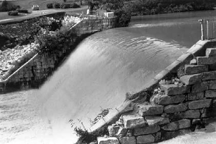
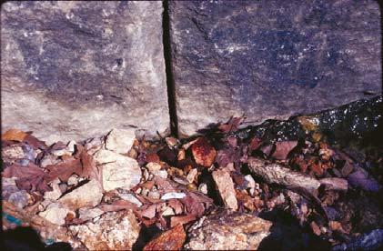


Picture 2b. Damage to left over-flow section of lake


Picture 3. Damage to right overflow section of Lake Roland Dam
gates are inadequate in their present condition. The design is not in conformance with accepted engineering practice even though the performance history of the dam is reportedly good. Stability analysis: Factor of Safety (FS)–normal (overturning, 1.4); Tropical Storm Agnes (slide, 0.9), at 35% PMF (slide, 0.46).
Phase II Inspection by Baltimore City
The Phase I report recommended additional studies to extensively define the dam’s deficiencies. This is the responsibility of the owner and would be termed a “Phase II Investigations.” The city initiated more detailed Phase II studies and the purpose was two-fold: 1) to conduct a detailed, comprehensive engineering investigations and

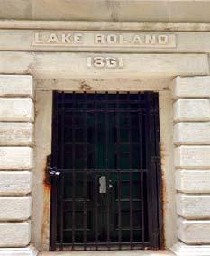


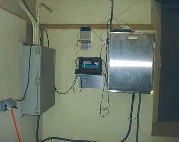
Picture 4. Restored Gate House at Lake Roland Dam
analyses; and 2) to determine how dam deficiencies should be corrected.
The City’s Engineers Observed the Following:
Both non-overflow sections have a variable fill and consist of voids ranging from 0.2 to1.7 feet in size. Volume of mortar ranged from 20 to 85% of total. Dam and abutments had high permeability (10-3 cm/sec). Foundation had permeability of 106 cm/sec. Due to extensive development downstream, the dam must pass the PMF design storm. At PMF, with flow of 51,800 cfs, the overflow sections have 15.5 feet overtopping, and the non-overflow sections have 9.5 feet overtopping.
The City’s Engineers Provided the Following Recommendations in November 1985:
Stabilize dam and construct a side channel spillway, or stabilize dam and lower the existing spillway, or reconstruct the dam to withstand the PMF, or remove the dam. Baltimore City, in consultation with their engineers and regulators, chose the first option.
Rehabilitation of Lake Roland Dam (1993–94)
The rehabilitation was performed in two phases.
During Phase I, the Gatehouse was Restored as Follows:
Gatehouse was restored to its 1861 condition and appearance (Picture 4). Walls were strengthened on the interior with reinforced concrete to withstand pressure of the design flood, and, new timber roof trusses (like the original ones) were fabricated and installed with vent fans.
During Phase II, the Following Structural and Hydraulic Improvements Were Completed:
The new dam would receive only 78% of PMF discharge with a portion of the flow being naturally routed through a railroad cut through the hill north of the dam. Principal spillway lengthened by 50 feet, from 120 to 170 feet long. Slope of the principal spillway was flattened. Reinforced concrete slopes added to N/S non-overflowing surfaces to control flow during overtopping. Training walls built to the elevation of the PMF at both north/south abutments of the dam. Stilling basins with chute and baffle blocks were added to the toe for energy dissipation. Downstream channel was widened on the north side of the dam and armored with gabion baskets and Reno mattresses to accommodate the longer principal spillway. Stability Analysis indicated structural improvements to the dam must involve grout injection, stabilization of existing structure; and mass concrete overlays for existing dam. Injection grouting on 5-feet centers was done on principal spillway, both abutments and 10-feet of underlying Baltimore Gneiss rock using cement grout. Mass concrete overlays were keyed 10-feet into the Baltimore Gneiss formation. Concrete-capped sheet-pile cutoff wall was constructed just below the ground surface to prevent scouring behind the north training wall during periods of high waters. Concrete cutoff wall was constructed below the road between the gatehouse and south training wall. Reinforced concrete armor was applied to the south nonoverflowing slopes below the gatehouse and above the original drain and raw water tunnels (Pictures 5, 6, and 7).
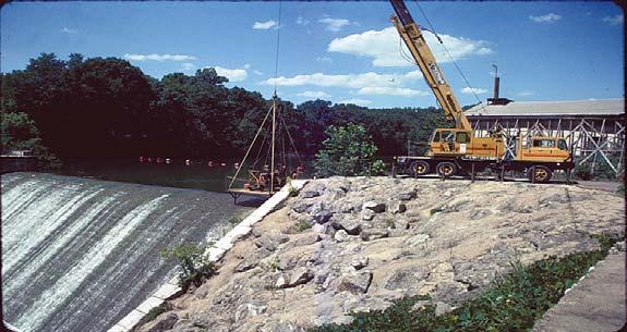


Picture 5. Repairs to left non-over-flow Section of Lake Roland Dam


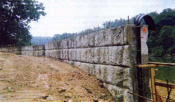
Picture 6. Repairs to overflow section of Lake Roland Dam


