15 minute read
Field Notes: Next Steps


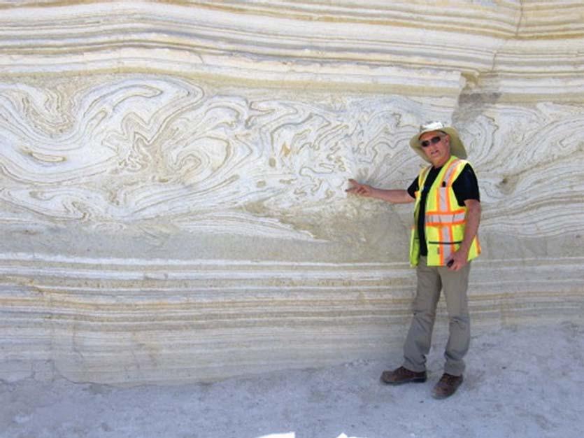
relatively high density of mapped karst features, and sinkholes have caused not only road closures but also the condemnation and demolition of several residences (Kochanov, 1989; Kochanov and Reese, 2003; Miller, 2014; Barr, 2016; Moyer, 2018). The prevalence of sinkhole activity has led some residents to call Palmyra “the sinkhole capital of Pennsylvania” (Kochanov, 1995).
About 0.25 mile north of US 422, lies the Millard Quarry, which at more than 1,000 acres, is one of the largest active surface mining operations in Pennsylvania. Originally known as the Clear Spring Quarry when it opened in 1880, the quarry was acquired by Jacob Millard in the 1890s and operated by the Millard family until the mid-1960s. After changing hands several times, including a period of ownership by the Bethlehem Steel Corporation from 1966 to 1988, Pennsy Supply (a subsidiary of Oldcastle Materials) acquired the quarry in 2001 (Faiola, 2014; Fullmer, 2013). Underground mining began at the Millard Quarry circa 2013.
The quarry extracts dolomite from the Ontelaunee Formation and high-calcium limestone from the Annville Formation (Sims, 1968). The dolomite is used for construction products (hot-mix asphalt and ready-mix concrete), and the high-calcium limestone is used for steel making, industrial minerals, and cement. The quarry has been excavated from 450 feet above to 85 feet below sea level, extends three miles along bedrock strike and about one-half mile across strike. Much of the water pumped from the quarry is used in the manufacturing process and for dust-control (Faiola, 2014). Susquehanna River Basin Commission (2021) records indicate dockets are approved for consumptive water use at the Millard Quarry by Pennsy Supply (555,000 gallons/day) and Carmeuse Lime, Inc. (100,000 gallons/day).
Previous Sinkhole Activity
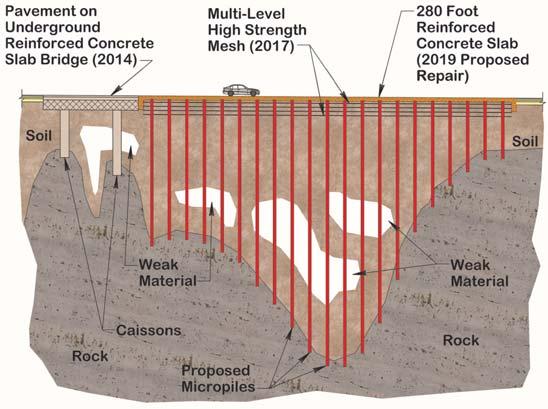
The project site in Palmyra has a long history of sinkhole activity with sinkhole records dating back to the 1950s. A sinkhole closed the center lane of the roadway in 1979, and sinkholes occurred along the shoulder in 1982. A sinkhole at US 422’s intersection with South Green Street was repaired with concrete and aggregate in 1992. New sinkholes occurred adjacent to the roadway in 1993, and the roadway was closed in 2009 to repair sinkholes again with concrete and aggregate. When sinkholes closed US 422 in 2014, a concrete-columnsupported bridge was constructed at grade in the affected area (Figure 3). The at-grade-bridge consisted of a 17-inch-thick structural concrete slab resting on a five-sided polygon of 40inch-wide by 38-inch-deep concrete beams supported by structural concrete caissons having a diameter of 30 inches in soil and 24 inches in rock and installed 5 feet into rock. The design called for five caissons, but during construction, a sinkhole was encountered at one of the caisson locations, so two additional caissons were installed.
In 2017, sinkholes developed in the shoulder of US 422 adjacent to the area of the at-grade-bridge. PennDOT opted to repair the sinkholes with a 30-inch-thick flexible sinkhole safety net consisting of multiple layers of geogrids, geotextiles, and soil (Figure 3). In 2019, a depression was observed to be developing in the westbound lane of US 422 in the area of the sinkhole safety net and adjacent to the 2014 at-grade-bridge. PennDOT was again forced to close the roadway in June 2019.
Figure 3. Schematic section showing 2014, 2017, and 2019 repairs of active sinkhole zone affecting roadway
2019 Sinkhole Repair Design
After closing the roadway, PennDOT engaged Gannett Fleming, Inc. on July 2 to assist with the design of a solution. Due to the tight time frame for reopening the road, a standard subsurface investigation (e.g., test borings and lab testing of samples) was not deemed feasible. The design team had to rely on limited air track drilling data and geophysical information available from previous repair efforts. Within five days, including working through the July 4 holiday and weekend, the project team determined that the safest solution for the traveling public was a structural concrete slab supported by micropiles. The selected solution offered the advantages of easy installation, redundancy, and a low likelihood of catastrophic failure due to future sinkhole activity.
The micropiles were designed to meet American Association of State Highway Transportation Officials (AASHTO) and PennDOT Load and Resistance Factor Design (LRFD) standards. Design details are shown in Figure 4. The design assumed the micropiles have a minimum 5-foot bond length in rock and are subject to compression loading only with no lateral loading and with no group effects or uplift on the micropiles. Material assumptions are listed in Table 1. Based on the design assumptions, the material assumptions, and parameters specified in the design references, the geotechnical resistance was calculated to be 363 kips, and the structural resistance was calculated as 701 kips for the cased length and 327 kips for the uncased length, so the uncased structural resistance controlled the design.
The design called for 84 micropiles in 21 rows, spaced about 15 feet apart, with four micropiles spaced about 10 feet apart in each row. The micropile grid was designed to support
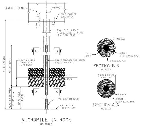
Figure 4. Micropile design details
a 2-foot-thick reinforced, concrete slab 280 feet long and 38 feet wide. Design of the slab thickness was controlled by punching shear. Even as sinkhole activity continues, each micropile will continue to support the slab provided the unsupported length is less than 25 feet. The design was redundant in that it assumed the loss of one micropile per row. The design called for thirty 7-inch-diameter covered inspection portholes to be installed in the slab with a maximum spacing of 45 feet, and a closer spacing in problem areas, in order to permit future monitoring of ground conditions below the slab and to provide potential access points for filling future cavities. Final plans were delivered to PennDOT on July 17, 2019.
Construction
On August 7, 2019, Redstone International began drilling for installation of the micropiles as subcontractor to J.D. Eckman, the general contractor. Two verification load tests were performed to verify the design assumptions, particularly the bond length and the grout-to-ground bond resistance factor, and to assess the adequacy of the Contractor’s installation methods. To pass, the test pile had to sustain the design load (i.e., service load) with no more than 0.75 inch of vertical movement and not fail at twice the design load. Because of the need to test at twice the design load, #24 (3-inch-diameter) bars were used in the test micropiles.
The contractor constructed two verification test piles to depths of 27.5 and 36.5 feet on August 8, 2019. The two load test micropiles were located between production micropiles, which served as reaction piles for the test. The reaction piles could still serve as production micropiles since the total load on them during testing did not exceed the design load. Foundation Test Group, Inc. performed the axial tension load tests on August 19, 2019 (Figure 5). The load tests indicated vertical displacements of 0.10 to 0.11 inch at the design load (220 kips) and 0.25 to 0.27 inch at twice the design load (440 kips), with a net movement after unloading of 0.02 to 0.04 inch.
Redstone International drilled the micropile holes using the duplex drilling method and employing a bit with an outer diameter of 10.353 inches (Figure 6). Geologists or geotechnical engineers observed the drilling, logged cuttings, and terminated the hole after encountering 6 feet of competent rock, which was defined as 6 feet of continuous rock without soil/clay seams, voids, or highly weathered, broken rock. If 6 feet of competent rock was not encountered within 200 feet, then another hole was drilled within 3 feet of the abandoned hole and battered at 2H:12V in the direction where better rock was anticipated based on other drilling results.
After drilling, the contractor tremie grouted the hole until full return of good grout to the surface and then dropped the bar, with three centralizers attached, into the hole. If grout did not return to the surface after pumping twice the theoretical hole volume, then the contractor stopped grouting and allowed the grout to set a minimum of 12 hours before re-drilling the hole to the tip elevation, and re-grouting the hole. On-site grout testing consisted of monitoring grout temperature and measuring unit weight with a mud balance (API RP-13B-1) and viscosity with a Marsh funnel (ASTM C939). Laboratory compressive strength testing of 2-inch cube samples verified that the grout strength requirement of 5,000 pounds/inch2 was met (AASHTO T106).
A total of 89 micropiles were installed (the 84 designed production micropiles, the two test micropiles, and three abandoned micropiles). Micropile lengths varied from 17.5 to 179.5 feet with an average length of about 50 feet. The total length of drilling was 4,436.5 feet, which was about 20 percent less than the estimated quantity. Micropile construction was completed September 13, 2019, followed by construction of the structural slab (Figure 7) and re-opening of the roadway in November 2019, just 18 weeks after the highway’s closure and a week ahead of the scheduled completion date (Figure 8).
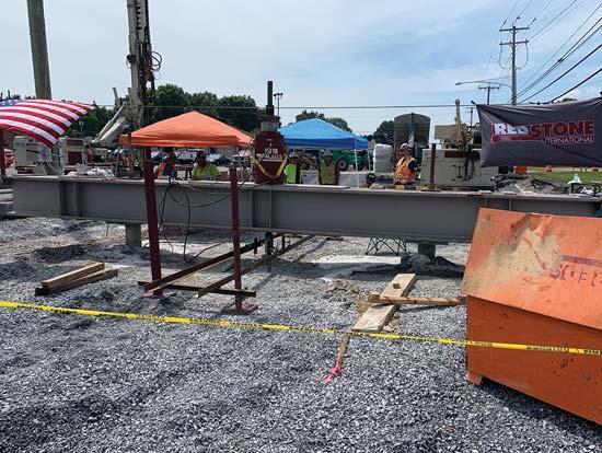
Figure 5. Load test setup showing test beam supported by reaction piles on each side of the test micropile
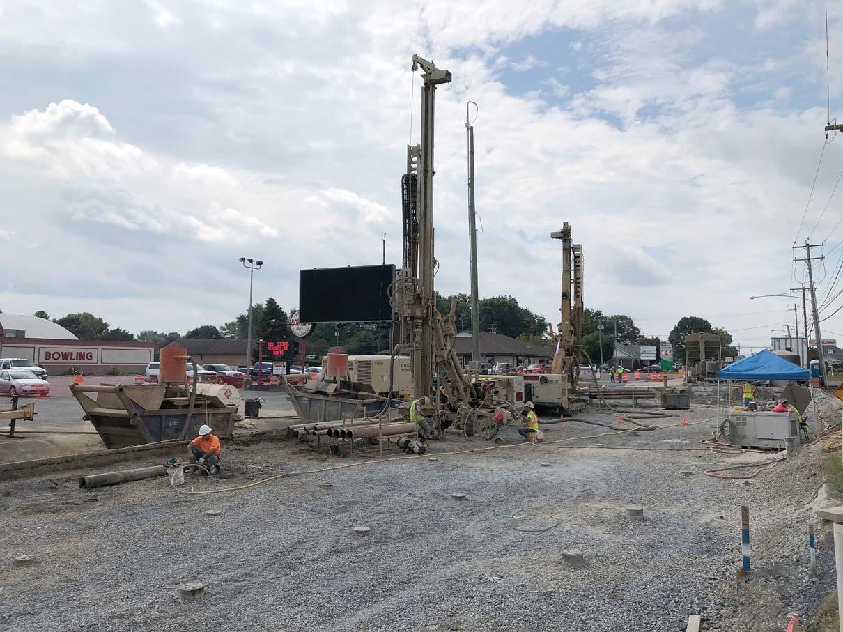
Figure 6. Two drill rigs worked simultaneously to drill the micropile holes. Worker in orange shirt at left is using a yellow, flexible tremie hose to grout a drilled hole. In the foreground are completed micropiles, cut off to the final pile top elevation.
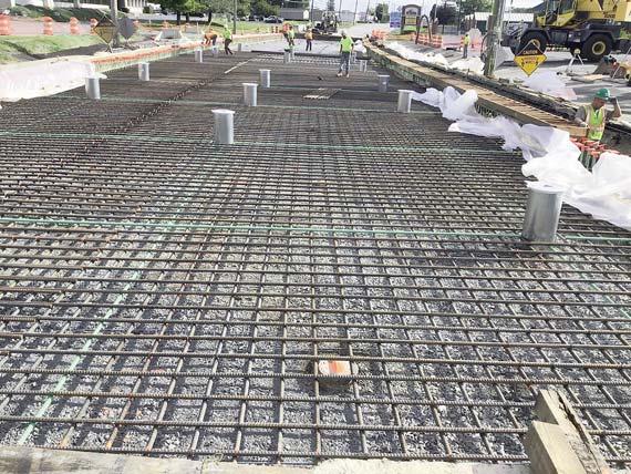
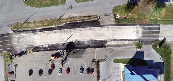
s Figure 8. Drone view of completed roadway repair s Figure 7. Inspection ports were set in place prior to pouring the concrete slab so that PennDOT can monitor the subbase and material under the slab to detect signs of further subsidence.
Conclusion
Carbonates and evaporites underlie about 16.1 and 1.9 percent of the United States, respectively, so about 18 percent of the area of the United States is underlain by soluble rocks having karst features or a potential for them (Weary and Doctor, 2014). Although data are sparse and incomplete, karstrelated damages in the United States are estimated to average about $300 million per year (Weary, 2015). In 2019, PennDOT spent $3.4 million to repair a 280-foot-long section of busy highway underlain by carbonate rock and plagued by chronic karst subsidence in Palmyra, Pennsylvania.
References
(Pennsylvania Geological Survey 4th series publications are available online at https://www.dcnr.pa.gov/Geology/PublicationsAndData/Pages/default.aspx.) Barr, Barbara, July 25, 2016, Palmyra homes demolished because of sinkholes: WGAL News [https://www.wgal.com/article/palmyra-homes-demolishedbecause-of-sinkholes/5979922]. Faiola, Dino, February 17, 2014, Millard Quarry: Pennsy Supply YouTube video [https://www.youtube.com/watch?v=ACXRS3D93ok]. Fullmer, Paul, 2013, Millard Quarry history: YouTube video [https://www.youtube.com/watch?v=E-AgKsx6aB8]. Geyer, A. R., 1970, Geology, mineral resources and environmental geology of the Palmyra quadrangle, Lebanon and Dauphin County, Pennsylvania: Pennsylvania Geological Survey, 4th ser., Atlas 157d, scale 1:24,000. Kochanov, W. E., 1989, Sinkholes and karst-related features of Lebanon and Dauphin Counties, Pennsylvania: Pennsylvania Geological Survey, 4th Ser., Open File Report 8802, scale 1:24,000. Kochanov, W. E., 1995, Storm-water management and sinkhole occurrence in the Palmyra area, Lebanon County, Pennsylvania, in Beck, B. F., ed., Karst Geohazards—engineering and environmental problems in karst terrane, Proceedings, 5th Multidisciplinary Conference on Sinkholes and the Engineering and Environmental Impacts of Karst, Gatlinburg, TN, April 2-4, 1995: A. S. Balkema, Rotterdam, p. 285–290. Kochanov, W. E., and Reese, S. O., 2003, Density of mapped karst features in south-central Pennsylvania and southeastern Pennsylvania: Pennsylvania Geological Survey, 4th ser., Map 68, scale 1:300,000. Miller, Barbara, June 11, 2014, “Demolition appears likely for Cherry Street houses condemned due to sinkholes in Palmyra”: The Patriot-News [https://www.pennlive.com/midstate/2014/06/demolition_appears_likely_f or.html]. Moyer, Merriell, November 10, 2018, “Cherry Street in Palmyra re-opened to traffic after a 4-year closure”: Lebanon Daily News [https://www.ldnews.com/story/news/local/2018/11/10/east-cherrystreet-palmyra-borough-lebanon-county-reopened-sinkhole-stormwater-management-open/1929237002/]. Sevon, W. D., 2000, Physiographic provinces of Pennsylvania, 4th ed.: Pennsylvania Geological Survey, 4th ser., Map 13. Sims, S. J., 1968, Millard Quarry, Annville, Pennsylvania, in The Geology of mineral deposits in south-central Pennsylvania: Guidebook for the 33rd Field Conference of Pennsylvania Geologists, October 4–5, 1968, pp. 52–63 [https://www.fcopg.org/download-guidebooks]. Susquehanna River Basin Commission, 2021, Water application and approval viewer – WAAV: https://www.srbc.net/waav [accessed January 4, 2021]. Weary, D. J., and Doctor, D. H., 2014, Karst in the United States: a digital map compilation and database: U.S. Geological Survey Open-File Report 2014–1156 [https://pubs.usgs.gov/of/2014/1156/pdf/of2014-1156.pdf]. Weary, E. J., 2015, The Cost of karst subsidence and sinkhole collapse in the United States compared with other natural hazards, in Doctor, D. H., Land, Lewis, and Stephenson, J. Brad, eds., Proceedings of the 14th Multidisciplinary Conference on Sinkholes and the Engineering Impacts of Karst: National Cave and Karst Research Institute Symposium 5 [https://scholarcommons.usf.edu/sinkhole_2015/ProceedingswithProgram/] Wilshusen, J. P., and Kochanov, W. E., 1999, Land subsidence—carbonate terrane, Chapter 49A in Shultz, C. H., ed., The Geology of Pennsylvania: Pennsylvania Geological Survey, 4th ser., and Pittsburgh Geological Society, Special Publication 1.
2021Corporate Sponsors Kilimanjaro

The University of Arizona
College of Engineering
(888) 658-2042 1209 East 2nd St., Room 100 Tucson, AZ 85721 onlineengineering@arizona.edu https://online.engineering.arizona.edu/online-eng-mining/
Kilauea
Collier Collier Geophysics, LLC
Phil Sirles, 7711 W 6th Ave., Suite G Lakewood, CO 80214 720-487-9200 https://colliergeophysics.com/

Lettis Consultants International, Inc.
Earth Science Consultants
Ion Bazgan, 1981 N. Broadway, Suite 330 Walnut Creek, CA 94596 (925) 482-0360 http://www.lettisci.com/
Rehabilitation of Historic Lake Roland Water Supply Dam, Baltimore, Maryland
Visty P. Dalal
Visty P. Dalal is a Senior Engineering Geologist with the Maryland Department of the Environment, Baltimore, Maryland, where he has worked for the past 29 years, first as the Division Chief of the Dredging Coordination and Assessment Division and then with the Dam Safety Division for the past 19 years. He is responsible for regulating and overseeing over 100 dams in Maryland, working with the dam owners on maintenance and repairs of dams and conducting county-wide EAP tabletop exercises. He is an active ASDSO and AEG member and has published and presented several technical papers at the ASDSO & AEG conferences and in technical journals over the past 19 years. He is on ASDSO’s ‘Emergency Preparedness & Consequence Reduction Committee’; and AEG’s ‘Dams Technical Working Group and Strategic Initiative Committees’ and is also the Acquisitions Editor for the AEG News seasonal magazine since 2019. Visty has earned double master’s degree in engineering geology from India and the petroleum geology degree from Wichita State University, Kansas. He is an adjunct associate professor at several universities in the country as well as at a local community college. Currently, he is pursuing his doctoral degree research on ‘Characterization of the chenier structures in the Mid-Atlantic Region of the US.’
Historical Significance
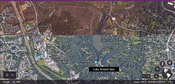
Lake Roland is also known as “Swann Lake” in honor of Mayor Thomas Swann, who began construction of Baltimore’s main drinking water reservoir by acquiring the land and buildings of the Bellona Gunpowder Mill and the Eagle Factory textile works. The present name “Roland” stems from “Roland Run,” a stream that got its name back in 1694 from landowners Roland/Rowland Thornberry who owned a tract called “Selsed.” From 1804 to 1854, Baltimore’s population depended on the privatelyowned Baltimore Water Company for its water supply. The company had built dams in Maryland to meet its customers’ needs. In October 1854, the city’s fathers bought the Baltimore Water Company and decided to build the Lake Roland Dam on Jones Falls (one of the three tributaries draining to Lake Roland). Lake Roland was Baltimore’s first effort to establish a citywide water supply system in 1861. Also, it was nation’s second installation of a hypochlorite water treatment plant, where chlorine was added to drinking water supply for the entire city. In 1915, the dam/lake were converted to a park/recreation facility for the City of Baltimore due to extensive sedimentation (~21,000 cubic yards/year) from tributaries Roland Run, Jones Falls and Towson Run (Figures 1a and 1b; Picture 1). In 1958, the water supply conduit was plugged.
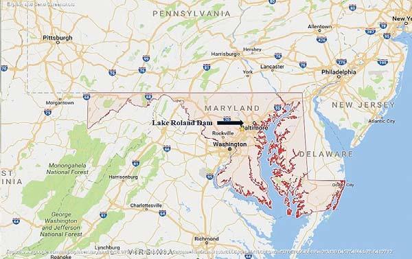
Figure 1b. Regional location map
Regional Geology of Baltimore County
Lake Roland is in the Coastal Plain Physiographic Province of Baltimore County. The predominant geologic structures are the Towson Dome, Chattolanee Dome, and Laurel Belt (light gray to tan dense dolomitic limestone). Lake Roland dam is located on the western edge of the Towson Dome within the Baltimore Gneiss formation. The dam lies 0.2 miles east of the Ruxton Thrust Fault and 0.7 miles southwest of a minor thrust fault bordering the Laurel Belt. The Towson Dome consists predominantly of
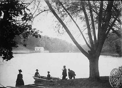


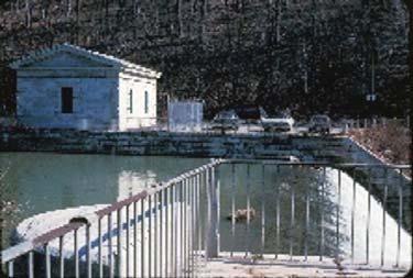
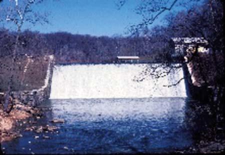
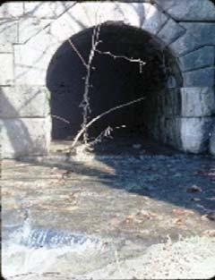
Picture 1. Lake Roland Dam
dark and light biotite-microcline-quartz-plagioclase gneiss. These are highly foliated rocks striking N 70°-72° W and dipping 76°to 90°. The entire dam foundation, including the abutment area, was excavated 10 to16 feet to rock, which consisted of moderately weathered and fractured Baltimore Gneiss. Most of the stones used in the 1861 construction of the dam were local metamorphic rocks from the Cockeysville Marble and the Baltimore Gneiss (Figure 2, MGS, 1976).
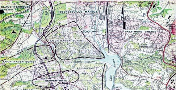
Figure 2. Geologic map of the site
Construction of Historic Dam in 1861
The city hired engineer James Slade, from Hartford, Connecticut, to design the dam. Initially, the dam was supposed to be built of earth and wooden cribs, but the decision was made to build an “indestructible” dam. The concrete/masonry gravity dam was built in 1861, about 0.6 miles north of Baltimore. From its base, the height of the dam was 40 feet to its crest and 46-feet to the top of its wing-walls. The overflow section on top of the dam was 120 feet in length, and the dam base is 60-feet-thick. The core of the dam was built of heavy rubble work ground from neighboring stones. The overflow section (spillway) was constructed of blocks of Cockeysville Marble and extended to bedrock. The non-overflow sections were also constructed of Cockeysville Marble blocks, which measured 3 feet x 2 feet x 1.5 feet. The 16-foot-long stilling basin was located at the downstream toe (Figures 3a and 3b; Picture 1).
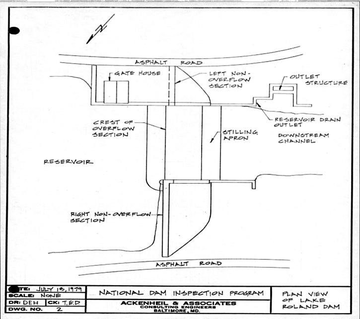
Figure 3a. Plan view of Lake Roland Dam