18 minute read
Lighter Side

by AIRAH


Advertisement

1 WINNER 2 3


4


1 CROWDED AT THE TOP
Jordan sent in this pic from Miranda in Sydney. “Soft drawn slapped in everywhere,” he says. “This is where outdoor units come to die.” Sadly for Jordan, this wasn’t a job he was called out to – he found it when he went to investigate why the AC in his brand-new apartment wasn’t working. Graham says: Just finding the right unit to work on would be a challenge. Often these systems are not designed, they are “sold” by a salesperson and the installer then has to make the best of it. The bottom line is that the price rules.
2 TECHNICOLOUR HVAC
Those of you old enough to remember the Mousetrap game will appreciate Ben’s pic of a bar in Brisbane. Graham says: Wonderful job of brightening up some boring old ducting. So long as the access doors are still usable.
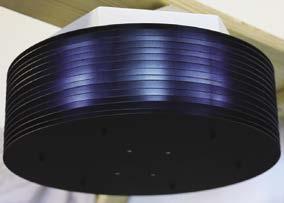
3 TOTAL ECLIPSE OF THE BRAIN
“Came across this beauty on a job in Brunswick,” says Kody. “Package unit completely surrounded by solar panels.” Graham says: Reinforces the need for access walkways on rooftops which make the task of servicing air conditioning units much simpler and also much safer.
5
4 THE ROOT OF THE PROBLEM
Scott was called out to a home in Wynn Vale, SA, because the AC wasn’t working well. “The customer’s back garden was under full pergola,” Scott says, “so they hadn’t seen the air conditioner since it arrived about 20 years prior. “I asked when they’d last had it serviced, and the response was of course: ‘What do you mean, it needs a service!?’ “I’ll never forget the looks on their faces when I showed them the photos. I should have taken that photo! Priceless.” Graham says: While we can be critical of the customer, it was really the fault of the selling agent who didn’t instruct them properly on the need for service. Out of familiarity with our equipment we tend to think that customers understand what we are talking about and have what we would describe as common sense.
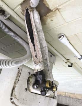
5 UNHAPPY UNION
“Had to replace this unit due to premature compressor failure,” says Aidan. “I think you can tell why. Yes, the flared unions were cut away.” Graham says: It appears that the pipe run between indoor and outdoor unit has been cut back to a minimum, which may have created some flood back, although there should be an accumulator to protect the compressor. The “pair coil” insulation is not great, but may have been cut back for the photo. The apparent close proximity between indoor and outdoor unit could also present problems for noise and vibration through the wall.
Additional comments and observations provided by Graham Boyle, F.AIRAH, portfolio manager, heavy automotive and refrigeration at South Metropolitan TAFE. Please note that the comments are provided on the basis of the photos only and should be read with this in mind – not all issues or solutions are apparent from a 2D image.
HAVE YOU COME ACROSS SOMETHING SCARY, UGLY OR JUST PLAIN FUNNY?
If your entry is deemed the monthly winner, a 700ml bottle of Jim Beam will be on its way to your door. Please include a postal address with your entry. Entrants must be 18 or over. Send your hi-res (>500KB) photos to Editor, Mark Vender at mark.vender@airah.org.au

Ahead of the pack

APAC Commercial HVAC


• Tailored flexibility for all commercial & industrial projects •
• Low installation cost • Low noise


As populations increase and become more urbanised, the demand for trusted, innovative HVAC cooling and heating solutions are greater than ever. Engineered and built in Australia, the industry-leading apac units are ready for new developments and are perfectly suited to replace existing apac units nearing the end of their life cycle. The new apac ranges are manufactured to superior standards, using the highest quality materials and components. Fully MEPS compliant and


Visit apacair.com.au for more information

EMBEDDED CONTROLS

FOR STREAMLINED INSTALLATION
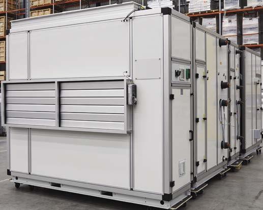
Introducing Daikin Air Handling Unit with Product Integrated Controls (AHU-PIC) – an industry-leading AHU that delivers data-driven insights to assist in the creation of performance-optimised Smart Buildings.
• Quality control and testing performed in factory to reduce risk of issues during installation • Plug and play – BMS contractor can communicate with AHU-PIC via High
Level Interference (HLI) removing the need for field-fitting of controls • Easy access to all components for service and maintenance • Fast and easy installation
Download our brochure to learn more
SMART BUILDING FRIENDLY PLUG AND PLAY
REDUCE CARBON FOOTPRINT DAIKIN FACTORY QUALITY ASSURED
Provide more efficient installation and maintenance solutions to your clients with our comprehensive product line-up. Visit commercial.daikin.com.au or call 1300 368 300
PROUDLY SPONSORED BY
Skills summary
■ What?
A guide to inverters in modern air conditioning units and some common problems you may encounter in the field. ■ Who?
Relevant for HVAC&R technicians and anyone involved in installing, commissioning, and maintaining air conditioning equipment.
INVERTER
DIAGNOSTICS AND TESTING – PART 2
One of the most common ways to modulate the cooling capacity in air conditioning systems is via inverter technology. An inverter controls the speed of the compressor to change the refrigerant flow rate. The turndown ratio depends on the system configuration and manufacturer. Inverter technology is commonplace in today’s air conditioning systems, from commercial units through to residential split systems. Often, issues with the inverter will cause the system to stop working. This Skills Workshop looks at common causes for these issues and describes how to fix them.
Logic control
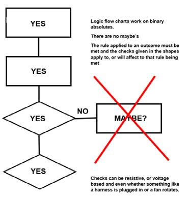
Every supplied air conditioner that comes with micro-processer control is a ready-engineered direct digital control (DDC). What separates one brand from another comes down to what is flashed up in the memory as intellectual property for control parameters/operation and the other proprietary unit designs or exclusive OEM components. Without that, the unit won’t do much other than be an interface for connecting components, sensors, inputs, and outputs. It’s a shame really that customers do not see the amount of work and thought that goes into logic-based control for air conditioning. Over the years there has been improvement on improvement. Good working models have sensors that can be multi-tasked to perform multiple operations and, in the case of energy saving needs, adjuster performance in real time. Control comes in both operation and monitoring. Like any Boolean equation, everything has a rule to work to. These rules are absolute – they have to be – with the main variable being what the operator wants to do and external influences. The service manual is the rulebook, and examples of logic are everywhere: fan staging control, compressor control, temperature, defrost and fault detection. Thermistors, current and pressure sensor information are major players in operation and provide much of the limiting control to protect the system while providing maximum capacity for the customer. A paired system considers itself first, and while there might be overriding host control from network interface, their own rules come first. When analysing systems , knowing what rules apply matters to a service technician. In many examples, systems are not faulty but may be reacting to logic rules overriding good performance caused by conditions outside the system’s control. Excessive defrosting or low performance may come down to how that unit was installed and logic being applied to invariant conditions where something is not changing. When analysing faults through error codes, a condition is met when the rule of that condition has been met. It has a reason, a value, sometimes a timeframe and an outcome. There is no ambiguity here, so when fault-finding, use an error code logic flow charts to help determine what directly results or can be associated with that fault. There are no maybes, and everything outside that fault code’s condition rules should be ignored. It tends be accurate mostly, but logic can be a hinderance when components , especially analogue ones, start to malfunction. Faults can be the result of direct and indirect component feedback. This includes everything from an obvious temperature trip from a compressor overload to a safety or low-performance mode caused by refrigerant restriction. And many problems come from setting errors from first commission. Here someone has locked in a value and locked something else out. So, if you are testing parameters, the operating logic should be used for that component or function as stated by service information. If you are checking a fault code, look at the reason, the condition and the rules that apply.
Logic flow chart – example
Inverter PCB and compressor
At the What Would Dennis Do? website, I receive lots of questions about inverters. Many technicians have trouble grasping the fact that the compressor is run by a power transistor, which can be quite small in comparison to a loadbearing contactor. Many think the PCB wont last. In fact, it is quite the opposite where longevity of the product really comes down to the environment and quality of installation. AC compressors are a thing of the past now. ABB produces a SynRM synchronous reluctance motor now that no longer uses direct grid AC into an induction motor. Unlike permanent magnet motors that we see in inverter compressors, the SynRM works on a temporary magnet principle. As there is no induction it does not suffer I2R losses. Yet it is driven just like inverter compressors by a complex driver circuit to ensure a smooth rotational start. Permanent magnet motors using high-strength neodymium rare earth magnets are suited well for air conditioning needs. The object here is to suffer minimal losses while providing extra motor torque at low and high
speeds. The whole point is to vary refrigerant flow and save power at partload conditions. The compressors are star wound and windings are tested no differently from their AC counterparts. Scroll compressors are directional and most brands use phase rotation detect circuits on larger three-phase class systems. With smaller single-phase splits, make sure the U,V,W colour scheme matches the circuit drawing. The biggest issue onsite for many is testing out the compressor and/or the driving PCB. In some cases it is difficult to check inverter PCB is faulty or the compressor is faulty, e.g., locking. Many of you reading this workshop have been to manufacturer training sessions, used service manuals and likely purchased tools such as inverter checkers/analysers. So, to save a bit of time and not complicate matters , source all information first and apply it through resistive checks on primary components and any other given tests. Although fault codes will give you direction and test requirements, knowing about the flow of power across the boards is always a good start. This workshop will not go through every possible inverter circuit – that’s for the manufacturer training sessions and the manuals to explain. The simplified image shows power flow across inverter printed circuit boards.
When testing inverter system for faults or problems, acquaint yourself with the flow layout of your model and electrical drawing. Chances are it follows the above image from source power in, to conversion of power to the compressor. The following applies in most designs of air conditioner, from domestic to commercial. They operate in a very simple way.
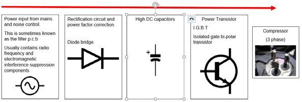
Simplified Inverter power flow
1. Supply power
Enters and is filtered using common mode chokes, low-pass filters and typically electromagnetic and radio frequency suppression. Unwanted power noise and high frequencies from the lines coming in are dealt with before rectification. Usually here you will also find high-voltage surge arrest components such as varistors.
2. Rectification and power factor correction
In some models these can be two separate parts or one component. Whenever switch mode power supply converts mains power, it leaves fragments of the original waveform that have to be dealt with. The power transistor needs linear switching to work effectively, which is taken care of at this point.
3. High DC power capacitors
These do a few things but are hungry for current on start-up. Resistors are sometimes used in series as a prestart to reduce the in-rush current and then switch out for full operation. These are the resistors that smoke up when shortcircuits occur in the DC side. Also, a very important safety note: the metal top of the capacitor is live, so exercise all caution. ELV or extra low voltage is below 50V, and ensure capacitors are discharged prior to servicing.
4. Power transistor
This is the business end of the conversion, which replicates three-phase power to the compressor. These can take a lot of current and a lot of switching speed and are tough. They have one major weakness and one major need: shortcircuits in the compressor such as full earth fusion or very low-ohm fusion events take them out. Their major need is cooling since they generate heat. Good heat transfer is needed between the transistor and the heat sink. Some clever brands now employ assisted fin cooling, using the refrigeration network piping and a dedicated fin cooling heat exchanger. Fin cooling is essential. A couple of tips here: • Use the correct or recommended heat transfer agent. • If you have a horizontal discharge dual-fan outdoor unit, usually the first fan that starts and the last fan that stops services the heat sink. It is possible to plug the fans in to the wrong fan sockets, and mostly the logic will not
worry since it will see a position response from any condenser fan. This can cause fin overheating, so double-check they are in the right outlets. • Once you start exceeding approximately 92°C, the fin thermistors detect radiant energy rise until they deem an operation halt followed by an error code. This is the first sign to check.
The power transistor
An isolated gate bi-polar transistor works as follows:
There is a positive and negative transistor to replicate the AC sine wave. Bi pole means “two poles”, so two per pole or two per phase. Since we have a threephase there will be six in total. The isolated power supply drives the base for each gate, isolated from the CPU, which is the “driver circuit” and separates the high DC power for conversion. The CPU is protected as it uses a light-sensitive opto-isolation circuit; the optocoupler is a light-sensitive transistor that drives the isolated gate drive to open and close the power transistor. The computer side is protected by a beam of light, which is quite amazing thinking. Failure of the driving circuit comes down to CPU error in switching the power transistors at the right time and speed. The power transistor itself is subject to any fusion load issues. So, issues such as gates being on at the same time causing a power shoot through or not opening at speed or at all, can occur. And we have just the tools for that one.
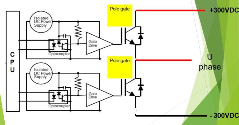
IGBT Switching by CPU (example showing one phase)
Inverter tester/checker
But testing, ask these questions: • What is the law in my state on live testing? • Am I competent to do this test? • Is the device secure and the area secure prior to testing? • Can this device be fitted safely? Most importantly, if there is a resistance-based transistor test available or recommended, you always should consider that the first option or the only option. These testers can validate a fault detected by resistance.
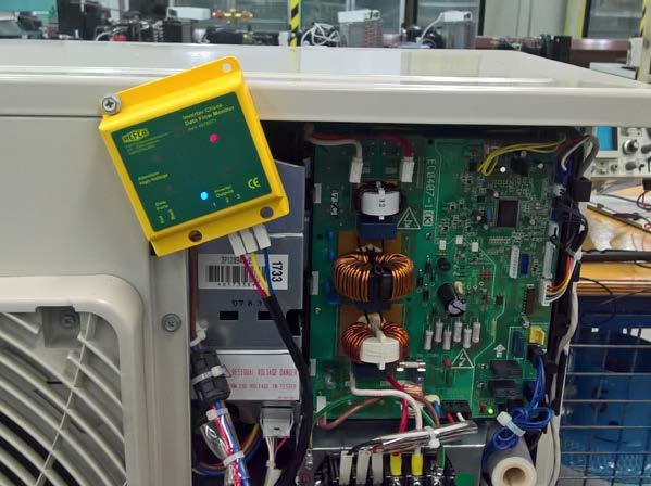
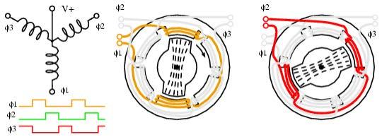
Image courtesy Dennis Kenworthy
If using an inverter tester/checker/analyser, its primary job is to look at the what the six power transistor gates are outputting. Here voltage is not the key player, although it is well present during operation. There are three scenarios possible when using these.
1. Power transistor check mode
If the system has a power transistor check mode, this allows for IGBT output constantly without faulting on zero current and compressor rotation position feedback. The output is at low frequency, otherwise all these LEDs would be lit solid due to high speed. These provide the luxury of time so you can really be sure. For a unit to be operating correctly all LEDs must flash at the same time, speed and interval and never stay on or off. This is a “qualitive” measure of the human eye. After testing, the LEDs go off and may come on again due to a phase discharge function when the on gate is closed to bleed power down for safety. This is normal and many systems do this after compressor stop to prevent high power being locked in circuit.
2. Quick test
Sometimes there is no transistor check mode, but you still have a start and stop window. Most air conditioners use time guard logic to delay first start from power on for 3 minutes, and between compressor operation. Set the mode on, wait 3 minutes, and then you may have up to six seconds to view the output before the system detects current and position fail causing an error or a retry start. Some models might have longer times – check with the brand.
3. No test possible
Some models just won’t tolerate a disconnected compressor, even for a microsecond. In that case, this test won’t work.
Compressor
To finish this insight into inverters, let’s look at the compressor. Typically, they have a three-phase star wound, permanent magnet motor. Scrolls have more compression surfaces than reciprocating in one RPM, so are very good for air conditioning efficiency. Driver circuits that control compressor rotation are complex and always monitoring the rotor position. A permanent magnet follows a rotating field effect, but if the field position changes incorrectly this could stall or create unbalance in the compressor. Fortunately, the rotor has kinetic energy on mass, which keeps turning during the zero-power moment. The position signal allows the drive to know which next winding phase to fire to keep advancing the rotor – that’s the complex job. To do this it requires a position signal feedback sensor. There are two distinct designs: • 3 pin (3-phase inlet) (sensor less feedback U,V,W) • 4 pin (3-phase inlet), fourth pin outlet (direct feedback U,V,W + N) The 3-wire circuit uses a sensor-less system to detect back EMF; it uses motor terminal voltages. There are a number of detection methods that can be used, such as when one phase is at zero or sensing which phase is being unused during cycle operation. These detections are responsible for the errors produced when the compressor does not start or fails to rotate at speed. Mechanical locks are rare in compressors. Confusion exists about whether a compressor is locked or the driver/IGBT is faulty. Eliminate all possibilities and follow the directions on error codes in the service manuals. Power transistor check modes ignore position and current feedback from the compressor. If the compressor is not disconnected for an inverter checker and left on during this mode, you will hear the compressor turn over slowly. That proves a non-mechanical lock. If the system drops out as soon as it starts, ignoring the position signal system can help test that out, but it is not absolute. Importantly, position faults can occur for many reasons not related to the compressor, such as PCB dry joints and socket corrosion, but this is an environmental influence. In my experience, as long as the output from the transistor is balanced, compressor position faults are very accurate, and the compressor may need an inspection. If a system is horribly overcharged, this can cause mechanical lock. Always review the service manual, think about what information it provides, and how it can help onsite. Attend the manufacturer training sessions too – technology changes very quickly. Don’t be afraid to ask those burning questions. Importantly, do not be overwhelmed by these systems. Once you look at many you will see many similar arrangements and testing approaches. Just be aware that readings and voltages differ between brands, as does layout of components. The above is based on my experiences and actions onsite. Always contact your brand manufacturer/agent for advice and service on their product. ■
This month’s Skills Workshop was provided by Dennis Kenworthy, Affil.AIRAH, lecturer at South Metropolitan TAFE, WA and administrator of the website What Would Dennis Do? www.whatwoulddennisdo.com