23 minute read
Worldskills Update
from HVAC&R News June-July 2022
by AIRAH
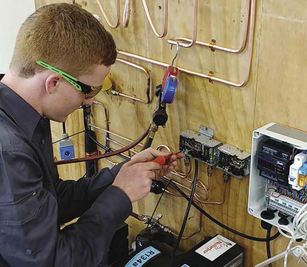
Clancy competing at the “skill off”.
DESTINATION: SHANGHAI
Advertisement
We caught up with Perth-based fridgie Tom Clancy, who will represent Australia at the 46th Worldskills International Competition in China.
Western Australian Tom Clancy is about to enter the elite club of people who have represented their country at an international competition. Some compete in the pool, others on a running track. Tom will fly the flag by working on air conditioning and refrigeration equipment at the 46th Worldskills International Competition in Shanghai in October 2022.
It might not get the same coverage as the Olympics, but the WorldSkills International Competition is huge. The previous event, held in Russia in 2019, brought together crowds of more than 250,000 people to watch more than 1,300 competitors from 63 countries competing across 56 different skills. And even more fanfare and fireworks are expected in China.
HANDS UP FOR WORLDSKILLS
It’s something Clancy couldn’t have dreamed of when, one day at South Metropolitan TAFE, lecturer Keith Glenn, M.AIRAH, came into the class and asked who wanted to compete in WorldSkills. “No one else put their hand up,” remembers Clancy. He admits that back then he didn’t even know what WorldSkills was. “But me being young, I thought, ‘I like my chances here. I don’t know what it is, but I’ll have a right good crack!’ ”
Clancy made it through the regional competition, and went on to compete at the nationals. Although he didn’t make the top step that time, gold medallist Cameron Harrison finally could not commit to the training and travel demands of the international competition. WorldSkills looked to the runners-up: Ryan Hanns from the ACT, and Tom, from WA.
Both went to Brisbane for a two-day, head-to-head “skill off”. Co-ordinating the event was WorldSkills international training manager and expert Carl Balke, Affil.AIRAH, who has been involved with WorldSkills for almost 20 years, and trained Patrick Brennan to a bronze medal in 2019.
Balke admits that after the two days it was still almost impossible to declare a winner.
“It was close, like splitting hairs close,” he says. “We looked at the marks and we looked at their personalities – their traits and their weaknesses. In six months we’ve got so much work to do, so many pressures, so many challenges. Are they going to be able to do it? Have they got the skillsets to improve again?
“In the end, Tom showed the best attributes to go forwards.”
SHANGHAI SURPRISE
When he got word that he was heading for Shanghai, Clancy says his first reaction was surprise, followed by: “Righto, let’s go!”
Back at home in Perth, where Clancy works in the family business – Central West Refrigeration – the reaction was not just one of surprise, but incredulity.
“They didn’t believe me,” says Clancy, laughing. “Gotta be honest. Then I sent them the email from WorldSkills, and they retracted that statement and said ‘good job’.”
Despite the whirlwind couple of months, Clancy says he is keeping his feet on the ground. “The mentality really hasn’t changed that much,” he says. “It’s still get in, get it done, do it as neat as you can, get it cold. That’s the bare basics of it. Training has changed – it’s now bigger projects and all the finer details, which you’ve got to focus on. It’s repetition in the smaller things: get the TX valve bulbs real tight; make sure the solders are real smooth; pipework straight and parallel – keep it neat, keep it saddled, don’t mess it up!”
That may sound obvious, but WorldSkills takes these tasks to another level.
“It’s a lot higher standard than what is out in the field,” Clancy says. “Something you might do out in the field and think is schmicko is worth one point, but the top mark is three points. It’s a step up – a new game.”
Balke offers the example of a three-point solder.
“Obviously a zero is solder down the side and leaks and wrong alloy and all the rest of it,” he says. “But to get that 2mm ring of solder perfectly, without any runs, any dags, is very hard to do under pressure repetitively. It’s robotic, almost manufacturing-like. There’s not many threes given out by the judges.”
STAYING COOL UNDER PRESSURE
A big part of Clancy’s training will be to do these tasks over and over until they are committed to muscle memory. This will be absolutely necessary if he’s to compete with some of the other teams, who train full-time for WorldSkills, six days a week, living in their colleges. Fortunately, Balke says that Australia has the edge in other areas.
“We can adapt to changes,” he says. “If the unexpected turns up, we can work our way around that. So, to be in the hunt for it, that repetitive work has to be perfect – not nine out of 10 times but every time. That way
TAKING A STAND
Earlier this year, WorldSkills International took the decision to ban Russia and Belarus from participating in WorldSkills Shanghai 2022.
“WorldSkills is politically and denominationally neutral,” read a statement issued by WorldSkills. “The invasion of Ukraine by Russia is a clear and enormous breach of our Code of Ethics and Conduct. Belarus, by its active support of Russia’s invasion, has also breached our Code of Ethics and Conduct.”
The decision came partly from the origins of the WorldSkills. It rose out of the ruins of World War II, which devastated economies and created a huge skills shortage that threatened a new economic depression.
“WorldSkills is steadfast in our support for the people of Ukraine, WorldSkills Ukraine, and using skills to build respect, dignity, peace, and prosperity around the world,” said the organisation. ■
The WorldSkills 2019 International Tournament in Kazan, Russia, brought together crowds of more than 250,000 people.

when something does go wrong you can adapt to it, and then when you get into the fault-finding modules, you nail them to get in front of the game.”
The right attitude, Balke says, is also critical. “It’s a four-day competition,” he says, “not just an hour. And you’re going to get a kick in the guts – you’re going to make a mistake. You’ve got to be able to go to your Plan B and still make it work and get maximum marks. And when you have a shit day of training and you want to throw the tools, you come back and do it again. Maybe tools do get thrown, but it’s that coming back that we’re looking for, and that resilience to do it again.” As part of the preparation for the big event, the Skilleroos attended a team-building weekend in Melbourne in April. There, Clancy started to show some of the qualities that will hold him in good stead over the coming months – in particular a competitive streak.
“There’s a competitive nature in there,” says Balke. “He’s surprised quite a few people and that’s because of the quiet Tom we thought we were seeing. But we’ve got a dingo here that’s about ready to pounce.” ■
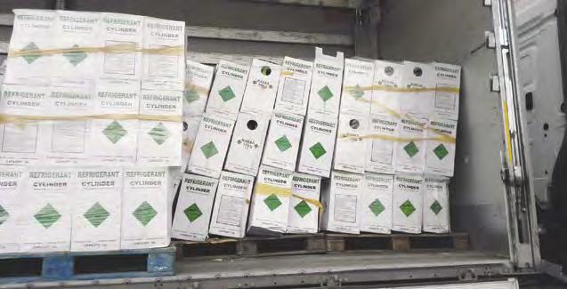
WorldSkills acknowledges its major sponsors: Kirby and Refrigerant Reclaim Australia.

THE LONG GAME
In October, all eyes will be on the medal-winners. But WorldSkills has a purpose much greater than the event itself: to build a “skills culture” and promote vocational education and training, trades and apprenticeships. The importance of this mission is reflected in Tom Clancy’s own experience at high school. “I was doing well in school,” he says. “I was good at maths, I was good at physics, but I just wasn’t focusing. Dad is a refrigeration mechanic, so he said, ‘Why don’t you do some work experience while you’re still in Year 10?’ I organised with the school to do that. But at the end of Year 10, they wouldn’t allow refrigeration as a school-based apprenticeship because they had never done it before.” Both Clancy and his trainer Carl Balke, Affil.AIRAH, acknowledge the difficulties schools face in offering refrigeration and air conditioning apprenticeships: licences for refrigerant handling, for example, and the liability issues of students working in the field, rather than in a workshop. But they also say the problem is deeper than that. “Schools are making you choose [a vocational pathway] from Year 9,” Clancy says, “and in Year 9 I didn’t have any idea what I was going to be doing. It was a very tough call to make.”
Balke points to an even bigger issue – the perceived superiority of university education over VET. “Trades shouldn’t be your Plan B,” he says. “They should be a strong up-front option.” ■
PROUDLY SPONSORED BY

Skills summary
■ What?
Relevant for refrigeration and air conditioning technicians.
REFRIGERANT MANAGEMENT
Most of today’s air conditioning and refrigeration systems use a vapour compression refrigeration cycle that relies on a working fluid, or refrigerant, to transfer heat from one part of the system to another.
This Skills Workshop looks at detecting leaks, repairing systems and handling these refrigerants.
OPSGG legislation
The legislation supporting the Ozone Protection and Synthetic Greenhouse Gas (OPSGG) Program implements Australia’s obligations under the Vienna Convention for the Protection of the Ozone Layer, the Montreal Protocol on Substances that Deplete the Ozone Layer, and the United Nations Framework Convention on Climate Change and its Kyoto Protocol. The Ozone Protection and Synthetic Greenhouse Gas Management Act 1989 and related Acts (the Ozone Acts) protect the environment by reducing emissions of ozone depleting substances and synthetic greenhouse gases. The Ozone Acts control the manufacture, import, export, use and disposal of ozone depleting substances and synthetic greenhouse gases and products containing these gases. These gases are commonly used as refrigerants in refrigeration and air conditioning equipment and so refrigerants need to be managed appropriately. Leak detection, repair and refrigerant monitoring are all important elements of a refrigerant management system. Common causes of poor operation in a refrigeration system are overcharging, undercharging, blocked tubes and capillaries, non-condensable gases, low compressor efficiency and poor heat exchanger surfaces. Of all of these issues, undercharged systems due to refrigerant leakage and blocked or restricted heat exchangers (evaporators and condensers) through lack of maintenance are the most common.
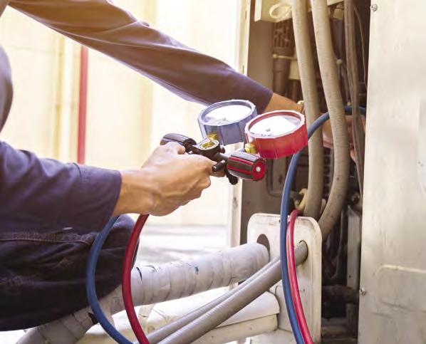
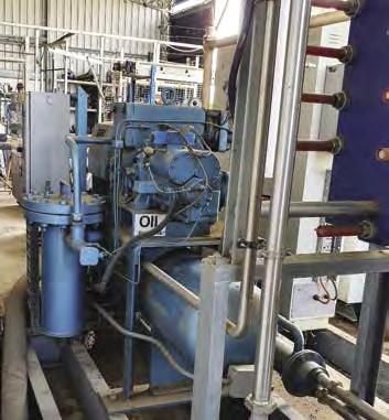
Leak detection methods
Note: AS/NZS 5149.2 and .3 have requirements for leak detection in manufacture and installation/commissioning and the use of permanent detection in a variety of circumstances of space occupancy and refrigerant type. Refrigeration plant will work at its optimum performance only if it contains the optimum refrigerant charge. Refrigerant leaks are bad for system performance, bad for the environment, bad for work health and safety and are often illegal if known. Prior to replacing leaked refrigerant, the leak must be located and repaired as soon as practicable. There are two categories of system leak detection methods: global detection methods determine if the system is leaking, and local detection methods are used to locate the leak area. Some methods can be carried out on a charged system and others require an empty system. Some methods are suitable for use in a manufacturing environment while others are more suited to site or field use. The following are the most common methods used for refrigerant leak detection:
Visual inspection
Generally suitable for site testing components and systems. Large leaks may be evidenced by visually inspecting for traces of oil staining at the joints. This method is suitable for detecting a leak location.
Soap bubble tests
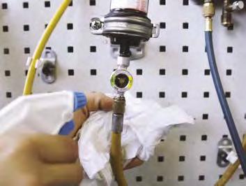
Generally suitable for site testing connections and pipework. Leaks from a pressurised system can be identified by applying a soapy bubble solution to the suspect area. Bubbles form when a leak is encountered. This method is suitable for detecting the leak location.
Pressure testing
Generally suitable for site testing components and systems. The system (or portion of system) is sealed off and pressurised. The internal pressure is monitored by gauges or similar and any decrease in pressure (after accounting for temperature changes) indicates the presence of a leak. Oxygen free dry nitrogen (OFDN) is often used as the pressure test medium. Adding 5% hydrogen can assist with leak detection. When a pressure test is to be carried out it is important to ensure that the compressor is isolated to avoid any damage to the compressor valves and prevent rupture of any crankshaft seals. All pressure controls must be disconnected or by-passed.
If the expansion valve is not capable of withstanding the test pressure then it too must be removed or by-passed. The OFDN cylinder must be fitted with an approved pressure regulator to control the test pressure. For safety reasons a pressure relief valve pre-set to the test pressure is recommended. Alternatively the system can be subjected to a vacuum pressure test. The required pressure difference is created by creating a vacuum within the system. A disadvantage of the vacuum method is the potential ingress of air or water into the system through the leak site. A second limitation is the difficulty of achieving the required test pressures in the field. Pressure testing will not identify the location of a leak. The system must be observed over a period of time, relative to the size of the system, to ensure that no pressure drop occurs, having due regard to temperature variation throughout the system.
Electronic leak testing
Generally suitable for site testing components and pipework. Electronic leak detectors come in a variety of technologies including heated diodes, infrared sensors, and electrochemical sensors. Some devices detect actual refrigerant concentrations, some detect variations in concentration, some detect a substance “other than air” while the more complex or capable versions will indicate the refrigerant being detected. Some systems are more sensitive to particular refrigerants and sensitivities can be adjusted. Proximity and concentration programming can assist the device in leading the operator (closer) to a leak. Manufacturers’ application and operating instructions should be followed.
Ultrasonic leak testing
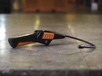
Generally suitable for site testing components and pipework. Ultrasonic leak detectors detect the ultrasonic noise created by the leak of any gas, from pressure or to vacuum, to help find a leak. An electronic conversion process translates this ultrasound into true audible sound that helps the user identify and find leaks through headphones. These detectors may be affected by other sources of ultrasonic noise but these can be tuned out by the detector.
Fluorescent leak detection
Generally suitable for site testing components and systems. The charged system is infused with a small quantity of fluorescent additive. Leaks are identified by the use of a UV light which causes the fluorescent additive in the refrigerant to visibly fluoresce, showing the leak. In the case of slow leaks it may take days or even weeks for the dye to reach the hole and leak out. A larger leak will be detected in only a few hours after injection. Electronic detection can be combined with fluorescent dye detection to counter situations such as intermittent leakage or wind in outside locations. Intermittent leaking can occur when oil or particulate matter temporarily plugs a hole. The dye will confirm the leak visually at a specific location. Note: Great care needs to be taken with the handling of the fluorescent additive, careless handling can lead to liberal coverage all over the plant which means that it becomes difficult to detect the actual leak. If the additive is not compatible with all of the components and materials in the refrigeration system a thorough clean up is required after this process to ensure that the refrigerant and oil do not contain any residual traces. Some additives are designed to be left in the system. Manufacturers’ instructions should be followed. Note that some manufacturers may void any warranty if a substance other than the original refrigerant or oil is added to the system.
Mass spectrometer
Generally suitable for factory testing of components. The unit to be tested is evacuated and held in an environment surrounded by a helium/air mixture. The vacuum is sampled through a mass spectrometer to detect any trace of helium internally. This is a highly sensitive leak detection method. This method will not locate a leak. Alternatively, the system can be pressurised with helium, placed in an evacuated chamber and the chamber monitored for leaks with a mass spectrometer.
Submersion testing
Generally suitable for factory QC testing of components. The test article is sealed, pressurised and fully submersed in a water bath. Leaks are identified by a line of small bubbles. Effectiveness depends on examination methods. This method will locate a leak.
Halide Lamps
Use a naked flame passing over a length of copper wire. The flame will change colour when a leak is detected. They are only suitable for use on refrigerants containing chlorine (CFCs and HCFCs). They will not detect leaks on any of the current HFCs (R134a or R404A etc). They must not be used on HC (hydrocarbon) systems due to the high flammability of these refrigerants (apart from the fact that they will not work anyway). Warning: Halide lamp leak detection methods which use a naked flame in the detecting apparatus are not recommended due to the potential for flammable refrigerant to be present in a system.
Testing for leaks
When testing for leaks, ensure that there is a positive pressure in the system and always ensure that the area is well ventilated. Fans or windy spots are not needed; still air is best for leak detection and as refrigerants are generally heavier than air, leaked refrigerant may be detected well away from the actual leakage point. Always stand to one side of the detector in case there is a sudden violent discharge from the suspected pipework. The most likely points for refrigerant leaks are at the flared, flanged, brazed or soldered joints in refrigerant lines and any changes in cross section or direction of these lines. Joints can be damaged by system vibration when incorrect isolation methods are used. The shaft seal on open drive compressors and the service valves are another common leakage source, as are the pipe bends and connections associated with entry to evaporators and condensers. Areas of corrosion on pipes or system components are another common leak source.
The dirty dozen
12 common causes of leaks in refrigeration systems
1. Flared connections commonly used on components such as filter driers, TX valves, solenoid valves, sight glasses, check valves and pressure regulator controls (crankcase and evaporator). 2. Lack of regular service, maintenance and leak testing. 3. Failure of condenser and evaporators, particularly on return bends. 4. Poor installation (i.e., vibration elimination and pipe support). 5. Schräder valves (i.e., uncapped and overused by industry). 6. Poor installation (i.e., brazing). 7. Old equipment overdue for replacement, particularly open drive equipment with leaky shaft seals. 8. Service valves (i.e., uncapped, plastic caps, wear of gland/spindle/ overheated during installation). 9. Pressure switch connections (i.e., PVC flexible lines and capillary lines). 10. Corrosion, particularly on condensate tray pipe work, evaporators and outdoor condensers. 11. Mechanical joints and flanges. 12. Inferior quality equipment, particularly cheap imports.
Source: ARBS 2012 presentation ‘Working Bank’ What are the options? Presented by Peter Brodribb, M.AIRAH, Expert Group
Repairing systems
Technicians, engineers, plant operators, managers and owners have a moral and legal obligation to eliminate all leaks of refrigerant into the environment. Continually filling a system that is leaking is unlawful according to Australian regulations; and is also harmful to a system over its life-cycle. Once a leak has been located it must be repaired. When repairing leaks, welding, brazing and soldering cannot be carried out on systems that contain refrigerant. The refrigerant must be removed from the area around the leakage point by pumping down the system (suitable for low-side leaks), or recovering the refrigerant from the system (suitable for highside leaks or entire system), and the system vented, prior to these repair works being completed. Using dry nitrogen in the system, while welding, brazing and soldering the leak area, is essential in preventing oxides from forming inside the piping/components and later dislodging into thermostatic expansion valves, driers or other system components. Also, some synthetic refrigerants can decompose into poisonous compounds called (e.g., phosgene, hydrogen fluoride, carbonyl fluoride) due to heat from welding, brazing and soldering. Preparing a system for repair requires refrigerant reclamation and system cleaning. On large systems, the leak area can be isolated, e.g., preparing to fix a leaking evaporator would follow system pump-down into the condenser. Medium and small sized systems may need total refrigerant reclamation. The evacuation method and depth of vacuum required for the various system types is specified in the refrigerant handling Code of Practice.
Using an in-line acid removal drier while reclaiming the refrigerant guarantees the refrigerant is clean once it is put back into the system. All driers on the system should be changed as well. Cleanliness within the system is essential, especially if the leak cannot be found or is inaccessible and a sealant is to be used.
Refrigerant gas monitoring technology
Continuous monitoring for refrigerant in plant rooms using fixed electronic leak detectors may be effective if they are sensitive enough to detect the diluted refrigerant and if the air circulation in the room is adequate. These systems can stand-alone or be integrated into existing BMCS sensor networks. Generally fixed refrigerant leak detection systems (RLDS) are available in aspirated and non-aspirated formats, based on semi-conductor, electro-chemical, catalytic and infrared technologies. Infrared technology is based on the scientific principle that specific gases absorb infrared light at specific wavelengths. Specific gases can be selectively targeted by narrowly filtering the wavelength of the infrared light introduced. While all infrared technology utilises this principle, not all infrared systems measure gas concentration in the same way. • NDIR (Non-Dispersive) or Absorptive IR systems determine gas concentration by comparing an air sample to a sample of inert gas (usually nitrogen) stored in the monitor. • Photoacoustic IR (PIR) systems directly measure the changes in pressure that occur when infrared light is absorbed by the refrigerant present in the sample. The greater the pressure, the greater the concentration. • CMOS (ceramic metal oxide semiconductor) technology is based on the change in conductivity of sensitised metal oxides upon exposure to refrigerant gases. Sensitivity of a refrigerant monitor is quantified in ppm, parts per million by volume. Selectivity is the ability of the instrument to differentiate between refrigerants.
Detectors are only a means of providing a signal to alert occupants, isolate equipment or a means of detecting a dangerous atmosphere. They do not prevent the formation of flammable or toxic concentrations of refrigerants. Due to the wide variation in plant room layouts, each application must be considered individually. Requirements for refrigerant gas detection in refrigeration plant rooms are contained in AS/NZS 5149 and the refrigerant handling Codes of Practice. The following information is provided as a general guide.
Alarms
Audible and visual alarms should be provided inside the plant room as well as outside each entrance. Display panels should provide refrigerant concentration and system diagnostic information, visual and audible alarms and also communicate to building management and control systems if applicable.
Number of sensors/sample points
A good rule of thumb is that there should be one sensor or sample point for each 35m2 of room area, or no less than one sensor/sampling point fewer than the total number of chillers/compressors/refrigerant circuits, whichever is less; provided that there is one sensor for each refrigerant safety group used.
Location of controllers/sensors/sample points
The ability of a system to measure the refrigerant concentration is dependent on the location of the sensing point. The controller and sensing point should be rigidly mounted indoors. The controller should be located in an area where the display can be viewed from most parts of the room and where it can be easily accessed for periodic calibration and service. The sensing point may be remotely located from the controller. Refrigerants may be heavier or lighter than air; therefore the molecular mass of the refrigerant should be compared with air when assessing the optimum locations for sensors and sampling points.
This skills workshop is taken from the sixth edition of the AIRAH Technical Handbook, published in 2021. For more information go to www.airah.org.au/Technical_Handbook/
Airflow patterns
If there is continuous air movement in the plant room a sensor/sampling point should be located downstream from the last potential leak source. Airflow patterns can cause areas of the room to become stagnant, and potentially allow refrigerant vapours to accumulate, and sensing at these locations should be considered. The sensor/sampling point location should be between the refrigerant leak source and the ventilation exhaust point.
Plant room characteristics
The equipment arrangement in the plant room can affect the proper place to sample or locate a sensor. The expected activity in the room should also be taken into account when choosing sampling locations.
Maintenance
Detectors and controllers should be maintained in accordance with the manufacturer’s recommendations, Australian Standards and Codes of Practice.
Automated performance monitoring systems
Automatically monitoring the key performance indicators (pressures/ temperatures/load percentages/power) of an operating refrigeration system can help to identify any changes in the plant and provide useful data for system diagnostics, including a drop in refrigerant charge. A low charge will give a high superheat, decreasing sub-cooling value and reducing compressor power. Discharge and suction pressures increase (increased pressure ratio), which reduces refrigeration effect and COP. Return air minus supply air split temperature trends down and suction temperature trends up. Significant deterioration of performance occurs when systems operate below their optimal charge. Monitoring and control systems can be used to raise an alarm when KPIs indicate that a change in refrigerant charge is detected.
System pressure testing
Refrigerant systems should be pressure tested to the requirements of AS/NZS 5149, i.e., the PS and PSS of the system. AS/NZS 5149.2 details the acceptable testing methods, pressures, and sensitivities (tightness). Systems should be shown to be free from leaks by using a compatible test method suitable for the refrigerant used in the system. Lines should be completely cleared of test gas on satisfactory completion of pressure tests by blowing through with a suitable inert gas. On completion of the pressure tests and before the lines are connected to system components such as evaporator(s), compressor(s) or condenser(s), they should be evacuated using dry nitrogen as a moisture absorber (connected to the high and low pressure side of the refrigeration system with all valves fully open and all controls connected) employing one of the following methods:
a) Deep vacuum method:
Pull a deep vacuum to an absolute pressure of 0.13mm Hg (130 microns) or lower. This vacuum should be held for a period of 24 hours, without operation of the vacuum pump and without a significant rise in pressure (0.16mm Hg or 160 microns maximum).
b) Triple evacuation method:
Pull a vacuum to an absolute pressure of 0.3mm Hg (300 microns) or lower. Break the vacuum with dry (moisture free) nitrogen and allow the system to stand for 6 hours. Re-evacuate the system and repeat the procedure, breaking the vacuum each time with dry nitrogen. Should air be found in the system, find and repair leak(s), then pressure test in accordance with the above procedure and repeat the evacuation process. Refrigerant evacuation pumps should be capable of extracting all moisture and lowering the system vacuum to the pressures indicated above within a 48-hour period. All pumps and vacuum gauges used should be calibrated and certified prior to de-hydration of the system(s). ■

