Embroidery machine


MDP-S0801C(200×300)S

Thank you, and congratulations on your purchase of the SAI 彩 (MDP-SC). Before using this embroidery machine, make sure to thoroughly read this manual, so you are certain you have gained a sufficient grasp of all the procedures required to operate it.
The manuals for this machine are organized as follows. Refer to the various sections as necessary.
Name
Purpose
Operation ManualRefer to this manual when operating the machine.
Setup GuideRefer to this manual when setting up the machine.
Precautions that absolutely must be observed in order to prevent injury or damage with respect to persons using the machine or to other persons is indicated as follows:
Indication
DANGER
Explanation
Indicates that improper use can cause a hazardous situation that, if not avoided, will result in death or serious injury (*1)
WARNING Indicates that improper use can cause a hazardous situation that, if not avoided, could result in death or serious injury (*1)
CAUTION
Indicates that improper use can cause a hazardous situation that, if not avoided, could result in minor or moderate injury, or property damage (*2)
(*1)Electrical shocks, severe injuries, or fractured bones requiring hospitalization or a long series of hospital visits that may have long-lasting after effects.
(*2)Injuries that do not require hospitalization or a long series of hospital visits.
Also note that the following symbols are used to denote statements that must be adhered to.
Symbol
Explanation
This content is concerned with things that must be avoided.
You risk electric shock if these instructions are not followed.
In the interest of safety, these things must be adhered to.
The external appearance and specifications of this machine, or the contents of the manuals are subject to change without prior notice in the interest of improving the product. Copying of the contents of this manual without permission is prohibited.
Read all instructions before using this appliance. When using an electrical appliance, basic safety precautions should always be followed, including the following:
To reduce the risk of electric shock: An appliance should never be left unattended when plugged in. Always unplug this appliance from the electric outlet immediately after using and before cleaning.
Fire, electrical shock, or injury may result if the following instructions are not adhered to.
This machine is designed for household use or for commercial use. Use the product only for embroidering clothing, textiles, or other similar fabrics.
If the machine fails to operate normally, do not attempt to repair it on your own. Contact your sales dealer.
Powerful magnets, which can cause the malfunction of heart pacemakers and other devices, are used inside the machine. Whenever any unusual feelings (dizziness, lightheadedness, palpitation) are experienced, immediately move away from the machine, or stop using it.
Switch OFF the power switch, and pull out the plug of the power cord from the outlet. Then contact your sales dealer.
In each of the following situations, switch OFF the power switch, and pull out the plug of the power cord from the outlet. Otherwise, there is a risk of fire, electrical shock, or malfunction.
- After using the machine
- When not intending to use the machine for a long period of time
- After a power outage has occurred while the machine was being used
- Before performing maintenance on the machine
- Before leaving the room in which the machine is located
- When thunder is heard
Make sure to observe the following. Fire or electrical shock may result from improper handling.
- Use only the supplied power cord and power adapter.
- Avoid damaging the power cord, all other wiring and cords, and the power adapter. Do not modify, heat, bundle, or apply undue force (pull on or twist) to these parts.
- Plug in the power plug securely so it is inserted all the way.
- Never plug in or unplug the power plug with wet hands
- Immediately stop using the machine if the power cord is damaged, has exposed wires, or has broken wires; then, replace the power cord with a new one.
Do not use the machine with supply voltages that are different from what is indicated. Avoid using outlets that are shared by multiple devices.
Do not allow any water or chemicals to get into the electrical portions of the machine. This can cause short circuits in the circuitry, which can lead to fire or electrical shock. If water or chemicals have entered the machine, switch OFF the power switch, and unplug the power plug from the outlet. Then, contact your sales dealer.
To reduce the risk of burns, fire, electric shock, or injury to persons:
Do not allow children to use the machine as a toy
Do not allow to be used as a toy. Close attention is necessary when this appliance is used by or near children.
If the machine is damaged
Never operate this appliance if it has a damaged cord or plug, if it is not working properly, if it has been dropped or damaged, or dropped into water. Please consult the sales dealer and use this appliance after the examination, repair, electrical or mechanical adjustment has been made. Never drop or insert any object into any opening.
Never block any of the machine's air openings
Never operate the appliance with any air openings blocked. Keep ventilation openings of the machine free from the accumulation of lint, dust, and loose cloth.
Check the condition of the needle
Do not use bent needles.
Do not touch the fabric while embroidery is being carried out
Do not pull or push fabric while stitching. It may deflect the needle causing it to break.
The machine is designed for indoor use only
Do not use outdoors.
Do not use sprays around the machine
Do not operate where aerosol (spray) products are being used or where oxygen is being administrated.
When unplugging the power cord
Do not unplug by pulling on cord. To unplug, grasp the plug, not the cord.
To reduce the risk of burns, fire, electric shock, or injury to persons:
Use only for intended purpose
Use this appliance only for its intended use as described in this manual. Use only attachments recommended by the manufacturer as contained in this manual.
Keep fingers and face away from the machine while it is operating
Keep fingers away from all moving parts. Also, close the needle base cover. Special care is required around the machine needle.
Use specified needle plates
Always use the proper needle plate. The wrong plate can cause the needle to break.
When preparing or adjusting
Switch the machine off (“O”) when making any adjustments in the needle area, such as threading needle, changing needle, threading bobbin, or changing presser foot, etc.
Always unplug machine from the electrical outlet when removing covers, lubricating, or when making any other user servicing adjustments mentioned in the instruction manual.
When turning off the power
To disconnect, turn all controls to the off (“O”) position, then remove plug from outlet.
Proper grounding is important
Connect this appliance to a properly grounded outlet only. See GROUNDING INSTRUCTIONS (For USA and Canada only).
[For European countries only]
This appliance can be used by children aged from 8 years and above and persons with reduced physical, sensory or mental capabilities or lack of experience and knowledge if they have been given supervision or instruction concerning use of the appliance in a safe way and understand the hazards involved. Children shall not play with the appliance. Clearing and user maintenance shall not be made by children without supervision.
Minor injury or property damage may result if the following instructions are not adhered to.
Avoid unsuitable environments for using/storing the unit
Do not use or store the machine in any of the following places: Otherwise, malfunction, discoloration, or deformation may occur.
- Outdoors
- Locations exposed to direct sunlight
- Places where water or any other liquid could come in contact the unit
- Places located near open flames, heaters, air-conditioning units, etc.
- Places with large amounts of dust or moisture
Do not use or store unit in places subject to extreme temperatures
Use and store the machine in places where the temperature ranges from 5° to 40°C.
Do not place any liquids or small metallic objects nearby
Do not place any containers with liquids, or small metallic objects such as screws in the vicinity of the machine.
Do not remove the cover from the machine
The machine must never be used while its cover is removed.
Do not look directly at laser beam
This machine contains a Class 1 laser device, which complies with the safety regulations stipulated by the FDA Radiation Emitting Products Regulation (21 CFR Subchapter J) and the international "Safety of Laser Products" standards of IEC60825-1. Do not look directly at the laser beam, or view it through a lens or other observational-use optical instrument.
Immediately stop use of the machine and contact your sales dealer.
Take care so as not to allow the airflow from an air conditioning device to directly strike the machine. This will help prevent irregularities in the embroidery threads.
When moving the machine, make sure to enlist the help of at least other persons, and grasp it at the specified locations on the bottom. Move it carefully while paying attention to the surroundings.
Place the machine on a flat, level table or other stable surface before using it. Make sure to allow sufficient space, at least 20 cm, at the right and left sides of the machine, and between it and any walls or other obstructions, so the movement of the frame is not blocked.
A supervisor should be on hand to provide guidance when the machine is to be used by persons with disabilities, persons who lack the knowledge and experience to operate a machine properly, or children. Also, children should be supervised to ensure that they do not play with the machine. If using USB memory (USB flash drives), due care should be taken if children are present in order to prevent ingestion.
Handle the fabric with care.
Do not pull on or press the fabric while embroidery is in progress.
Operations using the operation panel can be performed using fingers or the supplied stylus.
Be sure to oil the specified places and perform the necessary cleaning at the specified intervals.
This product must be grounded. In the event of malfunction or breakdown, grounding provides a path of least resistance for electric current to reduce the risk of electric shock. This product is equipped with a cord having an equipment-grounding conductor and a grounding plug. The plug must be plugged into an appropriate outlet that is properly installed and grounded in accordance with all local codes and ordinances.
Improper connection of the equipment-grounding conductor can result in a risk of electric shock. The conductor with insulation having an outer surface that is green with or without yellow stripes is the equipmentgrounding conductor. If repair or replacement of the cord or plug is necessary, do not connect the equipment-grounding conductor to a live terminal.
Do not modify the plug provided with the product - if it will not fit the outlet, have a proper outlet installed by a qualified electrician.
Check with a qualified electrician or serviceman if the grounding instructions are not completely understood, or if in doubt as to whether the product is properly grounded.
[When the product is used in a nominal rating up to 120V]
This product is for use on a nominal 120V circuit, and has a grounding plug that looks like the plug illustrated in sketch A in Figure-1. A temporary adaptor, which looks like the adaptor illustrated in sketches B and C, may be used to connect this plug to a 2-pole receptacle as shown in sketch B if a properly grounded outlet is not available. The temporary adaptor should be used only until a properly grounded outlet can be installed by a qualified electrician. The green colored rigid ear, lug, and the like, extending from the adaptor must be connected to a permanent ground such as a properly grounded outlet box cover. Whenever the adaptor is used, it must be held in place by the metal screw.
Groundingpin Metalscrew
This device complies with part 15 of the FCC Rules. Operation is subject to the following two conditions: (1) This device may not cause harmful interference, and (2) this device must accept any interference received, including interference that may cause undesired operation.
Note: This equipment has been tested and found to comply with the limits for a Class B digital device, pursuant to part 15 of the FCC Rules. These limits are designed to provide reasonable protection against harmful interference in a residential installation. This equipment generates, uses and can radiate radio frequency energy and, if not installed and used in accordance with the instructions, may cause harmful interference to radio communications. However, there is no guarantee that interference will not occur in a particular installation. If this equipment does cause harmful interference to radio or television reception, which can be determined by turning the equipment off and on, the user is encouraged to try to correct the interference by one or more of the following measures:
- Reorient or relocate the receiving antenna.
- Increase the separation between the equipment and receiver.
- Connect the equipment into an outlet on a circuit different from that to which the receiver is connected.
- Consult the dealer or an experienced radio/TV technician for help.
A number of WARNING stickers are affixed to the machine. Carefully observe the messages contained in the WARNING stickers, and use the machine safely. Do not remove any of the WARNING stickers. Do not damage or deface them. If any of the WARNING stickers are no longer in place, or have become difficult to read, please contact your sales dealer.
While operating the machine, keep your fingers away from the frame.
CAUTIONATTENTIONVORSICHTPRECAUCIÓNCUIDADO
Moving frame can cause severe injury.
Do not put your hands etc. on the moving area of frame during operation.
Le déplacement du cadre peut causer des blessures graves.
Ne mettez pas vos mains etc. sur la partie du cadre en mouvement pendant l'opération.
Rahmen, dies sich bewegen, können schwere Verletzungen verursachen.
Legen Sie Ihre Hände oder andere Teile nicht auf den Rahmen oder den Bereich, in dem sich der Rahmen bewegt.
Bastidor en movimiento puede ocasionar lesión grave.
No introduzca las manos, etc., en la zona de movimiento del bastidor mientras la máquina esté en funcionamiento.
Bastidor em movimento pode causar ferimento grave.
Não coloque as mãos, etc. na área de movimento do bastidor com a maquina em funcionamento.
(A1710-EFDSPJ)
During operation, the rotary hook rotates at high speed, so keep your fingers away from it.
A Class 1 laser device is contained in the unit. Do not look directly at the laser beam.
1Thread tensionAdjusts the tension of the upper thread.
2Needle bar case Slides right and left; the selected needle moves to the embroidery position.
3Needle base LED lampThis LED illuminates the needle base.
4Needle base coverThis cover opens/closes the needle base.
5Frame holderHolds the tubular goods frame in place.
6Bed/rotary hook
The machine is equipped with a rotary hook and thread cutting device. The under thread bobbin is placed on the rotary hook.
7Thread courseGuides the upper thread.
8Thread tubeTube through which upper thread is passed.
9Thread standHolds the upper thread.
10StylusThis stylus is designed for use with the touch panel.
11Operation panelThis touch panel is used for operating the machine.
12[START] buttonPressed to start embroidering.
13[STOP] buttonPressed to stop embroidering.
Number Name
14USB port (type A) (*)
Function
Used to connect a USB memory or barcode reader. Used mainly when connecting a USB memory.
15Frame drive systemMoves the frame forward and back, and right and left.
16 Hole for rotation of the main shaft This hole is for maintenance use, do not use it for anything else.
17Power switch
18USB port (type A) (*)
Switches power to the machine ON/OFF. [ │ ]: Power is on. [ ]: Power is off.
Used to connect a USB memory or barcode reader. Used mainly when connecting a barcode reader.
19USB port (type B)Used to connect a PC to the machine using a USB cable.
20LAN portUsed to connect a LAN cable.
21Power inletConnect the connector of the AC adapter
(*)When a USB memory is connected, a second USB memory cannot be connected to the other USB port. The barcode reader can be connected simultaneously with a USB memory.
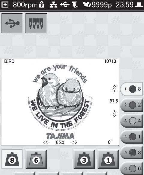
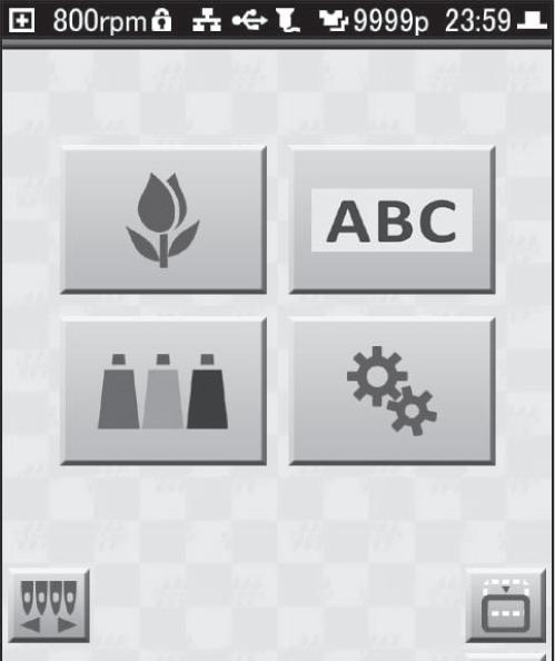
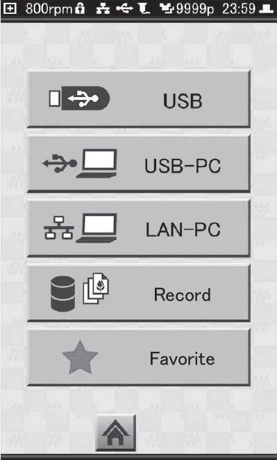
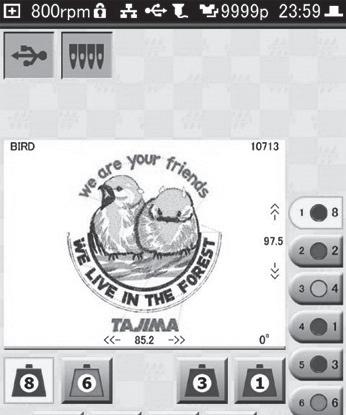
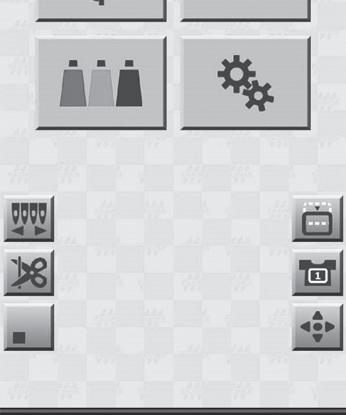
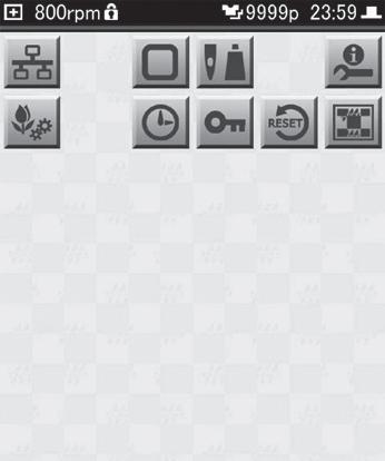
After the power switch is turned ON, the following Home screen appears on the operation panel.
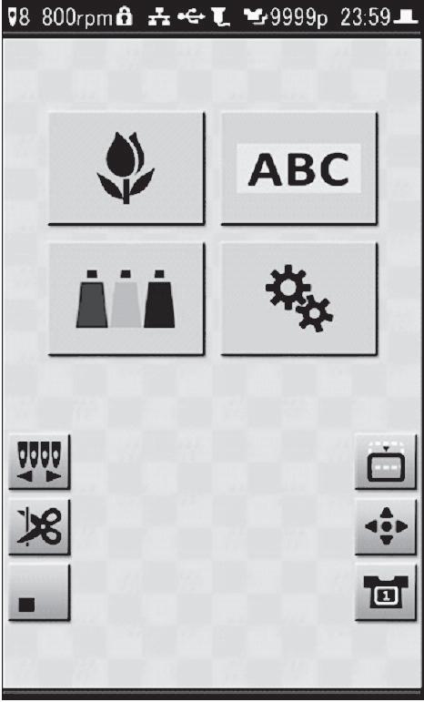
Indicates the sewing speed. The lock symbol is shown for design data that has speed limitations.


3Shown when the PC and machine are connected over the network.
4Shown when a USB memory is connected to the machine.
5Shown when a barcode reader is connected to the machine.
6Displays the number of completed runs for the current design.
7Displays the current time.
8Shown when the main shaft of the machine has stopped at the normal position.
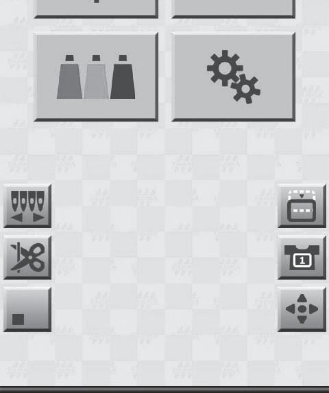
9Selects a design data for embroidery.
10Sets the thread colors.
11Make the settings for lettering embroidery.
12Make various settings for the machine.
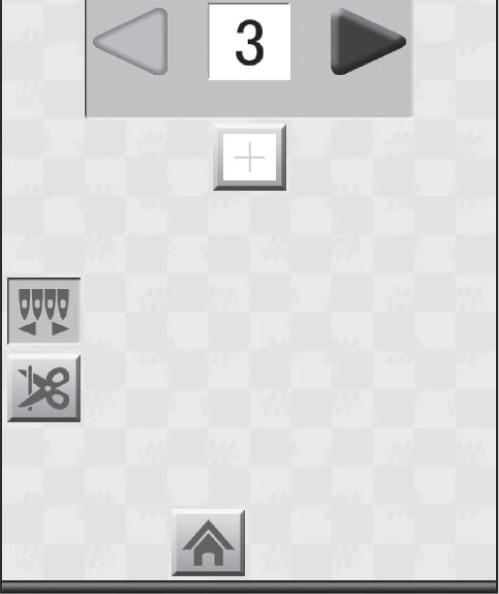
13Make manual color changes.
14Cut thread manually.
15Switches between display/hiding of icons.

16Move the frame to the front of machine.
17Manually move the frame.
18Sets the type of frame.
The operation panel is a touch screen. To switch among screens, make settings, etc., simply tap the icons displayed on the touch screen with your finger or the stylus packed with the machine.
There are a number of icons that are used in common throughout the various screens of the operation panel. Their purpose is the same on every panel. When an icon is selected, or when a setting is ready to be changed, it is highlighted in yellow.
Icon Description
Go back one screen
Go to Home screen
Confirm setting
Go to next page
Go to previous page
Before you start using the machine, prepare the needles, thread, and the fabric on which the embroidery is to be performed.
Before you start embroidering, check the condition of the needles, and if any of them are bent or broken, replace them with new needles following the procedure below. You will also need to change to needles appropriate for the type of fabric to be embroidered or the type of upper thread.
Caution
Always turn off the machine's power switch before you replace any needles. If needles are not secured properly, the thread may break or the needles may bend or break, making it impossible to carry out embroidery correctly.
Use needles designed to be used in embroidery machines. (Recommended: DB × K5Z1 [No. 9 through 14] made by ORGAN NEEDLE CO., LTD.)
For information on appropriate combinations of fabric, thread, and needles, see: "8.1 Producing beautiful embroidery".
1. Open the needle base cover. While holding the needle, use the flat head screwdriver (3 × 75) to loosen the screw, and then remove the needle.
2. Insert a new needle all the way into the needle bar, until you feel it make contact.
3. Position the needle so its groove faces forward, then tighten the screw to secure it.
4. Close the needle base cover.
The following illustration shows the places through which the upper threads for each needle should be passed. Carefully thread each upper thread, making sure that its path is correct at each position. The numbers that appear in the illustration below correspond to the needle numbers.
When threading the upper thread, open the needle base cover.
When using a thread spool with a small core, remove the thread stand blade.
When using metallic threads (gold or silver threads) or threads with high tensile strength, spool nets (Accessory part) should be placed over the spools. By using spool nets, you can help prevent thread snarling. If the spool net is too long, fold it back so it is better matched to the size of the spool.
2. Lift up the thread pressing shaft.
3. Hook the upper thread onto the tip of the upper thread guide (Accessory part), and insert it into the thread tube. Continue inserting until the threader comes out from the thread tube opening that is fixed in the tension base.
4. Once the upper thread has come through the thread tube opening, thread it as shown in the illustration to the right.
5. As illustrated to the right, pass the upper thread through the thread guide, and then pass it around the Rotary Tension disk.
An arrow, which shows the direction in which the upper thread should travel, is imprinted around the Rotary Tension disk. Follow this arrow when threading the upper thread.
6. As illustrated to the right, place the upper thread on the center thread course of the needle bar case, and then thread it through the hole at the top.
7. As illustrated at the right, open the needle base cover, and then thread the upper thread through the eye of the needle.
If using a threader (Accessory part), pass the thread through the needle eye as shown below.
8. Replace the thread pressing shaft and press it down until it clicks into place.
Initially, only the bobbin case is installed in the rotary hook and you will need to install a bobbin before running the machine. First, take the bobbin case out of the rotary hook. Then, after winding the under thread onto the bobbin, place it in the bobbin case.
Caution
Make sure to turn off the power switch before you take out or insert the bobbin case.
1. Open the Rotary Hook Cover.
2. While holding the latch lever of the bobbin case, remove the bobbin case from the rotary hook.
1. While positioning the bobbin so its thread winding direction is clockwise, insert it into the bobbin case, from the right side.
If the thread winding direction is reversed, abnormalities in the embroidery will occur.
2. Holding the end of the thread, guide the under thread through the slit (1) in the bobbin case.
3. Guide the under thread to the spring edge (2).
4. Adjust the tension of the under thread. Suspend the bobbin case by holding the end of the thread, and swing it back and forth. If the under thread comes out slowly, it means that the tension is set to the appropriate amount.
If an adjustment is necessary, turn the thread tension adjustment screw using a flat head screwdriver used for adjusting bobbin case tension.
5. Wrap the under thread twice around the pig tail.
1. Pull out about 5 cm length of under thread from the bobbin case.
2. Place the bobbin case inside the rotary hook and listen for it to click.
Let the under thread hang loosely in front of the bobbin case.
3. Close the Rotary Hook Cover.
In order to ensure that the embroidery finish will look good, it is important to correctly stretch out the fabric over the embroidery frame.
To carry out this work, the embroidery frame should be placed on a table or other level surface.
There are two sizes of embroidery frames available, one large, one small. Select the appropriate one to use depending on the size of the design. Note that you must change the settings for the frame on the operation panel whenever you change the embroidery frame.
At the default setting, the machine is set to use [Tubular 1] (large embroidery frame providing an embroidery area that has length of 200 mm and a width of 300 mm).
1. Loosen the adjustment screw on the outer frame.
2. Position the fabric on top of the outer frame.
With highly stretchable fabrics, such as those used for Tshirts and knits, a sheet of non-woven material/paper or the like should be spread out underneath the fabric to suppress material puckering before mounting it on the frame.
3. Position the inner frame and press it in.
4. Loosely tighten the adjustment screw on the outer frame, and then smooth out the material within the frame to remove any looseness or wrinkles.
Stretch out the fabric only to the extent that none of its weave is disturbed in any way.
5. Tighten the adjustment screw on the outer frame.
In the following we will explain the steps you need to take to perform embroidery from start to finish. First, get needles, thread, and fabric ready. Then, follow along with this manual and perform the actual operations. That way, you should be able to easily learn the basic things you need to do to use the machine.
1. Insert the power plug of the AC adapter into the outlet.
2. Turn on the machine's power switch.
The machine starts up, and the Home screen is displayed on the operation panel.
Also, the [START] and [STOP] button on the operation panel will light up.

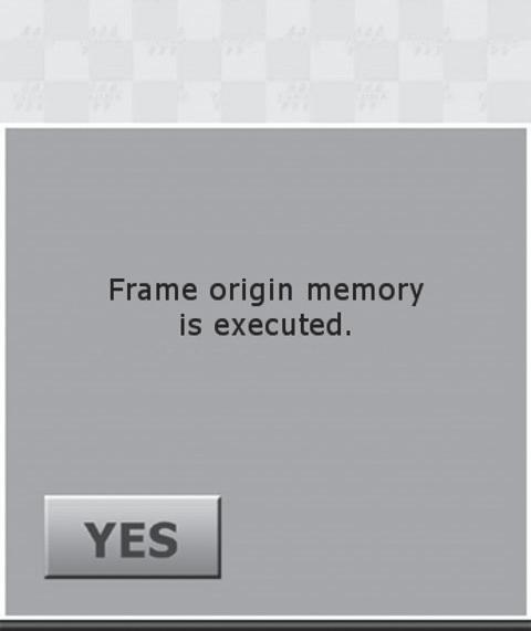
The Frame Origin Memory confirmation screen is displayed before the Home screen is displayed. Tap to memorize the frame origin.
Keep hands away from the area surrounding the frame and needle bar case while the frame origin is being memorized. Always wait until the next screen is displayed. Otherwise, there is a risk of injury due to the movement of the frame and needle bar case.
In order for the Frame Origin Memory screen to be displayed, the Frame Origin Memory setting needs to be enabled ([YES]).
"6.2.3 Memorizing the frame origin upon power up"
If an embroidery has been paused part way through, and the power has been cycled, the Paused screen is displayed instead of the Home screen.
1. Pick up the embroidery frame, and hold it so the inner frame is visible and faces upwards.
2. Push in the frame so that the arms on the right and left sides of the frame are engaged with the clips of the frame holder.
3. Push the embroidery frame in until the front edges of the frame holder's fixtures click into place in the holes at the front of the arms.
In the following, we will explain the steps you need to take before performing an embroidery.
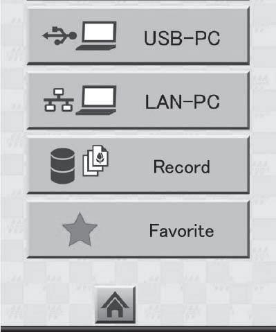
Using any of the following methods, load the design to be embroidered.
•Load from USB memory (USB flash drive)
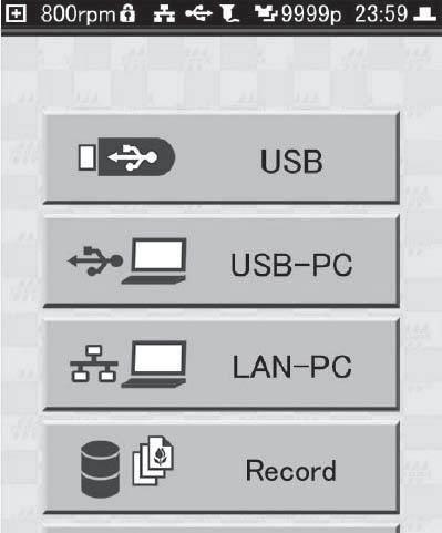
•Load from Record/Favorite
•Load from PC
Here, we will explain how a design can be loaded from a USB memory (USB flash drive). For other ways of loading designs: "4.3 Loading designs from records or favorites", "4.4 Loading a design from a PC"

1. Connect the USB memory (USB flash drive) to the USB port on the side of the operation panel.
Use USB 2.0 compatible devices formatted in the FAT/ FAT32 file system.
Be aware that some USB memory (USB flash drive) cannot be used due to slight differences in specifications.
Caution
Never remove a USB memory (USB flash drive) while designs are being read from it. Failure to observe this could result in damage to the USB memory (USB flash drive) or to the internal data of the machine.
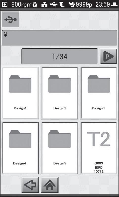
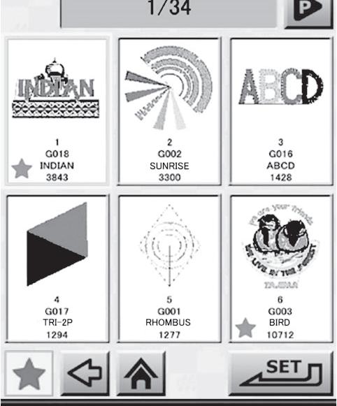
4. Tap a folder to select designs that are contained in the folder.

The root folder and three levels of subfolders of the USB memory (USB flash drive) are loaded. Up to 255 designs contained in a folder can be displayed in the List screen.
Root folder
Subfolder (first level)
Subfolder (second level)
Subfolder (third level)
Tap to switch pages.
The design-load source is displayed in the upper-left corner of the screen.
USB memory (USB flash drive) / LAN / Record /Favorite
5. Tap the design to be embroidered.
Reduced-size images (thumbnails) of designs that have been loaded from Record or Favorite, or from a PC via the LAN are displayed in the design list.
An icon labeled with one of the following data types is shown in the design list for designs that have been loaded from USB memory (USB flash drive).

•T: DST format
•T2: TBF format
•T3: TCF format
•B: DSB format
•Z: DSZ format
•U: U code format
When a design is loaded from USB memory (USB flash drive), a reduced-size image (thumbnail) of the design is displayed after the design is selected.

6. Tap .
If there are stitches that are too small in the design, the "Ok to delete tiny stitches" confirmation screen is displayed. To eliminate them, tap ; to cancel, tap .
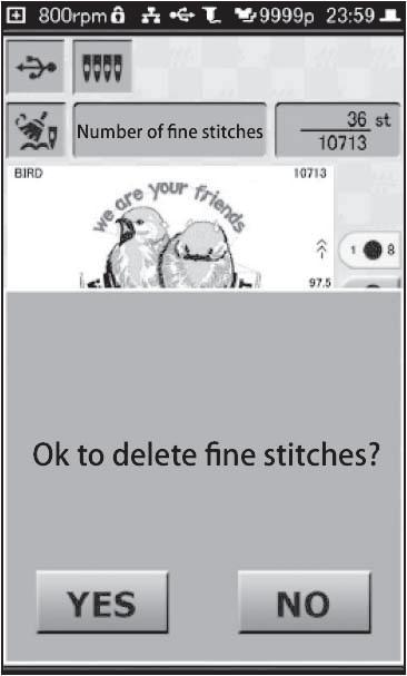
In order to display the tiny stitch deletion screen, the Cleanup setting needs to be enabled ([YES]).

"6.3.2 Eliminating tiny stitches"
An error screen (225) is displayed if the size of the design is too large, and exceeds the range within which embroidery can be carried out. In such cases, tap [RESET], and change the design to one which will fit within the range that can be embroidered. Also, check to make sure that the frame type is correct.
"6.2 Frame settings"
With some designs, the thread color and needle number for each step (order, for each color, in which embroidery is to take place) are already assigned in the design. Even without changing the settings for steps, for each step in the design, the upper thread of the color that you want to embroider can be set for the set needle No., allowing embroidery to take place using the correct color order. Also, even if steps are stored in the design, the needle number of the upper thread actually used in the embroidery can be changed. Additionally, when you want to use a design that has no steps assigned to it, you can set the appropriate needle numbers and then carry out embroidery. Here, we will explain the procedure for changing the needle No. of a step.
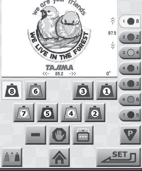
If a design that does not have steps assigned within it is loaded, all of the steps from needle No. 1 to No. 8 are assigned, in order.
For details on setting steps: "4.6 Editing the steps of a design"
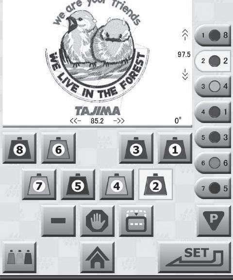
1. On the Needle No. Setting screen, tap the icon for the first step.
2. Tap the needle No. (1 to 8) that has the thread of the color that you want to assign to step 1.
3. Repeat steps 1 and 2 until all steps have a needle number assigned to them.
4. Tap .
The Frame Type confirmation screen is displayed. This sets the embroidery frame that is to be used.
In order for the Frame Type Confirmation screen to be displayed, the Frame Type Confirmation setting needs to be enabled ([YES]).

"6.2.7 Confirming the frame type before moving the frame to the design start point"
After tapping and a start point has been stored, a screen asking to confirm the move to the start point is displayed.
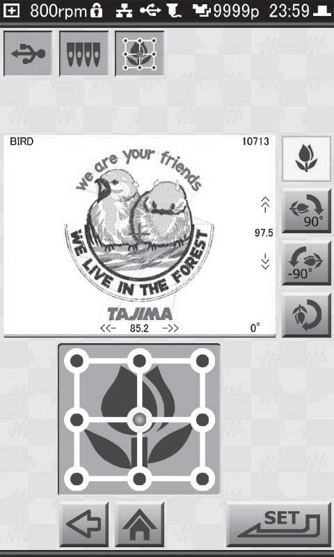
Here's how to set the orientation of the design and the embroidery start point.
1. Select the orientation of the design.
•To leave it in the original position:
•To rotate it 90° clockwise:
•To rotate it 90° counterclockwise:
•To rotate it 180°:
The preview of the design display and the tulip rotate to reflect the direction of rotation angle that was selected.
When embroidering a cap (as a finished product) using cap frame, select (180°). This is because, when using a cap, it is mounted upside down on the machine. When you are using a design that has already been rotated, there's no need to change the orientation of the design.
2. Tap the position for starting the embroidery from among the 9 points indicated in the design preview. The specified position is displayed in red.
You should try to select a place for the start position that allows for easy alignment of the frame.
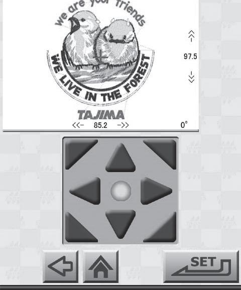
3.
The Frame Position Setting screen is displayed.


Manually, move the frame to the embroidery start point.
Caution
Keep hands away from the area surrounding the frame. Otherwise, there is a risk of injury due to the movement of the frame.
If you move the needle bar case to the position of the laser crosshair marker, you'll be able to see the place where the needle will descend. This makes it easier to decide on the start position for the embroidery.
"4.11 Using the laser crosshair marker"
1. Using the frame travel keys , move the frame to the embroidery start position. Tap the arrow icons you need to move the frame in the desired direction.
With each press of the center button of the frame travel keys , the speed of frame movement is toggled between high speed and low speed. Also, the color of the button changes as follows.
•High-speed: green
•Low-speed: gray

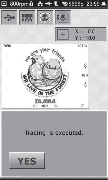
2. Once the start point for the embroidery has been determined, tap . The Trace screen is displayed.
In order for the Trace screen to be displayed, the Forced Trace setting needs to be enabled ([YES]).
"6.2.6 Performing trace after moving the frame to the design start point"
When the Forced Trace setting is disabled ([NO]), the Embroidery Start screen is displayed.
"3.3.7 Starting the embroidery"
By using the trace function, which moves the frame in accordance with the contour of the design, you can find out whether the embroidery design is appropriate or not, and whether the allowable area for embroidery will be exceeded or not.
Keep hands away from the area surrounding the frame and needle bar case while the trace is being carried out. Otherwise, there is a risk of injury due to the movement of the frame and needle bar case.
The laser crosshair marker lights, the frame moves in accordance with the contour of the design, and traces the path shown to the right.
While the trace is in progress, an hourglass is displayed on the screen. This indication disappears when the trace is completed.
If the needle position is not at the position of the laser crosshair marker before the trace is started, the needle position moves to the position of the laser crosshair marker first, and after that, the trace starts.
If you want to change the embroidery position, use the icon to display the frame travel keys, and then move the frame.

To pause a trace while it is in progress, press the [STOP] button on the operation panel. To continue the trace, tap in the confirmation screen; to cancel it, tap .
After the trace is completed, the start message screen is displayed if a start message has been set for the design.
If the design will not fit in the frame, an error screen (225) is displayed. Tap [RESET], and use the icon to display the frame travel keys, and then move the frame.
The sewing speed can be set to any value between 250 rpm and 800 rpm in 10 rpm increments.
The default setting is 800 rpm. The speed can also be changed when the machine is paused while an embroidery is in progress. If a start message has been set for the design, tap [RESET] to close the start message screen. After that, perform the operation.
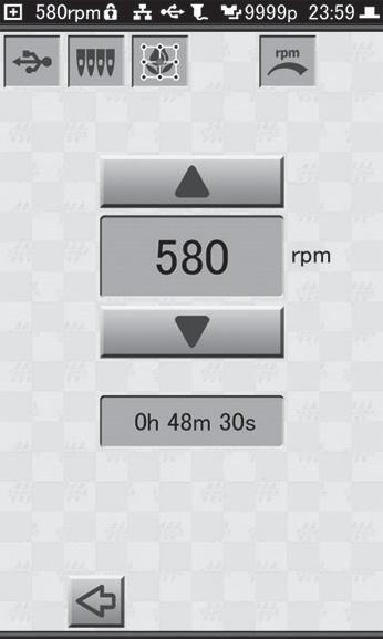
Speed Setting screen is displayed.

•To raise speed in 10 rpm increments:

•To lower speed in 10 rpm increments:
A general estimate of the amount of time it will take to complete the embroidery is shown in the screen. The embroidery time changes depending on the selected sewing speed.
You will be returned to the Embroidery Start screen.
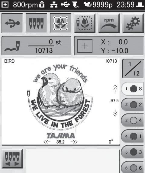
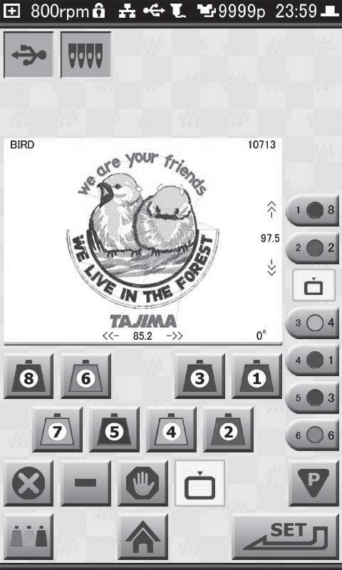
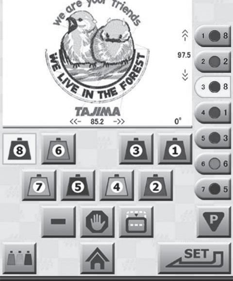
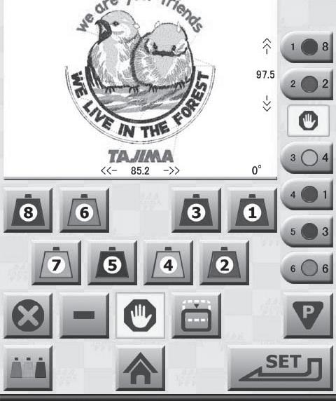
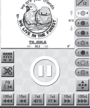
The following explains each item on the Embroidery Start screen.
1
The panel moves to the Trace screen, and trace is performed.
"3.3.5 Confirming that the design fits within the embroidery area" 2 Opens the Sewing Speed Setting screen.


"3.3.6 Selecting the speed"
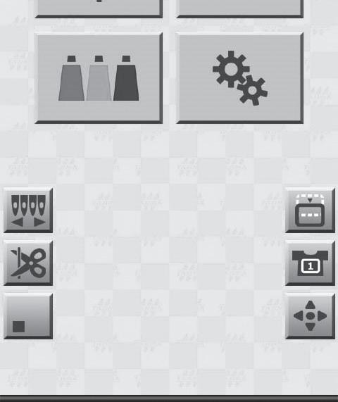
Opens the Setting screen.
Tap on the Setting screen, and the Embroidery Setting screen is displayed.
"6.1 Adjusting the embroidery settings"
Tap on the Setting screen, and the Info/Maintenance Setting screen is displayed.
"6.6 Setting the language used for display on the operation panel", "6.7 Displaying information about the machine"
4
5
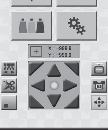
The number of stitches in the design is displayed as the sewn design stitch count and the total stitch count.
The current frame coordinates are displayed. To display frame coordinates correctly, the frame origin needs to be stored in memory.
"6.2.2 Memorizing the frame origin"
Keep hands away from the needle base and the area surrounding the frame while embroidery is in progress. Otherwise, there is a risk of injury.
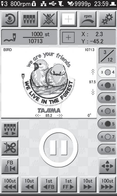
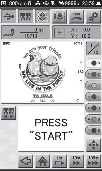
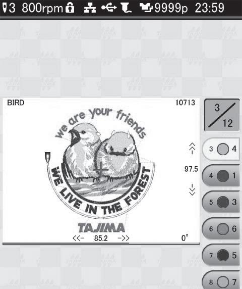
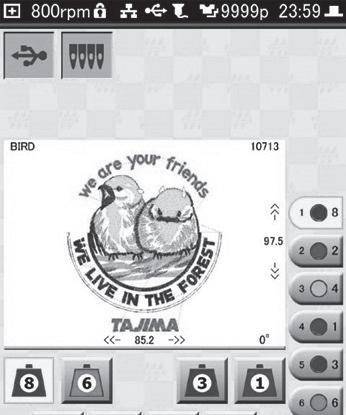
1. While the Embroidery Start screen is displayed, press the [START] button on the operation panel. The embroidery starts.
An image of the design is displayed on the operation panel, and the current position of the needle is indicated with a marker. Also, areas where embroidery has been completed are shown in gray.
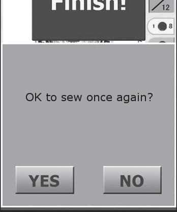
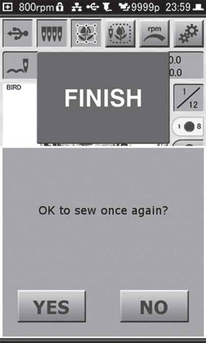
When the embroidery is finished, the Embroidery Complete screen is displayed.
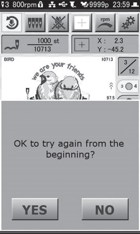
2. To finish with the embroidery, tap . To embroider the same design again, tap . If you tapped , the Embroidery Start screen is displayed.
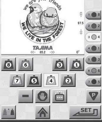
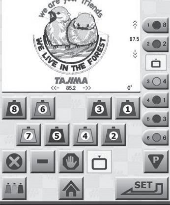
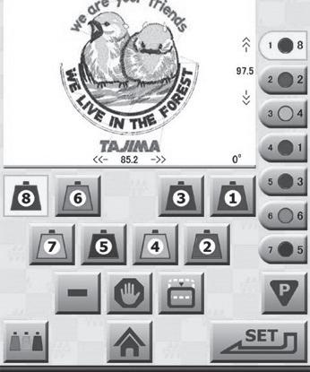
While embroidery is in progress, the machine can be paused.
1. Press the [STOP] button on the operation panel while embroidery is in progress. The machine stops and the Paused screen is displayed.

The following explains items not displayed on the Embroidery Start screen.
1234
Thread is trimmed automatically, and embroidery is stopped. Returns to the Embroidery Start screen.


Opens the Needle No. Setting screen.
"4.6 Editing the steps of a design"
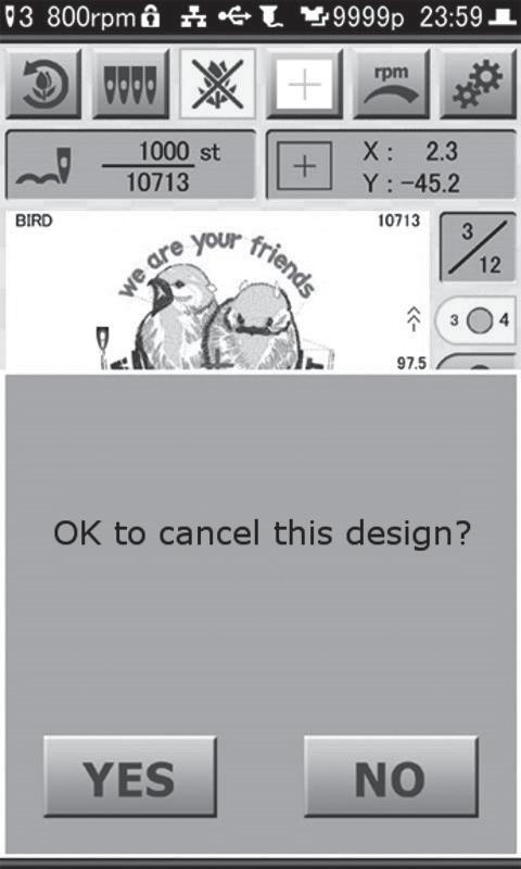
Thread is trimmed automatically, and embroidery is stopped. Returns to the Home screen.
The needle bar case moves to the position of the laser crosshair marker and the laser crosshair marker lights.

Resuming embroidery
Press the [START] button on the operation panel. Embroidery resumes from the paused position.

Starting the embroidery again from the beginning
Tap , and then tap .
Thread is trimmed automatically, and embroidery is stopped. Also, you are returned to the Embroidery Start screen.
Ending the embroidery
Tap , and then tap .
Thread is trimmed automatically, and embroidery is stopped. And, you are returned to the Home screen.

When thread breakage is detected, the machine stops automatically and an error is displayed. You should deal with this in the following methods, depending on the content of the error.
When "Upper Thread Break" (291) is displayed. Re-thread the upper thread through the needle.
When "Bobbin Thread Break" (293) is displayed. Take the bobbin case out of the rotary hook, and check the condition of the under thread. If the under thread is not threaded properly in the bobbin case, correct this by re-threading it. Also, if there is no longer any bobbin thread, or if there isn't much thread left, replace the bobbin.
"2.3 Setting the under thread"
Once the thread breakage issue has been dealt with, press the [START] button on the operation panel. Embroidery will resume.
Repair stitching can be carried out at the place where the thread broke by reversing/advancing the frame using and at the bottom of the Paused screen.
"4.9 Returning frame/advancing frame according to design"


1. While lifting the front of the frame, remove the frame from the machine's frame holder.
2. Remove the inner frame.
3. Remove the fabric.
If the under thread is appearing on the front of the fabric, you should lower the thread tension of the upper thread. Also, if the tightness of the upper thread stitching is deficient, you should raise the thread tension.
Refer to the following illustration, which shows a view of the fabric from the side, and check that the thread tension is appropriate.
Upper thread
Under thread Fabric
CorrectIncorrect
Under thread does not appear on the front of the fabric (Upper thread is appropriately tight)
Under thread appears on the front of the fabric (Upper thread tension is too tight)
Tightness of the upper thread stitching is deficient (Upper thread tension is too loose)
Turn the thread tension dial upwards to increase the tension of the upper thread. The scale indicator moves to the right.
Turn the thread tension dial downwards to decrease the tension of the upper thread. The scale indicator moves to the left.
To check the tension of the upper thread, the thread lock needs to be in the open position as shown below. It cannot be checked properly if the thread lock is not open.
1. Turn off the machine's power switch.
2. Pull out the power plug from the outlet.
Caution
When you need to cycle power to the machine, turn off the power, wait at least 5 seconds or more, then turn it back on.
Your machine offers a variety of convenient functions. For example, you can easily search for designs that have been used before, you can edit the embroidery steps, and you can carry out embroidery mending.

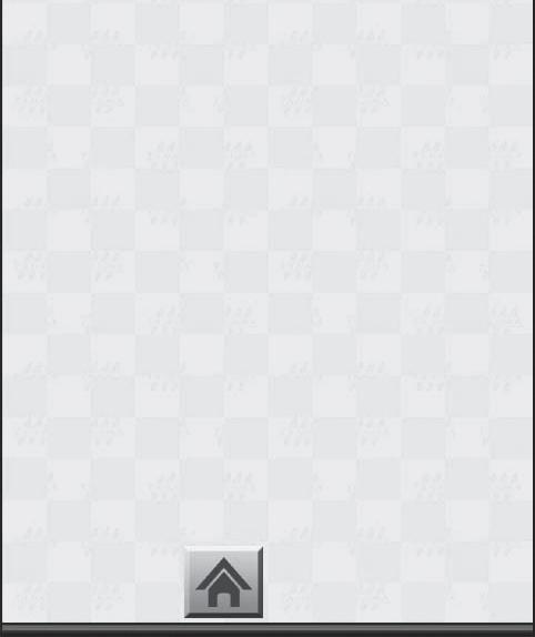
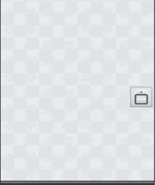
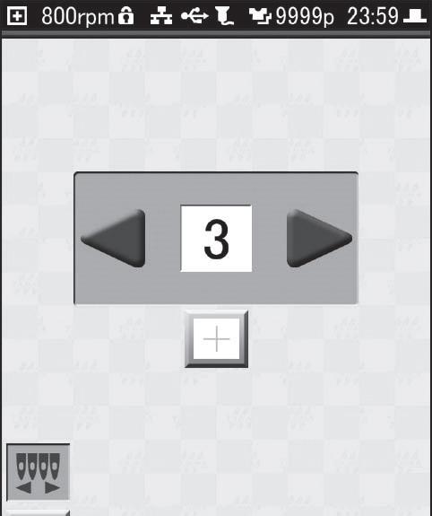
Here's how to set the machine so that only the wallpaper is shown on its display. This setting can be conveniently used to prevent inadvertent operations.
1. Tap on the Home screen. The Home screen is no longer displayed, and is displayed.

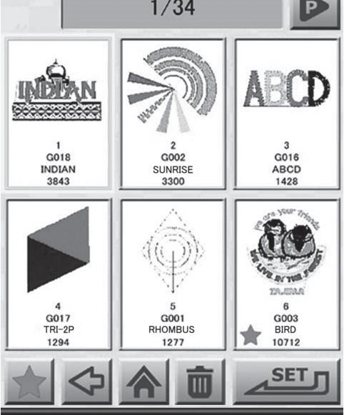
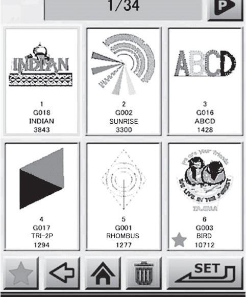
From the Record screen, designs you've used before can be stored in the Record. By storing a design that you use frequently, it can conveniently be called up the next time you want to use it.

How to store a design as a favorite
1. Tap on the Home screen. The Design Load screen is displayed.
2. Tap . The Design List screen is displayed.
is displayed only when the Record contains something. It is not displayed when embroidering for the first time.
3. Select the design you want to store in the favorites, and then tap .
The selected design is stored in the favorites, and is displayed in the lower left corner of the design.

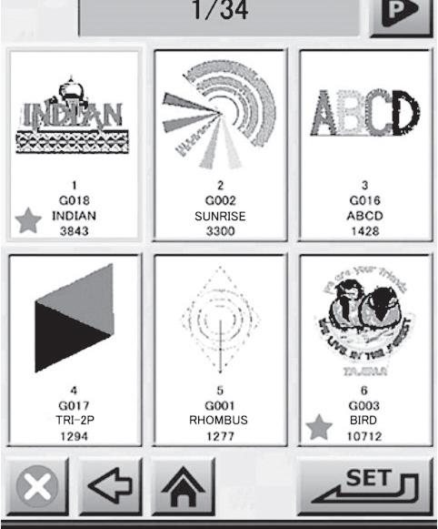
1. Tap or on the Design Load screen. The Design List screen is displayed.
2. Tap the design you want to remove from the favorites.

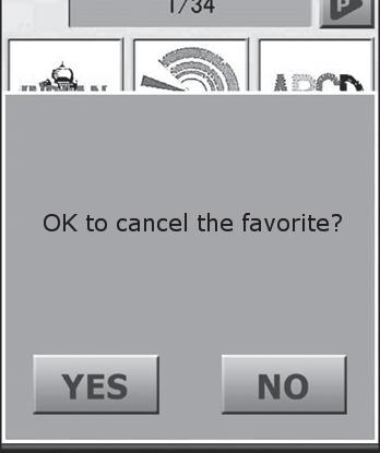

3. Tap .
The confirmation screen is displayed.
4. Tap .
The selected design is removed from the favorites, and the in the lower left corner of the design disappears. If is tapped while in the Favorite List screen, the design disappears from the List screen.
Designs that have been loaded before, and designs that have been stored in the favorites can be selected from Record or Favorite, and then used to perform embroidery.
Once a design has been loaded, it is stored in Record. Up to 200 designs can be stored in Record. If the 200 design limit is exceeded, designs will be erased, with the oldest being erased first. To delete a design from the Record, select the design to be deleted,and then tap . However, a design that is stored in the favorites cannot be deleted from the record. After it has been removed from the favorites, it can be deleted.
1. Tap on the Home screen. The Design Load screen is displayed.
2. Tap or . The Design List screen is displayed.
"4.2 Storing a design as a favorite or removing it" is displayed only when the Record contains something. It is not displayed when embroidering for the first time.
3. Select the design to be embroidered, and then tap
The selected design is loaded, and the Needle No. Setting screen is displayed. Next, you should perform the steps that need to be carried out before you can start an embroidery, such as setting the needle numbers and the embroidery start point.
"3.3.2 Setting the needle number" and related sections thereafter
When a design is loaded from Record, a confirmation screen is displayed if the thread colors of the design are different from the current thread color settings. Tap [RESET], and then change the thread color settings as necessary.
"4.7 Setting the thread colors"
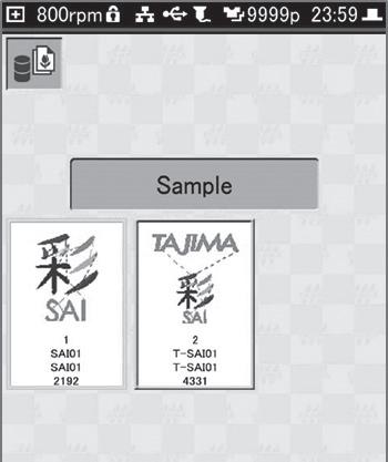
Record contains two sample designs that can be used for a test sewing. To sew a sample, tap Sample Folder in the Design List screen of History, and select a design.

Designs can be loaded from a PC using either of the following two methods.
•Load designs using a LAN cable
•Load designs using a USB cable
Designs from the dedicated design creation software or a separately available DG product on a PC can be loaded into the machine after it has been connected to the PC using a LAN cable.
If you want to directly connect the PC to the machine, you will need to prepare a commercially available cross-cable.
If connecting the machine to a network (router or hub), prepare a commercially available straight cable.
Network information for the machine needs to be set beforehand.
"6.4 Performing network settings"
1. Turn off the machine's power switch.
2. Connect the LAN cable to the PC's LAN port, or to the LAN port on the router or hub.
3. Connect the LAN cable to the LAN port on the right side of the machine.
4. Start up the PC, and then start up the design creation software.
5. Turn on the machine's power switch.
6. Tap on the Home screen. The Design Load screen is displayed.
7. Using the design creation software, send the design to the machine. For information on how to use the design creation software, refer to the manual for the design creation software.
8. Tap .
The Design List screen is displayed, select the design to be loaded.
Next, perform the steps that need to be carried out before you can start embroidery, such as setting the needle numbers and the embroidery start point.
"3.3.2 Setting the needle number" and related sections thereafter
When the network is set to YES(Auto), designs sent by the PC are loaded automatically, without the Design List screen being displayed. After this, operations can be carried out from the Trace screen.
"3.3.5 Confirming that the design fits within the embroidery area"

Designs stored in a PC can be loaded into the machine after a USB cable has been connected.
Caution
Never turn off the machine's power while it is operating. If you turn off the machine's power, all of the designs stored in the dedicated SAI drive will be erased. Prepare a commercially available USB cable (A to B). Use a Windows PC (7/8/8.1/10).

1. Turn off the machine's power switch.
2. Connect the type B connector of the USB cable to the USB port (type B, lower one) on the right side of the machine.
3. Start up the PC, and then connect the type A connector of the USB cable to the PC.
4. Turn on the machine's power switch.
5. Open Explorer on the PC. A dedicated SAI drive is created, and is displayed.
6. Click , and then save the design to the dedicated SAI drive at the lowest level.

7. Tap on the home screen. The Design Load screen is displayed.
8. Tap .
A list of the designs saved to the dedicated SAI drive is displayed in the list screen. Select the design to be loaded. Next, you should make the settings for the needle No. and the embroidery start point, and perform the other steps that need to be carried out before you can start an embroidery.
"3.3.2 Setting the needle number"
Bar codes for designs, which have been printed using the dedicated design creation software or a separate DG product, can be read using a commercially available bar code reader and loaded into the machine.
Caution
To use a bar code reader, the dedicated design creation software or a separately available DG product is necessary. The PC needs to be connected to the machine using a LAN cable, and the network information for the machine needs to be set beforehand.
"4.4 Loading a design from a PC", "6.4 Performing network settings"
Only bar code readers that are compatible with CODE 39 can be used.
Make sure that only single-byte alphanumeric characters are used in the names of files to be read using a barcode reader. Note that all alphabetic characters in the file name will be converted to uppercase letters.
1. Connect the USB cable of the barcode reader to the USB port (type A, upper one) on the right side of the machine.
2. Send the design to the machine using the design creation software, and then print the bar code. For information on how to use the design creation software, refer to the manual for the design creation software.
3. Use a barcode reader to read the barcode that was printed in step 2. The design is loaded, and the Start Point Setting screen is displayed. Next, you should perform the other steps that need to be carried out before you can start an embroidery, such as deciding on the orientation of the design and setting the embroidery start point.
"3.3.3 Setting the orientation of the design and the start point" and related sections thereafter
With some designs, the thread color and needle number for each step (order, for each color, in which sewing is to take place) are already assigned to the design. The following explains the steps you need to take if you want to carry out embroidery using needle numbers different than those stored within the design.
The steps below should also be followed when you want to set the appropriate needle numbers for a design that did not have any steps assigned within it, and then perform embroidery.
Any of the following operations can be inserted between steps:
•Bring frame to the front
•Pause embroidery
•Repeat step
If you want to use the color information that is already stored, the procedures explained here are unnecessary.
1. Tap on the Home screen. The Design Load screen is displayed.
2. Tap the source from which you want to load a design, and then load the design. The Needle No. Setting screen is displayed.
If a design that does not have steps assigned within it is loaded, all of the steps from needle No. 1 to No. 8 are assigned, in order.
"3.3.1 Loading the design to be embroidered", "4.3 Loading designs from records or favorites", "4.4 Loading a design from a PC"

Displayed while setting thread colors and steps. If you've arrived at this screen from the Pause screen, this icon is not displayed.


3Displays the thread color and needle No.
4Removes the inserted operation.
5Displays the Thread Color Setting screen.
6Inserts a step repetition operation.
7Inserts a pause operation.
8Returns to the Home screen.
9Inserts a bring frame out operation.
* The content displayed for each part is as follows:
This is the needle No.
This is the step No.
This is the thread color assigned to the needle No.
No.
1. In the Needle No. Setting screen, tap the icon for the step for which you want to set the needle No.

The icon of the step that was tapped and the needle No. set for the step are highlighted in yellow.
2. Tap the needle No. (1 to 8) that carries the color of thread that you want to set for the step.
The needle No. is set to the step.
3. Repeat steps 1 and 2 until all steps have a needle number assigned to them.
4. Tap .
The step is set.
4.6.3Bringing the frame to the front
While embroidery work is in progress, the machine can be paused and the frame can be brought out to the front of the machine. This feature can be conveniently used at times when, for example, you need to place appliqué material on the fabric.
Caution
Keep hands away from the area surrounding the frame. Otherwise, there is a risk of injury due to the movement of the frame.
1. In the Needle No. Setting screen, tap the specific step where you would like to perform the frame out function.
The icon of the step that was tapped and the needle No. set for the step are highlighted in yellow.
2. Tap .
The frame out function is added immediately after the step that was selected in step 1.

To erase the frame out function, tap that was inserted to the step, and then tap .
The step is set.
While embroidery is in progress, the machine can be paused.
1. In the Needle No. Setting screen, tap one of the step icons to which the pause is to be added. The icon of the step that was tapped and the needle No. set for the step are highlighted in yellow.
A pause operation is added immediately after the step that was selected in step 1.
To erase the pause operation, tap that was added at the step, and then tap .

The step is set.
This function allows specific steps to be repeated. After the step repetition operation has been inserted, the step before that will be executed repeatedly.
1. On the Needle No. Setting screen, tap the icon for the step into which the step repetition is to be inserted. The icon of the step that was tapped and the needle No. set for the step are highlighted in yellow.
The step repetition operation is added immediately after the step that was selected in step 1.
To erase the step repetition operation, tap that was added at the step, and then tap .


The thread color can be set for each needle No. There are two ways of selecting thread colors. They can be selected from the database contained in the machine, or they can be selected from the color palette.
Setting method Description
Select from the database Selections from the database can be made for the thread's maker, name, code, and color.
Select from the color paletteThe thread's color can only be selected from the color palette.
The thread colors set here will be reflected in the design and needle numbers shown on the screen.
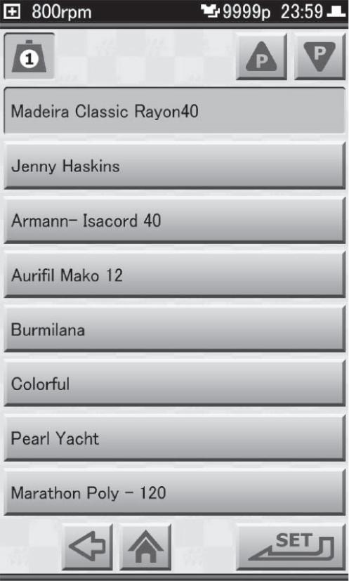
1. Tap on the Home screen. The List of Thread Color Setting screen is displayed.
2. Tap .
The Thread Maker Setting screen is displayed.
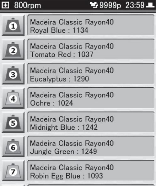
3. Select the name of the thread maker, and then tap
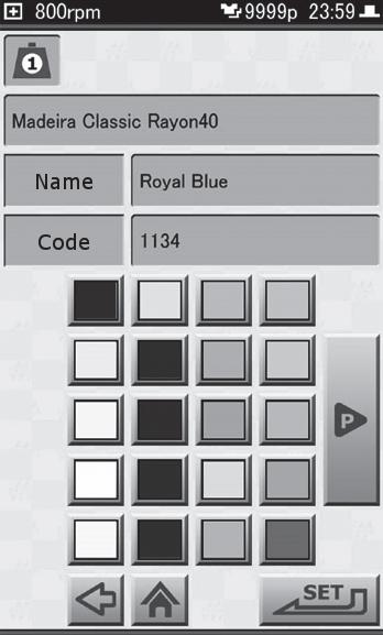
The Thread Color Setting screen is displayed.

4. Select the thread color, and then tap . Once the color has been selected, the [Name] and [Code] are displayed. You are returned to the List of Thread Color Setting screen.
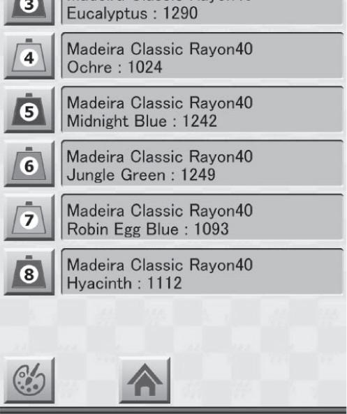
5. Repeat steps 2 through 4 until the maker and color have been set for all needles up to needle No. 8.
6. Tap .
You are returned to the List of Thread Color Setting screen.
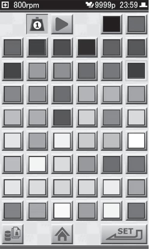
1. Tap on the Home screen. The List of Thread Color Setting screen is displayed.
2. Tap . The needle No. 1 Color Palette screen is displayed.
3. Select the thread color for needle No. 1, and then tap . The needle No. 2 Color Palette screen is displayed.


Tap in the lower-left part of the screen, and you are returned to the List of Thread Color Setting screen.
4. Repeat step 3 until the thread color has been set for all needles up to needle No. 8.
5. Tap . You are returned to the List of Thread Color Setting screen.
When the machine is stopped, the frame can be brought to the front quickly. This function can be conveniently used when you want to check the condition of the embroidery while it is being sewn, or when you want to change the frame.
Caution
If the frame is brought to the front while thread is still attached to the fabric, the thread could go slack. And, in such cases, when the embroidery is restarted, the slack in the thread could stick out from the fabric. Please trim the thread manually beforehand to prevent this.
"4.10.3 Trimming the thread manually"
Keep hands away from the area surrounding the frame. Otherwise, there is a risk of injury due to the movement of the frame.
1. Tap on the Home screen. The frame moves toward you. While the frame is moved out, is displayed in light red.

2. To return the frame, tap . The frame goes back to its original position, and the Home screen is displayed.
The frame can be returned or advanced according to the design data. This feature comes in handy in the following situations.
•When you want to do some repair stitching after the thread has broken, and you want to restart the embroidery from the position before the thread broke.
•When you want to start embroidering from a place or step part way through the design.
•When you want to skip embroidery of a place or step part way through the design.
Caution
Keep hands away from the area surrounding the frame. Otherwise, there is a risk of injury due to the movement of the frame.
1. Move the frame by tapping the icons below while in the Paused screen or the Embroidery Start screen.


•To go back 1 step:
•To go back 100 stitches at a time:
•To go back 10 stitches at a time:
•To go back 1 stitch at a time:
•To go forward 1 stitch at a time:
•To go forward 10 stitches at a time:
•To go forward 100 stitches at a time:
The frame can be returned one stitch at a time by pressing the [STOP] button on the operation panel while the machine is paused. If you press and hold the [STOP] button, the frame will consecutively return, one stitch at a time.
If , , or is tapped on the Embroidery Start screen, a screen asking you to confirm that you want to move the frame is displayed. Tap .
After the thread breaks, if you restart from a position where the stitches overlap slightly, the resulting product will look better.
1. Tap , and return the frame to a position where two or three stitches can overlap a place where the sewing was all right. With each tap of , the frame returns by one stitch.
2. Press the [START] button on the operation panel. The embroidery resumes from the position at which the frame was returned.
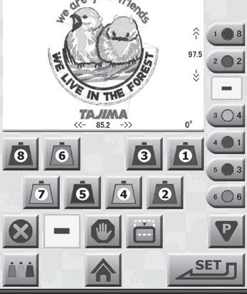
When the machine is stopped, movement of the frame, needle bar changes, and thread trimming can be performed manually.
The frame can be moved to any position you want. When the frame can be moved manually, is displayed on the screen.
Caution
If the frame is brought to the front while thread is still attached to the fabric, the thread could go slack. And, in such cases, when the embroidery is restarted, the slack in the thread could stick out from the fabric. Please trim the thread manually beforehand to prevent this.
"4.10.3 Trimming the thread manually"
Keep hands away from the area surrounding the frame. Otherwise, there is a risk of injury due to the movement of the frame.
1. Tap . (Example: In the case of the Home screen) The frame travel keys are displayed.
2. Press and hold the relevant arrow icon of the frame travel keys to move the frame to the position you want.


The frame stops when you release your finger from the arrow icon.
For details on the frame travel keys: "3.3.4 Moving the frame to the embroidery start point"
3. Tap to return to the Home screen.
The needle for the sewing start point can be changed by sliding the needle bar case. When the needle bar case can be operated manually, is displayed on the screen.
If the needle color is changed while thread is still attached to the fabric, the thread could go slack. And, in such cases, when the embroidery is restarted, the slack in the thread could stick out from the fabric. Please trim the thread manually beforehand to prevent this.
"4.10.3 Trimming the thread manually" Keep hands away from the area surrounding the needle bar case. Otherwise, there is a risk of injury due to the movement of the needle bar case.
The Manual Color Change screen is displayed. In the color change screen, the needle No. at the current sewing start position is displayed.
Tap , and the needle bar case moves to the position illuminated by the laser crosshair marker, and the is displayed on the screen.
With each tap of , the needle bar case slides. Also, the indication for the needle No. changes.


The thread can be trimmed manually. When the thread can be trimmed manually, is displayed on the screen.
Keep hands away from the area surrounding the needles and frame. Otherwise, there is a risk of injury when the needles come down and the frame moves.
1. Press and hold and release. (Example: In the case of the Manual Color Change screen)
Thread is trimmed. Also, while the thread is being trimmed, an hourglass is displayed on the screen.
The laser crosshair marker provides a cross-shaped laser illuminated area on the fabric, which indicates the position the needle will fall.
When lighted, the laser crosshair marker makes it easy to adjust positioning when the frame is moved, such as when moving the frame to a position to be embroidered.
The laser crosshair marker can be lighted from the Home screen, the Ready to Embroider screen and in the Embroidery Paused screen.

"1.2 Home screen", "3.3.7 Starting the embroidery", "3.3.8 Pausing the machine"
Caution
If the needle color is changed while thread is still attached to the fabric, the thread could go slack. And, in such cases, when the embroidery is restarted, the slack in the thread could stick out from the fabric. Please trim the thread manually beforehand to prevent this.
"4.10.3 Trimming the thread manually"
Keep hands away from the area surrounding the needle bar case. Otherwise, there is a risk of injury due to the movement of the needle bar case.
3.
The Color Change screen is displayed.
The needle bar case moves to the position of the laser crosshair marker. The laser crosshair marker lights up, and the place where the needle will fall is shown in the crosshairs.
Designs can be created on a PC using the dedicated design creation software or a separately available DG product.
Once a design is created, USB memory (USB flash drive) or the network functionality can be used to load the design into the machine, and use it for embroidery. Please contact your sales dealer for information on how to obtain the design creation software, how to install it, and how to use it.
Text such as initials or names can be embroidered using combinations of the fonts stored in the machine.
Designs created using the lettering embroidery function can consist of only one color. Textual embroidery designs that have been created are automatically given a file name when they are stored in Record.
After selecting a font, characters are entered to create the lettering design. Lettering designs, which have been embroidered at least once, are stored in the Record.
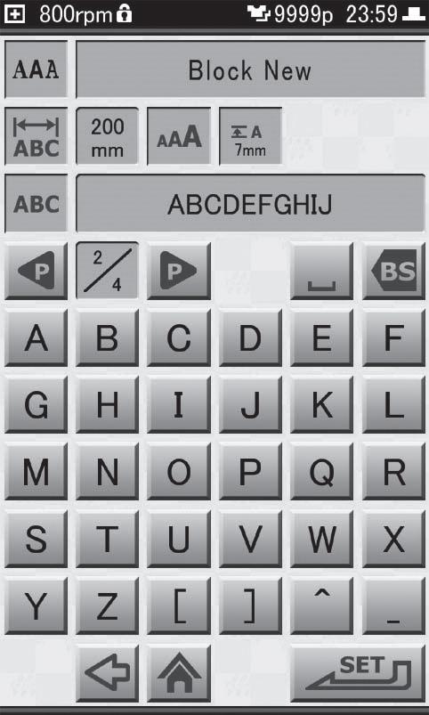
1. Select on the Home screen. The Font Selection screen is displayed.
2. Select the font to be used, and then tap . The Maximum Width of Text Setting screen is displayed.
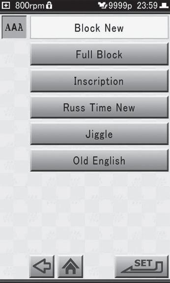
The fonts [ ひらがな ], and [ カタカナ ] are displayed only when the language of the operation panel is set to 日本 語 (Japanese).
3. Use to set the maximum width of the character string, and then tap . The Text Height Setting screen is displayed.
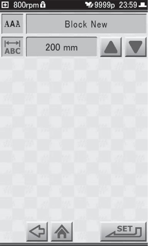
The maximum width of the character string can be set to any value from 5 to 300 mm.
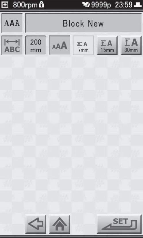
4. Select the character height, and then tap .
•To set character height to 7 mm:
•To set character height to 15 mm:


•To set character height to 30 mm:
When using the Jiggle or Old English character fonts, the available height for the characters is 25 mm, 50 mm, or 75 mm.
The Text Entry screen is displayed.
5. Enter the text to be embroidered, and then tap
If you want to enter numerals, special symbols, etc., tap the to switch pages.


To erase a character that has been entered, tap .

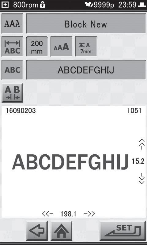
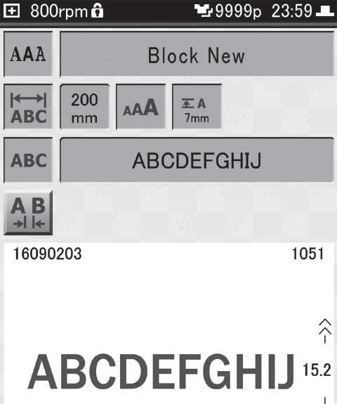
The Confirm Image screen is displayed.
•1: Name of design
•2: Image of design
•3: Horizontal width of set design (in mm units)
•4: Number of stitches in design
•5: Height of set design (in mm units)
The character spacing selection icons ([Whole] or [Part]) are displayed to the right of the icon.
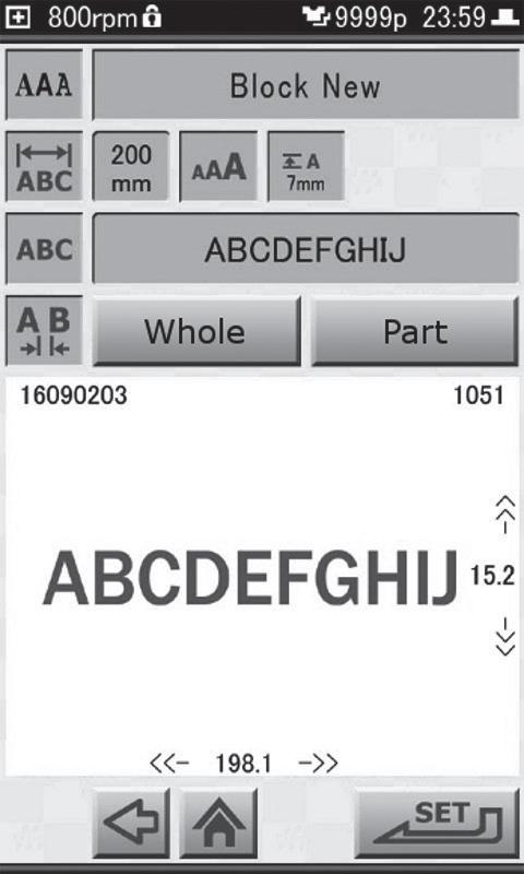

7. Select the character spacing, and then tap .
•To make spacing between the characters uniform: [Whole]
•To individually set space between characters: [Part]
The character spacing setting icons are displayed.
8. If [Part] was tapped in step 7, tap and select the two characters for which the spacing is to be set.
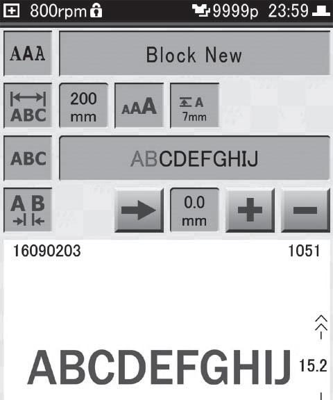
The character spacing can be set to any value from -50 to 100 mm. (The default setting is 0.5 mm.)
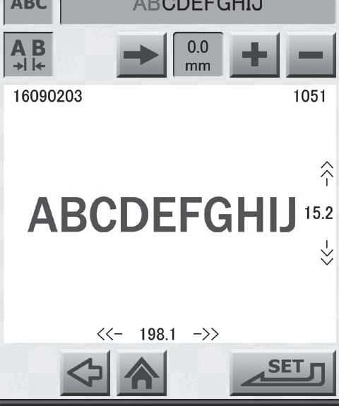
The two characters that were selected are displayed in red.
9. Using , set the character spacing. If [Part] was selected in step 7, repeat steps 8 and 9 to set the character spacing for any character positions that need adjustment.
If the maximum width of a character string is exceeded while setting the character spacing, an error screen is displayed. In such a case, tap [RESET] and change the character spacing.
10. After setting the character spacing, tap . The Needle No. Setting screen is displayed. Set the thread color and needle No.
Settings for the machine, such as those for the embroidery frame or those on how the machine is to be used, are explained in the following. Please refer to this chapter for the convenient settings, such as if you would like to adjust the settings of the network and frame movement, or change the wallpaper of the operation panel.
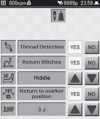
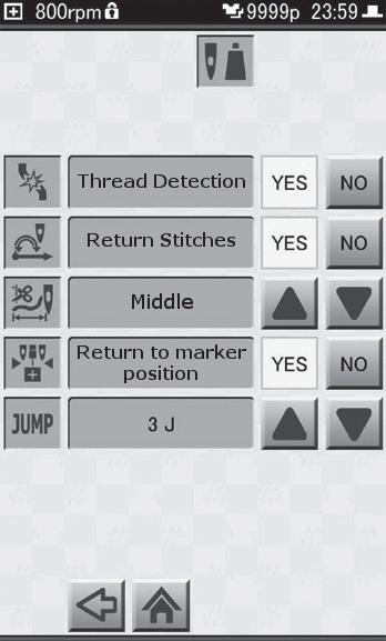
The chart below shows how the embroidery parameters are originally set. These settings can be changed as necessary.
Thread DetectionDetects any breakage in the upper/under thread.YES/NOYES
Return stitches
Length of upper thread to remain after trimming thread
Return to marker position
Determines whether to sew return stitches at the start of embroidery.
Length of upper thread to remain after thread is trimmed
Whether to move the needle bar case to the position of the laser crosshair marker when the embroidery is finished
Jump codeConditions governing thread trimming within a design[1J] to [9J]3J
Displaying the Embroidery Setting screen
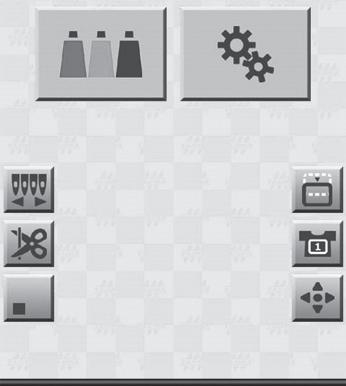
1. Tap on the Home screen. The Setting screen is displayed.

2. Tap . The Embroidery Setting screen is displayed.
3. Once the setting has been made, tap . You are returned to the Setting screen.
This setting specifies whether or not breakage of the upper thread or under thread is to be detected. When enabled, the machine will be stopped when thread breakage is detected. When disabled, the machine won't stop even if the thread breaks, and the embroidery will continue.
1. Display the Embroidery Setting screen.
2. Tap [YES] or [NO] for [Thread Detection].
•To detect thread breakage: [YES]
•To not detect thread breakage: [NO]
This setting determines whether or not return stitches are performed at the beginning of the embroidery.

When this setting is enabled, return stitches two times back and fourth are performed at the beginning of embroidery.
When return stitches are performed, problems at the beginning of the embroidery can be reduced. There will also be less chances for the thread to pull out.
Enable the setting for return stitches when the beginning stitches of a design are unstable.
Some designs are already set so return stitches are performed.
1. Display the Embroidery Setting screen.
2. Tap [YES] or [NO] for [Return Stitches].

•To perform return stitches: [YES]
•To not perform return stitches: [NO]
Select from the following to set the length of upper thread that remains after the thread is trimmed. Long, Middle (default setting), and Short are the 3 settings that can be selected from.
If the end of the upper thread is visible on the front of the embroidery in places where sewing started, set this to [Middle] or [Short].
If the thread does not link correctly where embroidery is started, and embroidery cannot be carried out properly, set this to [Long].
When metallic type threads such as gold or silver are used, setting this to [Long] can help stabilize the start of embroidery.
1. Display the Embroidery Setting screen.
2. Using of , change the setting.
This setting determines whether or not the needle bar case moves to the position of the laser crosshair marker after the design has been embroidered, and the laser crosshair marker lights. Having the laser crosshair marker light makes it easier to decide the position of the next design to be embroidered.
Caution
Before the laser crosshair marker lights, the needle bar case moves to the center position. Keep hands away from the needle bar case while it is moving. Otherwise, there is a risk of injury.
1. Display the Embroidery Setting screen.
2. Tap [YES] or [NO] for [Return to marker position].
•To move the needle bar case: [YES]
•To not move the needle bar case: [NO]
In some cases, the thread needs to be trimmed part way through a design. For example, between letters when the same needle No. is to be used for the letters. Whether or not the thread is to be trimmed can be set using the number of jump stitches (stitches where needle does not come down). At the default setting of [3J], the thread is automatically trimmed in places where jump stitches continue for 3 or more stitches.
1. Display the Embroidery Setting screen.
2. Using of , change the displayed setting.
•Trim the thread after these number of jump stitches: [1J] to [9J] (1 to 9 stitches)
•Thread is not to be trimmed: [NO]

The frame settings need to be modified according to the type of frame to be used.
Caution
If the settings are not suitable for the frame being used, the frame could come into contact with parts of the machine and cause damage to the frame or the machine itself. Make sure the setting matches the type of frame to be used.
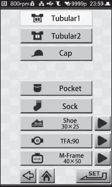
1. Tap on the Home screen. The Frame Type Selection screen is displayed.
2. Select the type of frame to be used.
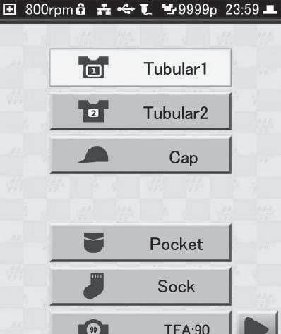
•When using the large-sized frame (200 × 300): [Tubular 1]
•When using the small-sized frame (100 × 100): [Tubular 2]
•When using the cap frame (optional): [Cap]
Please refer to the manual that came with the frame when you wish to use an optional frame other than the three listed above.
Whenever you change to a different type of frame, the frame origin needs to be memorized in the machine.
The "frame origin" refers to the absolute coordinate values (X: 0.0, Y: 0.0) that are used for reference when calculating the current position of the frame.
If the frame origin is incorrect, not only will the following problems occur, the needle or presser foot may also come into contact with the frame during embroidery, causing damage as a result.
•The frame coordinates are not displayed correctly.
•Discrepancies occur with regard to the permissible range of movement for the frame.
"6.2.4 Setting the permissible range of movement for the frame"
Caution
Do not place hands or anything else near the frame. Otherwise, there is a risk of injury due to the movement of the frame.
1. Tap on the Home screen. The Setting screen is displayed.

2. Tap .
The Frame Setting screen is displayed.
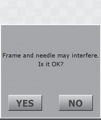
3. Tap . A confirmation message is displayed.


4. Tap .
The frame moves, and the process for memorizing the frame origin is carried out. Once the frame origin has been successfully memorized, you will be returned to the Frame Setting screen.
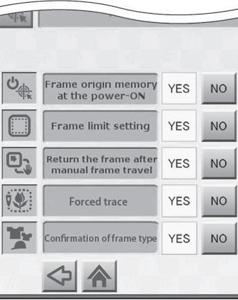
This setting determines whether or not a message related to memorizing the frame origin is displayed when the machine's power is turned on.
To be able to use this function, the frame limit setting needs to be enabled ([YES]).
"6.2.4 Setting the permissible range of movement for the frame"
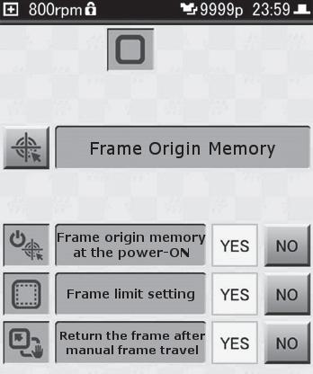
1. Tap on the Home screen. The Setting screen is displayed.
2. Tap . The Frame Setting screen is displayed.
3. Tap [YES] or [NO] for [Frame origin memory at the power-ON].
•To display a message concerning memorization of the frame origin when the machine is powered up: [YES] (default setting)
•To not display a message concerning memorization of the frame origin when the machine is powered up: [NO]
4. If [NO] was selected in step 3, a confirmation message is displayed, so tap . Once the setting has been completed, you will be returned to the Frame Setting screen.
This setting determines whether or not a permissible range of movement (frame limits) for the frame is to be set.
The machine is originally set so that the frame cannot be moved beyond the range inside the frame in which embroidery can be performed. This is in order to prevent needles or the presser foot from hitting the frame while embroidery is in progress.
When this setting is disabled ([NO]), the embroidery range can be extended to the maximum, up to the point immediately before the needle or presser foot might hit the frame.
With this setting disabled, the needle or presser foot may come into contact with the frame during embroidery, resulting in possible damages. Whenever possible, embroidery should be carried out with frame limits enabled ([YES]).
In order to make this setting, the frame origin needs to be correctly stored in memory.

"6.2.2 Memorizing the frame origin"
•To move the frame only within the area defined by the frame limits, and stop the embroidery whenever the frame limits are exceeded: [YES] (default setting)
•To have the frame not stop at the frame limits: [NO]
4. If [NO] was selected in step 3, a confirmation message is displayed, so tap .
Once a setting has been completed, you will be returned to the Frame Setting screen.

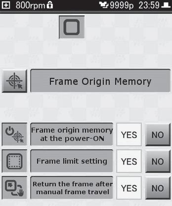
6.2.5Returning the frame to its original position after manually moving it
This setting determines whether or not the frame is to be moved back to the original point after it has been moved manually when the machine was stopped part way through a design.
In order to make this setting, the frame origin needs to be correctly stored in memory. "6.2.2 Memorizing the frame origin"
1. Tap on the Home screen. The Setting screen is displayed.
2. Tap . The Frame Setting screen is displayed.
3. Tap [YES] or [NO] for [Return the frame after manual frame travel].
•To have the frame move back to its original position after it has been moved manually, and then resume the embroidery: [YES] (default setting)
•To resume the embroidery from the current position of the frame, where it was moved to manually: [NO]
This setting determines whether or not the trace is to be performed after moving the frame to the design start point.
1. Tap on the Home screen. The Setting screen is displayed.
2. Tap . The Frame Setting screen is displayed.
3. Tap [YES] or [NO] for [Forced Trace].
•To perform trace after moving the frame to the embroidery start point: [YES] (default setting)
•Not to perform trace after moving the frame to the embroidery start point: [NO]
This determines whether or not the frame type is to be confirmed before moving the frame to the design start point.
1. Tap on the Home screen. The Setting screen is displayed.
2. Tap . The Frame Setting screen is displayed.
3. Tap [YES] or [NO] for [Confirm Frame Type].
•To confirm the frame type to be used before moving the frame to the design start point: [YES] (default setting)
•To skip confirmation of the frame type to used before moving the frame to the design start point: [NO]
6.3.1Setting to start operation automatically when the same needle number is selected for multiple steps
This setting determines whether or not to automatically pause the machine in between steps when a continuous series of steps are set to use the same needle No. When the machine is paused automatically, such pauses can be used to check the quality of the embroidery, or put in place appliqué material to be sewn.
3. Tap [YES] or [NO] for [Auto start at same color].
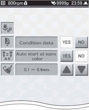

•To not stop the machine between steps set to use the same needle No., and to continue embroidering: [YES]
•To pause the machine between steps set to use the same needle No.: [NO]
This setting determines whether or not tiny stitches are to be eliminated (Cleanup) after a design has been loaded; it is set in terms of the stitch length. The default setting is [0.1 to 0.4 mm], which results in the cleanup of stitches having a length of from 0.1 to 0.4 mm.
1. Tap on the Home screen. The Setting screen is displayed.
2. Tap . The Design Setting screen is displayed.
3. Using of , change the displayed setting.

•To perform cleanup, set the length of the stitches to a value from [0.1 to 0.4 mm] to [0.1 to 0.9 mm]
•Not to perform cleanup: [NO]
Here's how to make the settings necessary for using a network. Once these settings have been made, you can connect a LAN cable and load designs from a PC.
To connect to a network, you will need to have a commercially available LAN cable and router or other network devices.
"4.4 Loading a design from a PC"
1. Tap on the Home screen. The Setting screen is displayed.
2. Tap . The Network Setting screen is displayed.
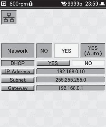
3. Tap [Network], then select how the network is to be used.
•To not use the network: [NO]
•To select designs sent by a PC in the Design List screen: [YES]
•To consecutively load designs that have been sent by a PC: [YES (Auto)]
4. Tap [DHCP], and then select [YES] or [NO].
•When using a DHCP server or router: [YES]
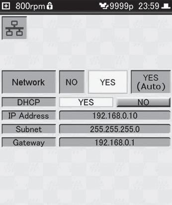
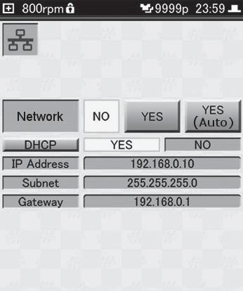
•When manually setting network addresses such as the IP address: [NO]

5. If [NO] was selected in step 4, tap [IP Address], [Subnet], [Gateway].
The numeric keypad is displayed.
6. Enter each address using the numeric keypad, and then tap .

The network address is set.
We recommend using the network address values that were set for the machine beforehand. If you want to change the network addresses, please consult with your sales dealer.
The default values for the addresses are as follows:
• [IP Address]: 192.168.0.10
• [Subnet]: 255.255.255.0
• [Gateway]: 192.168.0.1
Only IPV4 addresses are supported.
Tap , and the cursor moves to the upper or lower three digits.

When you continue on to enter other addresses, tap after each address has been entered to confirm it before moving to the next one.

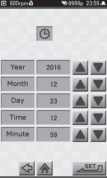
1. Tap on the Home screen. The Setting screen is displayed.
2. Tap . The Date/Time Setting screen is displayed.
3. Set the date and time using , and then tap . You are returned to the Setting screen.


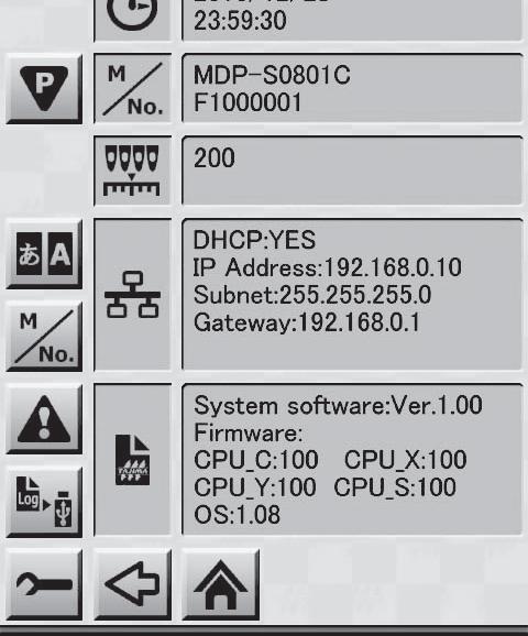
1. Tap on the Home screen. The Setting screen is displayed.
The Info/Maintenance Setting screen is displayed.
3.
The Language Setting screen is displayed.
The machine can be switched to use any of the following languages:
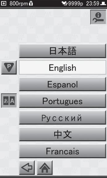
Japanese, English, Spanish, Portuguese, Russian, Chinese (simplified), French, German, Italian, Czech, Turkish, Hungarian, Thai, Vietnamese, Korean, Greek Tap , to switch the language page.
Tap to return to the previous screen, and the display language will change.
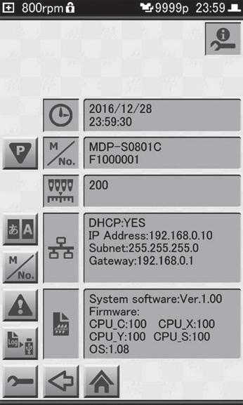
The current date and time, model name, and other information about the machine can be checked as follows:
1. Tap on the Home screen. The Setting screen is displayed.

2. Tap .
•The date and time currently set on the machine
•Upper row: model name; Lower row: machine number

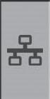


•Color change potentiometer value (numerical value of sensor that indicates needle position)
•Network settings of the machine
•Machine's software version information
•Machine operational time limit (only when Time-based Functional limit has been set)
•Machine library verision information
Tap or to switch pages.
The wallpaper color on the operation panel can be changed as follows. The current wallpaper is displayed in the Wallpaper Setting screen.
1. Tap on the Home screen. The Setting screen is displayed.

2. Tap . The Wallpaper Setting screen is displayed, and the current wallpaper is displayed.

3. Select the color of the wallpaper using , and then tap .

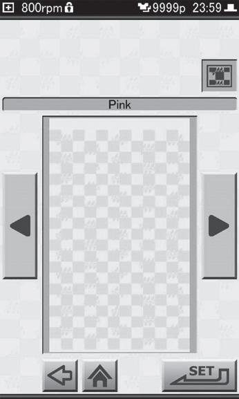
The wallpaper color can be selected from the following:
•Green
•Gray
•Pink
•Yellow
•Blue
You will be returned to the Setting screen.
The functions and settings below, which are not explained in this manual, were pre-set so as to assure the proper operation of the machine, and are used by service personnel when performing maintenance tasks.
Caution
Do not change these settings. Otherwise, there is a risk that the machine will fail to operate normally.

Icon Description


Machine Number Setting
Error Stack Display
Memory Backup

Maintenance (Press and hold for at least 3 seconds or more and release)
Maintenance—Return to the fixed position of main shaft
Maintenance—Motor Excitation
Maintenance—Touch panel compensation
A.S. after Auto Data Set
Input of Test Design
Password Setting
Startup Lock

Time-based Functional limit
Design Related Setting
Transfers the machine's parameters to the controller card
Usage of Condition Data Associated with Design
Parameter Settings Reset
Design Record and Error Stack Erasure
Factory Defaults Reset
By using the separately sold cap frame, you can embroider visored caps.
Caution
Please take note of the following things regarding use of a cap frame. When attaching the cap frame, do not remove the frame holder from the machine. Place an interlining cloth such as non-woven fabric under the cap when embroidering a cap.
Type and size
When using a cap frame, you can embroider visored caps. Do not use the following types of items, since the embroidered results will not be good, and it could lead to bent needles and the malfunction of the machine.
•Hats that are not of the cap type
•Hats made of fabric that tends to get wrinkled or stretches and contracts easily
•Hats that are of a size that won't fit in the cap frame (small hats or extremely shallow hats)
•Hats that have a visor that exceeds 80 mm in length Range within which embroidery can be carried out
When sewing designs using the cap frame, allow at least 15 mm distance from the stitching of the visor, and use only designs that will fit within the embroidery area shown below. Note, however, that even with a design that fits within the range below, it is possible that it cannot be embroidered, depending on the shape of the hat or its depth.
•Vertically: 75 mm or less
•Horizontally: 300 mm or less
Concerning needles
To prevent the breakage of needles or thread when embroidering caps, use No. 12 needles.
Caution
Switch the power off before starting the following procedure.
1. Slide the frame drive system (2) forward so that you can see the attaching bases (1) (two places, on the right and left) on the lower side of the frame drive system.
2. Loosely screw in the knobbed screws (3) (two places, on the right and left) to the attaching base (1) on the lower side of the frame drive system. The knobbed screw (3) should be tightened so as to slightly engage with the screw hole.
3. Attach the base of the ring shaft (5) at the place (4) for installing the ring shaft on the lower part of the bed, and fasten it with the screw using a Philips screwdriver.
4. Loosen the fastening screws (7) (four places) of the cap frame unit (6) using a Philips screwdriver.
This step (Step 4) needs to be carried out only the first time. As long as it will be mounted on the same machine, there's no need to repeat this procedure after the first time.
If it is to be mounted on a different machine, this procedure will need to be performed once again.
5. Position the center, cylindrical part (8) of the cap frame unit onto the ring shaft (9), and slide the cap frame unit (6) in, along the ring shaft (9).
6. Slide in the cap frame unit (6) until the unit cannot be pushed in any further. Then, fasten the knobbed screws (3) (two places, at right and left).
7. Tighten the screws (7) (four places) that were loosened in step (4).
8. Turn the cap frame unit (6) right and left, so the screw holes (10) in the frame drive system are lined up with the positions of the screw holes (11) in the cap frame unit (two places, on the right and left).
9. Insert the knobbed screws (12) into the screw holes at the frame drive system and fasten them. At this time, fasten the knobbed screws (12) in the status that the connecting sash (13) is slightly shifted to the front.
10. For the final confirmation, turn the cap frame unit (6) right and left to move the connecting sash to confirm that its movement is not heavy.
1. Install the cap frame gauge on a stable surface such as a table or stand, and use the clamp to fix it in place.
2. Place the cap frame over the circular part of the gauge.
3. Align the cutout portion of the cap frame with the position of the guide on the gauge and push in the cap frame. Keep pushing in until the lock levers (two places) click into place, and the cap frame is secured.
4. Remove the fastening band of the cap frame. Then, place some interlining cloth, such as non-woven fabric, on the surface of the holder of the cap frame.
5. Pull out the sweatband from the cap so it is on the outside.
6. Position the visor of the cap so it faces directly upwards, and insert the sweatband under the holder on the cap frame. Push the cap in until the visor reaches the forward edge of the holder. Also, adjust the positioning of the cap so that the center of its visor is aligned with the guide line.
7. Position the lid frame of the cap's visor, then fasten it with the latches.
If the lid frame is loose, or too tight, and the cap cannot be held in place using the latch, adjust the position of the latch holder.
8. Pull the fabric downward so that the portion to be embroidered is stretched out properly.
9. Smooth out the fabric of the cap, then secure it by attaching clips to the clip holders (two places).
10. Press the lock levers (two places) on the cap frame gauge, and then pull off the cap frame from the gauge.
1. While turning the visor of the cap to the right so it will not make contact with the machine, insert the cap frame in the cap frame unit.
2. Adjust the direction of the cap frame so the visor of the cap faces directly upwards.
3. Align the cutout portion of the cap frame with the position of the guide on the cap frame unit and push in the cap frame. Keep pushing in until the lock levers (three places) click into place, and the cap frame is secured.
If the cap is shallow, change the position at which the needle plate guide of the cap frame unit (two places, on the right and left) is attached so that the cap frame can be set in place correctly.
If it is difficult to lock the cap frame, try lifting the lock levers.
1. Tap on the Home screen. The Frame Selection screen is displayed.
2. Tap .
This completes the steps necessary to get ready to embroider using the cap frame.
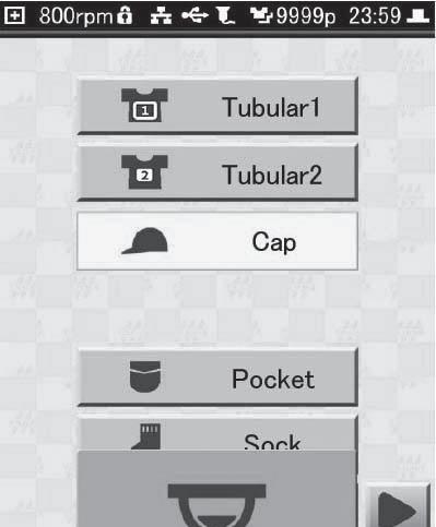
How to start the embroidery: "Chapter 3 How to Perform Embroidery"
Once the embroidery is complete, remove the cap.
1. Press the lock levers (three places), and remove the cap frame.
2. Remove the clips that were attached to the clip holders.
3. Open the latches and the lid frame.

In this chapter you will find information regarding needles and threads, which can help you create beautiful embroidery, instructions on how to perform routine maintenance for the machine, and measures to take when problems are encountered.
The following shows some representative examples of fabric, thread, and needle combinations to improve the quality of the finished embroidery. Please follow these recommendations.
Thin fabrics such as georgette and organdy
Felt, knitted fabrics such as T-shirts
Caps, thick fabrics such as denim
75d/2 or 120d/2
Polyester, rayon
No. 9 through 11
No. 9 through 12
120d/2No. 11 through 14
(*1) Indicated in denier format. The higher the number, the thicker the thread. The lower the number, the thinner the thread.
(*2) The lower the number, the finer the needle. The higher the number, the thicker the needle.
Fine needles such as No. 9 should be used for thin fabrics.
To prevent the breakage of the needle or the thread when embroidering thick fabrics, such as caps and denim products, use thick needles such as No. 12 or 14.
Switch to finer needles if the holes left after embroidery tend to stand out.
Regular maintenance is important to assure reliable, long-lasting use of the machine. In addition to periodically cleaning the machine, you should also apply oil at the specified locations.
The places shown below must be cleaned on a routine basis. Place extra care on keeping the area around the rotary hook and thread trimming knife clean, since waste thread, dust, etc. tend to accumulate there. If not kept clean, the quality of the embroidery may deteriorate. Make sure to adhere to the cleaning schedule.
Places to clean Frequency
Supplied accessories used Machine itself, operation panelRoutine—
Under the needle plateOnce a week
Z-shaped screwdriver Brush
Inside the rotary hookOnce a weekBrush
Inside the bobbin caseOnce a weekBrush
Tension baseOnce a weekBrush
Caution
Switch the power off before beginning the cleaning.
1. Use the Phillips end of the Z-shaped screwdriver to remove the screws from the needle plate, and then remove the needle plate from the bed.
2. Use the brush to clean away any dust or waste thread that may have accumulated around the thread trimming knife.
3. After cleaning is finished, attach the needle plate to the bed, and use the Phillips end of the Z-shaped screwdriver to fasten the screws.
Inside the rotary hook
1. Use the brush to clean away any dust or waste thread that may have accumulated inside the rotary hook.
Inside the bobbin case
1. Use the brush to clean away any dust or waste thread that may have accumulated inside the bobbin case.
Tension base
1. Use the brush to clean away any dust or waste thread from places where the upper thread passes.
The places shown below must be oiled on a routine basis.
All needle bars and felt inside the needle bar case
Once a week
Moving parts inside the armOnce a year
Caution
Switch the power off before beginning the task.
Flat head screwdriver (3 × 75) Oil
Phillips screwdriver (6 × 100) Oil
For lubrication, use either the supplied oil or commercially available sewing machine oil. Use of any other oil may lead to malfunction.
Do not apply too much oil. When there is too much oil, it can splatter and get the fabric or thread dirty and cause stains. If too much oil has been applied, use a cloth or the like to wipe it away.
Apply oil with the supplied nozzle attached to the tip of the oil bottle.
1. Apply a few drops of oil to the rotary hook raceway.
All needle bars and felt inside the needle bar case
1. From the gaps in between the take-up lever located in the upper part of needle bar case, apply a few drops of oil to the upper part of the needle bar. Apply oil to all needle bars.
2. Use a flat head screwdriver (3 × 75) to remove the screws at the right and left of the bottom cover, and remove the bottom cover.
3. Apply a few drops of oil to the felt inside the needle bar case.
4. Once the lubrication is completed, replace the bottom cover and fasten the screws at the right and left using a flat head screwdriver (3 × 75).
Caution
Be careful not to pinch any of the wires inside the needle bar case when installing the bottom cover.
1. Remove the caps from the screws at the two places on the cover on the right side.
The screw caps can be removed more easily if you insert tweezers or other narrow-tipped objects into the hole.
2. Use a Phillips screwdriver (6 × 100) to remove the screws in two places and remove the side cover.
3. Apply a few drops of oil at the locations shown in the illustration below.
•Vicinity of lubrication hole on shaft: (a)
•Moving part of lever: (b)
•Gold colored bushing: (c)
4. Once the lubrication is completed, replace the right side cover and fasten the screws in both places using a Phillips screwdriver (6 × 100).
5. Re-attach the caps over the screws.
The following explains the measures you should take when an error message is displayed, when you are unable to achieve the intended sewing results, or when other problems are encountered.
When the machine is operated incorrectly, or an abnormality occurs, the machine stops, and a message screen is displayed on the operation panel.
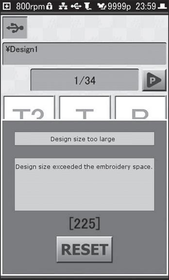
After checking the message and code that is displayed in the message screen, take the appropriate measures.
To dismiss the message screen, tap [RESET] in the message screen.
In some cases, depending on the type of error, the screen will not go away even if you tap [RESET] on the message screen. In such cases, turn off the machine's power, then turn it back on.
When a green message screen is displayed
This does not mean the machine stopped due to an abnormality or malfunction. Embroidery can be continued.
1B1Stop by frame stepping codeCarry out one of the measures below, and then continue with the machine's operation.
1B2Stop by Color Change
1B3Stop by end code
1B4Stop by thread trimming code
1B6Stop by automatic offset code
1B8Stop by temporary stop code
1C1Stop by stop switch
•Press the [START]/[STOP] button on the operation panel
•Advance/return frame operations
"4.9 Returning frame/advancing frame according to design"
These are displayed when settings for the machine are incorrect or it was not operated correctly. They can also be caused by a malfunction in the machine itself or by communication errors.
211Fixed position signal error
Fixed position signal cannot be detected.
221Frame Too Far Left
The embroidery frame moved to the limit position (left)(+X direction).
222Frame Too Far Right
The embroidery frame moved to the travel limit position (right)(-X direction).
223Frame Too Far Front
The embroidery frame moved to the limit position (front)(+Y direction).
224Frame Too Far Back
The embroidery frame moved to the travel limit position (rear)(-Y direction).
225Design size too large Design size exceeded the embroidery space.
281Color change error
Color change detection time, exceeded.
291Upper Thread Break
The machine detected thread breakage.
293Bobbin Thread Break
The machine has detected under thread breakage.
2B1Networking error Not connected with Network
2B3Data found in end code Data is found in end code.
2B4Function code error
Function code error
2B7Data set incomplete Data set is not completed.
2B8Pre-reading buffer error Output data is not ready.
Trim the thread manually, then return the main shaft to the fixed position.
"4.10.3 Trimming the thread manually"
If the issue cannot be resolved, contact your sales dealer.
Move the frame so as to make it possible to carry out embroidery within the limits of the frame.
"4.10.1 Moving the frame manually"
Tap [RESET] and check the position of the frame.
Stop use of the machine and contact your sales dealer.
Check the thread. If the thread is broken, replace the thread. Also, the tension base should be cleaned. If the issue cannot be resolved, contact your sales dealer.
"2.2 Threading the upper thread", "2.3 Setting the under thread", "8.2.1 Cleaning the machine"
Check to see if the bobbin has run out of thread, or if the under thread has broken. If the bobbin has run out of thread, or if there isn't much thread left, replace the bobbin with a new one. If the under thread is broken, replace it.
"2.3
Check to make sure that the LAN cable is connected properly, and that the settings on the PC or other devices are appropriate.
Modify the design using the dedicated design creation software or an optional DG product.
Select the design first, then start the embroidery.
Modify the design using the dedicated design creation software or an optional DG product.
2BAMemory capacity exceeded Memory capacity is insufficient. Contact your sales dealer.
2BBFrame back limit over Frame back reached the limit.
2BEIncorrect function code segment Functions with start/end are not registered in a pair of start and end.
2C7Password requested Input the password.
Do not return the frame any further.
Modify the design so that the start and end codes form a pair, using the dedicated design creation software or an optional DG product.
Contact your sales dealer.
2C9Time setting errorTap [RESET].
2CAPower OFF/ON incompleteTurn off the power, wait at least 5 seconds or more, then turn it back on.
2E3Power failure during operation Power supply failed during operation.
311Encoder A signal error
Encoder A signal does not vary.
312Encoder Z signal error
Encoder Z signal does not vary.
316Main shaft motor error
Main shaft motor or Motor driver is irregular.
321Frame driver irregular signal
Frame driver irregular signal, detected.
322X-Driver irregular signal
X-axis driver irregular signal, detected.
323Y-Driver irregular signal
Y-axis Driver irregular signal, detected.
32CX-axis frame travel incomplete X-axis frame travel is incomplete.
32DY-axis frame travel incomplete Y-axis frame travel is incomplete.
32EX-axis origin search incomplete X-axis origin search is incomplete in time.
32FY-axis origin search incomplete Y-axis origin search is incomplete in time.
354Motor overcurrent Sequin, Zigzag cord
362Jump motor overcurrent 382Color change error in 1 sec.
The needle position signal status during color change does not change for 1 second and more.
383Needle Position Error
There was no needle position signal during rotation of the main shaft.
3A6Movable Knife Open ATH Knife retractable position has become nonuniform.
Tap [RESET] to perform the power resume operation. "8.3.3 What to do if power is suddenly lost during embroidery"
Contact your sales dealer.
Tap [RESET].
If the issue cannot be resolved, contact your sales dealer.
Turn off the power, wait at least 5 seconds or more, then turn it back on.
If the issue cannot be resolved, contact your sales dealer.
Contact your sales dealer.
Carry out the procedure below.
•Turn off the power, wait at least 5 seconds or more, then turn it back on.
•Lower the rotation speed.
"3.3.6 Selecting the speed"
If the issue cannot be resolved, contact your sales dealer.
Contact your sales dealer.
3A9Upper thread hook motor overcurrentTurn off the power, wait at least 5 seconds or more, then turn it back on.
3C1Start/Stop switch error
The power was turned ON in the state that the stop switch has been accidentally pressed.
3D6CPU card error
Software installation error
3DBSystem RAM insufficient capacity CPU card
3DCMemory device error
CPU card (Memory device)
3DDSystem software installation error
CPU card (Memory device)
3DEExternal memory device error
USB memory
3DFMemory device broken
Time-based Functional limit
5B1Design information error
Data cannot be input. Information is not appropriate.
5B2Networking error (Software) Not connected with Network software.
5C1Frame origin memory incomplete Frame origin memory is incomplete.
6B5Communication Error Communication Error
6D1Frame parameter file error
Frame parameter file is irregular.
B01Formatting error Irregular formatting! Cannot read designs.
B04Empty media error
USB Memory is not inserted.
BC1Unregistered design No. Design No. is not found.
BF2Network setting error Network setting is incorrect.
If the issue cannot be resolved, contact your sales dealer.
Contact your sales dealer.
Turn off the power, wait at least 5 seconds or more, then turn it back on.
If the issue cannot be resolved, contact your sales dealer.
Contact your sales dealer.
Carry out the procedure below.
•Turn off the power, wait at least 5 seconds or more, then turn it back on.
•Replace with a different USB memory (USB flash drive).
If the issue cannot be resolved, contact your sales dealer.
Turn off the power, wait at least 5 seconds or more, then turn it back on.
If the issue cannot be resolved, contact your sales dealer.
Check the design.
Check to make sure that the LAN cable is connected properly, and that the settings on the PC or other devices are appropriate.
Carry out the procedure for memorizing the frame origin.
"6.2.2 Memorizing the frame origin"
Contact your sales dealer.
Use the design after copying it from the PC using a new USB memory (USB flash drive).
Connect the USB memory (USB flash drive) to the USB port on the machine.
"3.3.1 Loading the design to be embroidered"
Copy the design from the PC to the USB memory (USB flash drive).
Correct the network addresses.
"6.4 Performing network settings"
Often, the cause of problems can be things such as the needle condition or the thread tension. Refer to the following and try to determine the source of the problem. If the cause cannot be identified, or the problem persists even after the recommended measures have been taken, consult with your sales dealer.
Thread often breaks
Improper thread tension. Adjust the tension of the upper thread and under thread.
Upper thread doesn't flow properly.Replace the upper thread.
Direction of needle is bad. Needle is bent.
Adhesive from appliqué has stuck to needles.
•Rotary hook is dirty.
•The rotary hook has not been oiled.
•Adjust the position of the needle so that its groove faces forward or slightly to the right.
•Replace needles.
•Remove the adhesive from the needles.
•Replace needles.
•Clean the rotary hook.
•Lubricate the rotary hook.
Design data contains numerous tiny stitches 0.5 mm or less. Eliminate tiny stitches.
The embroidering position with respect to the fabric is too high or is too low.
Reposition the fabric on the embroidery frame so that it only lightly touches the needle plate.
Needle bars have not been oiled. Lubricate the needle bars (once per week).
Height of presser foot inappropriate. Adjust the height of the presser foot so it is matched with the height of the material. (*1)
"3.4.2 Checking the tension of the upper thread", "2.3.2 Putting the bobbin in place"
"2.2 Threading the upper thread"
"2.1 Replacing needles"
"2.1 Replacing needles"
"8.2.1 Cleaning the machine"
"6.3.2 Eliminating tiny stitches"
"2.4 Mounting the fabric on the embroidery frame"
"8.2.2 Lubrication"
(*1) For information on how to perform the adjustment, consult with your sales dealer. Needle breaks
Improper thread tension. Adjust the tension of the upper thread and under thread.
The density of satin stitches is extremely high. Modify the design. Eliminate unnecessary basting. (*1)
Fabric is too thick or too hard. Use fabric that is more suitable for embroidery.
"3.4.2 Checking the tension of the upper thread", "2.3.2 Putting the bobbin in place"
"8.1 Producing beautiful embroidery"
Cause Measure to take Reference
Bobbin is deformed.Replace the bobbin.
•Tip of needle is smashed.
•Needle not suitable for design or fabric being used.
•Replace with a new needle.
•Replace with appropriately sized needle.
"2.3.2 Putting the bobbin in place"
"2.1 Replacing needles"
Machine vibrates a lot. Level the machine using the adjusters. Setup Guide
(*1) For details, refer to the manual for the design creation software that is being used.
Sewing results not good
Cause Measure to take Reference
Improper thread tension. Adjust the tension of the upper thread and under thread.
Upper thread doesn't flow properly.Replace the upper thread.
Fabric or thread not suitable for design being used. Change the type of fabric or thread.
The way in which the embroidery frame was set up, or the way the fabric was put in place was inappropriate.
•Set up the embroidery frame correctly.
•Make sure that the fabric is securely held in the embroidery frame.
Needle size is inappropriate. Replace with new needles of the appropriate size.
"3.4.2 Checking the tension of the upper thread", "2.3.2 Putting the bobbin in place"
"2.2 Threading the upper thread"
"8.1 Producing beautiful embroidery"
"2.4 Mounting the fabric on the embroidery frame"
"2.1 Replacing needles"
If the machine's power is suddenly cut off due to a power outage, an error message screen [2E3] is displayed when the power is turned back on. If you want to continue the embroidery after clearing the error, make sure to perform the necessary restore procedure so that the embroidery position will not be misaligned.
Caution
Do not place hands or anything else near the frame. Otherwise, there is a risk of injury due to the movement of the frame.
1. Tap [RESET] in the error message screen to clear the error. The power resume confirmation screen is displayed.
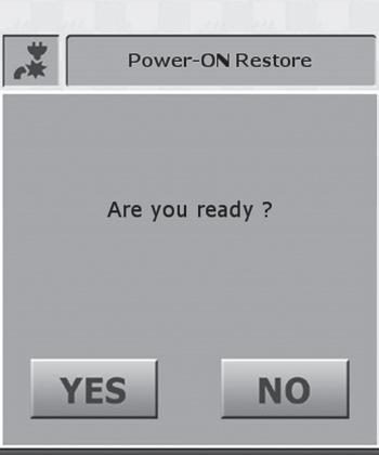
2. Tap . The thread trimming confirmation screen is displayed.
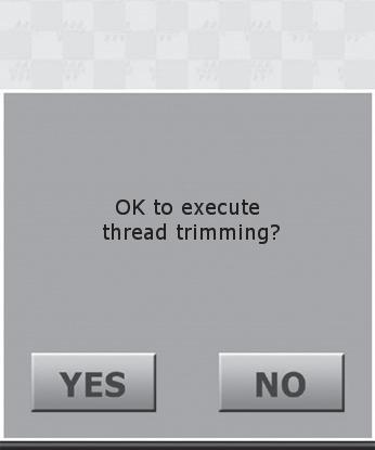
3. Tap . Tap when the thread is not connected to the fabric.
The machine will carry out a power resume, and the frame will move.
4. Check to make sure that the embroidery position in the design is not misaligned. Press the [START] button on the operation panel to continue the embroidery.
When repair stitching is needed, reverse the frame a little, and determine the position from which the embroidery should be resumed.
"4.9 Returning frame/advancing frame according to design".
Machine main unit
Item
ModelMDP-S0801C(200×300)S
Power supply24V DC
Rated current3.8 A
Rated electrical power 92 W
Weight37 kg
Attach an embroidery frame 28
B
Barcode reader 16, 51
Bed 15
Bobbin 23
Bobbin case 23, 102
Bring frame out 61
C
Cap fame 92
Cap frame unit 92
Change needle position 64
Cleaning 101
Cleanup 84
Conditions governing thread trimming 75
Confirm Frame Type 82
LAN cable 48, 51
LAN port 16
Laser crosshair marker 66, 75
Letter embroidery 68
Load a design 29
Lubrication 102
Machine information 89
Machine main unit 15, 16
Maintenance function 91
Manual 63
Memorize frame origin 76, 78
Move frame manually 63
Needle bar case 15
Needle number 20, 31, 53, 54
Needle replacement 19
Network settings 85
Date/time setting 87
Design creation software 48, 51, 67
Design orientation 32
Display Language 88
Eliminating tiny stitches 84
Error message 105
F
Favorite 44
Forced Trace 81
Frame limit 79
Frame movement 33
Frame setting 76
H
Hiding icon 43
Home screen 17
Operation panel 15
Pause 56
PC 48, 51
Power inlet 16
Power switch 16
Records 46
Return frame to the original position 80
Return frame/advance frame 62
Return stitches 74
Rotary hook 15, 24
Rotary tension disk 21
Sewing speed 35
Specifications 112
[START] button 15, 37
Start point 32
Step 31, 52
[STOP] button 15, 38
T
Thread breakage detection 73
Thread color 58
Thread course 15
Thread guide 21
Thread pressing shaft 21
Thread stand 15
Thread tension 15, 41
Thread trim length 74
Thread tube 15
Trace 34
Trim thread manually 65
U
Under thread setup 23
Upper thread setup 20
Upper thread tension 41
USB port 16
WWallpaper color 90
Manufactured by:
NO.1800, Ushiyama-cho, Kasugai, Aichi-pref., 486-0901, Japan
Telephone:568-33-1161
Fax:568-33-1191
Distributed by: Tajima Industries Ltd.
NO.1800, Ushiyama-cho, Kasugai, Aichi-pref., 486-0901, Japan
Telephone:568-37-1130
Fax:568-37-1230