FIRST
PG.
03

01 LIGHTHOUSE OASIS
Group Project: 3 People
1102 Pacific Coast Hwy, Huntington Beach, CA 92648
Professor Steve Fuchs
The project brief was for the creation of a motel facility to replace the former SunnySands Hotel in Huntington Beach. Our collective objective was to craft a space that resonates with familiarity while seamlessly integrating key architectural motifs from the surrounding locale.
Inspired by the rich architectural tapestry of Huntington Beach, our design ethos merges elements of Mediterranean architecture with contemporary sensibilities, reflective of the vibrant coastal community. This synthesis is particularly evident in the substantial columns reminiscent of Mediterranean structures, juxtaposed with the sleek lines characteristic of contemporary design.
The lobby serves as a focal point, embodying the essence of contemporary architecture through its expansive, light-filled expanse. Embracing natural illumination, the open-concept layout fosters an inviting atmosphere conducive to guest engagement and relaxation. Moreover, our design ethos pays homage to cultural progressions while harmonizing with the local context. The incorporation of a butterfly roof and strategically placed bump-out windows exemplifies our commitment to celebrating cultural advancements while remaining anchored in the vernacular architectural language of the area.
aconceptualization and integration of two attached 2-story structures to the North of the property, as well as the implementation of a rock climbing wall and a shade wall to the South. These elements were instrumental in preserving a generous allocation of parking spaces for larger vehicles while seamlessly accommodating supplementary rooms and facilitating convenient bike parking. Additionally, the inclusion of a shower facility further augmented the guest experience, particularly for those partaking in the diverse amenities available in the vicinity. Tseamlessly with the broader design vision.


The project mandate entailed the creation of an ADU for a client of choice, with a focus on drafting comprehensive architectural and structural plans, accompanied by meticulous documentation including details, schedules, floor plans, elevations, sections, and site plans.
Electing Piet Mondrian, renowned for his groundbreaking contributions to modern art, as the client, I embarked on a design journey aimed at crafting a permanent residence that not only nurtured his artistic endeavors but also served as a sanctuary from the geometric and austere compositions emblematic of his later works.
Drawing inspiration from Mondrian’s profound affinity for the cityscape of New York, epitomized in his seminal piece ‘New York City,’ the spatial layout adopts a grid system reminiscent of the urban fabric, instilling a sense of order and coherence reflective of his artistic ethos.
Understanding Mondrian’s penchant for structured living environments, juxtaposed with the inherent rigidity of his artistic oeuvre, the design narrative sought to reintroduce elements of natural harmony and warmth into the dwelling. Enveloping the 1st story glazing with lush vegetation, including Japanese False Cypress trees renowned for their abstract yet intricate nature, along with accents of white tulips and woodland purple sage, serves as a poignant tribute to Mondrian’s affinity for the natural elements. Beyond mere aesthetics, this verdant landscape infuses the home with vitality and dynamism, as the morning light filters through the foliage, casting intricate patterns of light and shadow across the interior spaces.
Beyond aesthetic appeal, the vegetation not only provides a connection to nature but also imbues the living environment with a sense of tranquility and rejuvenation. This integration of natural elements not only pays homage to Mondrian’s artistic ethos but also enriches the lived experience within the dwelling, fostering a harmonious coexistence between art, nature, and habitation.
In homage to Mondrian’s iconic use of primary colors, the interior gypsum board and exterior stucco finish are rendered in off-white tones, allowing the surrounding foliage to take center stage. The flooring, adorned in variations of light grey, complements the dark grey accents of the fixtures, creating a harmonious interplay of hues and textures.
FOUNDATION PLAN PLUMBING PLAN
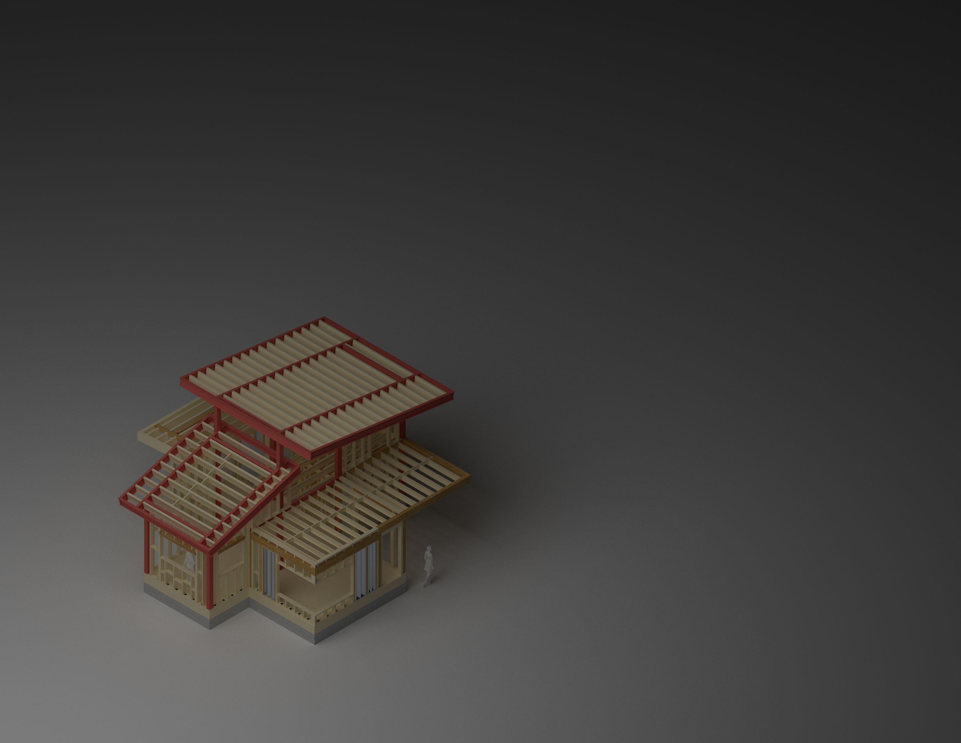
W12X14 FLYING STL RAFTER
4X12 R.R @ 12” O.C.
4X12 OTR @ 12” O.C.
2X6 BALLOON STUD @ 12” O.C.
STL MOMENT FRAME (SEE SHT S6)
STL MOMENT FRAME (SEE SHT S6)

LAPPED 2X9 TJI F.J. @ 12” O.C.
6X10 CROSS LAM TIMB BM
LAPPED 2X9 TJI D.J. @ 12” O.C.
6X12 PARALAM HDR
4’ SIMP. HRDY FRM
2’ SIMP. HRDY FRM
2X6 PT SILL PLT
ANCHR BLT @ 20” O.C.
2X12 RIM JST
RAISED FOOTING (SEE FDN PLN)
4X12 GIRDER BM
MOMENT FRM PST

The premise of the project is to create a mixed-use high rise with a parametric facade.
This configuration of Solaris is a parametric 34-story highrise. With 2 floors for commercial and 32 floors for residential, it utilizes a filleted hexagonal slab to allow for 360 deg of balcony space. Inspired by the iconic Al Bahar Towers in Abu Dhabi, Solaris’s facade emerges as a beacon of sophistication and sustainability. Encompassing 200 degrees of the high-rise, the facade serves as a formidable barrier against southern heat gain and UV exposure, ensuring optimal comfort and environmental consciousness. The dynamic facade system, reminiscent of nature’s elegant choreography, responds adeptly to the sun’s orientation and angle, seamlessly adjusting to minimize solar heat penetration. This technological marvel not only mitigates energy consumption but also affords Solaris the distinction of boasting a fully glazed exterior, affording residents unparalleled vistas of Los Angeles’s captivating skyline.

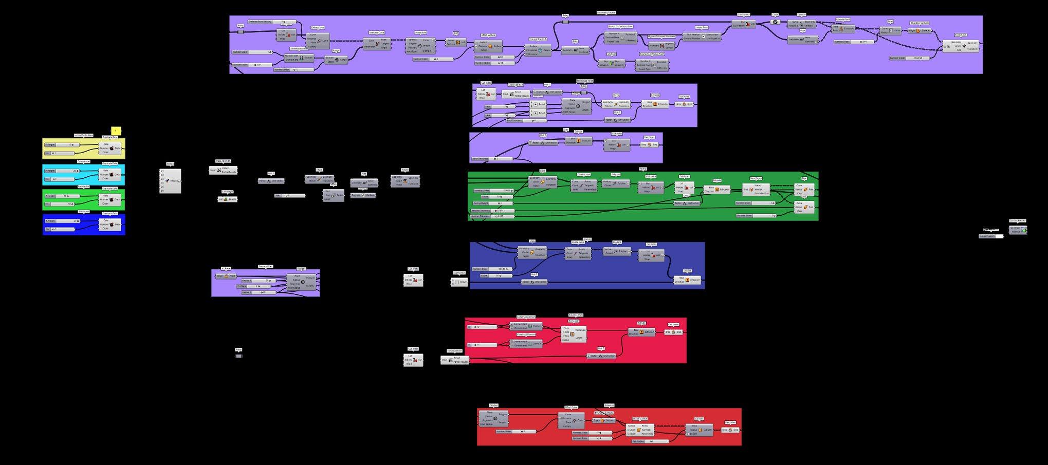
How This Scipt Works
This script begins by gathering input from the user regarding the desired number of stories for the lobby, commercial, residential, and penthouse sections of the project, as well as the height of each floor for these sections. This data is then combined and sent directly to four groups of components.
The first group enables users to design floor plates with flexible shapes, including polygons with various angles and curves. The second group focuses on the penthouse roof, which maintains a fixed shape regardless of the floors below.
The third group handles glazing, creating offset windows on each floor that can be adjusted in height and depth according to the floor height. The fourth group deals with the elevator shaft, which is a cube shape and requires only the total height of the project, including A penthouse roof.
The first group feeds into the railing group, which generates a rail system offset 2 feet from the edge of the floor plates, including rail glazing and mullion spacing. It also feeds into the floor plate group, which extrudes the polygons and lists them, along with the column group allowing users to add columns in any configuration needed.
Lastly, the first group contributes to the facade group, which creates a planar surface from the top to the bottom of the tower, within the bounds of the floor plates, ensuring a 5-foot gap for mounting. It then generates triangle panels sorted along the outer edge of each pedal, along with components for opening and closing the pedals. Additionally, it includes several components allowing users to adjust the orientation of the pedals in response to the sun’s position and the angle of direct light at specific times of the day.


04 LONGGANG OVERPASS PRECEDENT STUDY
Group Project: 4 people
Shenzhen China
Professor Joseph Sarafian
LEGEND
LONGGANG OVERPASS BRIDGE
SHOPPING AND RETAIL
HIGH DENSITY RESIDENTIAL
PLAZA/GARDEN
PUBLIC FACILITY
LONGGANG INFORMAITON HUB/TV STATION
SCHOOL
The premise of the project was to study various public infrastructure projects that benefited the public, my group was tasked with analyzing the Longgang Overpass in Shenzhen, China. We were to look at the project’s cultural, functional, and architectural significance.
The Core Area, also known as Central City, is situated within the Longgang District of Shenzhen, Guangdong Province, China. Renowned for its rapid economic growth and modernization, this area stands as a symbol of progress.
The research on the “Nine Dragons Overpass” and the adjacent corridor offers valuable insights for architects in designing and space planning in several ways.
Cultural Sensitivity: Understanding the cultural significance of the Nine Dragons Scroll and its representation in the overpass design underscores the importance of cultural sensitivity in architectural projects. Architects can draw inspiration from local heritage and traditions to create designs that resonate with the community and contribute to a sense of place. Symbolism and Meaning: The symbolism of the nine dragons as symbols of strength and good fortune illustrates the potential for architecture to convey meaning and symbolism. Architects can incorporate symbolic elements into their designs to evoke emotions, tell stories, and create memorable experiences for users. Contextual Integration: The location of the overpass and corridor within the urban fabric highlights the importance of contextual integration in architectural design. Understanding the surrounding environment, including neighboring buildings, infrastructure, and cultural landmarks, can inform design decisions and enhance the overall coherence and connectivity of the built environment. Multi-Functional Spaces: The corridor’s role as a vital artery linking diverse commercial, residential, and pedestrian areas demonstrates the potential for architecture to serve multiple functions and cater to the needs of different user groups. Architects can explore innovative approaches to space planning that maximize flexibility and adaptability, allowing spaces to accommodate a variety of activities and functions over time.
LEGEND
LONGGANG OVERPASS BRIDGE
SHOPPING AND RETAIL
HIGH DENSITY RESIDENTIAL
PLAZA/GARDEN
PUBLIC FACILITY
LONGGANG INFORMAITON HUB/TV STATION
SCHOOL
South East facing isometric site map.Exploded axonometric diagram of the components of the bridge.
SHADING
PLANTERS/SEATING
STAIRS
PEDESTRIAN OVERPASS
STEEL BEAMS
CONCRETE COLUMNS

Individual Project
6551 Park Blvd, Joshua Tree, CA 92252
Professor Don Lee
The project aims to establish a dynamic hub where the public can explore and engage with cutting-edge technologies in an immersive environment. The facility will feature 12 living units tailored to accommodate various needs, alongside 1600 square feet allocated for research laboratories, 600 square feet designated for office space, and an additional 600 square feet for conference facilities. Complementing these areas, an 800-square-foot cafeteria and kitchen space will cater to visitors’ dining needs, while a spacious 2000-square-foot community center will serve as a vibrant focal point for gatherings and activities. Alternatively, a lobby with gift shops will provide a welcoming entry point for visitors.
Geosynthesis embodies a fusion of state-of-the-art green technology with the natural splendor of its surroundings, symbolizing the geological processes that have shaped its iconic rock formations. This synthesis creates a harmonious environment that not only educates but also inspires visitors to embrace innovation while fostering a deeper connection with the world around them.
VICINITY MAP
EXPLODED AXON OF THE PANELING SYSTEM
Community Center
LEGEND
Office Lab Residential BIO
PCM
Phase change materials use a physical effect to store large amounts of heat or cold with nearly no loss and release later.
When heated and reach melting temperature, the temperature stays nearly constant until melting process is completed.
TINTED FILM BIP
Shields interior spaces from the public eye.
Reflects heat, and protects against ultraviolet rays.
Reduces glare offering a more comfortable viewing experience. inside.
DEG
One drop of water released from a height of 6 inches can generate a voltage of over 140V, essentiall powerin 100 small LED lights
As the water droplets hit the surface and spread out, the drops act as a ‘bridge’ that connects 2 electrodes.
Improves air quality, reduces heat island effect
Can be utilized for growing local produce Minimizes heat loss and cooling loads, reduces rainwater runoff.
SOLAR
The Sequin panels indiviually tilt allowing for freedom to orient for efficiency.
PV cells in the panel absorb sunlight, creating electrical charges that move in response to an internal electrical field in the cell.
EXPLODED PROGRAM DIAGRAM AXON
AVERAGE TEMPERATURE
SW-NE: 3-10 mph
8 MOS Oct - May
COMMUNITY CENTER AND CAFETERIA
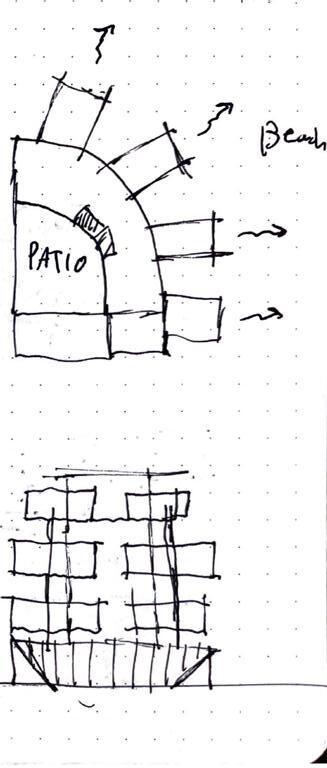
Situated in the Northern corner due to adjacencyt to Joshua Tree Visitor Center. The building is designed to reduce southern exposure. This strategic placement provides a suitable patio for gatherings while also shielding guests from western winds.
LABS AND OFFICES
Located near the community center and west of the site for easy access and lab tours, guides guests to the lab area, ensuring privacy for living units. The orientation also maximizes northern glazing. Additionally, the orientation channels western winds through the site, naturally cooling the air as it passes through the green space.
LIVING UNITS
Centrally located to the East in a secluded area from the lab and community center, the structure emphasizes privacy and a central presence within green spaces, creating a welcoming environment. The open orientation promotes shared spaces, with 2nd-floor patios facilitating interactions between lab and visiting residents. Furthermore, the structure is designed to channel western winds, providing natural cooling as the wind passes through the green area.
GREEN SPACE
Placed at the site's center, the main park offers guests constant access, providing a preview of the surrounding area and showcasing water-efficient vegetation. Additionally, the central green space cools and filters western winds entering the site, while the rear green area ensures privacy for the East-side living units.
CONCEPT DIAGRAM


06 KEYSTONE GALLERY

The project brief called for the creation of a gallery space spanning the Santa Ana River near Victoria St., with the potential to interface with the existing four-lane bridge connecting Costa Mesa and Huntington Beach.
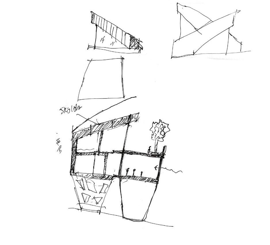
Inspired by personal experiences biking past the site en route to fishing excursions with friends, I recognized the urgent need for a pedestrian bridge to offer a safer alternative to the hostile four-lane bridge. The envisioned space aims to provide a serene atmosphere where beachgoers can pause, appreciate the scenic beauty, and immerse themselves in the fusion of art and nature.
In alignment with the programmatic objectives, the main entrance to the gallery faces East, catering to the majority of pedestrian traffic from upstream. Positioned adjacent to the entrance, the lobby offers guests the option to indulge in refreshments before exploring the gallery or venture directly inside. The cafe, designed to capitalize on abundant northern light, seamlessly integrates with the surrounding landscape. Conscious of seasonal variations, all glazing faces North to mitigate heat gain during the Summer and Spring influx of guests. Conversely, the gallery spaces prioritize controlled lighting conditions to showcase artworks without compromising comfort.

The second floor serves dual functions as a viewing deck and a platform for outdoor sculptures, complemented by seating areas above the pedestrian bridge. Supported by trapezoidal posts and beam systems, these platforms facilitate a covered pedestrian lookout point, enhancing the overall user experience.
Guided by these program elements, the project’s physical form embodies the trapezoidal motif, extending from the embedded concrete support system to the floor plates. This cohesive design language reflects a seamless integration of function and aesthetics, promising a dynamic and inviting space for visitors and art enthusiasts alike.


Trapezoidal Shape Mullion
Gallery Platform/Seating
Semi Transparent Glass
Wood Treated Timber Trellis
Covered Bike Lockers
Pedestrian Bridge
View Plaform/public rest area
Wood Treated Timber Trellis
Concrete Columns


SUPPLEMENTARY WORKS
Photography, for me, serves as a transformative medium through which I explore the world from perspectives I might not otherwise encounter. It’s the art of freezing moments in time, compelling me to stay present, alert, and attuned to life’s fleeting beauty. This practice of being fully engaged in the present moment. In many ways, photography becomes a catalyst for mindfulness, encouraging me to immerse myself in the richness of each passing moment. This heightened awareness extends beyond the act of taking photos; it informs how I perceive and interact with the built environment around me. As I frame a shot, I become acutely conscious of the lines, textures, and atmospheres that define architectural spaces. It’s a symbiotic relationship: my experiences behind the lens inform how I envision and design the built environment, while my understanding of design principles enhances my photographic compositions.


Group Project: 3 People
Professor Joseph SarafianThis project embodies a deep exploration into the artistry and functionality of woodworking, serving as a platform to comprehend the foundational principles of the built environment. Inspired by the elegance and simplicity of furniture design, our collective endeavor aimed to distill these qualities into a small yet profound wooden table, crafted solely through the art of wood joinery.
Guided by the vision of my colleague, we embarked on a journey to imbue our creation with both form and function, harmonizing our contributions to achieve a unified design ethos. Adopting a minimalist yet refined approach, we embraced three key joinery techniques — the mortise and tenon joint, the groove joint, and the cross-lap joint — renowned for their stability and durability.
In the fabrication process, precision and craftsmanship were paramount. Utilizing the board saw, I meticulously cut the plywood boards to size, while my colleague utilized the CNC machine to mill the tabletop and top shelf, employing dog bone ends to ensure seamless perpendicular corners. I then used the bandsaw to carve out the legs with exactitude, employing laser scoring before cutting for precise alignment.
We then tirelessly sanded the plywood components to ensure a smooth and seamless assembly of the components, culminating in the application of a rich oak stain to the legs, juxtaposed against the natural warmth of the plywood. Through this process, we gained valuable insights, discovering the nuanced intricacies of wood staining and its impact on dimensional stability.
As our creation took shape, we encountered challenges and triumphs alike, refining our techniques and deepening our appreciation for the artistry of woodworking.


SHELF/BRACE
SHELF/BRACE
CROSS LAP JOINT
EXTENDED TENDON JOINT
EXTENDED TENDON JOINT
LEG
EXTENDED TENDON JOINT GROVE JOINT
LEG LAPED JOINT
LAPED JOINT
TABLE TOP (MORTISE JOINT)Individual Project
Doctor Dean Abernathy
The project brief presents an exciting opportunity to repurpose the site adjacent to the Long Beach Sports Arena for the upcoming Olympics, with a visionary plan to transition it into permanent housing for Downtown Long Beach residents post-games.
Our class has embarked on an extensive exploration, dedicating significant time to researching case studies and precedents to inform our approach. Currently, our focus lies on developing massing and forms that will shape the essence of the project.
Central to my design philosophy are core principles aimed at fostering a vibrant and inclusive community. I envision creating an environment conducive to multi-generational living, where families of diverse backgrounds can thrive. Incorporating spaces for young children to play and socialize will be integral to nurturing a sense of belonging and community cohesion.
Equitable access to clean air, natural light, and recreational amenities will form the bedrock of our design ethos. By prioritizing green spaces and recreational areas, we aim to promote physical and mental well-being while fostering a strong sense of connection to the surrounding environment.


FREELANCE ARCHITECTURAL DESIGNING
CLIENT OBTAINED THROUGH WORD OF MOUTH
The homeowner’s commission for a Jr. ADU reflects a thoughtful consideration of both present and future living arrangements, driven by the need for practical solutions and adaptability. With the intention of accommodating a family friend who assists with childcare, the decision to convert existing spaces rather than build anew demonstrates a keen awareness of spatial dynamics and the importance of preserving natural light and airflow throughout the property.
By repurposing the existing garage and room for the Jr. ADU, the homeowner ensures minimal disruption to the flow of Southern winds while laying the groundwork for a future full-sized ADU at the back of the property. This strategic approach not only maximizes available space but also fosters a seamless integration of living quarters, promoting functionality and flexibility in the home’s layout.
The conversion of a closet into a bathroom for the homeowner’s children further enhances the overall functionality and comfort of the living space, offering added privacy and convenience for the family. Moreover, the proactive decision to upgrade the water meter anticipates potential regulatory requirements and mitigates future costs associated with city plan checks and permitting fees, underscoring a commitment to long-term planning and efficiency.
(E)
PROPOSED FLOOR PLAN
WALL LEGEND WINDOWS/DOOR REFERENCES
1-HR WALL NOTE:
PONY WALL NOTE:
3040 SW SH SD GD BD PD FOOT HORIZONTAL INCHES HORIZONTAL FOOT VERTICAL INCHES VERTICAL
(E)EXISTING
