13 minute read
Manufacturing
#Protoype 1
TIMBER//STONE
Advertisement
1. TYPE OF INTERFACE
Rough pass
Finish pass
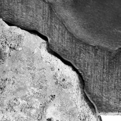
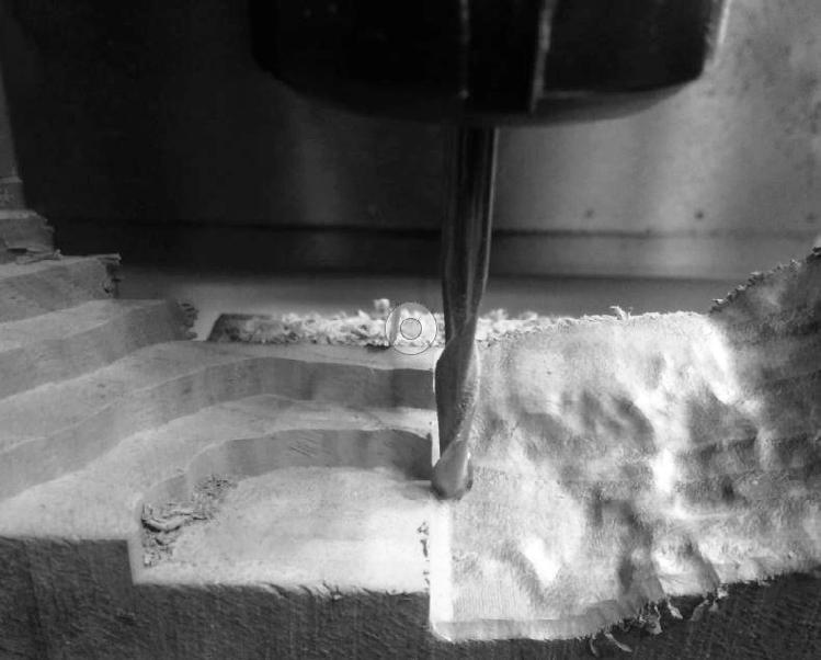
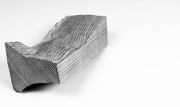
1. Type of Interface. Wood being an inherently stronger material was a good option for joint component. The resolution of the surface of the stone was captured on the wood to a high precision, through CNC milling.
2. MANUFACTURE PROCESS

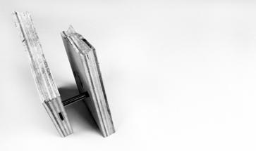
Single and double side milled wood that forms a solid joint component on the stone.
Double side milled wood in the form of a waffled structure. This allows for reduced amount of wood.
Irregular piece of waste wood that was used as stock material for single side milling.
Fusion toolpath (3D pocket machining path) for first pass of rough cut milling with 6 mm end mill.
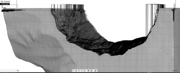
Fusion toolpath (parallel machining path) for finishing pass milling with 6 mm or 3 mm end mill.
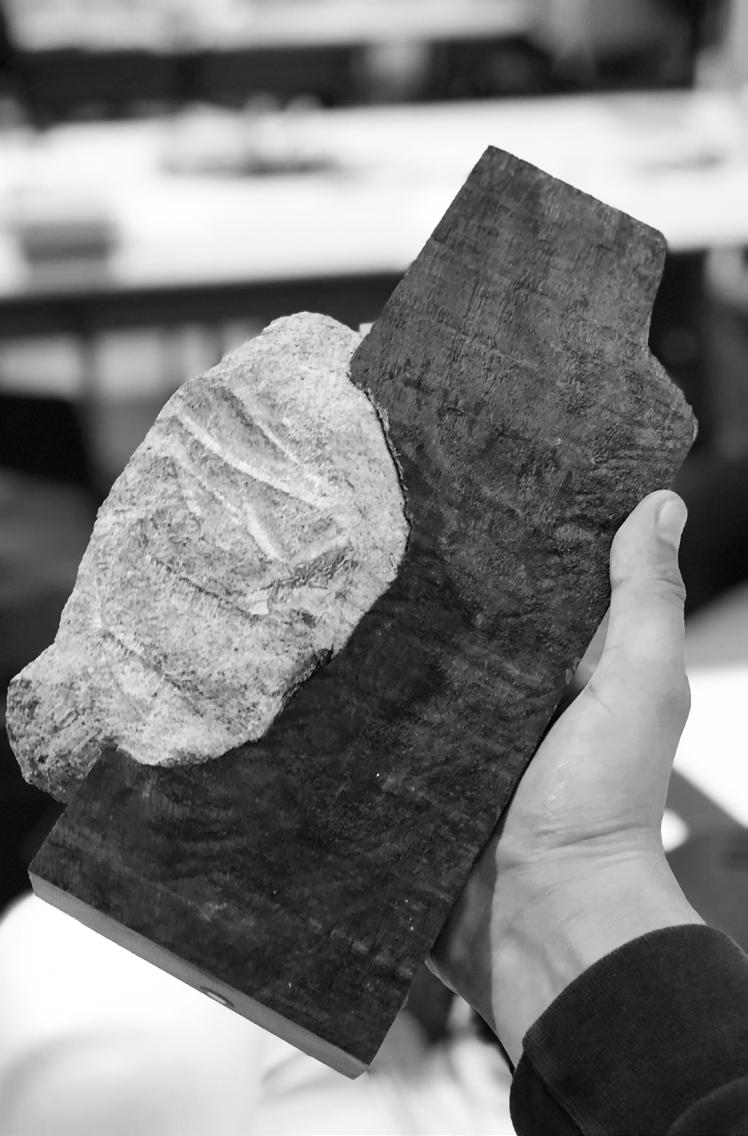
3. RESULTS 2. Manufacture Single side milling: The 3 axis CNC milling only required two tool changes, a 12 mm end mill for the rough cut and a 6 mm ball nose for the final cut based on the joint.
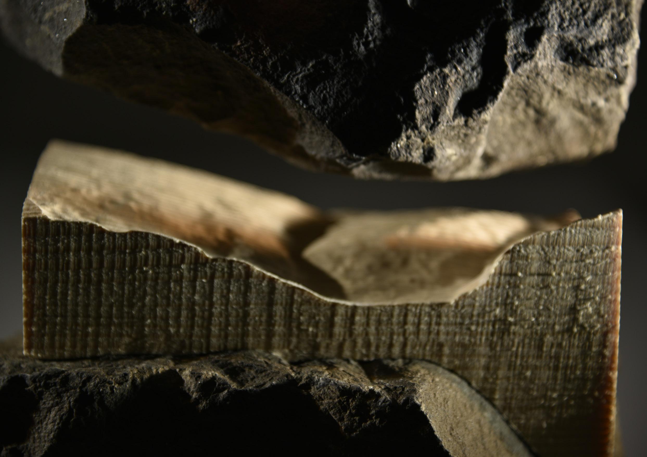
3. Results It provided high geometric tolerances while dealing with tight angles and provided good surface finishes. The major drawback for CNC milling with wood was working with undercuts. As the best gripping surfaces had undercuts, this could not be achieved on a 3 axis HAAS machine.
#Protoype 2
2. MANUFACTURE PROCESS
Manufacture This double sided milling required two setups on the fusion toolpath file. This was done using a 12 mm end mill cutter for the initial roughing pass. The finishing pass was done using a 6 mm ballnose cutter.
Aspects of quality: 1. Mesh resolution 2. Tool sizes, tool path 3. Wood texture and grain quality. 4. Undercuts in the geometry. Quality
Profile of the double side milled wood component.
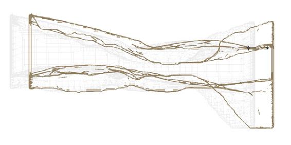
Fusion toolpath indicating the finishing toolpath (parallel machining path).

Surface mapping resolutions - results depend on the process of manufacture. Significant variations between subtractive (CNC, robotic milling) and additive manufacture (fds printing) indicate different capabilities and limitations.

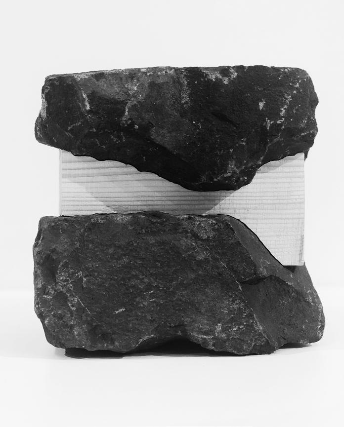
3. RESULTS
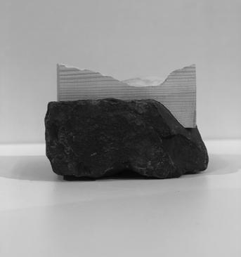
Limitations - CNC The major drawback for CNC milling with wood was working with undercuts. As the best gripping surfaces had undercuts, this could not be achieved on a 3 axis HAAS machine. High resolution that fit very well with the surface of the stone.
#Protoype 3
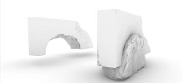
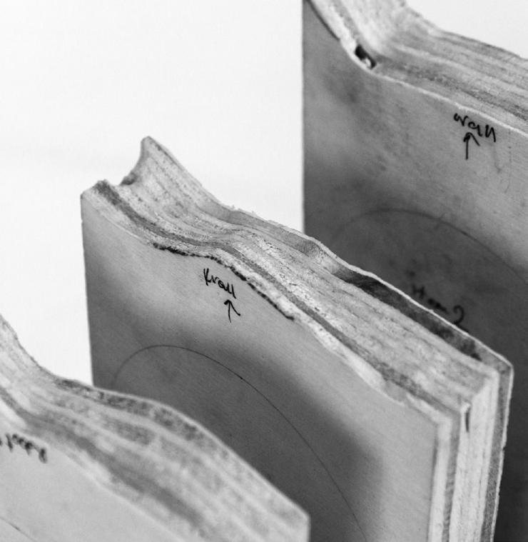
Waffled approach to creating smaller wood elements that can include undercuts. The undercuts, to an extent, could be addressed by Kuka KR60. Intent
2. MANUFACTURE PROCESS

This prototype required a special robotic cell setup, with a jig that allowed for the wood piece to be held.
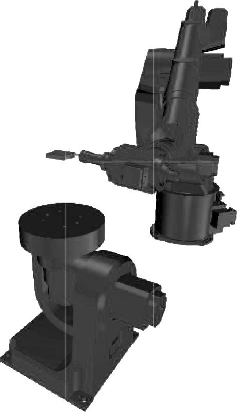
Three holes were made on all the small wood elements. These were precisely lined up on the jig for every milling operation, maintaining precise alignment. Manufacture

3. RESULTS
JIG development.
The jig was specially made for this robotic milling operation. Requirements for the jig: - Sufficient height from rotary table to avoid collision between robot and rotary table. - Central rod for securing the wooden piece. - Two additional rods to avoid any turning/rotation in the wood while milling. - Held such that the robot can mill from all directions. Link: https://vimeo.com/374643617m/374653006com/374653006
Toolpath of the robot. It extends outside the piece to ensure a clean finish on the wood.
Machining review. It captures better undercuts in comparison with 3 axis CNC milling . However, this compromised on the accuracy of the milled surface. Other significant drawbacks were the size of the stock material required in order to accommodate appropriate work holding, this contributed to wastage of wood.
#Protoype 1 & 2
METAL//STONE
1. TYPE OF INTERFACE
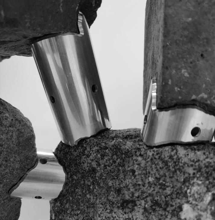
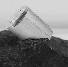
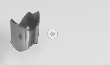
1. Type of Interfaces. Aluminum is easy to machine and highly recyclable. Being durable and strong, it reduced the possibilities of chipping or tears with the stone, unlike wood. The prototypes were significantly different from each other because of the type and performance of their interface.
2. MANUFACTURE PROCESS
3 axis milling
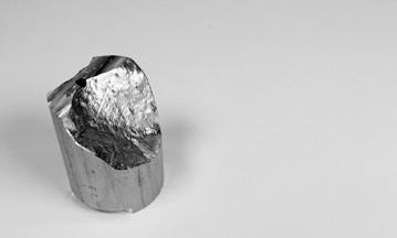
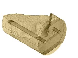
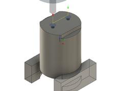
Solid 50mm aluminium rod milled on one side with a 3 axis cnc machine.
Hollow 35mm diameter aluminium pipe milled on both sides with a 4 axis cnc machine.
Most of the hollow components were done in under 90 secs at 90% of the feed rate. This method proved to be very quick and used minimal material.
Limitations - #1 A full-scale architectural system would easily require a large number of joint components, this process was not a viable one in terms of material usage and manual labor. The underperformance was also because of the bulk of the rod, which was a lot of material that did not actively engage with the stone in frictional locking.
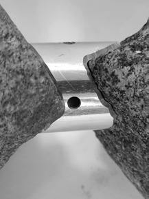
3. Results - #1 For the solid AL rod, the resolution was detailed and followed the surface profile of the stone. However, without the undercuts the gripping was not tight and caused slippage. The machining took 55 mins per component.
4 axis milling
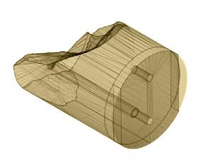
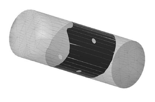
Fusion model indicating both sides of a split joint component that show the alignment holes that is used to align and fix them.
Fusion model of the piece held in place on a custom work holding that didnt need any flipping or realignment.
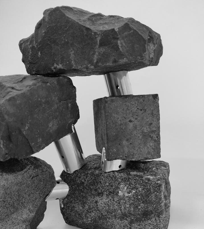
3. Results - #2 Once the work holder was set up, this method from the CAM diagrams to the execution was very time efficient. It fit better on the stones and overall performed better than the solid model.
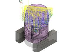
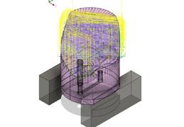
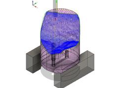
Machining paths: Scallop, Parallel, Ramping Tool sizes: 6 mm end mill cutter, 3 mm ballnose cutter Machining time: 55 mins per piece
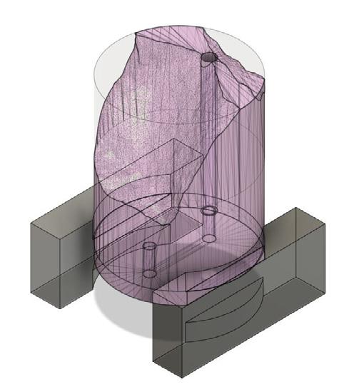
Toolpaths for first side/first setup


Toolpaths for second side/second setup
3-axis CNC machining [ subractive manufacture - metal//stone ]
Solid Aluminium rod - 50 mm Dia.
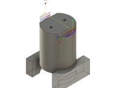

Custom workholder setup
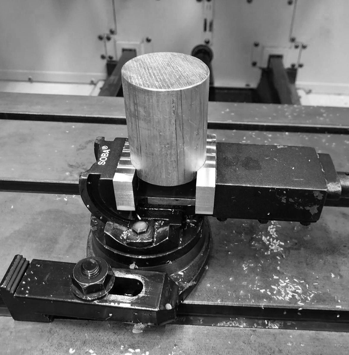
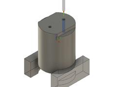
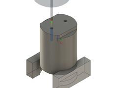
Manufacture - #1 A milling arrangement with two alignment holes was setup. Since the joint was split into two halves and put together with the alignment holes. Both parts needed to be milled. Work holding was crucial here. Even the slightest variation of alignment caused assembly failure.
5 mm dia. hole for piece align ment.
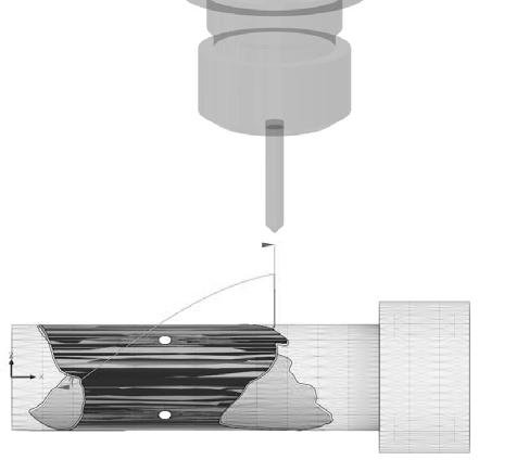
Machining paths: 3-axis rotational milling Tool sizes: 6 mm 45 degree V - cutter Machining time: < 90 seconds per piece
Fusion toolpaths for mapping the profile:
machining
Stone curvature profile mapped as an outline.
piece held in place with four M4 bolts.
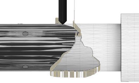
Same setups for various pieces:
Manufacture - #2 Wall thickness of tube - 1.85 mm. The machining strategy was altered so as to mill exactly what was required to cause an interlock, which was the undercuts. The zig-zag pattern was mapped along the perimeter of the tube using a 4 axis HAAS cnc machine. Done with a 6 mm 45-degree cutter and a work holder that allowed for both sides of the tube to be milled without any flipping or realignment to match the profiles.
Aluminium Jig to hold the pieces in place.
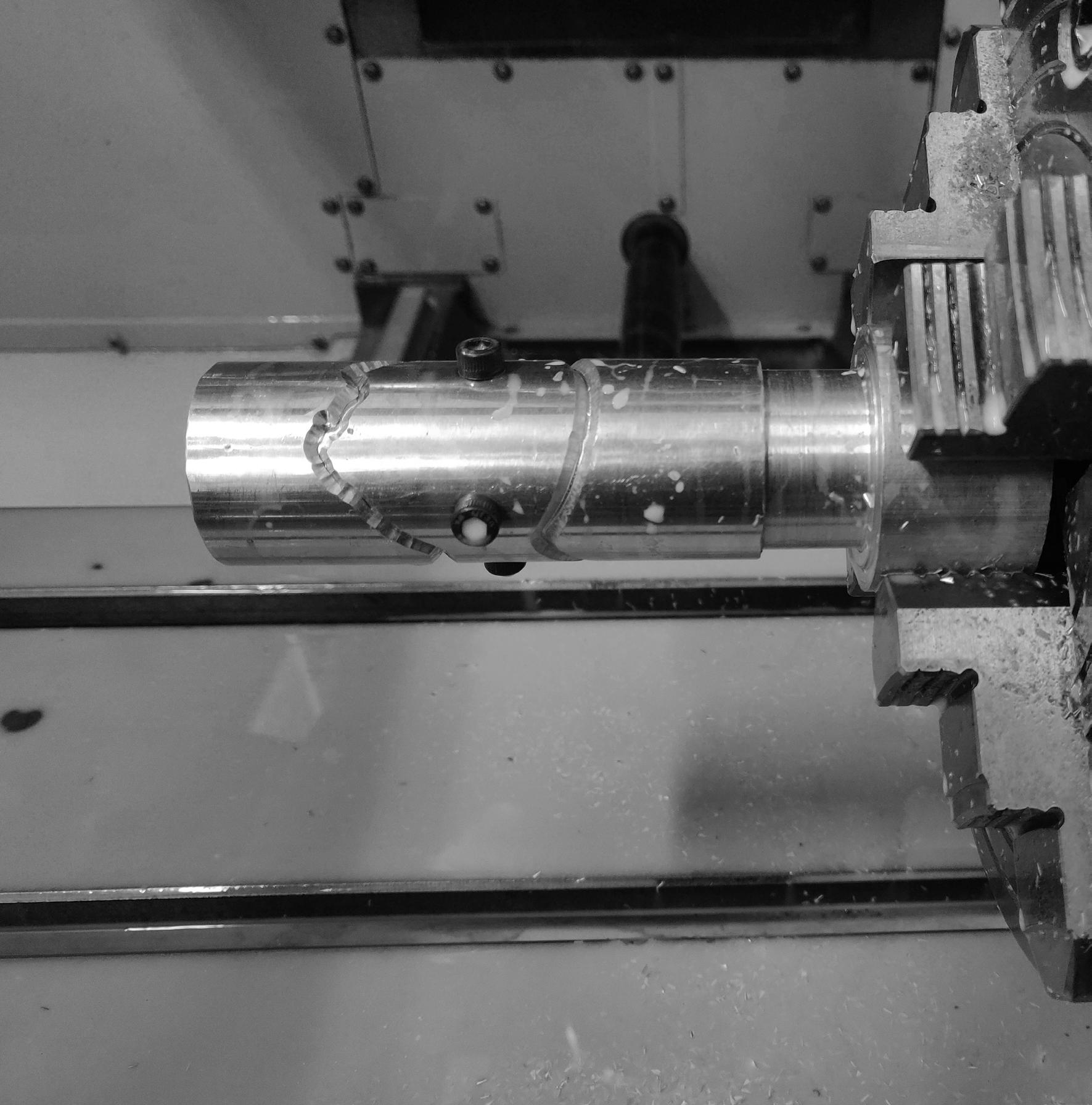
35 mm dia. Aluminium tube of 1.8 mm thickness.
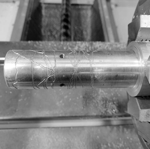
#Protoype 1,2 & 3
PLA//STONE

1. TYPE OF INTERFACE
1. Type of Interface. Fusion filament fabrication method is a material melting additive manufacturing method that is widely used for thermoplastics. By this method, the parts are made by a movable nozzle which deposits repeated layers that adhere to previous layers and bonds upon solidification.
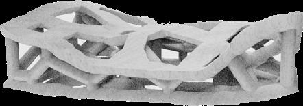
2. MANUFACTURE PROCESS 3D printed Voronoi joint component for reduced material.
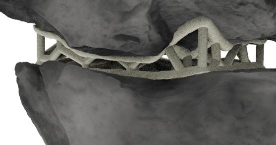

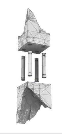
This 3D printed + steel rods joint component was designed for a specific criteria of adding height and using minimal 3D printing.
Link: https://vimeo.com/374644785m/374653006com/374653006
Fitting accuracy and strength
3. Manufacture All samples were printed with the Ultimaker Cura with an extruder diameter of 0.4mm and PLA filaments of 2.85mm diameter. They were printed with a raster gap (or layer thickness) of 0.2mm, at a printing speed of 100 m/s.

The mechanical interlocking of the joints showed unprecedented behavior. The parts have high contour resolution and fit precisely on the surface of the stone.
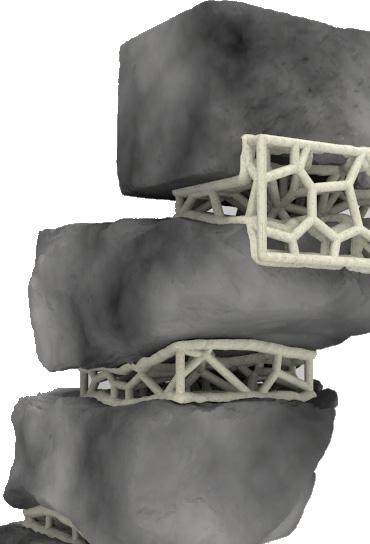
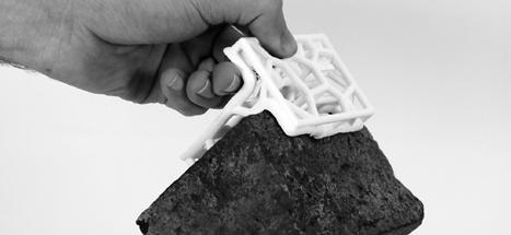
PLA allowed a certain amount of flex or ‘give’ which allowed forcing it into undercuts that then formed secure joints.

Depending on the requirement of the final design intent and the number of stones available. The joint components can be customized.
Intent Another experiment was a node-based approach that allowed for very specific small liaisons on the surface of the stone. This was based on a system of having the forces meet at the central node through square rods, providing a different aesthetic language
Limitations Infill density has to be very high increasing printing time. And despite a voronoi set up to reduce material, since it was FFF printing, material was lost on support structures.
3. Results The voronoi configuration was set up to reduce the material build up and test its strength against a similar solid fill part. It proved to be equally strong. The main variables that affect its performance are build orientation, layer thickness, air gap, raster angle, material type and manufacturing speed
#Protoype 3

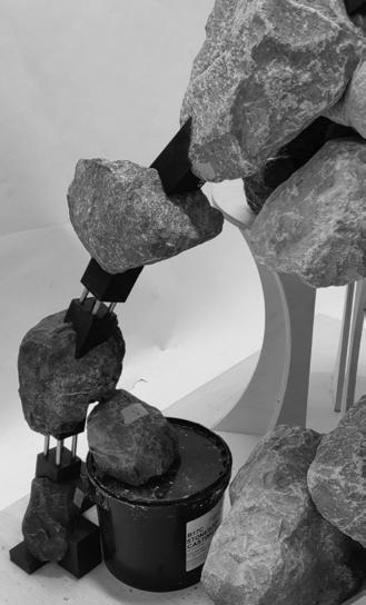
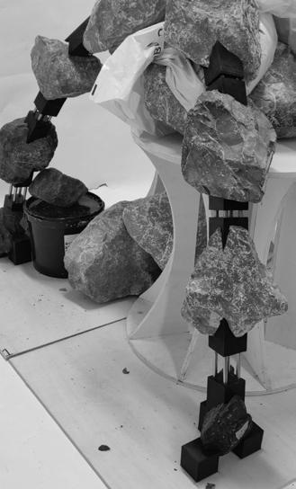
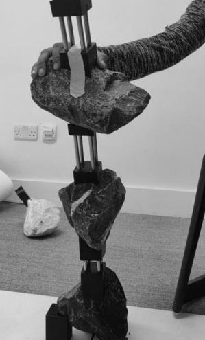
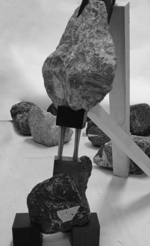
The in-between spaces can serve multiple applications that include, design intentions such as spanning larger distances with smaller number of stones. Possibilities
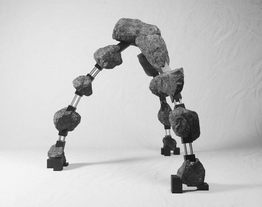
Pictures of work in progress of three legged arch model structure.
Intent and parameter based design experiment. Optimised with a specific target behaviour of the final overal structure.
13 stones
29 connections
From the different valuable qualities of the tests, a final model was developed that used metal rods to reduce the use of 3D printed material as well as to internalize within the overall design, parameters like increasing distance between stones etc. The rods helped achieve target height. 3. Manufacture
430 mm
670 mm 50 mm
variable length
1. Lack in appropriate scaffolding lead to difficulties in being able to build 2. The metal rods with the circular profile caused smalled rotational effect on the joints, which caused deviations as we built up. 3. Cumillative errors as we built up lead to misalignment of pieces. Failure
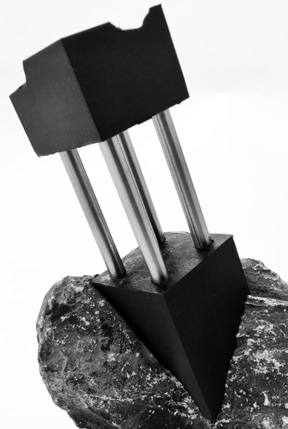
Max deviation with a slight undercut can help achieve a strong fit that can stay tight on the surface of the stone. 3. Results
While strong connections with high densities are printed they take long printing hours and are sometimes not uniform. For the purpose of spanning square profile rods would work better as it would avoid a rotational effect. 4. Outlook
Manufacturing Alternatives from System’s Engineering Point of View
• No computation • 100% of undercuts • 0 person • 24hrs per day, 168hrs per week
• A few hours of computation • ~0% of undercuts • 1 person • Only during workshop hours (6.5hrs per day, 32.5hrs per week)
• 2 day of computation • ~50% of undercuts • 1 or 2 person • Only during workshop hours (6.5hrs per day, 32.5hrs per week)
Alternatives Availability of Resources 3D Printed Voronoi All are available at BMade shop. However, it should be noted that the amount of the cost behind aluminum is more than PLA and that is more than timber/plywoo d 3D Printed single-sided with Aluminum rods 3D Printed Node Based With square rods
Solid Aluminum Cylinders –CNC Milling
Aluminum Pipes –CNC Milling
18mm Plywood Slates –Robotic Milling Cost Time Labour Precision Cons Pros
£25.00 per box (enough for about 20 to 30 mediumsized connections) £1 per connection. The ones with aluminum costs around £2 per connection £60 per meter, £4 per connection 10mins 0 90% Support material Strength
20 mins 2 90% 2 types of material
30mins 2 70% Cost Not optimized Slippery 2 types of material
5mins 1 80% Cost Weight Not optimized
£14 per meter, £1.4 per connection £8 per sheet (60*60cm) £1.33 per connection 5mins 1 70% Slippery from the surface
60mins 1 50% Limited in Depth Not stable Strength Multiple Parts Light and stable Aesthetics Porosity Optimised Excellent undercut gripping
Material Strength
Fast to produce Minimal material
Minimal material Aesthetics Porosity
Timber Chunk –Robotic Milling £7 per meter £1.4 per connection 60mins 1 90% Not optimized Depends on available stock Structural stability Strength Aesthetics Visual Opacity More control on the depth
33
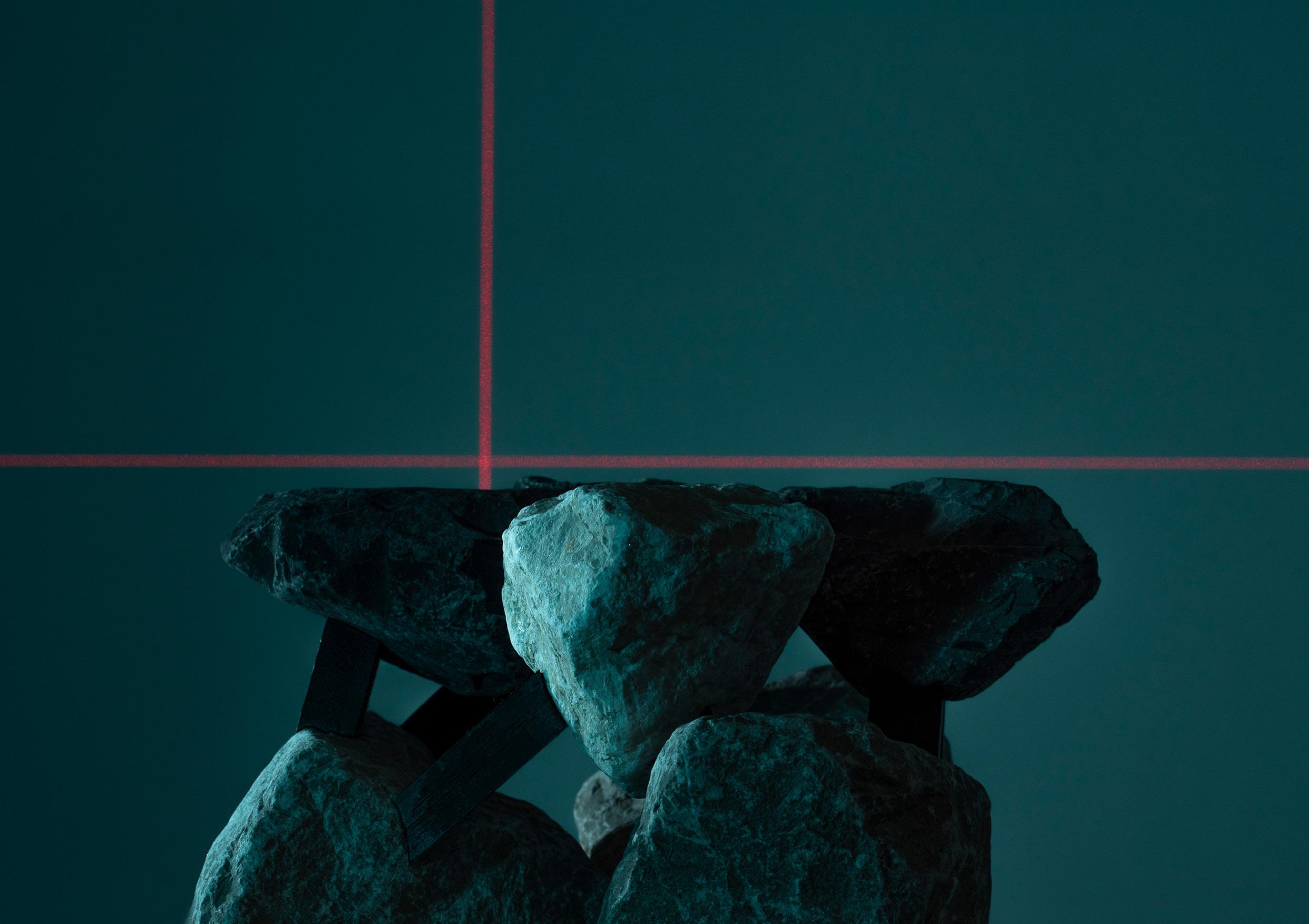
Design Intent was to establish a level datum. The flat surfaces were procedurally identified.
