
7 minute read
Augmented Reality
CONCEPT OF NOTATION - 3D DIGITAL GUIDANCE SYSTEM
Augmented reality Within this project, it was quickly evident that assembly by reference to a 2D diagram was a tedious process. It multiplied the complexities as the structures got larger with more connections. A 3 dimensional guidance system was required for easy assembly. function 1: MATERIAL SORTING
Advertisement

function 2: CONNECTION PLACEMENTS

function 3: SEQUENTIAL ASSEMBLY
function 4: VISUALIZATION
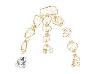
New form of notation A change from the traditional way of notation. A paradigm shift to a 3 - Dimensional notation to intuitively understand materials with its characteristics. A 3D digital guidance in design and construction through Augmented Reality, which enables digital layers that can aid and simplify the process of assembly.
#how can the irregularity aid augmentation?
Picking the right stone.
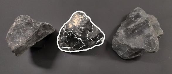
What? Recognizing the correct stone from a collection and highlighting it. Thereby, aiding in the sequential assembly of the structure.
How? The system distinguishes between the stones purely by their visual appearance. This implies that every guiding view must be different and their recognition range and angle is recorded.
Augmentation is developed for recognition and tracking of every element. Each stone acts as a unique model target that can be recognised by shape and features by the pre-existing 3D scanned data.
Rock specific data - the information is embedded in the material.
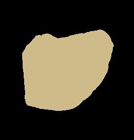
unique silhouette for each stone.
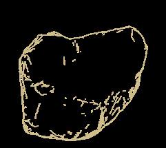
unique collection of ridges and valleys on each stone.
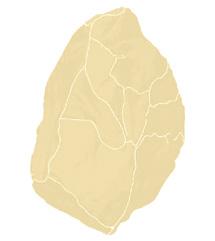
unique collection of viewing recognition range, angle and orientation.
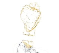
unique position within a structure.
Irregularity - An Advantage Same rock viewed in different orientations. All the different orientations provide a different rock profile and show different features on that face. This gives ample data for the augmentation to use.
Irregularity - An Edge
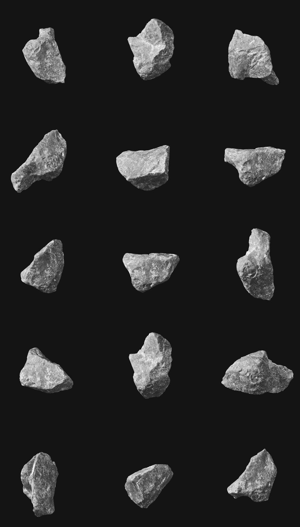
This sort of recognition would not be possible with a standardised building material such as bricks. This can aid very customised assemblies that serve very specific performance criteria.
#how augmentation works here?
#Function 1
3D scanned model
Designed with Rhino + Grasshopper
UNITY + VUFORIA (Software used for augmentation)
How? The most suitable method for AR in this project is the marker based approach. Unity enables apps built using Vuforia Engine to recognize and track particular objects in the real world based on the shape and features of the object.
Key features:
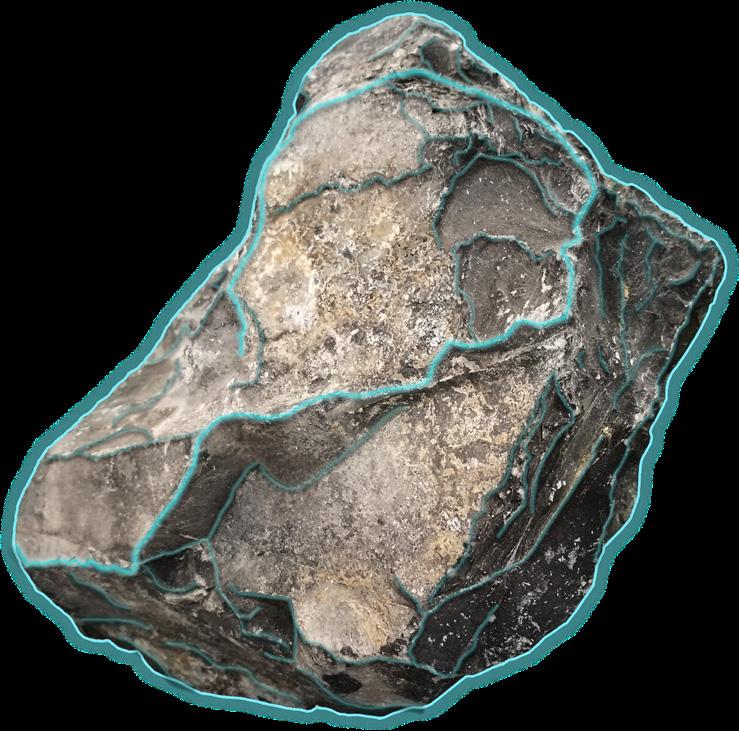
Aspects •Strong defining corner points •Profile of stone. •Prominent ridge lines and valleys lines.
Mobile device or eyewear
step [ONE] - MATERIAL SORTING

Area of maximum standard deviation used for optimization. Finding the right amount of undercuts. Grippable strength:

Vertex area of high curvature. Can work for ball-socket type connections. Grippable strength:
Strong features such as highly defined ridge lines and valleys provide data for Augmented reality tracking and recognition. Recognition strength:
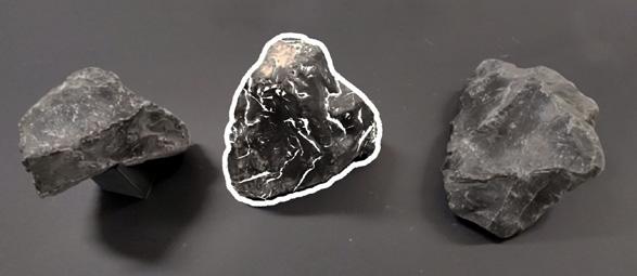
Stone profiles provides distinctive outlines that inform the data for Augmented reality Guide views for user ease. Recognition strength:
#Custom Application development
step [TWO] - PLACEMENT
Prototyping AR applications #Function 2
STEP THREE
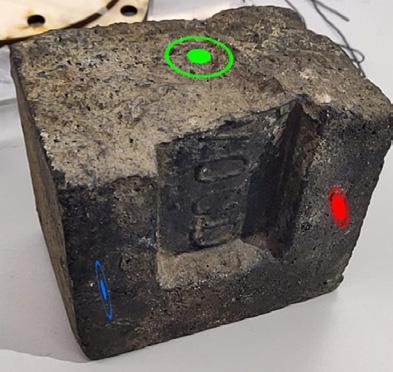
Initial prototypes indicating the connection placements by augmenting coloured dots to highlight the position of the connection, through the mobile application. Initial developments
Prototype 1 The different colours were to indicate different connections. Link: https://vimeo.com/374781597
This was straightforward when the system contained information regarding one stone and its subsequent connections. The second prototype replaced the dots with the actual connections. Highlight the exact geometry of the connections, immediate context etc. This offered a better guidance in slotting the connections onto the surface of the rock. Further developments
The black colour overlapping the tracked stone could be avoided in further developments. This was due to lack of occlusion.


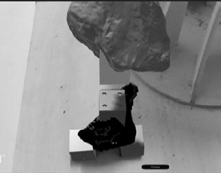
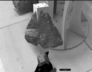
The next stone is augmented. For built structures this meant digital and physical models can be cross checked for accuracy.
Prototype 2 https://vimeo.com/374642112
STEP TWO
STEP ONE
#UI and app development for an interactive guidance system for construction
Database development
Custom database for a specific assembly.
The second prototype replaced the dots with the actual connections. Highlight the exact geometry of the connections, immediate context etc. This offered a better guidance in slotting the connections onto the surface of the rock. Further developments
With assemblies that had multiple rocks, the correct information for each specific tracked rock need to be called. This required a database that can appropriately store and call the data in a sequential manner. Model explanation
Step 1 Step 2 Step 3 Step 4 Step 5Step 6Step 7Step 8Step 8Step 9Step 9 Step N
tracking data for rock 1 (Specific #1) Guideview surface features angle/orientation recognition distance (Specific #2) Guideview surface features angle/orientation recognition distance tracking data for rock 2
(Specific #N) Guideview surface features angle/orientation recognition distance tracking data for rock N
Augmentation data for rock 1 Augmentation data for rock 2 (Specific #1) • Number of joint components • Joint component numbers • Component geometry • Connection position • next rock in assembly (Specific #2) • Number of joint components • Joint component numbers • Component geometry • Connection position • next rock in assembly
Augmentation data for rock N (Specific #N) • Number of joint components • Joint component numbers • Component geometry • Connection position • next rock in assembly
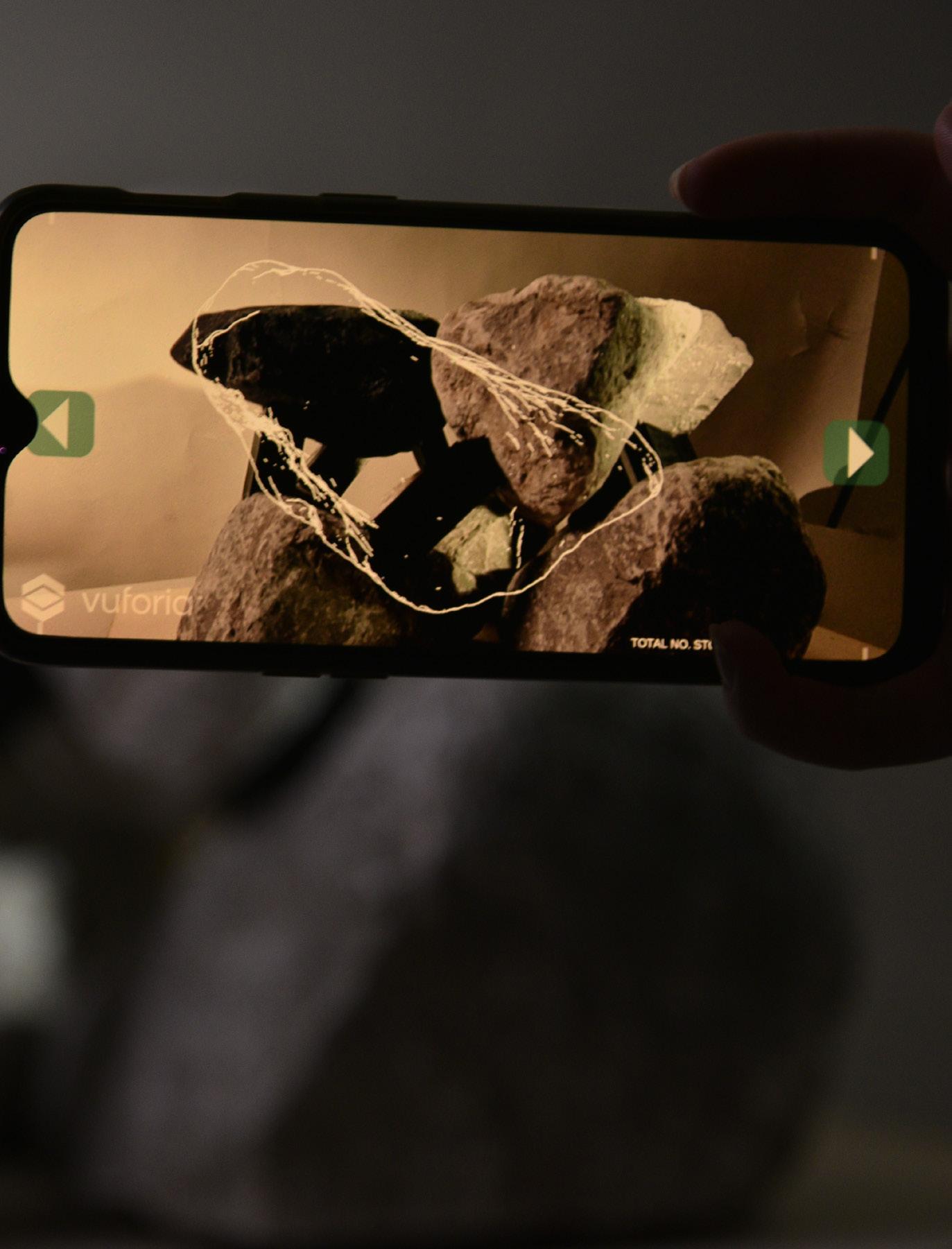
Guide View of the second rock in this as- sembly process. Once the camera aligns the correct rock face to the guide view, next layer of information will be augmented.
Choose the assembly for instructions.
With or without a guideview?
Advanced 360 allows the software to train the target model from all angles thereby eliminating the need for a guideview. This would seamlessly track the rock from all directions. However, it requires large amounts of information and decreases the performance of the application. This a new feature that requires further development.
Advanced database allows you to train a database containing multiple target models (rocks) each with one or more guide views.
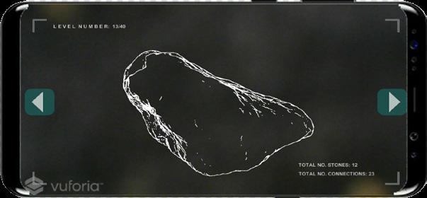
Guide View of the stone to be tracked. Displays the level/step in the construction of the assembly.
Previous and Next buttons - moves through the steps in the assembly. Display Information regarding the assembly. • Total number of stones. • Total number of connections.
ASSEMBLY 1 ASSEMBLY 2 ASSEMBLY 3

Outlook The app can include more information such as geo-locations, multiple guideviews for a specific rock. While currently this is a module for mobiles, it can be published for digital eyewear, making its easier assembly.
Scope The output would track the features to help visualize the overall architecture scale model in the context it was intended, by simply referencing to a CAD model and environment. This would facilitate more freedom in design exploration.
EXPERIENCE Key features can provide a scannable element for viewers to envision various structures in a space.
step [FOUR] - VISUALISATION OF ITERATIONS

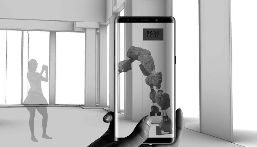
It can allow visualisation of large scale structures prior to assembly stage, by scanning any appropriate tracking material. This could enable a feedback loop during the design phase. link: https://vimeo.com/374646422


