7 minute read
SoRo Di-Fab
Tip-extending soft robots applied to digital fabrication in Architecture
Winter 2019 / Masters Thesis / Tarbiat Modares University (TMU) Supervisors Prof. Dr. Mohammadreza Bemanian, Prof. Dr. Mohammadjavad Mahdavinejad
Advertisement
Soft robotics, as an emerging and expanding field in recent years, has not only involved engineering researchers, but also other majors like art and sciences including architecture. It is simply referred to robots whose structure is mostly made of soft materials. Soft robotics projects are often inspired by nature, and biomimicry is one of the pillars of creativity in this field. Today architects take advantage of advancements in the other sciences to improve buildings construction methods.
After examining challenges in digital fabrication in architecture and considering its weaknesses and strengths, we proposed a novel method for fabricating linear free forms using tip extending soft robots. In this approach, the designer can simply fabricate any linear and curved form in real space, consolidate it with various materials, and assemble or expand it if necessary. An algorithm is developed to process the robot’s path and prepare it for implementation. To verify our results, several prototypes were made and examined with various forms and materials in the laboratory scale. This research helps lay the foundation for soft robotics digital fabrication in architecture.
The key features of soft robotics, which makes it suitable for use in architecture and large scale construction where cost, quality and time are the three most important and decisive principles, are: 1. No need to precisely define the environment (unlike rigid robots), 2. High adaptability, 3. Low cost, 4. Low complexity, 5. Low risk (compared to rigid robotics), and 6. The ability to build sophisticated and beautiful forms with simple, low noise mechanisms. Accordingly, after reviewing technologies achieved in this field, we concluded that “Tip-extending soft robots” can be used in fabricating complex forms with relatively high accuracy and low cost. In this study, we developed them to surmount aforementioned challenges and limitations in digital fabrication.
Method
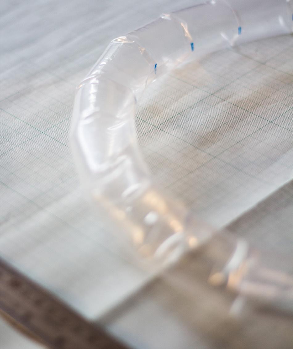
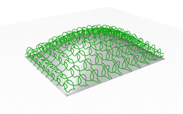
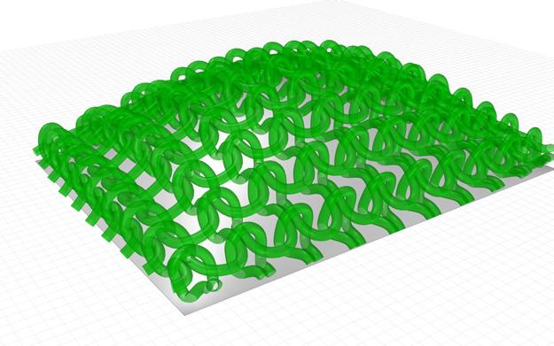
Digital fabrication procedure is divided into three general phases: before, during and after implementation. Following the main idea of kniting a nylon tube to shape a surface or a volume, we have firstly confronted the challenge of leading the tube in a 3D environment. To do so we have designed an algorithm based on tubular geometry of the inflatable nylon and defined exact positions to make a fold, so that in the if we do these folding on the tube and inflate it with air, the final shape would be similar as the on desired in the software.
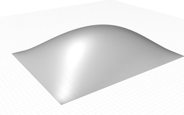
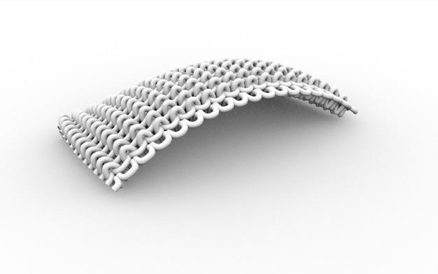
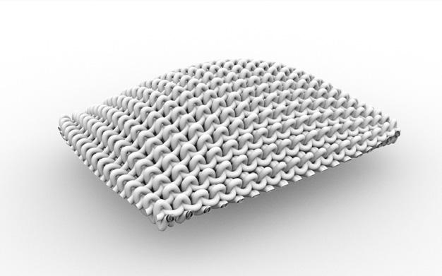
1. Creating desired line, surface or volume in Rhinoceros software
Mapping knitting 2. inspired pattern on surface and simulating path of the plastic pipe
3. Checking for possible collisions and adjusting the robot’s path
4. Unfolding the pipe path: Marking the bending points on unrolled pipe
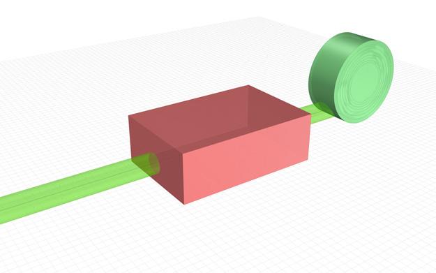
5. Folding bending points with a device or manually
6. Launching the soft robot at the project location
7. Consolidating the final structure with desired material PRE-PROCESSING
IMPLEMENTATION
CONSOLIDATION

The flowchart of the main algorithm
The processing is done in Rhinoceros software using the Grasshopper plugin and Python scripting.
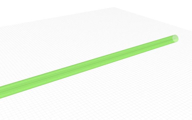
Firstly, the preprocessed linear data is received. Here, we extrude a circle (2r = plastic roll diameter) through the base curve which will eventually form the robot’s body. Then we find four imaginary axes which extend along the pipe by the Isoparametric curve logic. To find the bending points, we use guess and check method through the whole curve. The reason for choosing this method is that the existing curves are NURBS and do not have a specific mathematical equation. Therefore, it cannot be empirically concluded and the geometric method should be used Details of the algorithm is illustrated in the flowchart above.
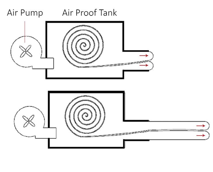
Mechanism of a tip-extending soft robot.

The basis of the methods mentioned for navigating a tubular plastic roll is to shortening one side to a specified amount at the point where the rotation is to occur. So there are two parameters that determine this issue: 1. The exact location of the rotation point on robot’s body, which can be determined by two variables of x and y. 2. Shortening length on that point, that causes rotation angle. Both of the above variables are a function of the plastic cylinder diameter, which here is considered to be a constant value.
Geometrical analysis of the tubular body.
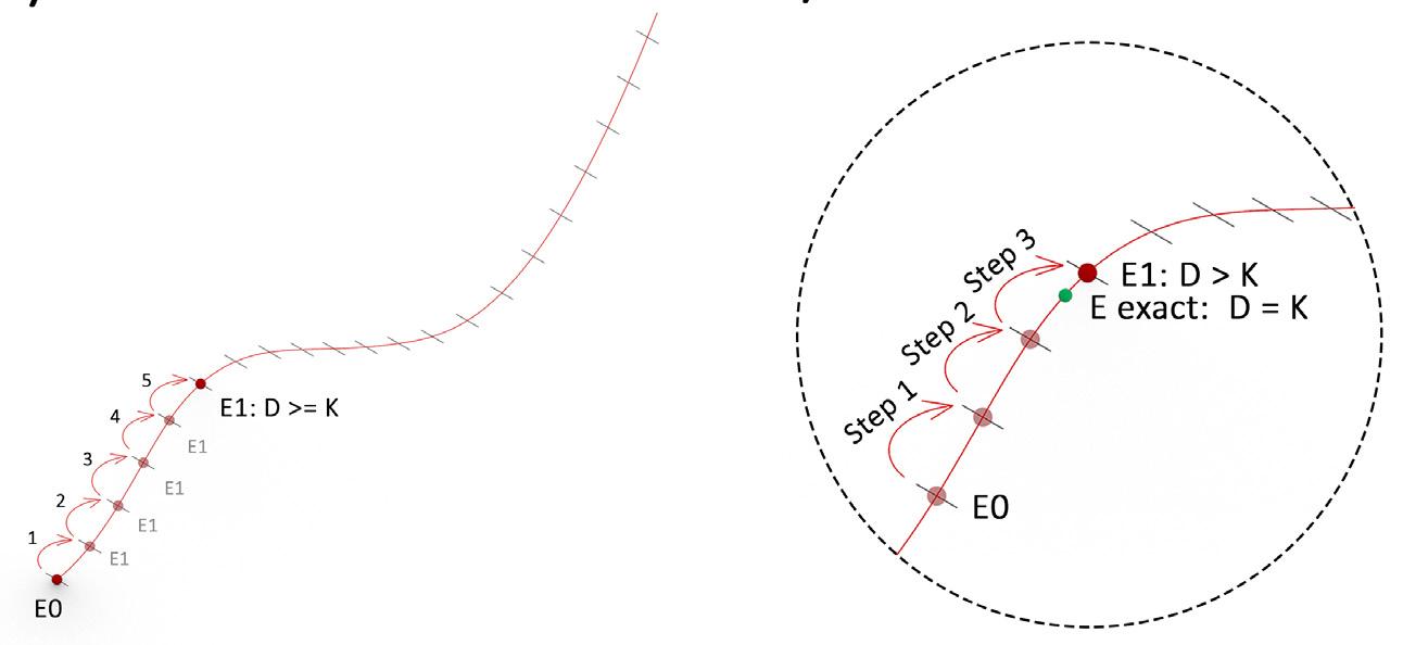
Dividing base curve to small sectors as steps. The exact bending point will be always located between two successive steps.
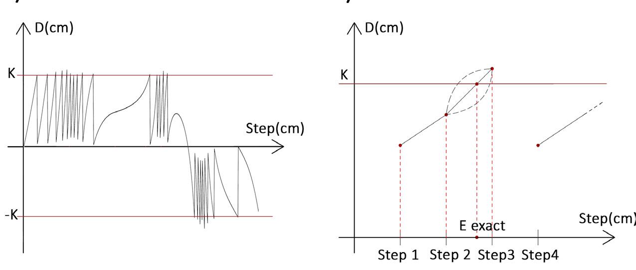
The D parameter diagram of a free form curve. Finding exact step value through interpolation.
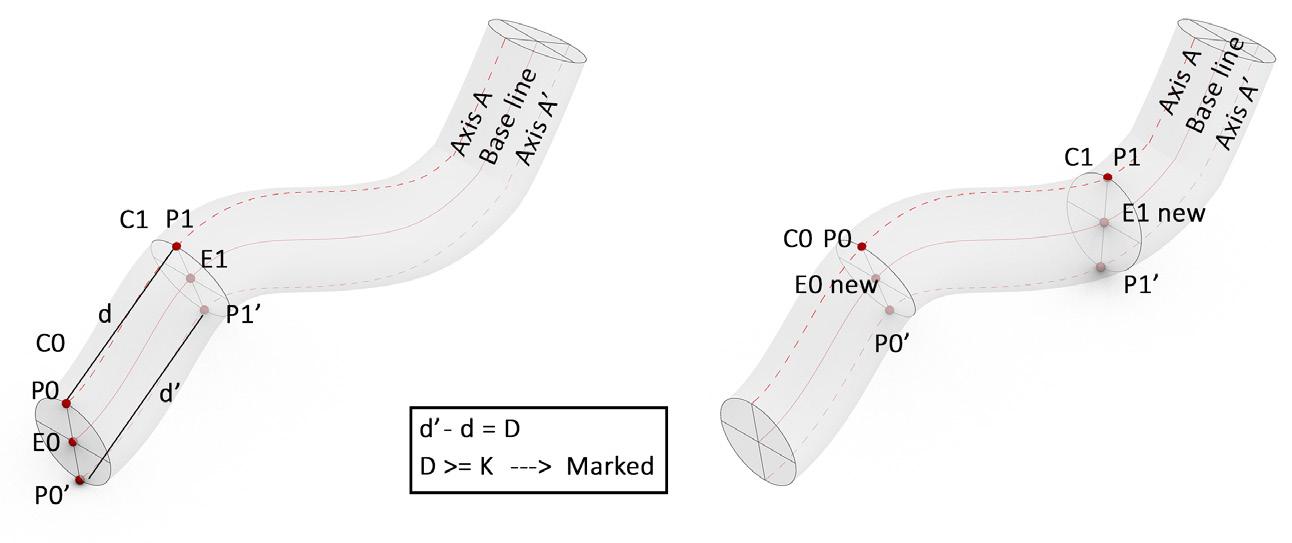
After simulation in the software, it is now time to implement the folding data on the plastic roll. The software prints out a manual guide plan, on which the bending points are marked. The user must shorten the length of the plastic roll or floding at the specified points. This can be done by gluing or by plastic pressing.
Consolidation


After initial formation, the structure reaches relative stability, which is directly proportional to the designed form. Therefore, no scaffolding or support might be provided if the form is selfsupporting. At this point there will be two options for finishing:
A. Exposed body structure: The structure will remain exposed without use of any other materials for finishing. An air compressor can be used if necessary. This method is applicable to temporary spaces. It is possible to retract the robot without damaging its original structure when needed.
B. Finishing with hard materials: In this method, before everting, the body in the air tank is stained with a type of resin with low cure time. After formation and curing, the structure gains relative strength. Lastly, we are able to cut off the compressor while the structure remains stable. Fiber reinforced composites (FRC) or reinforced concrete can also be used if the structure can withstand their initial load. In this method, a layer of tubular fiberglass or metal mesh embraces the plastic roll before launching the robot. After the formation, resin or cement can be sprayed to whole structure to strain the fiber or mesh. In this way, the robot’s body acts as a permanent mold and finally we will have a permanent structure.

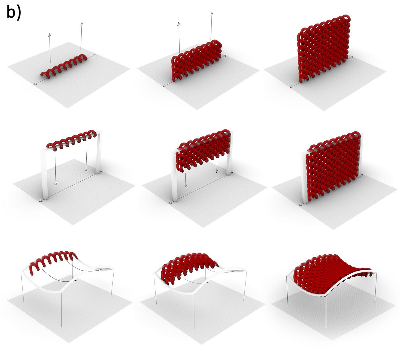
HELIX FILL ALGORITHM: Creating volume from line by duplicating helix in two or three directions. A frame can be used as a guid and the robot will fill inside with the helix algorithm.

FREE FORM CURVE ALGORITHM: The tube can follow any free curve in the space. With the use of this algorithm we can create any self standing shape.
TEMPRORY OR PERMANENT STRUCTURE
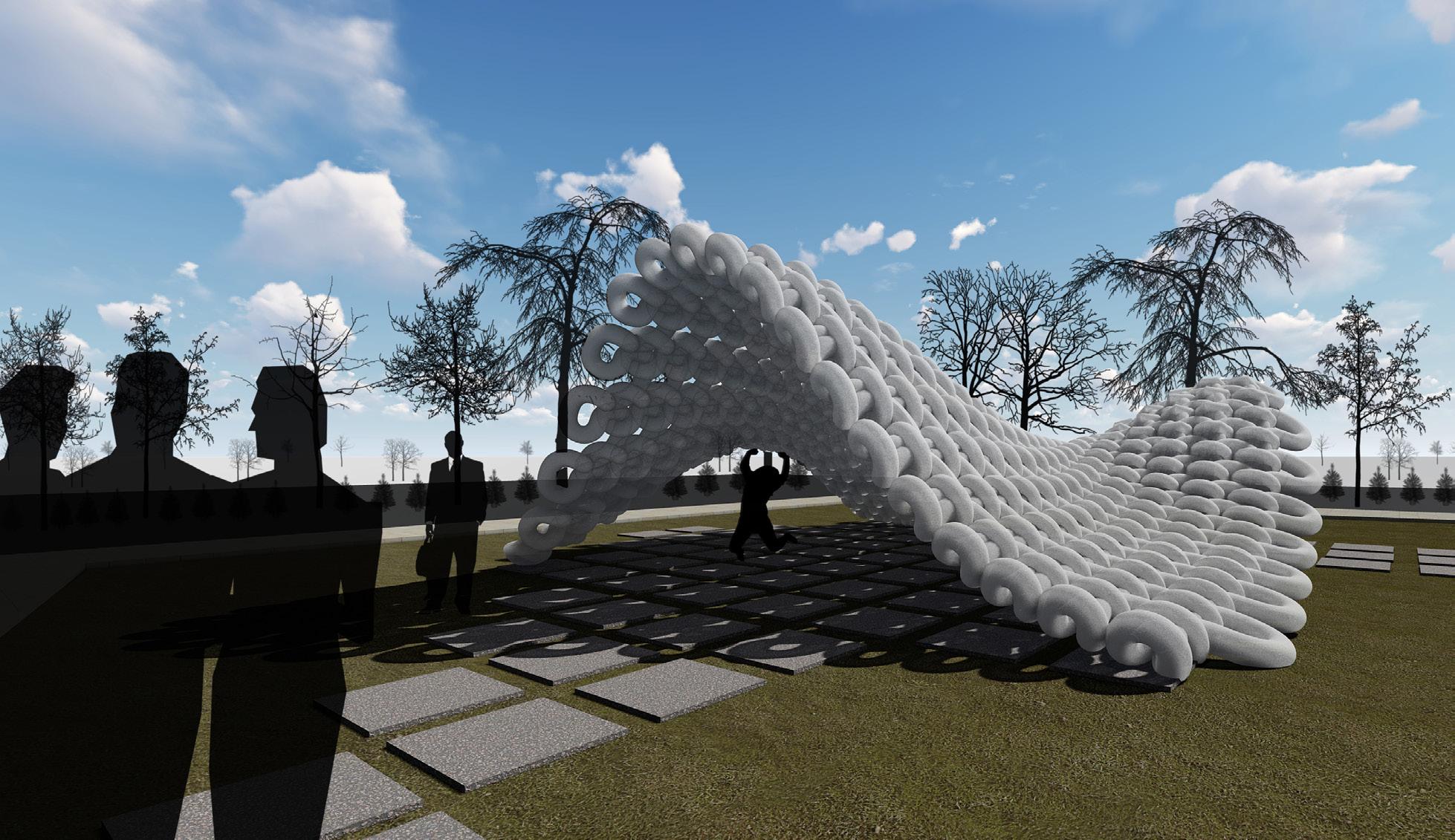
LARGE SCALE 3D PRINTING
SOFT SCAFFOLDING Different applications of the proposed method in fast, lowcost and durable prototyping and construction.
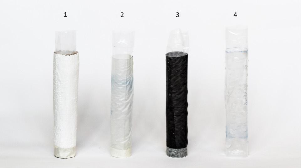
The accuracy of the proposed algorithm was verified in two parts: 2D and 3D free forms. The result of this experiment indicates that the algorithm is working properly and can be implemented manually with acceptable accuracy compared to simulations both for 2D and 3D models. Additionally, We have tested the various materials for form consolidation and tested their applicability. From these experiments, it can be concluded that the best way to solidify this type of structure is to use resin and fiber composites (FRC).
USER INPUT MODEL IN THE 3D SOFTWARE
1. Gypsum + Gunny`
2. Resin epoxy + Fiber glass SIMULATED PATH THROUGH THE ALGORITHM INFLATED TUBE AFTER APPLYING THE DEFINED FOLDS
3. Resin epoxy + Lace fabric
4. Resin epoxy only
