International Journal of Engineering and Advanced Research Technology (IJEART) ISSN: 2454-9290, Volume-2, Issue-10, October 2016
Capacitive dividers on the high voltage lines Haroun Abba Labane, Alphonse Omboua
Abstract— In the developing countries, several villages are crossed by lines with high voltage yet the populations do not profit from the electricity which passes above their heads. The classical solution for the transformation of the very high voltage into low voltage for the profit of the rural populations is expensive and is not economically profitable for the distributors of electrical energy. The voltage dividers already used like transformers in the stations, can be resized for the extraction of small quantities along high voltage lines. This single-phase technique, would plaid in favor of the reasonable costs. On the work of transporting, the high voltage line would assume the role of distributor of electrical energy to the rural populations. This article is dedicated to the detailed research of the system, for the control of the parameters of the choice equipment, for an easy dimensioning in rural electrification.
II. SCHEMA OF THE PRINCIPLE CAPACITIVE DIVIDER Line HV I C1
L Transfo MV/LV
I1 I2 F
Zn
C2 F
Ground
Fig.2: Schema of the capacitive divider
Index Terms— Extracting, Energy, capacitive dividers, high voltage lines.
The equivalent schema reduced to the primary transformer is: Line HV V1
I
I. INTRODUCTION PRESENTATION OF A CAPACITIVE VOLTAGE DIVIDER
C1
R1
xf2
I1
VΦ
R2
Io
I2 V2
For this kind of power supply, the return of the electric power being done by the ground. So, the level of the voltage of transport is reduced to a level of distribution then allowing the use of a MV/LV distribution transformer to pass from the average voltage level to that of the use. One distinguishes 3 parts associated on three voltage levels: high, medium and low.
xf1
L
C2
F
Zn xm
Rm
Groun
Fig.3: Schema of the system reduced to the primary MV/LV transformer Notations Z1 ,Z2: respectively impedances of capacity C1 and C2 Z2: impedance of capacity C2 Zn: impedance of the load to be supplied ZPO: impedance of the compensation coil ZF: impedance of the shock absorber filter Z: equivalent impedance of the network subjected to the medium voltage V2 R1: Resistance of winding of the primary transformer R2: Resistance of winding of the second transformer Rm: Resistor losses by iron in the magnetic circuit of the transformer Rp: Equivalent resistance of the transformer (reduce to the primary) XF1: Reactance of winding of the primary transformer XF2: Reactance of winding of the secondary transformer Xm: Reactance of magnetizing the MV/LV transformer V1 ,V2: respectively voltages of poles capacity C1 and C2 V: Single Voltage of HV Line Un: Nominal voltage of the load Zn Sn: Apparent power of the load cosφ: Factor of power of the load Zw = Z-Zpo α: Real part of Zw
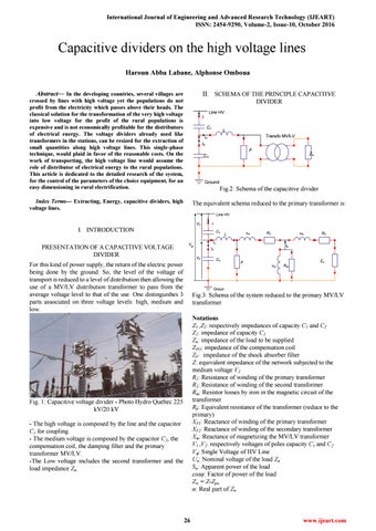
Fig. 1: Capacitive voltage divider - Photo Hydro Quebec 225 kV/20 kV - The high voltage is composed by the line and the capacitor C1 for coupling. - The medium voltage is composed by the capacitor C2, the compensation coil, the damping filter and the primary transformer MV/LV. -The Low voltage includes the second transformer and the load impedance Zn.
26
www.ijeart.com