

Work samples | AA Project | Other works


2 1
BIOCOMPOSITE STRUCTURE AND LANDSLIDERESPONSIVE DESIGN


TOWER DESIGNEMERGENCE AND EVOLUTIONARY COMPUTATION


3
OTHER INDIVIDUAL PROJECTS IN DIFFERENT SCALES AND TYPES

4
WORK SAMPLE


1 Biocomposite Structure And Landslide-Responsive Design Re-Myce
Project Type
AA EmTech Thesis | Group Work Location Yunnan, China
Role
Morphology design | Physical experiment| Structure system


From the gathered data and information above, we've mapped out a preliminary plan that aligns with both human needs and environmental constraints.


1. Urban planning by using Evolutionary Algorithm (EA) to select the site location and different types of buildings' area
2. Regional planning by using Cellular Automata (CA) to find the exact location of residential architecture and green land area
3. Morphology design (EA & c#) on the base of Planning parts
4. Structure system and material physical test(EA & c#)
5. Landslide simulation and structure details (Houdini & FEA)


The team iteratively generated the floor plans based on the spatial magnetic relationships and properties, all combinations of grids as boundary floor plans are iterated for 900 generations.
All of the convex corners of the morphology were connected so that all of the vertical corners of the building were larger than 90 degrees in order to more easily divert landslide
Morphology in this step, we have data from the Urban and regional planning, such as housing areas, green areas, contour lines at 3-meter intervals, and water flow simulation lines. We mainly deal with the housing area, first we divide all the grids into different clusters, the number of grids in the clusters is from 2 to 5, which corresponds to 50 square meters to 125 square meters, and 60 clusters which is the number of existing housing units. and the grids will be formed into different combinations with the change of k-means clustering SEED.


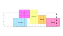


This is a library of all combinations of 2 to 5 units and their corresponding floor plans and morphology, which is equivalent to a dictionary whose indexes are combinations of units and whose indexes correspond to morphology.Each time the seed of the K-means cluster changes, the program will traverse the dictionary to find the matching clusters and replace the corresponding morphology to the position of the clusters.


Step 1: K-means clustering by seed


Step 2: Iterate through all the clusters in the dictionary to find all the shapes present in the site


Step 3: Morphology Result output Corresponding morphology is replaced to the position of each cluster

This diagram illustrates this substitution process in more detail. If the clusters in the field have the same shape as the clusters in the dictionary but different angles or mirrors, the same mirrors and rotations are performed to maximize the replacement of the morphology according to the position of the clusters.


Fitness Objective 01
Angel between flowlines and buildings close to 180° Divert landslide/Mitigate landslide effects

Fitness Objective 02
Minimize the differences in quantity of buildings To distribute the number of different types of houses equally

Fitness Objective 03
Infrastructure building area close to 425m2
The size of the infrastructure is closer to siteneeded

Gene 01
K-means clustering seeds

Gene 02
Rotation angels for infrastructure

Gene 03
Rotation angels for 2 units buildings

Gene 04
Rotation angels for 3 units buildings

Gene 05
Rotation angels for 4 units buildings

Gene 06
Rotation angels for 5 units buildings

Fitness objectives 01 3282.18°
Fitness objectives 02 19
objectives 03 3


Based on the above three fitness criteria we performed a evolutionary algorithm to find an individual that can relatively balance our three objectives. The result we chose is not the best value for a single criteria, but it is the closest optimized and balanced result, and of course avoid some extreme results.

The team introduced Evolutionary Algorithm for diverting landslide by rotate each building to maximize the angle of the water flow simulation lines to be close to 180 degrees, this is the fitness objective 1. Fitness objective 2 is to control the number of individual TYPES so that this number is distributed more evenly and reasonably; Fitness objective 3 is to control the total number of square meters of infrastructure closer to the 425 square meters required by the site.


Landslide simulatin to get the size range of beam and column


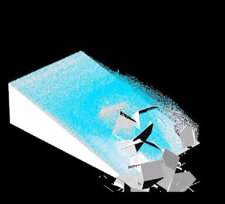


The team utilized rigid body dynamics simulation to determine a size range for the building's protective structures. They then employed a multi-objective algorithm to optimize and ascertain an appropriate size, as detailed in equation1.
����! =17.248KN/m³ ℎ! = 1.8m ����! =9m = 75° G =gravity(9.8N/kg)


between the facing surface of the building and the direction of the landslide
The team started by simulating landslides on the site to derive the areas where the buildings would be affected and classified these areas into high, medium and low risk zones. The team then selected one of the buildings as the paradigm based for generating the façade for the protection of the building.
To generate the façade system for the protection of the building, a finite element analysis of the building was carried out to analyse the areas of the building that had experienced relatively severe displacements and to obtain the principle stress lines, and then the distribution of the principle stress lines was observed to determine the distribution of the sandwich panel of the façade based on the sparsity of these lines.


Landslide simulatin to get the size range of Sandwich Panel


From simulation results, rigid and flexible protective structures with column and beam sizes less than 20cm lead to complete building damage from landslides. Sizes over 60cm prevent damage, but further increases don't enhance protection.


Landslide simulatin to get the size range of Sandwich Panel


In flexible protective structures, when the width of panel is less than 0.4 metres, the building will be completely damaged, but when it is greater than 1.4 metres, the building will not be damaged, and there will not be much change if its width is increased again.

Structure optimization
In order to use less material while allowing less displacement to occur when the building is impacted by a landslide, the team inputs the resulting range of dimensions into an evolutionary algorithm for iterative optimisation, which then produces the dimensions of columns, beams, and sandwich panels.

Optimization result: Displacement of different structural dimensions under the force of landslide
FC1 Rank 1 (G5 I6)


1 4
2 3


Material Usage: 43.72m3 Panel Scale: 1m Displacement: 5.49cm Panel Thickness: 0.3m
FC2 Rank 1 (G13 I0)


2 3
1 4


Material Usage: 27.97m3 Panel Scale: 0.6m Displacement: 17.92cm Panel Thickness: 0.3m
Further Selection
The Pareto front solution shows the optimization of EA , because of the smaller number of genes and optimisation objectives, the differences among the optimized solution are subtle, but it still causes the vast different impact under the water flow.
INDIVIDUAL


Material Usage: 31.02m3 Panel Scale: 0.6m


1m


9.57cm
Thickness: 0.25m

14.08cm
Thickness: 0.17m
We selected four representative optimization results for landslide simulation: optimal FC1, optimal FC2, the average of FC1 and FC2, and the relative objective differences. After simulation, the average of objectives proved most resilient to landslides.

Assembling and Detail
In terms of the assembling process, The sandwich protective envelopes are composed of modular components, and these components are installed into a customisable frame structure for dismantling and installation. The connecting and framing parts are made of steel, and the layers of these modular components can be stacked and dismantled according to the user's actual needs and changing environment.
5

Protective Envelope Map 1

Medium Risk

2 Pile Foundation
Platform

Inner Wall
3 Sandwich panels: Mycelium Composite Blocks


4 Outer Planks


Windows
Doors


6 Roof Panels


2 Tower Design
Emergence And Evolutionary Computation
Project Type
AA Course Work | Individual Work Location Chicago, U.S.
1. First Evolutionary Algorithm(EA) to find morphology
2. Get multiple individual results from first EA
3. Narrow down the domain of genes which set to control morphology by comparing original gene domain with pareto front gene domain
4. Creating facade system of the morphology
5. Add new genes and set new objectives for facade and run second EA combined morphology and facade
6. Selecting the final result with some strategy and modeling the structure system and some details


Fitness objective 01
More connectivity between buildings

Site
N Radiation figure indicates that the north park gains more sunlight than the south part. and Windrose displays the main wind direction at the site is south-west.
This data was crucial to recognize the particular environmental conditions of the site and to further develop the tower morphology and facade.

Fitness objective 02
More density

Fitness objective 03
Less shadow of the background in winter

Fitness objective 04
Sufficient roof garden
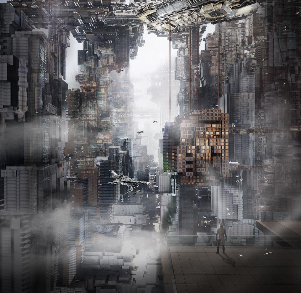
Generate an urban block with buildings that address Chicago’s current high population density. The morphology should have the less wind effect and better energy-saving and thermal insulation performance. Also the public green space and roof garden should be introduced to rich the living experiment.

Gene pool Pareto front gene domain
Gene 1: Position of point
Gene 2: Height in 1 base
Gene 3: Height in 2 bases
Gene 4: Height in 3 bases
Gene 5: Height in 4 bases
Gene 6: Height in 5 bases
Gene 7: Height in 6 bases
Gene 8: Height in 7 bases
Gene 9: Height in 8 bases
Gene 10: Scale in X
Gene 11: Scale in Y
For multi-objective genetic algorithm, Pareto Front is one of its results and one of the selection strategies. We can see from this that based on the distribution of the three FOs in Pareto front, and can further analyze to get the optimal solution under different conditions


STEP 3: SECOND SEQUENTIAL EA (SET-UP AND RESULT)

Fitness objective 01
Less shadow of inner slabs

Fitness objective 02
Higher skeleton density


The two fitness objectives of the second EA are to increase the radiation inside the building and to increase the skeleton's density because the skeleton's density will affect the building's overall structural strength. However, it is challenging to access karamba3d into the EA, but it is possible to use this simple method of FO2 to form a conflict with FO1 to optimize it better.


After getting the results of the second EA, selected the average individual of the two objectives (minimize material for skeleton structure and maximize the density of skeleton structure) and continued to design the individual with in-depth details, including the floor slab, core, and internal frame structure, and verified it with FEA analysis. Although this design level differs from the fineness and reasonableness of the actual project, it can provide a new way of thinking for future projects.


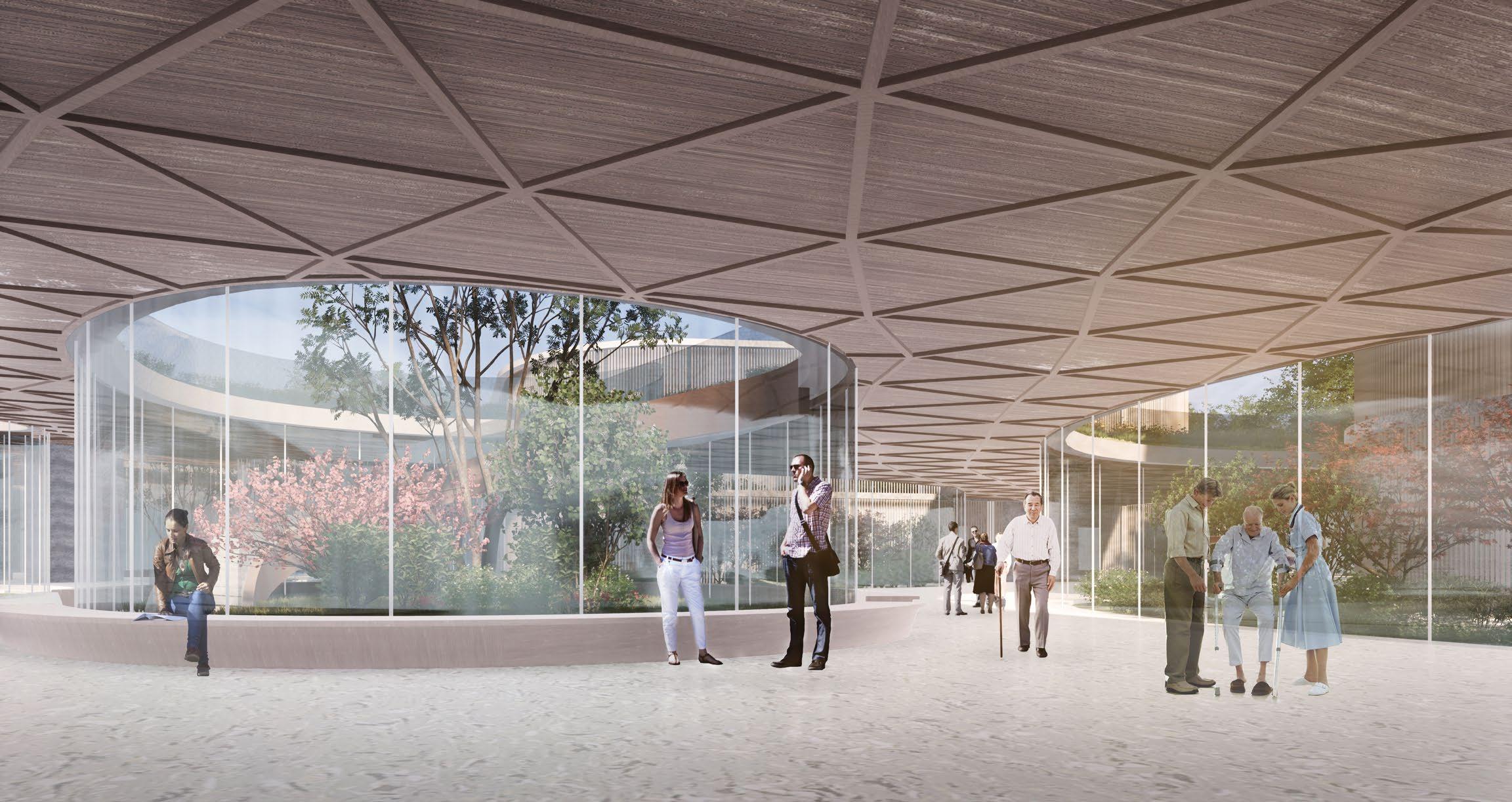
Since the outbreak of COVID-19 in the world, people's lives and hospitals have been more closely linked than ever before. No matter the scare of the epidemic situation, or the repeated detection and treatment, the cold image of hospitals lingers on. This case explores a more ecological and gentle hospital environment, which brings a little warmth to the hospital at the moment of high frequency use.
Spain was one of the most serious epidemic countries in Europe at the time of the outbreak, and its medical system was once facing collapse; This case is located in the southwest of Barcelona, through the study of Barcelona city texture, as well as the surrounding architectural form, the final prototype of this case.
According to the functional requirements of the plot, three large entrances are set directly facing the road, and the necessary separate openings for different functional buildings will be set accordingly.


Gyroid domain=(-1,2) v=0.3

Gyroid domain=(-1,1) v=0.3

3Dscale=0.5

Gyroid domain=(-1,1) v=1.3

Gyroid domain=(-1,2) v=1.3
4 8m 4 8m
4 8m

PW Hyibrid domain=(-1,1.6) v=0.6

PW Hyibrid domain=(-1,1) v=-0.5
Project explores minimal surfaces, dismantles and reconstructs them, exploring spatial potential through regenerative techniques. Scaling surface height appropriately and transitioning from closed to open and back creates rhythmic spatial experience.


2015 ~ 2019 Changsha, China


2019 ~ 2021 Shanghai, China


SiHe School

4.1 Primary School
Project Type
Competetion
Role
Time 2020
Site Area 30298.9 m2
Location Luoyang, China
Master plan | Modeling| Rendering | Communicate with other displines and clients
Mountain Academy, the architectural design draws on the imagery of mountains and courtyards, inserting courtyard-like school spaces between the functional interior spaces and the experiential rooftop park.
The basic architectural spaces consist of a combination of standard classrooms and multifunctional classrooms.
The cluster surrounded by four central courtyards creates a well-arranged open activity space.


Master plan 1:100

The project is located within the original industrial park.
By elevating the building blocks, the architecture is integrated with the green spaces, creating elegant and highly recognizable buildings.
Role
Master plan | Modeling| Rendering | Communicate with other displines and clients
It aims to develop a multifunctional community complex, reshaping an important node of public relations within the park.


Sections 1:100


4.3 Pavilion
Bajiaohe Park
Role
Master plan | Modeling| Design development | Communicate with other displines and clients
This project fosters a rich spatial structural relationship within the architecture as well as between the architecture and the landscape.
By aggregating the architectural layout, it enhances the popularity of the site and supports business operations.
It creates a unique architectural image, forming a lasting spatial memory.

The project utilizes the elevation differences of the site to arrange various spaces, thereby creating open landscapes and forming an organic system among environmental, leisure, and


4.4
Star City West Area
Mixed-Use And Office
Project Type
Commision Site Area 33733 m2
2017
China
Role
Concept design | Floor plan | Diagram | Digital models | Sections | Report files | Design development
This project is located to the north of another residential project and is part of the real estate development of Futian Zangjun.
The project fully exploits the existing land resources, analyzes the value of the land, and introduces diversified and applicable commercial businesses, focusing on creating a neighborhood commercial body with innovation and convenience.
Master plan 1:100


The project is the planning and design of the headquarter office building of Friendship&Apollo Corporation.
Project Type
Commision
Role
Time 2018
Site
Area 6694.34 m2
Location Changsha, China
Design development | Floor plan | Diagram | Sections | Report files | Communicate with other displines
Ground Floor Plan 1:100
Due to the site constraints and the influence of the surrounding environment, two towers are arranged in the base, one main and one auxiliary, connected by a podium in the middle. The pattern of twin towers also makes the façade of different heights and reflect each other, effectively relieving the sense of oppression to the neighboring buildings.
1-1 Section
Project Type
Commision
Role
Time 2019-2021
Site Area 257,255.36 m2
Location Shenyang, China
Master plan (for client and government) | Floor plan| Present to clients | Communicate with other displines and clients | Design development | Detailed drawing
The project contains multiple sites:
Zone A: commertial
Zone B: Residential with commertial: 38289.33 m2
Zone C: Residential with commertial: 97581.17 m2
Zone D: Residential with commertial: 61782.62 m2
Zone F: Residential with commertial: 59602.24 m2
The design of residential plots focuses on maximizing the use of space within each size of room, making the project more cost-effective than the surrounding residential competitors.
4.6 Residential | Community Center | Kindergarden
Wanjin Red Tree, Zone A To F
Project Type
Commision
Role
Time 2021
Site Area 47126.06 m2
Location Shanghai, China
Master plan | Floor plan| Design development | Communicate with other displines and clients
The project is located in the heart of Jing'an District, Shanghai, and is surrounded by a number of important tube stations, which makes it the center of the city's prosperity.
The commercial type is restaurant and retail, in accord with Suhewan's eastern area, which is mainly international business, culture, leisure and residence. Leisure and residential-oriented functional positioning; located in the area, commercial value premium is relatively high
Master plan 1:100
Underground Garage Entrance Section 1:100
4.7 Mixed-Use 3# Shuhu Creek
Role
China
Master plan (for client and government) | Floor plan| Present to clients | Communicate with other displines and clients | Design development | Detailed drawing
The project is located in Huanggu District, Shenyang City, covering an area of 31,000 square meters, with a total construction area of 102,700 square meters, of which buildings 1# to 5# are high-rise residential buildings with a floor height of 2.9 meters; building 6# is for business and property; building 7# is for supporting facilities;