ANTONIO . HEATH

Selected Works
2021 - 2023


Selected Works
2021 - 2023
Spring 2023: Architectural Design II
Instructor: Keith Plymale
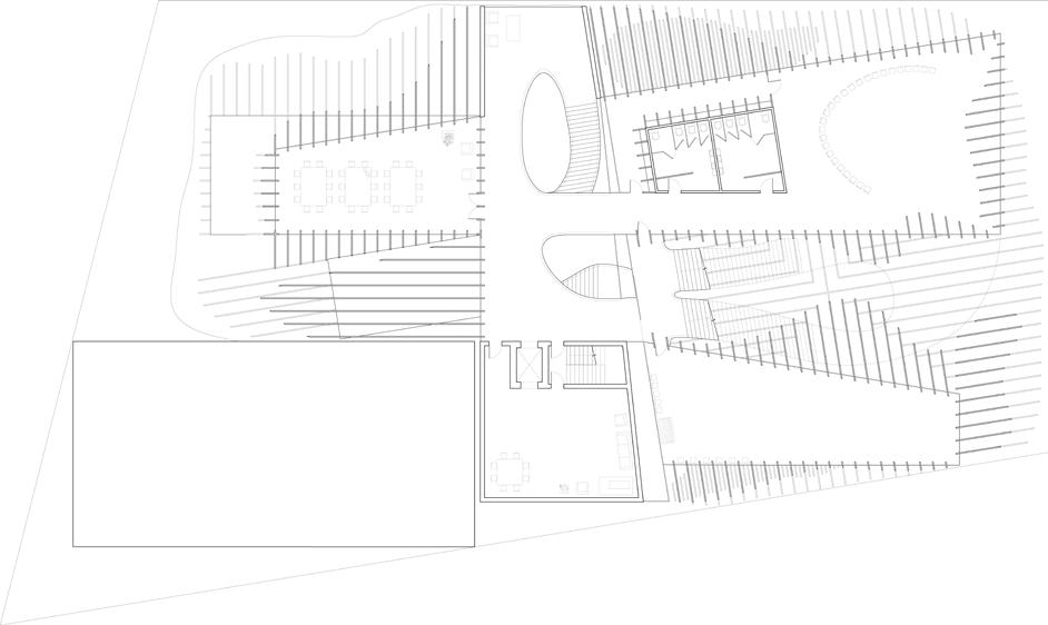
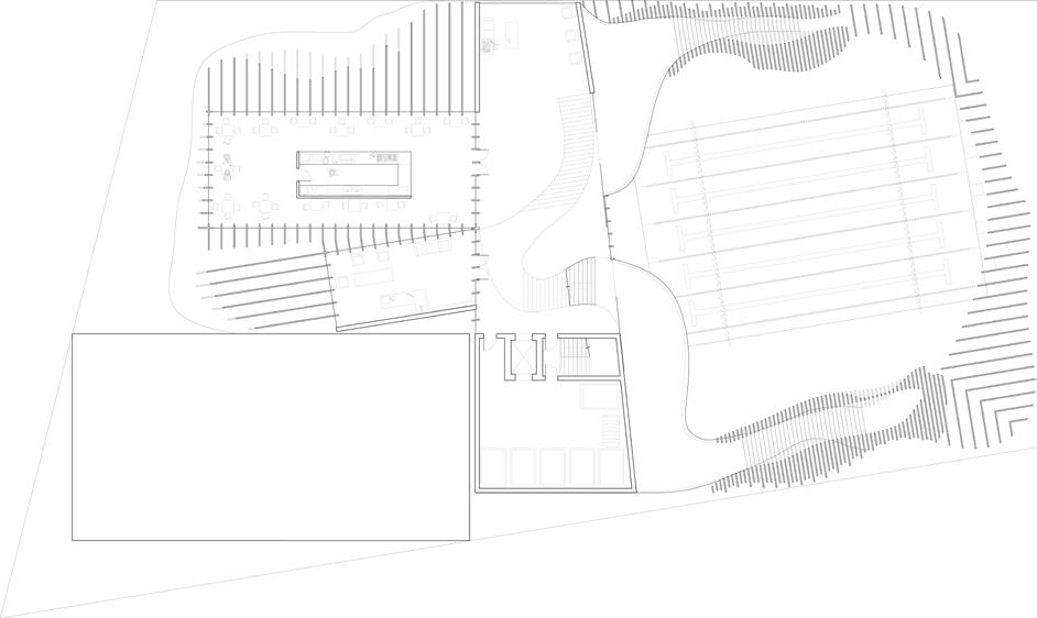
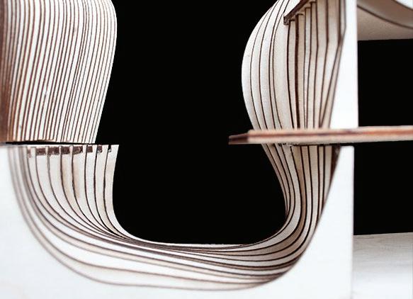
The Rec Center, located in Oakland, CA hosts multiple recreational ac tivities: a 25 yard swimming pool, a bouldering gym, a dance studio, and a yoga studio. The intent of the project was to have these programmatic elements have a direct link to the building’s physical structure. Both the appearance and spatial impact of the structure tie into the free-flowing nature of the recreational program. Inner spaces are defined by gener ally rectangular geometries in alignment with the surrounding context. These boxes are engulfed by a structural logic of undulating planes. These fixed planes, which appear like massive exterior fins, collectively create an amorphous shape which generates movement in harmony with the recreational activities. The structure goes beyond a merely metaphorical argument, as the fins’ curvatures dynamically filter natural light through out the project, as well as laying out a grid for the inner geometries.
The interior boxes serve as dance and yoga studios, community spaces, offices, a cafe, and more. As these box-like spaces plunge into the larger amorphous shape, they are left undisturbed by the fins, creating clean rectilinear cut-outs within the structural system. When they emerge, the curvature of the amorphous is threaded into the boxes by flipping what is read as solid (the amorphous) into void and vice versa. This relation ship between amorphous and box comes into fruition from the second floor up, as the base is ruled almost entirely by the organic structure. At the base, the amorphous lifts off the ground, creating two cavernous bubbles. These two caverns hold spaces for the boulding gym and the swimming pool. On the north and south sides of the pool, two respective sets of the stairs run through the “walls” of the cavern, lofted by more closely spaced fins in perfect alignment with the stair treads. Fins around the pool, which generally are spaced into three foot increments, occasion ally widen into six foot increments allowing easy access between the space and the street. The alternate cavern, however, becomes completely solid, allowing the walls themselves to be the area for climbing.


East-West Section






Fall 2023: Architectural Design III: Golden Mud
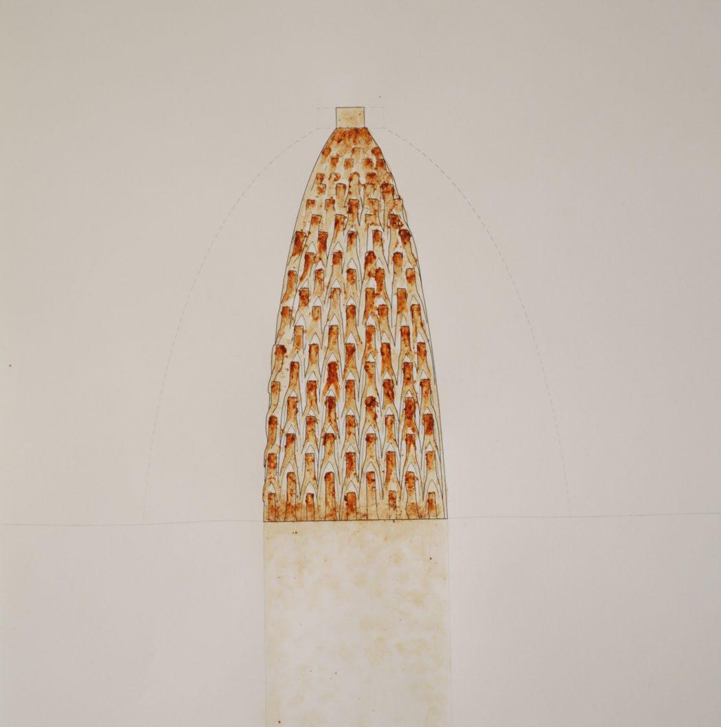
This project is an artist residency and public gallery located in Rio de Janeiro, Brazil, north of Copacabana Beach in Leme. The site sits just between the highrises along the beach to the south and a favela to the north; an area where mud architecture has precedence. The project is constructed using cob from local mud. Additional materials are used including wooden floor panels, boards, and joists, as well as concrete foundations. A natural lime-based coating would be used to limit damage from the elements. The residency’s art is focused on large-scale sculpture as a medium. The project consists of nine units, varying in size. Five units are individual apartments for the artists, while the other four include common spaces for residents, public restrooms, administration, and mechanical and janitorial spaces. Like pieces in a sculpture garden, the units are arranged to encourage movement between and around them. A broad pathway or avenue stretches across the middle of the site, from east to west. Each apartment includes a basement studio space which opens onto the central avenue in response to the steep topography of the site.
Instructor: Maria Paz
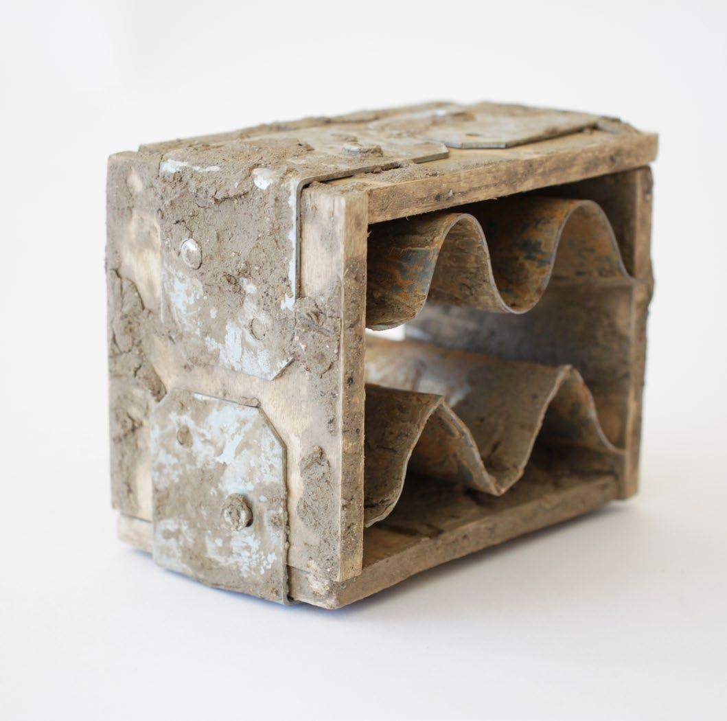
The units’ concrete foundations utilize rigid rectilinear geometries, and then embrace the flexible materiality of the mud by stretching and twisting upwards via multiple large skylights. All nine units include these oculi which bring natural light into the cool interiors in desired locations. The units were formulaically created with initial rectilinear bases directing the substructure of geometries and interior oculi “targets”. Based on this, the oculi rise up towards the sky with a heliotropic approach in order to maximize light through relatively limited geometries. The foundations and relative positions and orientations gave way to unique forms for each unit. In light of this, the nine units not only were organized in mimicry of a sculpture garden, but became pieces of sculpture amongst the art themselves. In addition to cob, other mud construction methods were studied and compared including adobe bricks and wattle and daub. Research was conducted via an array of contemporary and vernacular precedent studies, clay models, and ½ scale cob and adobe 1’ x 1’ wall segments using local Bay Area mud and straw.



Instructors: David Jaehning & Cecilia Egidi
Collaborators: Chanel Fiegen & Oceane Ignatov
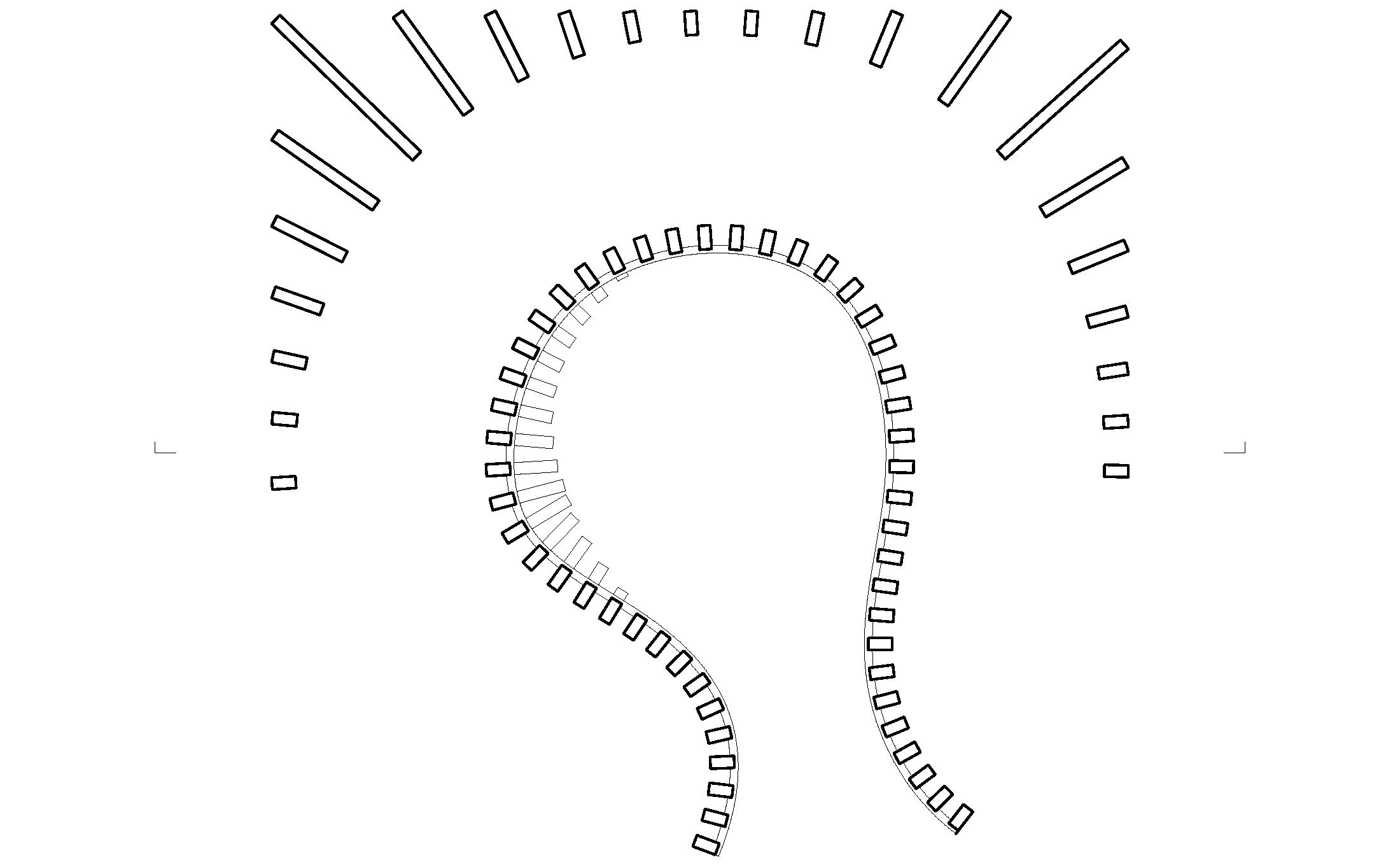
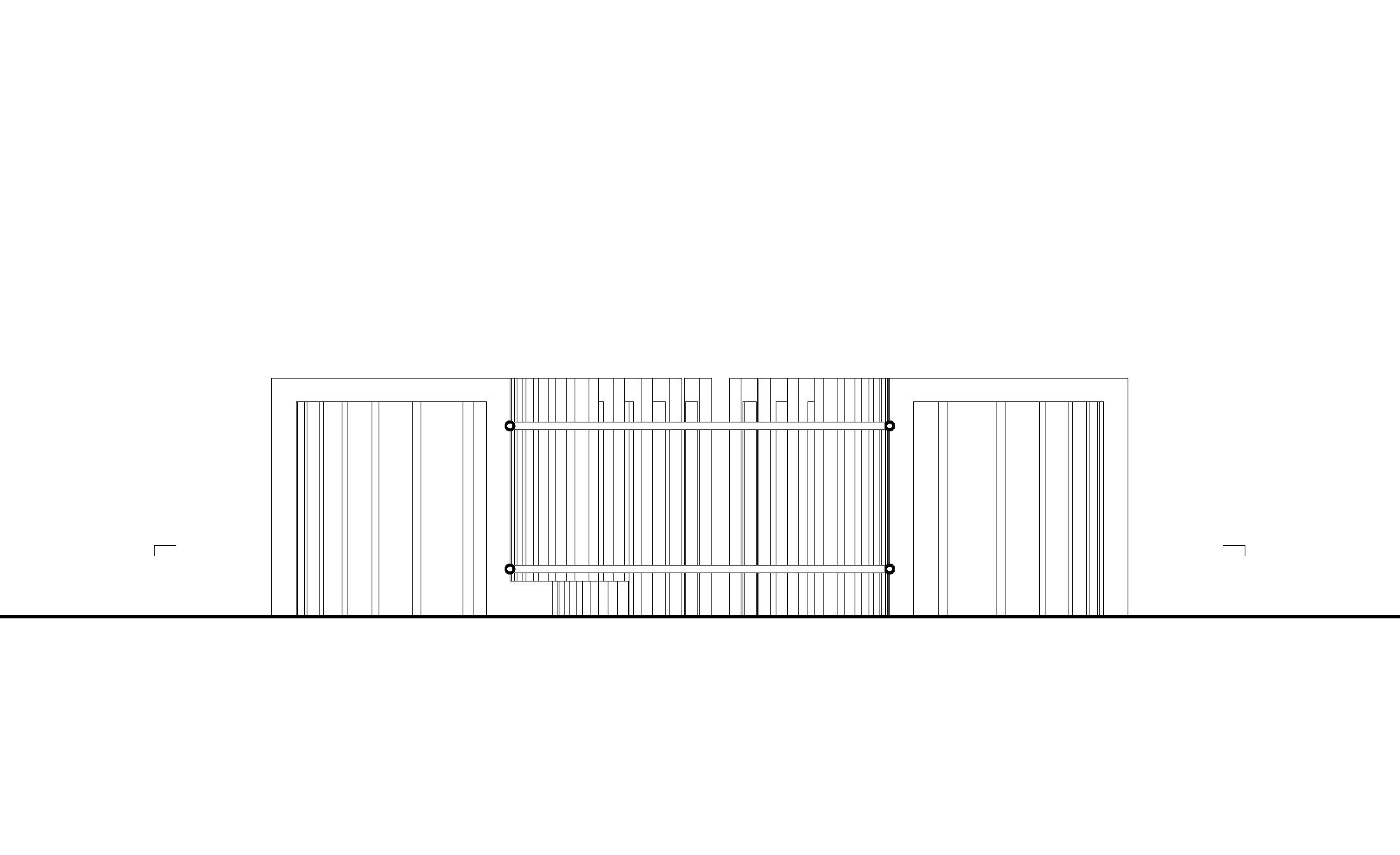
The steel pavilion, nicknamed “Splitting Spaces”, takes the initial ideology of bar grate. Unlike traditional bar grate, the structure follows a pair of curved crossbars rotated ninety degrees into a vertical orientation. Rather than forming a walkable surface, the bearing bars rather serve as vertical fins. Extruded outwards at varying depths, they create the edge of a rectangular form, with a free flowing path cutting through this defined solid. The angle of each fin is defined as being perpendicular to its intersection with the void. The fin pattern tapers and dissolves away around the two “ends” of the path. Save these two end pieces, members are carved away to form the impression of an enclosure. Despite the single stroke trajectory of the path, movement between and around the large fins allows for more tangible experiences with the project. The pavilion’s overall form generates a central courtyard, which includes a bench for patrons to sit and relax. The sandy base of the model brings warmth into the pavilion to contrast the cool reflective materiality of the steel fins.
The project proposes that the bearing bars would be precisely welded to the swaying cross bars on site. Individual materials would be manufactured offsite. The curving cross bars are to be custom made offsite, likely in segments. The specified bearing bar dimensions are to be factory generated and cut.


Instructors: David Orkand & Elliot Kwon
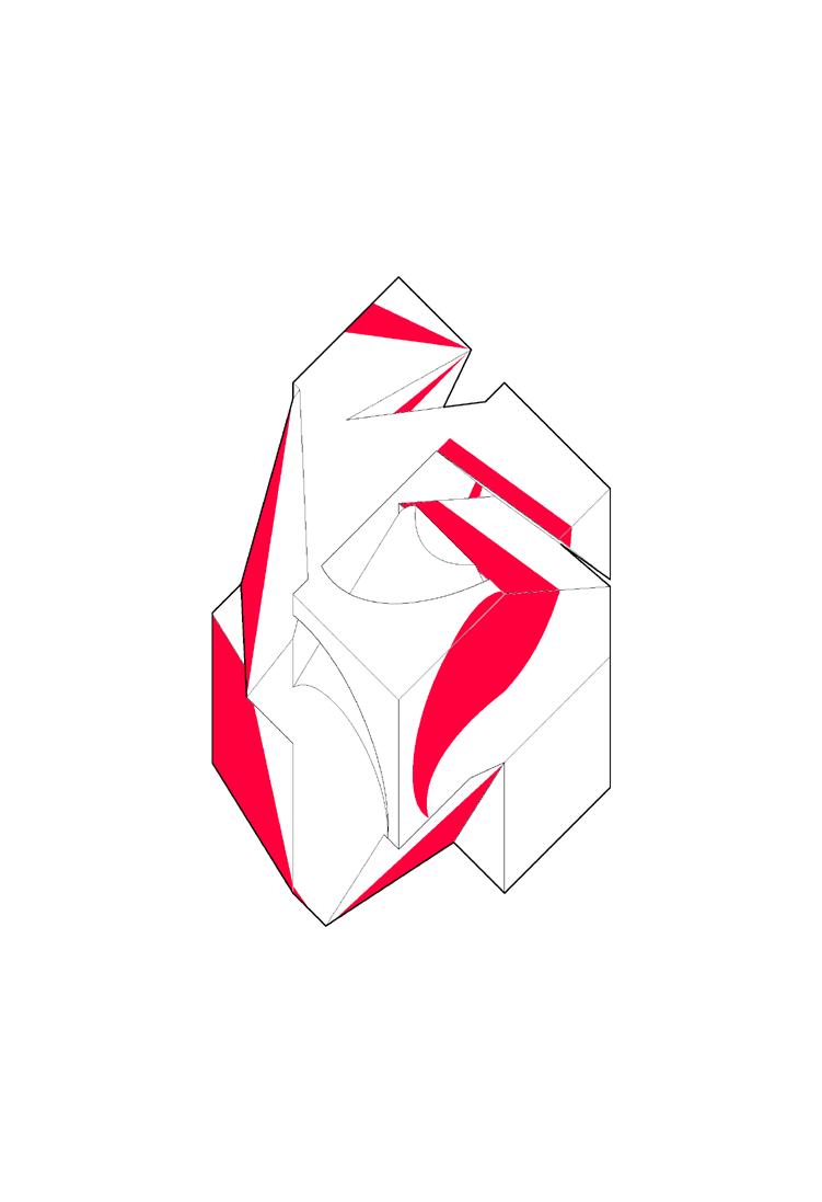
This project and studio lays focus on understanding three dimensional forms through two dimensional drawings. To begin, a 4” x 4” cube was drafted by hand, rotating it through orthographic projection. Choosing a specific auxiliary, a subtraction was made from the solid. The cut was then tracked back through each surface view. Next, the same process was repeated with a secondary cut in a new location by shifting the material through color, rather than voided subtraction.
This process was done for a total of eight cubes, using a variety of methods including single cuts, curved cuts, and faceted cuts through primary, secondary, tertiary, quaternary, and quinary auxiliary views. The eight modified forms were then compiled into a larger 8” x 8” cube, intending to create an object which could be seen as aesthetically interesting from every side, edge, and corner.
For the second phase, all coplanar surfaces from the 8” x 8” cube’s bounding box were removed, leaving only the internal surfaces, or the remnants of cuts from the original cubes. These angled, curved, and faceted surfaces were then given thicknesses of either 0.5” or 0.25”. Color shifts from the previous iteration of the project were abandoned in order to give primary focus to form.
For the final phase of the project, the collection of thickened surfaces were placed inside of a 16” x 16” bounding box. What were initially detatched and floating surfaces, were subsequently extruded and edited in considered ways. As planes merged and collided, a single conjoined architectural anatomy was fabricated. This form was then provided a scale of 1” to 1’, creating a pavilion-like structure with different slot openings, triangulated entrances, and integrated stairs.



 Projection Compilement
Internal Isolation


Instructors: Rudabeh Pakravan & Avery Lakeman
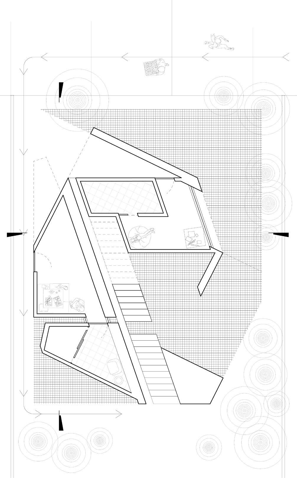
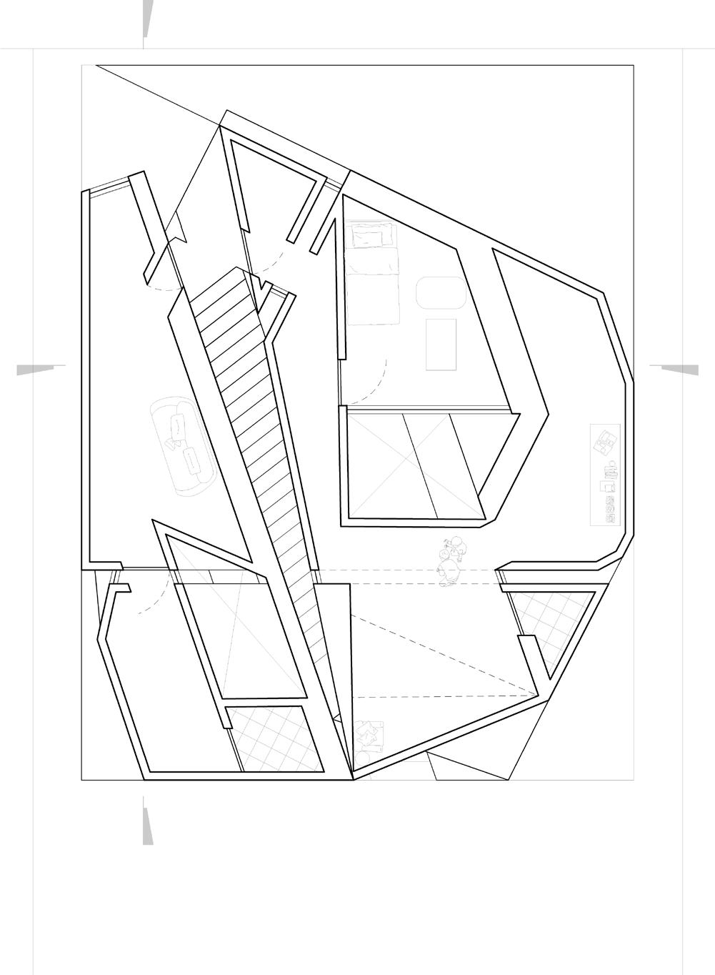
The duplex is located in an empty 40’ x 144’ lot in Los Angeles, designed for two families. The larger unit is designed for a young couple and two children, whilst the smaller unit is for a couple and an older relative.
The project’s design began with analyzing rhythms and patterns in artist Joseph Albers’ Structural Constellation piece. The piece is simple linework of two rotated squares around a common axis, with their vertices creating a framework of dynamic angles and points. A grid system was derived from the art, which heavily influenced the geometry of the project.
The framework of the project centers around two structural walls. The first wall hugs an inner atrium, while the primary wall divides the two units. A slotted parallel void of equal width is sandwiched between this division wall and the central looping staircases. This void, which emphasizes the division between units, was the basis of a secondary logic. Throughout the project, multiple voided slots not only accentuate the geometry, but allow natural light to flow through the project. In contrast to the straight primary division wall, the slots run throughout the project more freely, dividing spaces and geometries with kinks and turns. The primary wall’s parallel void follows a ramp from the bottom of the base to the top, creating a gentle incline. This slope is then reflected in the smaller unit’s roof. A three step logic was created this way, where the smaller unit’s roof slopes upward towards the street facing facade, the central circulation corridor is provided with a flat roof, whilst the larger unit’s roof slopes downwards at the same angle.


