The •
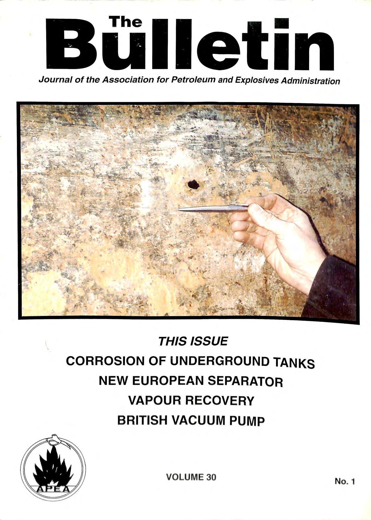
\ THIS ISSUE CORROSION OF UNDERGROUND TANKS NEW EUROPEAN SEPARATOR VAPOUR RECOVERY BRITISH VACUUM PUMP VOLUM E 30 No . 1
Journal of the Association for Petroleum and Explosives Administration
3000/L f ib erg la ss
P pin g is li ste d with Underwriters' Laborato rie s for use in und erfu el-handling syste m s. It ga s h l so b ee n tested a nd acce pt e d rJ ft e London Fire a nd Civil e ence Authority.
Thhi s m ea ns yo u h ave the ass uran ce t at o u r produ ct h as b een te s ted under the mo s t st rin ge nt cond it ions a nd is rated for press ures and t_e mp erat u res far in excess of J e gu lar pe trol s tation requirements.
You ca n in sta ll a Du a loy system in a bout o n e h a lf the time requ i red to pu; rn s tee l. In fact, yo u can taper th e e nd of o u r pip e 111 less t im e than it takes JU St to put a s tee l pipe in a p i p e V JSe
Bu t h ere's th e best part: you' ll prob a bl y find the inst alled cos t of a Du a loy sys t e m to be less th an fo r stee l-as it requires no sulphate resisting co ncrete surround.
Ameron h as a Dualo y system for every und e r gro u.nd fu e l-h an dlin g n ee d: w h et h e r 1t s conventional s in g le -wa ll piping or a co mpl e t e se con d a r y co ntainm e nt system.
For more information, write Ameron Fiberglass Pipe Division, lA Christchurch Road, Ashford Kent, TN23 lXB or call us on 0233 613884
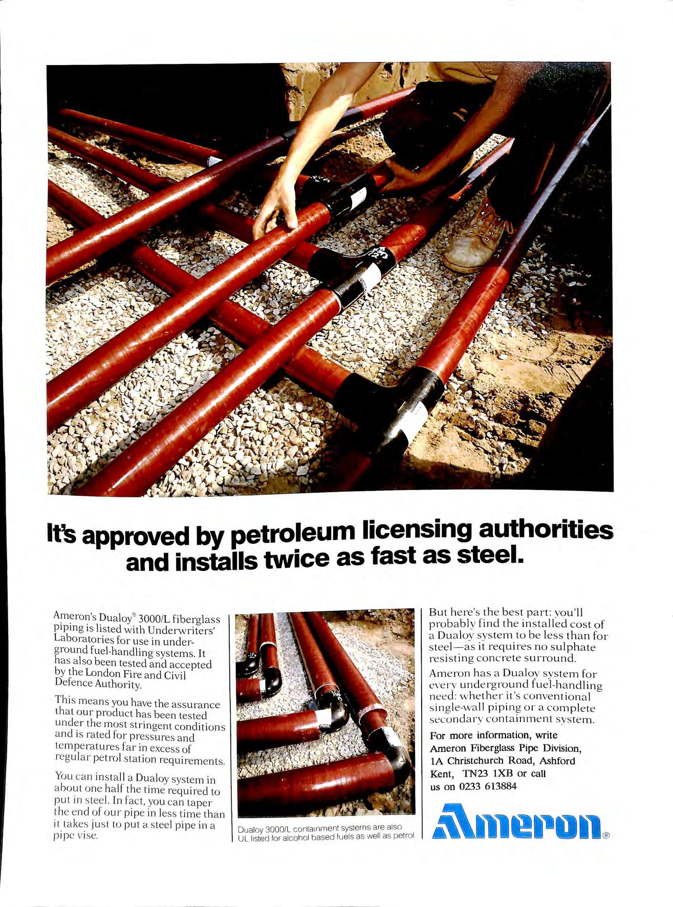
It's approved by petroleum licensing authorities and installs twice as fast as steel.
Dualoy 3000/l conta1nmen1 system s are also UL listed for alcohol based fuels as wel l as petrol
Major oil companies are investing large sums to control hydrocarbon emissions during fuel transfer. Vapours which up until now, have escaped into the atmosphere.
OPW Fueling Components are proud to have played a leading role in this development, by supplying the special valves and know-how, gained from I0 years experience of similar development in the U.S.A.
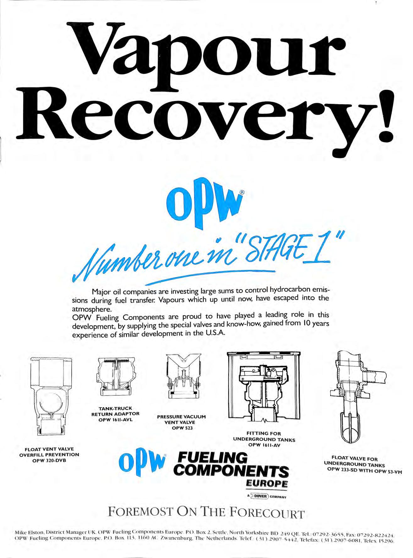
FLOAT VENT VALVE OVERFILL PREVENTION OPW 320 DVB TANK-TRUCK RETURN ADAPTOR OPW 1611-AVL PRESSURE VACUUM VENT VALVE OPW 523 FITTING FOR UNDERGROUND TANKS OPW 1611-AV 'oP\V FUEi.iNG COMPONENTS FLOAT VALVE FOR UNDERGROUND TANKS OPW 233 SD WITH OPW 53 VM EUROPE A oovi!) COMPANv FOREMOST ON THE FORECOURT Mi k e El st o n , D i str i ct Ma n ager UK. O PW Fu elin g Co m pone n ts Eu rop e P () _ Box 2 Se ttle , No rth Yo r ks hi re BD < , "' _ _ OPW Fu e l m g Co mp o n e n ts t u rope P O Box 11 -,, _ 11 60 AC Z.wane n b urg , T h e Ne th erl ands_'H:lef. (-,, 1 ) 2 < !el ::-0 7 292 Fax : 0 7 292-8 2 2424_ · ">'1'12 , l e l tfax : 0 1) 290 7 -608 1 Telex 1'>296 _
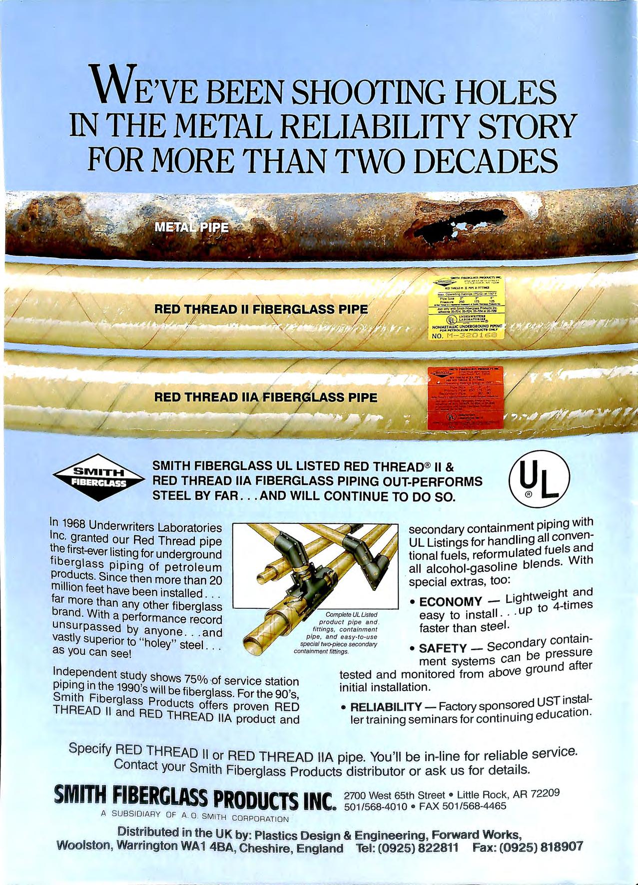
WE'VE BEEN SHOOTING ·HOLES IN THE METAL RELIABILITY STORY FOR MORE THAN TWO DECADES SMITH FIBERGLASS UL LISTED RED THREAD® 11 & RED THREAD llA FIBERGLASS PIPING OUT-PERFORMS STEEL BY FAR AND WILL CONTINUE TO DO SO. In 1968 Underwriters Laboratories Inc wanted our Red Thread pipe first-ever listing for underground fiberglass piping of petroleum pr??ucts Since then more than 20 feet have been installed b more than any other fiberglass · · gwith secondary containment pipin UL Listings for handling all convend tional fuels , reforr:iulated all alcohol-gasoline blen · · special extras, too: htweight and • ECONOMY LIQ to 4-times CompleteULUsted easy tO install· · 'UP product pipe and t el fittings, containment faster than s e . pipe, an d easy-to-use d ry containrand. With a performance record unsurpassed by anyone and vastly superior to " holey" steel as you can see! · · · specia/ two-piece secondary • SAF ETY _ secon a contammentf1ttmgs be pressure ment systems can und after Independent stud h . Y s ows 75% of service station 1990's will be fiberg lass For the 90 's, TH Products offe rs proven RED an ED THREAD llA product and tested and monitored from above gro initial installation • RELIA B ILITY Factory UST ler training semina rs for continuing educa Specify RED THREAD II or RED THREAD llA pipe. You'll be in-line for reliable service. Contact your Smith Fiberglass Products dist ributor or ask us for deta ils SM ITH FIBERGLASS PRODUCTS INC 2700 West 65t h Street• Little Rock , AR 72209 • 50 1/568-40 10 •FAX 50 1/568- 4465 A SUBSIDIARY OF A O SMITH CORPORATION Distributed in the UK by: Plastics Design & Engineering, Forward Works, Woolston, Warrington WA1 4BA, Cheshire, England Tel: (0925) 822811 Fax: (0925} 818907
JAMES LuKE & ASSOCIATES Safety & Training Consultants to the Petroleum Retail Industry SALUKI HOUSE 4 BURNT COMMON CLOSE RIPLEY, SURREY GU23 6HH Tel: 0483 222946 Fax: 0483 211328 Jobn -igfull & FIRST HANGINGS BLABYROAD ENDERBY LEICESTER LE9 SAQ Telephone (0533) 862287 Fora Comprehensive service for liquid fuel & LPG installations Consu/Jancy, design, installation, maintenance & decommissioning Gas..,free certificates Site surveys LPG vessel 5 & 10 year inspections MEMBER APEA, LPGITA TUBEFLOW LTD SPECIALISTS IN PETROL PUMP, TANK AND PIPEWORK INSTALLATIONS AND ASSOCIATED WORKS APPROVED CONTRACTORS TO THE PETROLEUM INDUSTRY AND LOCAL GOVERNMENT AUTHORITIES 29 TEMPLE STREET LONDON E2 6QQ Tel: 071-739 9538 Fax: 071-729 6108 MEMBER A.P.E.A. D D C BUILDERS LTD FOR SERVICE QUALITY & RELIABILITY WE OFFER A COMPLETE SERVICE ON MAINTENANCE AND IMPROVEMENT WORKS TO THE PETROLEUM RETAIL MARKET D DC BUILDERS LTD 7 ST CLAIR CLOSE CLAYHALL ILFORD ESSEX IG5 OPA Tel: 081=550 5216 Fax: 081 =55() 6095
The Storage Tank Specialists Established since 1857 "'ENVIROTANK " • Single and double skin petrol and diesel tanks • Above ground double skinned and bunded tanks • Galvanised tanks • Rectangular tanks • Cylindrical tanks • Site erected tanks JOSEPH ASH STORAGE TANKS Storage tanks for all purposes Tel: 021 622 4661 P.0.BOX 16, CHARLES HENRY ST., BIRMINGHAM 812 OSP Telex: 337978 GALTAN, Fax No: 021 622 1402 0
A. J. Bayliss (Stourport) Ltd Petroleum Engineers Petrol, Fuel Oil and Electrical Installations 3 MOORHALL DRIVE, STOURPORT-ON-SEVERN DV13 BSG TELEPHONE: 02993 4541-2-3 FAX: 0299 827638 SPECIALISING IN ALL ASPECTS OF FORECOURT PETROLEUM INSTALLATIONS AND SERVICING WELDEM CHESHIRE STREET, MOSSLEY, ASHTON-U-LYNE, LANCASHIRE, OL5 9NG MANUFACTURERS OF QUALITY STEEL STORAGE TANKS FOR THE PETROLEUM AND CHEMICAL INDUSTRIES UNDERGROUND SINGLE AND DOUBLE SKINNED ABOVE GROUND • OPEN OR SECURITY SELF BUNDED DIPSTICKS • GAUGES • LEAK DETECTION • OVERFILL PREVENTION FULL RANGE 500 GALLONS TO 40000 GALLONS PRICE LISTS AVAILABLE · SPECIALS ON REQUEST GENERAL FABRICATIONS· VESSELS· STEELWORK LARGE PIPEWORK TEL: 0457 833211 FAX: 0457 833185
NATIONWIDE TANK CLEANING SERVICE Petrol, oil and solvent tanks cleaned to associated petroleum industry standards. TEL: (0489) 783462 INDUSTRIAL CLEANING Factory clearances, decontamination of buildings and removal of laboratory chemicals. NATIONWIDE FORECOURT DRAINAGE AND INTERCEPTOR SERVICE The regular removal of silt and debris from drain-lines, gullies, interceptors and catch-pits, helps to keep your garage safe from fire and forecourt flood. TEL: (0386) 47190 TEL: (0452) 507432 BULK WASTE SERVICES Wide range of containers for dry industrial waste. Static compactors installed and serviced. TRADE EFFLUENT AND SPECIAL WASTE TREATMENT AND DISPOSAL 24 HOUR EMERGENCY HOTLINE SCHEME ALSO: SKIPS INDUSTRIAL CLEANING _GULLY CLEANING WATER JETTING CESSPIT EMPTYING CLEANSING SERVICE GROUP LTD Head Office: Grange Road, Southampton, Hants. S03 2GD TEL: BOTLEY (0489) 782232/6 FAX: 0489 789821

MANGAN BROS. LTD. Building Contractors 402 ·Seven Sisters Road, London N4 2LU (REGISTERED OFFICE) Telephone: 071 800 46 5 1 Specialists in Petrol Filling Stations
.. ED WARDS (Tank Cleaning) Ltd THE COMPLETE FUEL TANK SPECIALIST PETROL · OIL · CHEMICAL · STORAGE TANKS ABOVE OR BELOW GROUND CLEANED·GASFREED·REMOVED Cold cutting specialists Garage demolition Difficult location heating tanks removed Fuel tank inspection Non-destructive testing Written reports Slurry filling Gas free certification Fuel uplifting, using specialist pumping equipment All work to strict petroleum and HSE legislation *EXPERT ADVICE GIVEN FREE= APEA MEMBER * EDWARDS (Tank Cleaning) LTD CHURCH STREET9 CROYDON9 SURREY9 CRO lRF 0816869775 0816801890
u ILL POINT ADAPTORS D HEAR VALVES l!J ISPENSING NOZZLES I}) REAK AWAY COUPLINGS PETROLEUM SERVICE STATION EQUIPMENT SPECIALIST l!jAPOUR BALANCING RF ILL PREVENTION BSERVATION WELLS u OTAL CONTAINMENT MD 0 108 863931 Im 0708 868226 ·
Talking Point
Environmental Surveys being caiTied out for major oil companies have been causing problems for petroleum licensing authorities. Some so called "experts" have been using dangerous equipment while sites remain open and in one case a tank has been punctured and in others lines have been hit. It is clear that companies carrying out such surveys must first contact the petroleum authority and have a method statement aoreed on safe workmg practise and use safe equipment. It will also benefit the Oil Companies to ensure that these surveying companies employ competant persons familiar with the Safety problems on forecourts.
It is with sadness that the Association reports the death of Fred Wilson in Notes & News. Fred will be remembered by many of us in the Association for his humour, kindness and for the wealth of knowledge and experience he was willing to share with us in the APEA.
For members of the British Standard Committee on petrol pumps on which Fred was chairman the sign &indicating the non hazardous area will always be known as the "WILSON" Line.
I The Bulletin Published by the Association for Petroleum and Explosives Administration VOLUME, 30 Number l FEBRUARY 1992 A company Limited by Guarantee registered in England No. 2261660 Reg. Office: Stoughton House, Harborough Road, Oadby, Leicester LE2 4LP £5.00 (Free to Members) ISSN 0263 4597 Contents TALKING POINT NOTES & NEWS 2 CORROSION IN PETROL STORAGE TANKS 7 EUROPEAN STANDARDS ON INTERCEPTORS 10 VAPOUR RECOVERY MADAM VAPOUR PUMP HUMBERSIDE BRANCH J · Horsburah EASTERN BRANCH R. G. Green Protection Dept., 15 20 SOUTHERN BRANCH J. Luke MIDLAND BRANCH Mr. L. Lloyd CMS Ltd.
Journal
Opinions expressed in this
are not necessarily the views of the Association
ADVERTISING SECRET AIRY
Secretary: Mr D. Bucknall
Editor: Mr. J. A. J. Thompson.
MEMBERSHIP SECRET ARY B. J. Thompson
J. Luke Honorary
Honorary
OBITUARY FRED WILSON
We are sad to announce the untimely death of F. E. J. Wilson on Tuesday 28th January 1992 Fred Wilson will be known to many through his forty seven years spent in the Petroleum Industry. He spent thirty six years employed by A very Hardoll working through the ranks to become Chief Engineer, retiring in 1980. His latter years with A very Hardoll were spent mostly on behalf of the Petrol Pump industry , both in the UK as Chairman of the PPMA Technical Committee and in Europe representing the UK on CECO D.
Retirement to Fred Wilson still involved three or four day s a week in London or Paris representing the UK pump industry on numerous committees concerned with safety and metrology on the forecourt. He ret a ined the Chairmanship of the PPMA Technical Committee until his death. He was Chairman of the British Standard PCL/6 Committee which led to the publication of the BS 71 17 se rie s of standards for petrol pumps Fred Wilson's energy , technical knowledge , wide industry experience and boundle ss enthusiasm re s ulted in his repre se ntation on the HSE Committee responsible for the publication of HS(G)41, repre se nting the UK and OIML and on various other technical groups both in the UK and Europe.
will be sadly missed, and we pa ss on our sympathy to hi s widow Cath , who to his clo se friends and colleagues, is almo s t as well known as Fred.
BEW ARE DANGEROUS IMPORTS!
Reports have been received that leak detection equipment on double skin tanks has been installed which is not certified for use in hazardous areas. Some 100 in stallations in the UK are affected , mainly in the Midlands. Industry and local authorities should ensure that the leak detection control equipment supplied with the tanks is fully certified to Cenelec Standards and marked EEX( I).
The tank manufacturer concerned purchased equipment from Europe which is normally used with oil storacre tanks "' not containing flammable liquids
PROTECTIVE MULTIPLE EARTHING BANNED BY HSE
The Health & Safety Executive in a letter to petroleum licensing authorities have stated that the elecuical supply to petrol filling stations s hould not be by means of a sys tem in which the neutral and protective conductors are combined (ie. a TN-C-S system) or protecti ve multiple earthing (PME).
The fact that PME was banned on new sites led the HSE to review the dangers on existing sites and their advice was that
1. A maximum of 3 years should be a llowed for the complete removal.
2. In the inte rim period the current flowin g d ow n to forecourt equipment mu s t be measured and recorded
3. Where other works are carried out or future development may take place th e Licensing Authority m ay extend the period to co incid e with these changes.
THE PETROLEUM OFFICER'S GUIDE TO THE VEEDER-ROOT TLS-200R AUTOMATIC TANK GAUGE
To promote a better under sta nding of how th e Veeder Root TLS-200R Auto1:iatic Tank _Gauge works and hO\v it can b e use d 111 the UK toreco urt with respect to HS(G)41. V ee d e r Root have produc ed a s m a ll booklet aimed at tli e 1 ' t e eva nt li ce ns 111g authont1es.
Thi s guide de sc rib es the fea tur es of our o·lLer • 1 1 · . . "'' t" e anc ex p am s ho w a P et 1ol e um Ott1c e r v 1s 1t 1n o a . t · • · " < s 1 e can obtain 111tormat1on fr om th e syste m
Copies of thi s manual ha ve b ee n circLil ·lt · d t· 1 . , e o t 1e ma111 1I ce n s 111g authoriti es rn th e UK t1 Ltt 1 ·tl . .. u1 1e 1 copi e s can be ob ta111ed by P e t1ol e urn Ofhc e i·s 01 ot lle t· 1 1 Ill e t estec part 1es b y co nta c trng:-
Da v id Ersk in e or Ly nn H ood a t Veede r Root Limit e d. Kil s prnd1 e Road. Dund ee. DD2 3Q J Tel: 0.\8 2 8 :BO.\.\. Fa x: 0 \82 832.\82
notes
and news
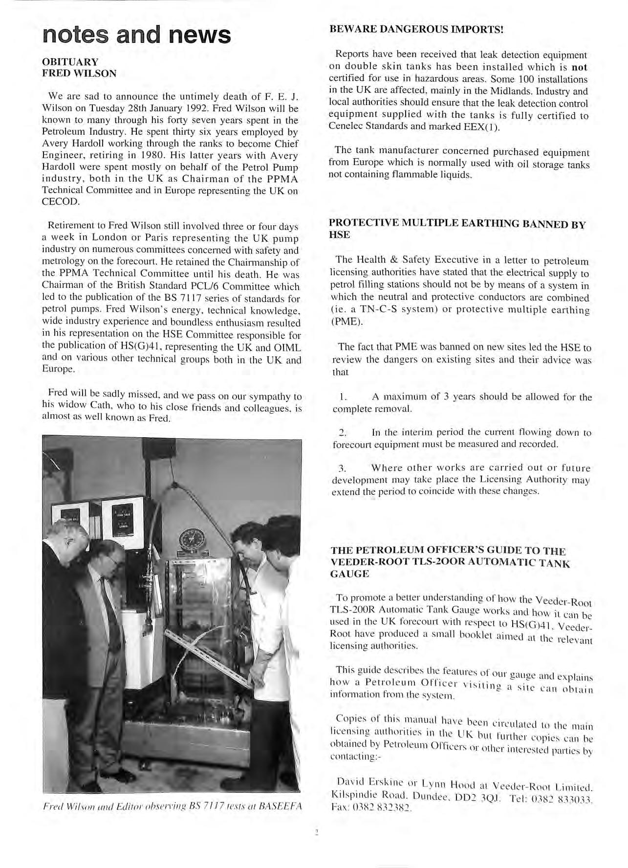
Fr ed Wil so n and Edito r 11hs e /"\"i11 g BS 7 11 7 tes ts 01 BASEEFA
FLEXIBLE PIPE WORK FAILURE IN USA
A Bufflex flexible pipe work system at a one year old service station in the USA suddenly failed spilling 4000 gallons of diesel fuel. The cause of the problem was determined to be the compatibility between the fuel and the primary pipe material. Bufflex had not been aware of a specification change by the manufacturer and had consequently installed the incon-ect material. Leak detection sensors were not wired up to shut off the pump therefor the loss was high, and a site clean up is being undertaken. Buffalo Environmental Products have stated that they have taken steps to prevent an occun-ence of this incident. There have been no installations of Bufflex in the UK to date.
MICRELEC INTRODUCE NEW SOFTWARE TO MEET HS(G)41 WET STOCK RECONCILIATION REQUIREMENTS
Developments to the MASTER SERIES software will enable MICRELEC customers to comply with the wet stock reconciliation requirement, to produce a daily record, which shows clearly all gains and losses for each tank.
The new software, which can be installed into any existing MICRELEC DAT APOS point-of-sale terminal, automatically processes volume sales data from the RECAL pump controller, and tank content levels (either via electronic tank gauge readings or manual tank dip entries) to provide dip loss reports for each tank and grade. This mformation is produced at the end of each shift and then compiled to give total figures for a given period. Simple graphs of these results (printed by the MASTER SERIES) enable unfavourable trends to be identified early.
The DAT APOS software has been additionally enhanced to service station managers with increased infonnation on fuel deliveries, fu11her aiding wet stock reconciliation.
For further info1mation please contact:
The Sales Department Micrelec PLC
Camphill Industrial Estate West Byfleet Surrey KT 14 6EW Tel: 0932 355255 Fax: 0932 353594
HOMES EVACUATED IN GULF TANKER OVERFILL
The London Fire Brigade prosecuted Mr Thambian Kunasekaram at Highgate Magistrates Court on 8 November I for to ascertain the contents of a petrol tank pnor to ?elivery into that tank, for authorising the delivery of 12.000 litres of petrol and allowing an overfill of petrol from that tank.
_During delivery in the early hours of the morning the hose connection started spraying petrol onto the wall and petrol flowed across the forecourt from the pumps.
The Brigade were called and a number of houses were e\ acuated close to the site.
Due lo pre-;surisation of the system some 60 gallons of pel rol had lo he pumped from the tank into a drum to prevent further outflow.
lhe defendant pleaded guilty and was fined £ 150 with £269 l mh. <I total 1Jf 1::419
LONDON PROSECUTES FOLLOWING FIRE AND EXPLOSION
Pothe Hille & Co Ltd were prosecuted for four offences of breach of condition of a petroleum spirit licence. The prosecution arose out of an explosion and _fire at Company's licensed wax-refinery factory premises at Mill River Wharf, Hunts Lane, E.15, on 15th August 1990.
The case came before Stratford (Newham East) Magistrates' Court on l 9th September I 99 I the Justices, on hearing the facts of the case. dechned jurisdiction. The apparent, though not reason may have been that they felt that their powers we1e limited the maximum fine in the Magistrates' Cou11 being , £8,000.
The matter was committed to the Crown Court and heard at Snaresbrook on Friday, 6th December.
Two of the offences charged failure to maintain bulk-head lamps, the vapour-proof protective lenses having been left off the lamps. The petroleum inspector thought these unprotected lights had been the cause of ignition but the Company alleged that the lights had not been connected at the time. To prove beyond reasonable doubt that the lights were live prior to the incident would have been difficult because as the petroleum inspector observed, most of the evidence was consumed by the fire and he could not help much on this point. Hence, these two offences were "left on the file" and the Defendant entered pleas of guilty to the remaining two offences, one involving the presence of smoking material including lighter fuel adjacent to vessel containing petroleum spirit and the other involvmg_ the careless leakage of petroleum spirit vapour. the cover of the vessel having been left off.
Since the incident, the Defendants had closed down the factory and moved their undertaking, they claimed. to Germany. Having heard the evidence, the Judge said that he would deal with the matter as if guilty pleas had been entered in the Magistrates' Court. He considered that the offences, although isolated and out-of-character, were potentially life-endangering and serious. This was reflected by a fine of £250 for offence (3) relating to a half-full can of cigarette lighter fuel, and £500 for offence (4) relating to the man lid of the extractor vessel being left off, and awarded the Authority its costs in full, i.e. £1,500, all payable within 28 days.
BUFFLEX
PROPOSED HEALTH AND SAFETY (FEES) REGULATIONS 1992. FEES FOR LICENSING OF STORES AND REGISTRATION OF PREMISES FOR THE KEEPING OF EXPLOSIVES ITEM Store licence Renewal of a store licence Registration of premises and renewal registration PREVIOUS FEE £55.00 £55.00 £9.50 NEW FEE £56.50 £56.50 £10.00 As with last year's 'Fees' Regulations, this year·s will include a provision to delay the introduction of the new fees to allow local authorities sufficient time to prepare their renewals for collection.
PETROL SPILL ALERT AT BP GARAGE
A full-scale emergency operation was launched on 17 October after a petrol spill at a Leicester garage.
Gallons of fuel seeped onto the forecourt of the St James Service Station, Leicester, dming a delivery.
And fireman praised the quick actions of a tanker driver, who they say may have averted a major incident.
The alann was raised at about 6.30pm when fuel began to bubble back from a storage unit as petrol was being pumped from an 8,000 gallon BP tanker.
In a massive operation, four pumps , a chemical unit with support pump, emergency tender and foam salvage tender were sent to the scene.
A nearby home was evacuated and the main Hinckley Road closed for a time.
About 30 firemen were needed to tackle the incident.
But within minutes the potentially serious situation was under control. Officers blanketed the pool of petrol with foam and secured the leak
They then washed the fuel away into an interceptor.
A city council pollution control officer was called out to the scene. But it is believed that no fuel has seeped into the sewerage system.
The man in charge of the operation, Station Officer Paul Reynolds, said the incident could have been much worse.
"Luckily the tanker driver followed the safety procedure to the and called us within seconds of suspecting that somethmg was wrong," he said .
"The garage staff were also very efficient in dealing with the incident and we were helped by the strong winds which dispersed a lot of the fumes.
A spokeswoman for the garage estimated she had lost around £2,000 in business.
A new Northern Branch of the Association has been formed. The first meeting took place on 28 November 1991 at the Novotel in Newcastle-upon-Tyne.
The meeting was attended by more than twenty members including various members from the region plus Brian Taylor, David Bucknall and Jim Luke from the APEA Council.
The arrangements for the meeting were made by Susan Brians, who recently became a member of the Association after taking part in the 1991 exhibition and seminar in Dunstable, and Roger Musgrave of Cleveland Fire Brigade, who is a member of the national Council of the Association.
The meeting was opened by Brian Taylor, the National Chairman, who expressed his delight at the formation of the branch and continued by giving a short presentation on developments in the field of c1ment technology, particularly with regard to environmental protection aspects , as it affects both local authority and industry members alike. His talk included an interesting display of overhead projections.
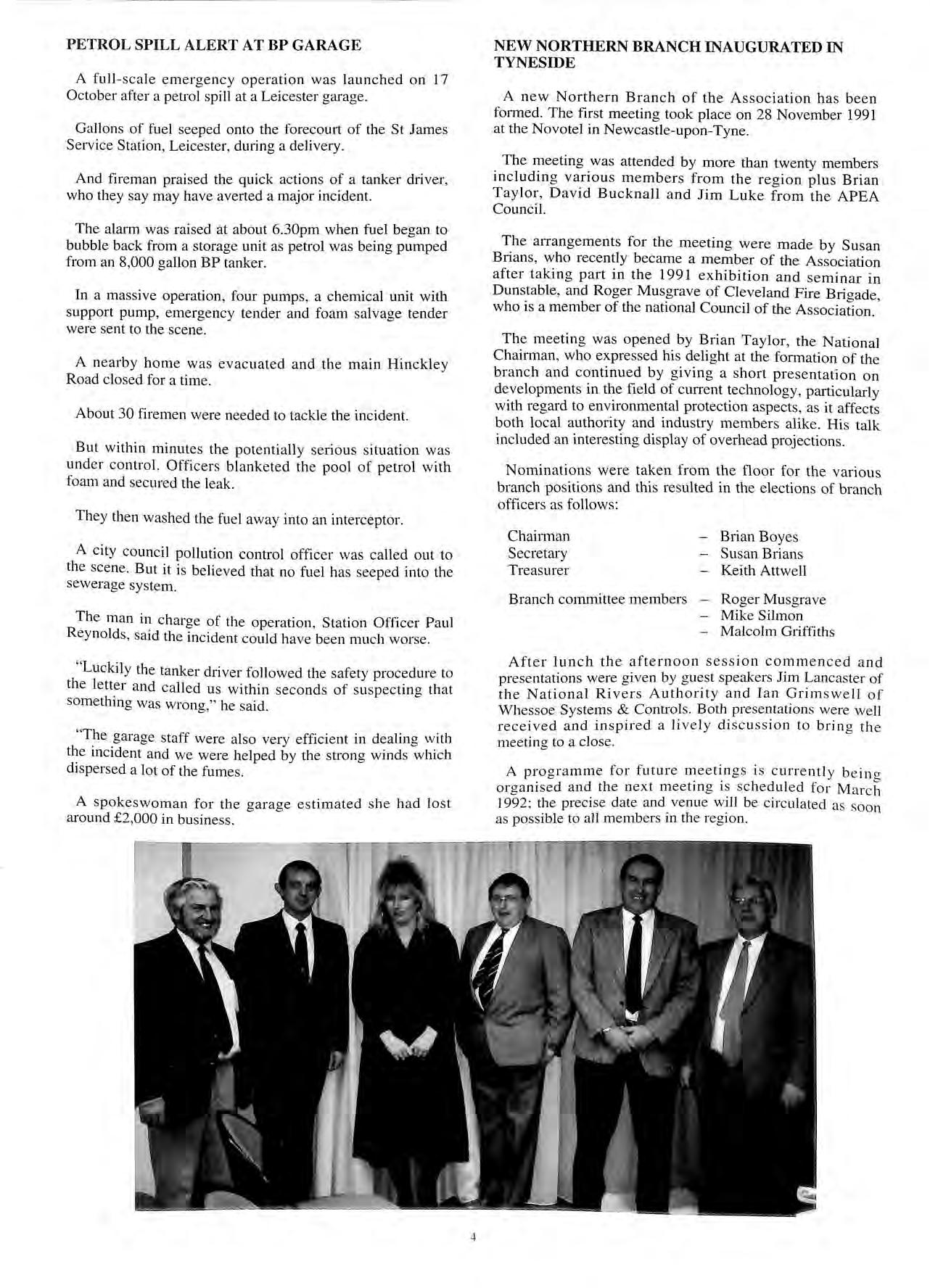
Nominations were taken from the floor for the various branch positions and this resulted in the elections of branch officers as follows:
Chairman Secretary Treasurer Branch committee members
Brian Boyes
Susan Brians
Keith Attwell
Roger Mu sgrave
Mike Silmon
Malcolm Griffiths
After lunch the afternoon session commenced and presentations were given by guest speakers Jim Lancaster of the National Rivers Authority and Ian Grimswell of Whessoe Systems & Control s. Both presentation s were well received and inspired a lively discussion to bring the meeting to a close.
A programme for future m ee tings i s currently beino organised and the next meeting is scheduled for Marc h J992 ; the preci se date and venue will be circulated as soo n as possible to all members in the region.
4
INAUGURATED IN
NEW NORTHERN BRANCH
TYNESIDE
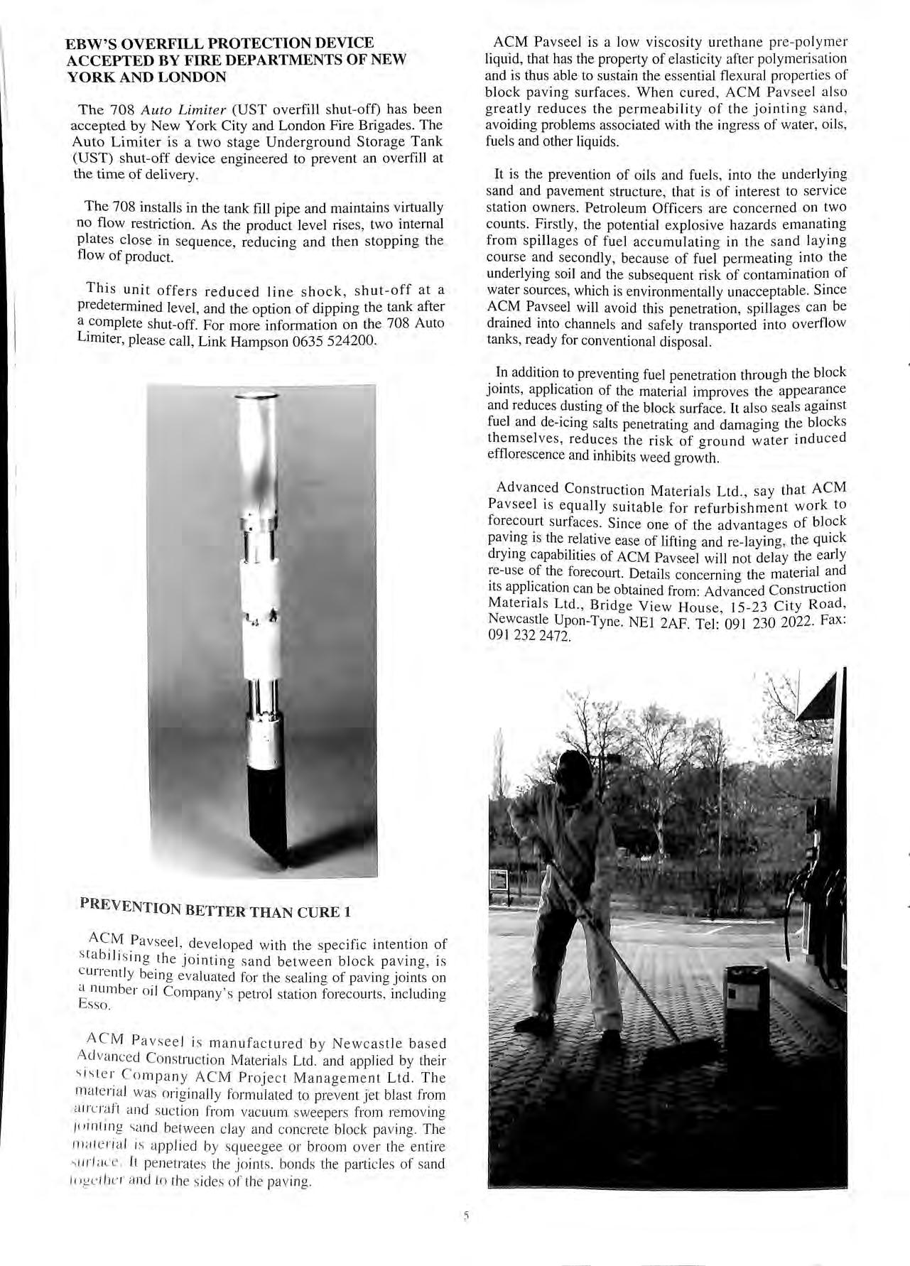
EBW'S OVERFILL PROTECTION DEVICE
ACCEPTED BY FIRE DEPARTMENTS OF NEW YORK AND LONDON
The 708 Auto Limiter (UST overfill shut-off) has been accepted by New York City and London Fire Brigades. The Auto Limiter is a two stage Underground Storage Tank (UST) shut-off device engineered to prevent an overfill at the time of delivery.
The 708 installs in the tank fill pipe and maintains virtually no flow restriction. As the product level rises, two internal plates close in sequence, reducing and then stopping the flow of product.
This unit offers reduced line shock, shut-off at a predetermined level, and the option of dipping the tank after a complete shut-off. For more information on the 708 Auto Limiter, please call, Link Hampson 0635 524200.
ACM Pavseel is a low viscosity urethane pre-polym e r liquid, that has the property of elasticity after polymeri s ation and is thus able to sustain the essential flexural prop e rties of block paving surfaces. When cured, ACM Pav s eel al s o greatly reduces the permeability of the jointing s and , avoiding problems associated with the ingress of water, oils , fuels and other liquids.
It is the prevention of oils and fuels, into the underlying sand and pavement structure, that is of interest to service station owners. Petroleum Officers are concerned on two counts. Firstly, the potential explosive hazards emanating from spillages of fuel accumulating in the sand laying course and secondly, because of fuel permeating into the underlying soil and the subsequent risk of contamination of water sources, which is environmentally unacceptable. Since ACM Pavseel will avoid this penetration, spillages can be drained into channels and safely transported into overflow tanks, ready for conventional disposal.
In addition to preventing fuel penetration through the block joints, application of the material improves the appearance and reduces dusting of the block surface. It also seals against fuel and de-icing salts penetrating and damaging the blocks themselves, reduces the risk of ground water induced efflorescence and inhibits weed growth.
Advanced Construction Materials Ltd., say that ACM Pavseel is equally suitable for refurbishment work to forecourt surfaces. Since one of the advantages of block pav ing is the relative ease of lifting and re-laying, the quick drymg capabilities of ACM Pavseel will not delay the early re-use ?f forecourt. Details concerning the material its apphcat1on can be obtained from: Advanced Construction Materials Ltd. , Bridge View House, I 5-23 City Road , Newcastle Upon-Tyne. NE! 2AF . Tel: 091 230 2022 Fax : 0912322472.
PREVEN TION BETTER THAN CURE 1
stC M P a v s eel , _ dev e lop e d w ith the s pecific intention of a bili s 1n g the J0111t111 g s and bet w een block pa v rng, 1s c urre ntl y be in g ev alu a te d for th e sealin o of pavino J·oints on 1 b b b ' num e r o il Compan y 's pe trol station forecourt s, includin g Esso.
AC M P avsee l i s m a nufa c tured b y N ew c a s tle ba se d A d va nce d Co n stru c ti o n M a te ri a ls Ltd. and applied by their C o mpan y AC M Pr o je c t Management Ltd. Th e m a te nal wa s ori g inall y formulat e d to prevent jet bla st from air cra ft a nd s uc tion from vac uum swee pers from remo vin g / 0 1lll111 g s a nd be twee n c lay a nd c o nc re te blo c k pa vin g. Th e m a te r ia l is a ppli e d by s qu eegee o r bro o m o ve r th e e ntir e '> ll r (ac e It pe net rat e s th e j o in ts. bo nd s the pa11icl es of sa nd lo gc lhcr a nd to th e s id e s of the pav in g.
5
J.E. Ellis Surrey County Council
With current thinking moving towards "Total Containment" the following suggestion is made with a view to inviting comments from members.
Each tank chamber would be interconnected by 1OOmm UPVC drain through rodding pit into 8000 litre -3 chamber interceptor.
Should drainage be joined outside tank area each bend could have access via cover.
Advantages are:-
1. All manhole chambers would be kept drier.
2. Fill pipe threads would therefore be less liable to corrosion.
3. All caps and locks would be easily retrieved.
4. Chambers could be pressure hosed with water to interceptor for cleaning and removing floating spirit.
5. Tank numbers and labels kept clean and readily identifiable.
The main disadvantage appears to be the venting of the interceptor into the manhole chambers. Since these are classified as Zone "O" it must be preferable to the gathering of raw spirit in these chambers. This containment would cut down contamination of the ground surrounding the tank area and would restrict the build up over the years.
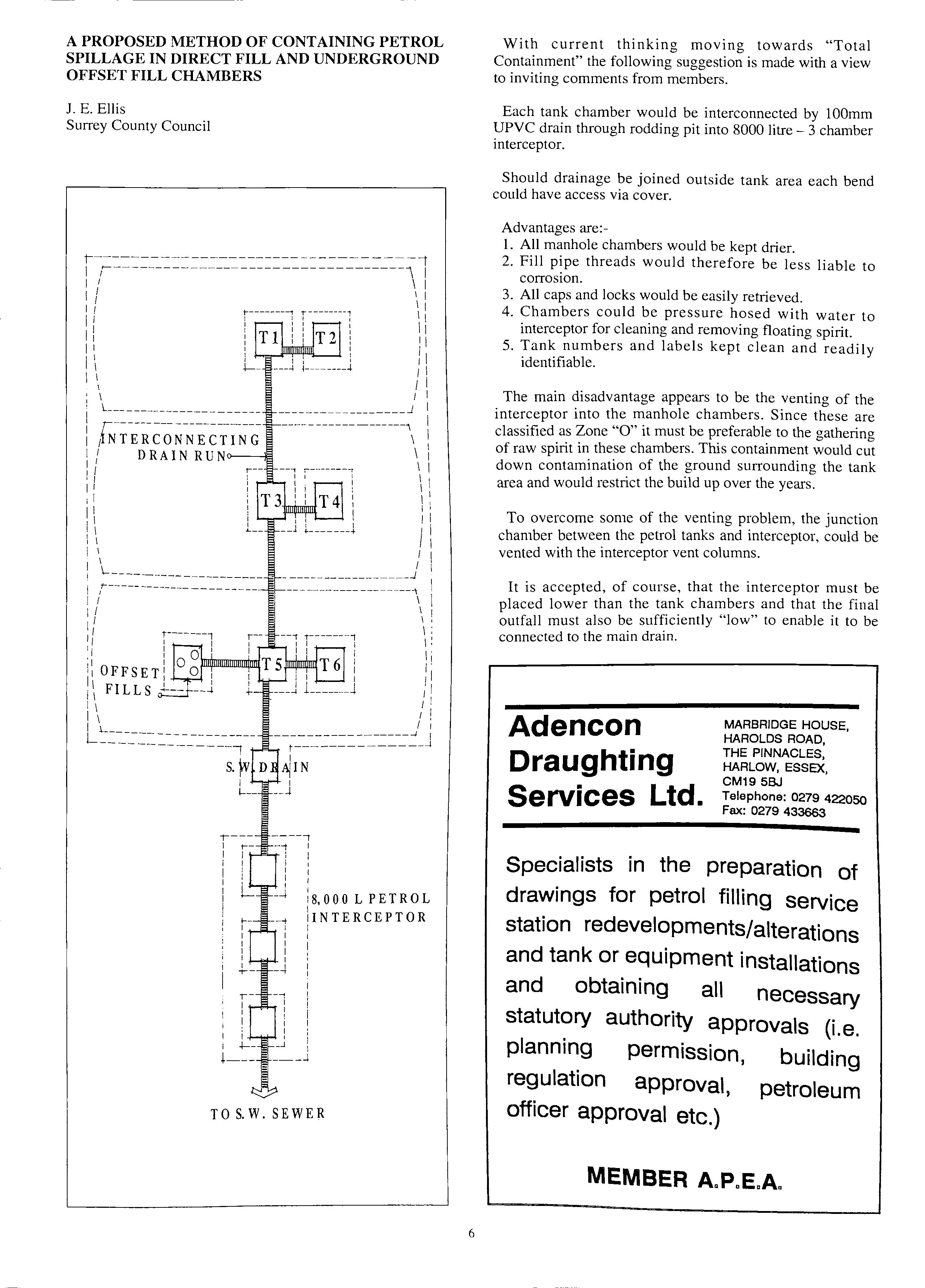
To overcome some of the venting problem, the junction chamber between the petrol tanks and interceptor, could be vented with the interceptor vent columns.
It is accepted, of course, that the interceptor must be placed lower than the tank chambers and that the final outfall must also be sufficiently "low" to enable it to be connected to the main drain.
A PROPOSED METHOD OF CONTAINING PETROL SPILLAGE IN DIRECT FILL AND UNDERGROUND OFFSET FILL CHAMBERS
;---1 I I I I I ----, --t I I I I I I I I I I I --l 18,000 L PETROL INTERCEPTOR I _..., I i i I I I I I _.J i ___ .J TO S. W. SEWER 6
Adencon Draughting Services Ltd. MARBRIDGE HOUSE, HAROLDS ROAD, THE PINNACLES, HARLOW, ESSEX, CM19 58.J Telephone: 0279 422050 Fax: 0279 433663 Specialists in the preparation of drawings for petrol filling service station redevelopments/alterations and tank or equipment installations and obtaining all necessary statutory authority approvals (i.e. planning permission, building regulation approval, petroleum officer approval etc.) MEMBER A.P.E.A.
CORROSION IN UNDERGROUND FUE L
STORAGE TANKS
By Norman Allen, Klargester Environmental Products Ltd.
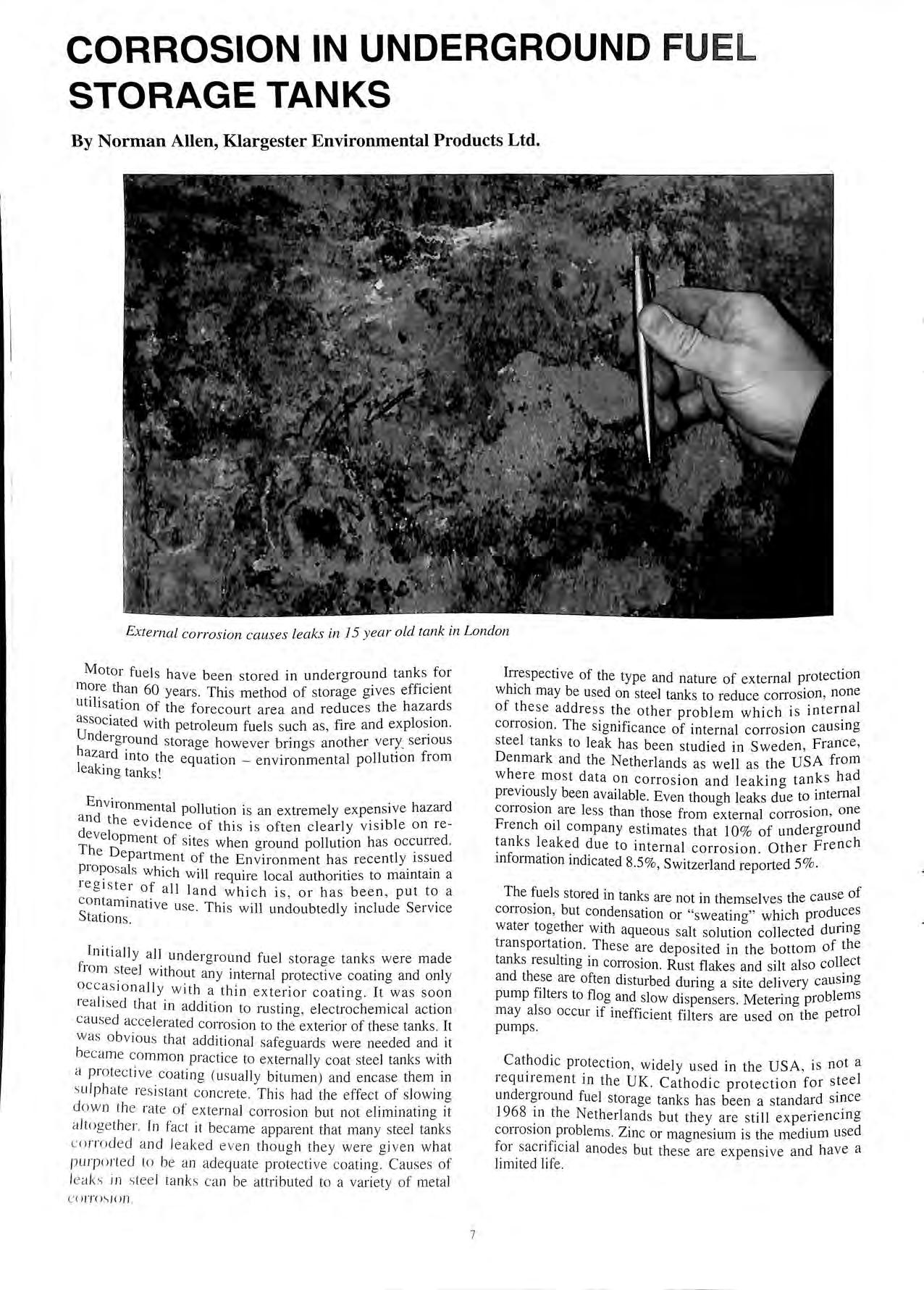
External corrosion causes leaks in J5 year old tank in London
Motor fuels have been stored in underaround tanks for b m?re than 60 years. This method of storage gives efficient utilisation of the forecourt area and reduces the hazards associated with petroleum fuels such as, fire and explos_ion. Underground storage however brings another very_senous hazard into the equation environmental pollution from leaking tank s 1
Environmental pollution is an extremely expensive hazard a nd the evidence of this i s often clearly visible on redevelopment of s ite s when ground pollution ha s occurred. The Department of the Environment has recently issued which will require local authorities to maintain a iegi s ter of all land which is or ha s been , put to a contaminative use. Thi s will undoubtedly include Service Stations.
Initially all underground fuel s torage tanks were made fr o m s teel without any internal protective coating and only occas ion a lly w ith a thin exterior coating . It was soon rea li se d that in addition to ru s ting , electrochemical action ca use d acce lerated corros ion to the exterior of these tanks It wa s obv iou s that a dditional safea uard s were needed and it bec ame com mon practice to coat steel tanks with a p ro tective coat ing ( us ually bitumen) and encase them in s ulph ate res is tant co nc rete. Thi s had th e effec t of s lowing down th e r ate o f ex ternal co rro sio n but not eliminating it a /t oget he r. In fa c t it became apparent that many stee l tanks c o rr ode d a nd lea ked eve n t h oug h they were given w hat p urp orted lo be a n adeq uat e protec tive coat ing. C ause s of le ak s in s tee l ta n ks ca n be attrib uted to a va ri e ty of me tal
Irrespective of the type and nature of external protection which may be used on steel tanks to reduce corrosion, none of these address the other problem which is inter?al corrosion. The significance of internal corrosion causmg steel tanks to leak has been studied in Sweden, France, Denmark and the Netherlands as well as the USA from where most data on corrosion and leaking tanks had previously been available. Even though leaks due to internal corrosion are less than those from external corrosion, one French oil company estimates that 10% of underground tanks leaked due to internal corrosion. Other French information indicated 8.5%, Switzerland reported 5%.
The fuels stored in tanks are not in themselves the cause of corrosion, but condensation or "sweating" which water together with aqueous salt solution collected dunng transportation. These are deposited in the bottom of the tanks resulting in corrosion. Rust flakes and silt also collect and the_se are often disturbed during a site delivery causing pump filters to flog and slow dispensers . Metering problems may also occur if inefficient filters are used on the petrol pumps.
Cathodic protection, widely u s ed in the USA, is not a requirement in the UK. Cathodic protection for steel underground fuel storage tanks has been a standard smce 1968 in the Netherlands but they are still experiencing corrosion problems. Zinc or magnesium is the medium used for sac rificial anodes but the se are expensive and ha ve a limit ed life
C O IT O S JOn 7
Sweden, where steel tanks have been required to be protected both internally and externally since 1970, report that up to 50% of leaking tanks were due to internal corrosion. Cast magnesium anodes have been used for internal protection in Sweden , but recent studies discovered that unleaded petrol containing methanol and isobutyl alcohol affected the anodes resulting in zinc anodes now being recommended. The other method used is to line the steel tank on at least the bottom one third with GRP. Of the two methods, Swedish authorities believe the GRP lining to be more effective and thi s is the more widely used method.
In Denmark the internal corrosion problem has been addressed by using sacrifical anodes, zinc coating or GRP lining. Tanks are inspected initially every 10 years as an important part of Environmental monitoring.
In the Netherlands where cathodic protection has been required since 1968, corrosion problems are still being reported. Annual inspections are now mandatory and removal of any water and sediments found takes place. Wall thicknesses are then measured. This is an important factor as a corrosion rate of only 0.35 millimetres per year could cause a 6.0 millimetre tank wall to fail in 17 years.
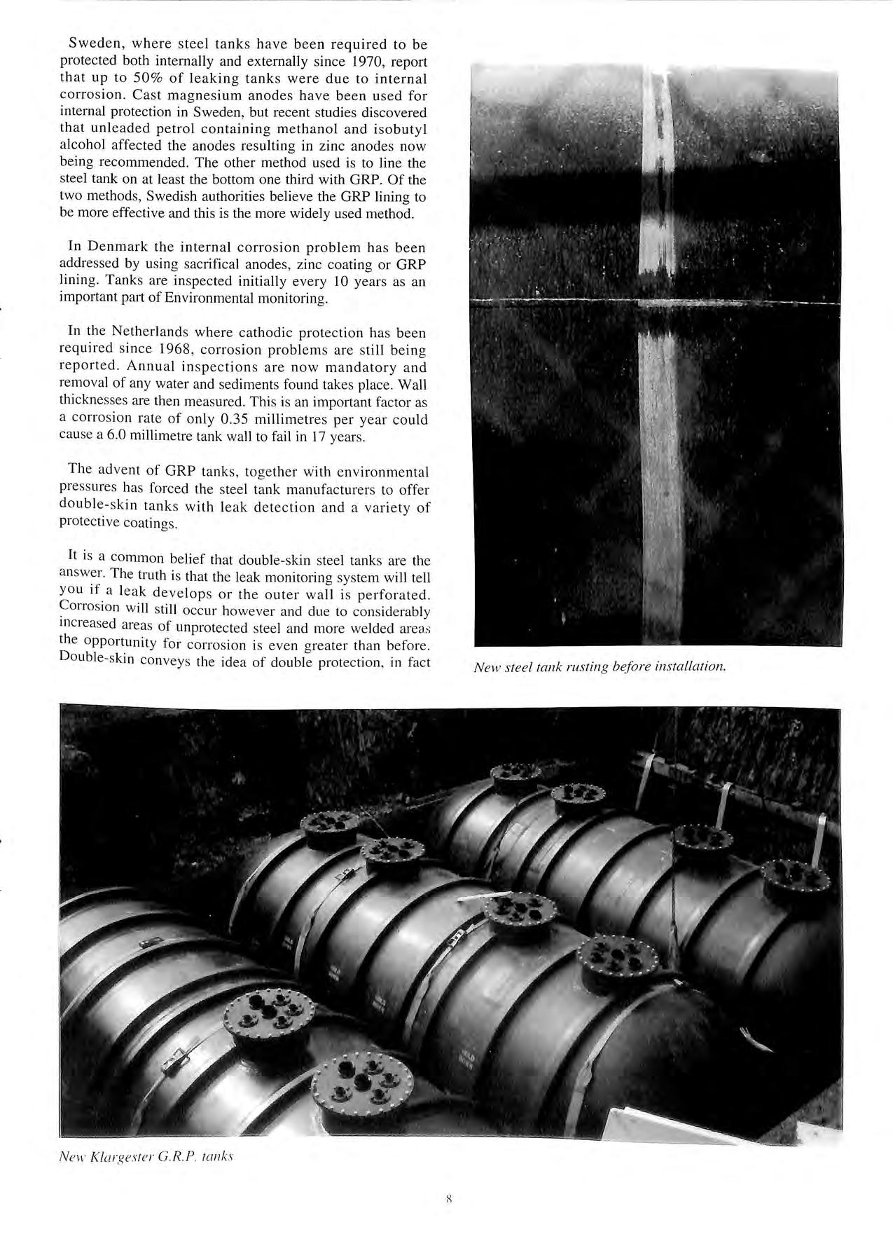
The advent of GRP tanks , together with environmental pressures has forced the steel tank manufacturers to offer double-skin tanks with leak detection and a variety of protective coatings.
It is a common belief that double-skin steel tanks are the answer. The truth is that the leak monitoring system will tell you if a leak develops or the outer wall is perforated. Corrosion will still occur however and due to considerably increased areas of unprotected steel and more welded area,; the opportunity for corrosion is even greater than before. Double-skin conveys the idea of double protection , in fact
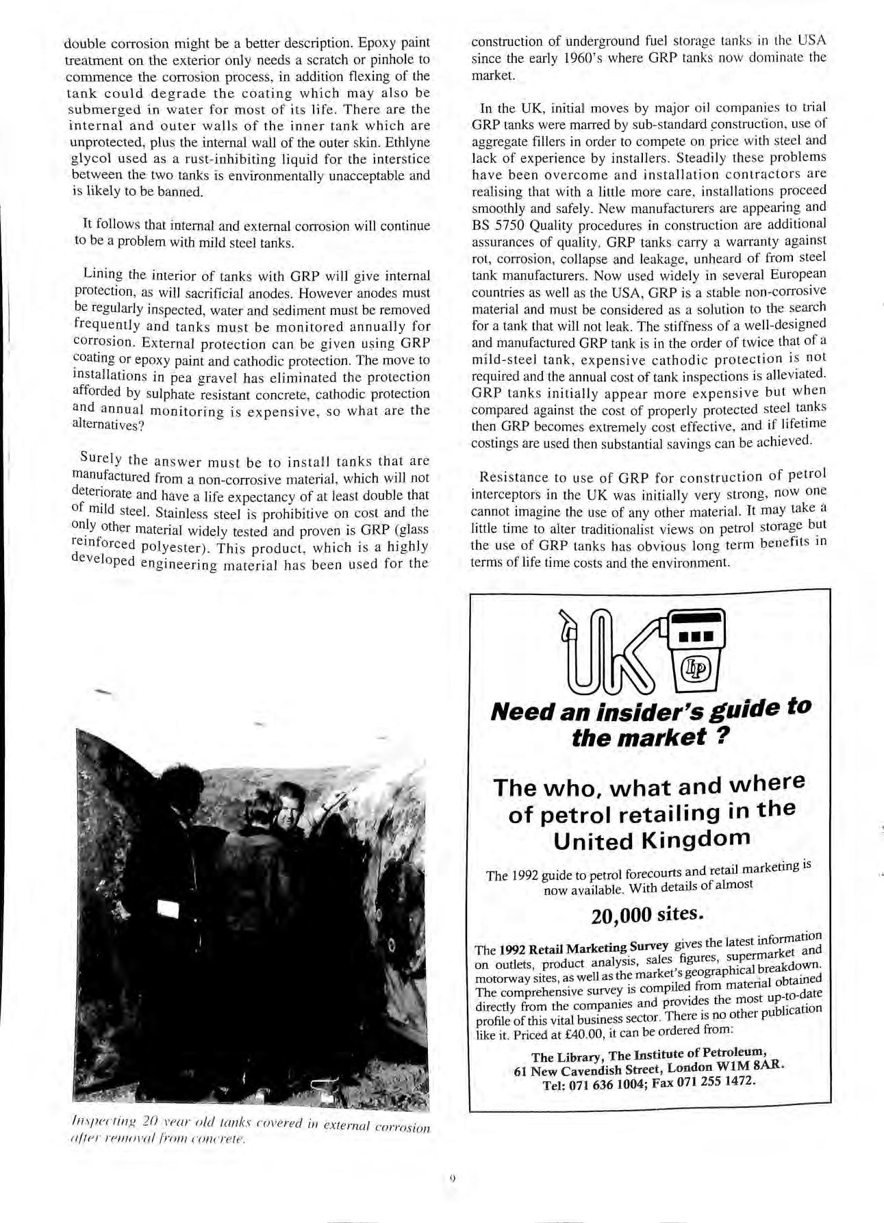
 N e M · K/ a rges re r G.R.P ra nk s
N ew steel tank rusting before in s tallation.
N e M · K/ a rges re r G.R.P ra nk s
N ew steel tank rusting before in s tallation.
double corrosion might be a bette r description. Epoxy paint treatm e nt on the exterior only n eed s a s cratch or pinhole to commence the corrosion proce ss , in addition flexing of the t a nk could degrade the coating which may also be s ubmerg e d in water for m os t of its life. There are th e internal and outer walls of the inner tank which are unprotected , plus the internal wall of the outer skin. Ethlyne g lycol used as a rust-inhibiting liquid for the inter s tice b e tween the two tanks is environmentally unacceptable and is likely to be banned.
It follows that internal and external corrosion will continue to b e a problem with mild s tee l ta nk s
Lining the interior of tank s with GRP will give internal protec ti o n , as will sacrificial a nod es. However anodes must be reg ularly inspected , water a nd se dim e nt must be removed frequently and tanks mu st be monitored annually for corrosion. External protection can be given using GRP coating or epoxy paint and cathodic protection. The move to m s tallations in pea gravel h as e liminated the protection afforde d by sulphate resi s ta nt concrete, cathodic protec tio n and an nual monitorin g is ex pen s i ve, so what are th e alterna ti ves ?
Surely the answer mu s t be t o in sta ll tanks that a re from a non- co rro sive material, which will not etenora te and have a life expectancy of at least double that of mild steel. Stainless steel is prohibitive on cost and the on.ly other material widely te s ted a nd proven is GRP (glass polyester) . This produ c t , which is a hi g hly eve l oped engineerin g material ha s been used for the
construction of und e rgro und fuel s tora ge tank s in the USA since the early l 960 ' s where GRP tanks now dominate th e market.
In the UK, initial move s by major oil companies to trial GRP ta nks were ma rred by sub- standard use of aggregate fillers in orde r to compete on pric e with stee l and lack of experience by in s tallers. Steadily the se probl e ms have been overcome a nd installation contractor s a re realising that with a little more care, install a tion s proceed smoothly and safely. New manufacturers are a ppe a ring and BS 5750 Quality procedures in construction are additional assurances of qu a lity GRP tank s carry a warranty against rot, corrosion, collapse a nd le a ka ge, unhea rd of from s tee l ta nk manufacturers. Now use d widely in several Europe a n countries as well as the USA, GRP is a stable non-corro sive material and must be considered as a solution to th e searc h for a tank that will not leak . The stiffness of a well de s igned and manufactured GRP tank is in the order of twice th a t of a mild-steel tank , expensive cathodic protection i s not required and the annual cost of tank inspections is alleviated. GRP tanks initi a lly ap p ea r more expensive but when compared again st the cost of properl y protecte d s tee l tanks th e n GRP becom es extremely cost effective , and if life time costings are used th e n s ub stantial savings can be achieved .
Re s istance to u se of GRP for construction of petrol interceptors in the UK was initially very strong, n ow one cannot imagine the use of any other material. It may ta ke a little time to alter traditi o na li st views on petrol s torage but the use of GRP t a nk s h as obvious long term b e n e fit s in terms of life time costs and the environment.
•••
Need an insider's guide to the market?
The who, what and where of petrol retailing in the United Kingdom
d il rketing is
The 1992 guide to petrol forecourts reta ma now available. With details of almost 20,000 sites.
th 1 t t informatio n
The 1992 Retail Marketing Survey gives e a es rket and on outlets product analysis, sales figures , shiupalermbaakdown ' . k t' geograp c re motorway sites as well as the mar e s · 1 bta ined ' · mpiled from maten a o The comprehensive survey is co u -to-date directly from the companies and provides the most blication profile of this vital business sector. There is no other pu like it. Priced at £40.00, it can be ordered from The Library, The Institute of Petroleum, 61 New Cavendish Street, London WIM SAR Tel: 071 636 1004; Fax 071 255 1472
! 11 1p e ('fi11 K 2 0 ve ar o ld la nk s c o ve red in ext e rnal corro · sion u /7e r r e mo vul j rom crm c re l e. 9
-
THE EUROPEAN EXPERIENCE
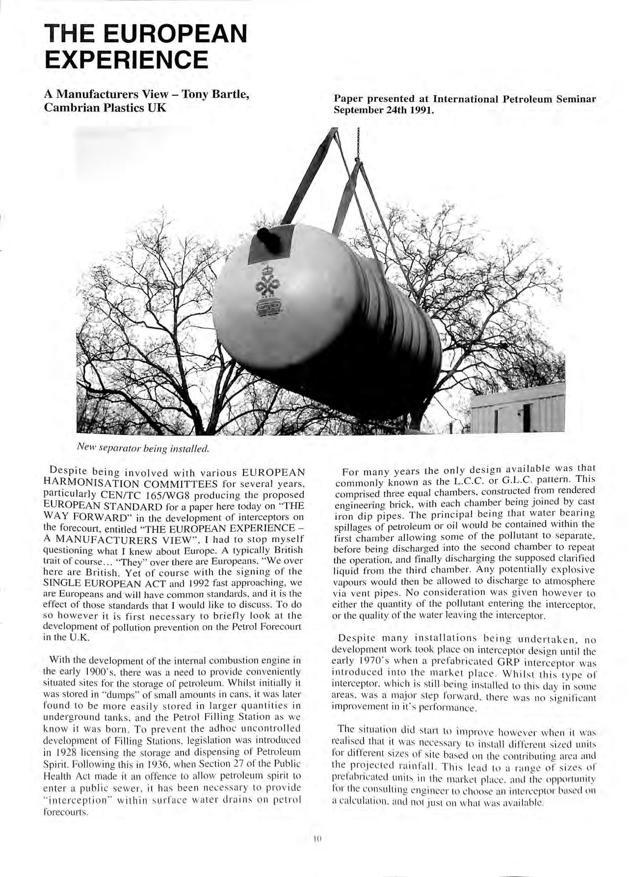
New separator being installed.
Despite being involved with various EUROPEAN HAJ_<MONISA TION COMMITTEES for several years, part1cularly CEN/TC 165/WGS producing the proposed EUROPEAN STANDARD for a paper here today on " THE WAY FORWARD" in the development of interceptors on the forecourt, entitled "THE EUROPEAN EXPERIENCE A MANUFACTURERS VIEW" , I had to stop myself questioning what I knew about Europe. A typically British trait of course "They" over there are Europeans , "We over here are British. Yet of course with the signing of the SINGLE EUROPEAN ACT and 1992 fast approaching, we are Europeans and will have common standards, and it is the effect of those standards that I would like to discuss. To do so however it is first necessary to briefly look at the development of pollution prevention on th e Petrol Forecourt in the U.K.
With the development of the internal combustion engine in the early 1900' s, there was a need to provide conveniently s ituated sites for the storage of petroleum. Whil st initially it was stored in " clumps " of small amounts in cans, it was lat e r found to be more easily s tored in larger quantitie s in underground tanks , and the Petrol Filling Station as we know it was born. To prev e nt the aclhoc uncontroll ed development of Filling Stations , leg is lation was introdu ced in 1928 licensing the sto rage and dispen s ing of Petroleum Spirit. Following thi s in 1936 , when Section 27 of the Public Health Act made it an offence to allow petroleum s pirit to e nter a public sewe r , it h as been n ecessa ry to provid e " int e rception " within s urfac e water drain s on petrol forecourts.
For many years the only design available was commonly known as the L.C.C. or G.L.C. pattern. This comprised three equal chambers , rendered enaineerina brick, with each chamber being 10111ed by cast dip pipes. The principal being that _water beming spillages of petroleum or oil would be contamecl w1th111 the first chamber allowing some of the pollut a nt to separate , before being clischa.rgecl into the second chamber to repeat the operation, and finaJly discharging the supposed clarified liquid from the third chamber. Any potentially explosive vapours would then be allowed to discharge to atmosphere via vent pipe s No consideration was given howev e r to either the quantity of the pollutant entering the interc e ptor, or the quality of the water leaving the interceptor.
Despit e many installations being undertaken, no development work took plac e on interceptor de s ign until the 1970 's when a prefabric a ted GRP interceptor was introduced rnto t.h e mark e t plac e . Whilst this typ e of mterceptor. which 1s s till b e ing install ed to this da y in some areas, was a forward, ther e \vas no s ignificant improv e me nt 111 It' s performanc e
Th e s ituati o n did s tart to improv e h oweve r when it was rea li sed that it was necessa r y to in s tall different si zed unit s lor d1Herent si z es of site based on the contributin<J a rea and the proj ec t ed r a infall. This lead to a r a ng e of s i z es of J?refa bri cate d unit s in th e mark e t place. and d1 e oppo rtunit y lor th e co ns ulting e ngin ee r to c hoo se an inte rceptor based o n a ca lculat1011 . and no t just on what was ava ilable.
A Manufacturers View - Tony Bartle, Cambrian Plastics UK
10
Paper presented at International Petroleum Seminar September 24th 1991.
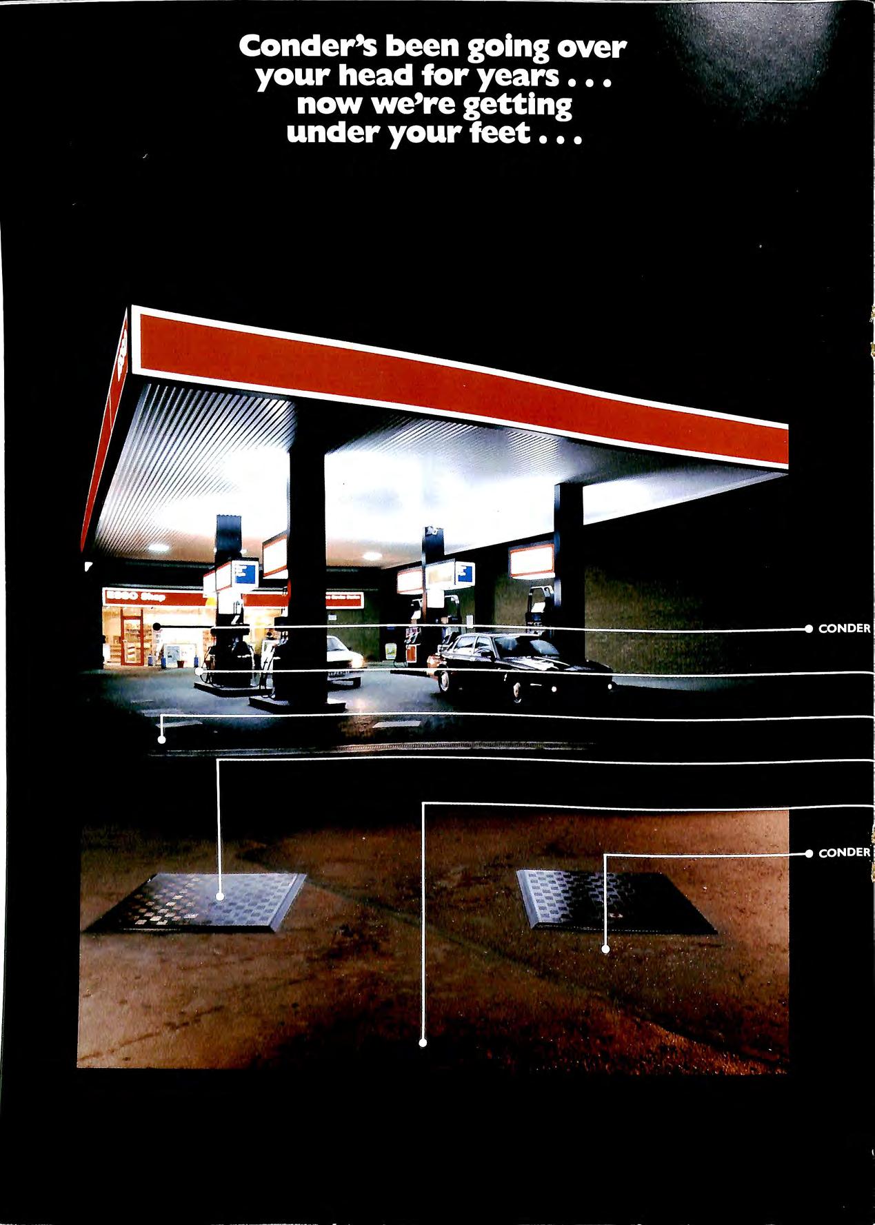
Conder's aim has always been to develop better products and building methods to accelerate the construction process the sooner your forecourt is up and running, the sooner your return on investment. 30 years ago we introduced the prefabricated Canopy, later the GRP Interceptor and most recently the revolutionary Fibrelite Access Covers with their light weight, you don't need a 'feat' of strength to lift them. Now, Conder can offer a complete range of ready made products designed specifically for the forecourt.
Modular Convenience Store and Car Wash buildings deli vered to site ready wired, plumbed and fitted out for rapid assembly; Access Chambers to contain possible fuel spillage and keep out sub-soil water; Silt Traps to avoid drain blockages and last, but not least, Pump Island Barriers all from one source and delivered to site.
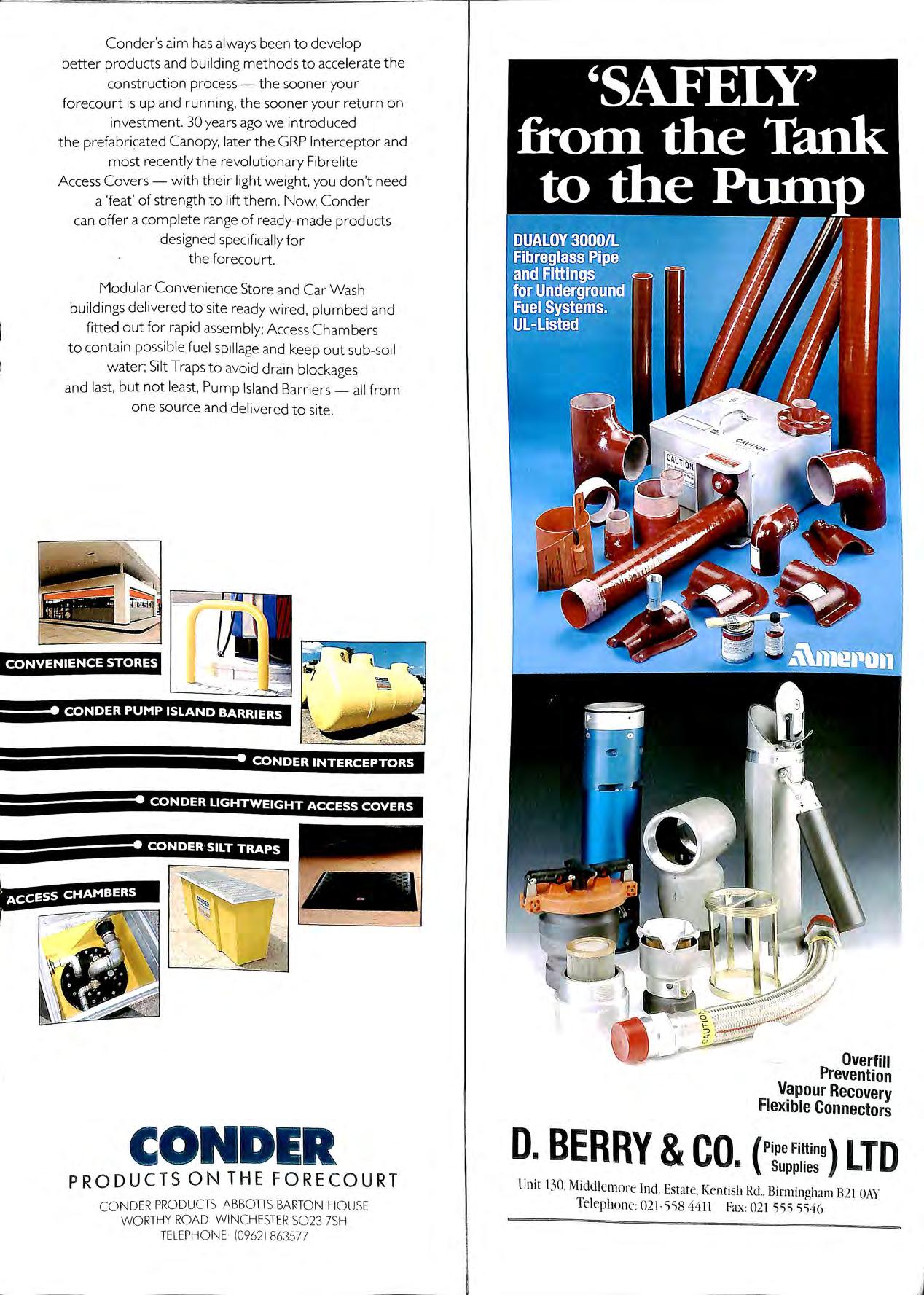
CONVENIENCE STORES CONDER PUMP ISLAND BARRIERS CONDER INTERCEPTORS CONDER LIGHTWEIGHT ACCESS COVERS CONDER SILT TRAPS CONDER PRODUCTS ON THE FORECOURT CO NDER PRODUCTS ABBOTIS BARTO N HO USE WO RTHY ROA D WINCHESTER 5023 7SH TE LEPH O NE (09621 863577 D. BERRY &CO. Overfill Prevention Vapour Recovery Flexible Connectors { Pipe I 'JO Supplies L Unit 130, Middlem ore Ind Estate. Kentish Rd. , Birmingham B21 OAY Telephon e: 021 5'i8 44 11 fa....: 021 'i55 55 46
Other developments were taking place, at the same time on the forecourt, which affected the type and size of interceptor which would be required. The advent of a specifically designed "pump island" covered by a canopy, offset fills , automatic car washes etc. were offering the consultant , designer , and the legislative authorities some new problems. Whilst it was obvious that the "old" type of interceptor was not satisfactory, very little was done other than to perhaps shorten the dip-pipes and call it a grit trap, to remove the dip-pipes and call it a grit trap , to remove the dip-pipes and call it an oil interceptor, put a bigger one in and call it a containment tank ... Nobody actually looked at the specific problems of the forecourt and designed an interceptor to overcome them.
It has therefore been some 70 years since the first 3 chamber oil interceptor was designed , and little has changed . We still have no National Standards , and with little or no legislation capable of demanding change there is unlikely to be any . This is very frustrating not only for the Licensing Authorities, but also for forward thinking, developing like my own. The market is full of so called mterceptors which are simply copies of existing products , made using inferior manufacturing methods and with no proof as to whether they do or do not work There are also many differing claims as to which separator is the correct one for the forecourt. The advent of the HSE Guidelines has made our job a little easier by asking for a minimum capacity in a separator of not less th a n one chamber of a tanker (effectively a minimum nett storage of 7500 litres). This is however still only a recommendation and some s uppliers and installers still insist on the cheapest
possible option and in s tall, if allowed to get a w ay w ith it, the original 1800 litre type three chamber unit wh e ther it is suitable or not.
It is however only 100 days until that magical date of the I st January 1992, and despite the fact that most of the new European Standards will not be ready by then , they are coming , and speaking as a manufacturer it will not be too soon!!! All of this type of product will then have to comply with some fairly rigorous standards, and I would suggest in the final analysis there will be some that will be found lacking.
Five of the most likely requirements to be included within the new standard, are that each type of unit will have to :
1 Be type tested by a third party to a standard far exceeding that which is currently acceptable in the U.K. It will be a two tier standard, units that are capable of producing effluent of a quality of not more than 5 milligrams per litre of oil for sensitive areas, and not more than 100 milligrams per litre for less sensitive areas (what type to be used to be decided by the consent to discharge).
2. To comply with a stringent in situ test to confirm it is capable of withstanding the loadings that it is likely to encounter under its normal working conditions i.e. tanker axle loadings , ground loadings and hydrostatic pressure.
3. Have a closure device on the outlet which is capable of preventing the discharge of pollutant, which has already been separated, should the unit not be maintained or more impo1tantly , should there be a major spillage.
i
Patent App i1o d for
4. Have adequate provision for the separation and storage of sediment.
5. Have an alarm to indicate that the separator needs emptying.
ALL OF THESE ARE REQUIREMENTS THAT SHOULD BE CONSIDERED WHEN DESIGNING, SPECIFYING OR INST ALLING A FORECOURT SEPARATOR
What are the problems faced by todays designers and legislators?
I. The containment of a major spillage of petroleum or oil if it should occur.
2 The collection and removal of every day accidental spillages of petroleum or oil.
3. The removal of excessive amounts of grit and sediment generated by todays very efficient lance and automatic car washes.
4. The requirement to reduce the amount of pollutants currently being discharged from so called efficient separators.
5. The need to provide equipment which can readily be maintained , but which, in the event of lack of maintenance, will not allow already removed pollutants to be discharged.
6. The need to comply with current UK statutory requirements and likely future European requirements.
Whether you represent a Licencing Authority, a Specifier, an Installer, an Oil Company Exec., or an end user, I hope I have provoked you into asking the question why these problems have not been addressed before? Why we/you continue to allow the installation of inferior products. Why a manufacturer has not gone out on his own and produced a unit that will satisfy the needs of the industry
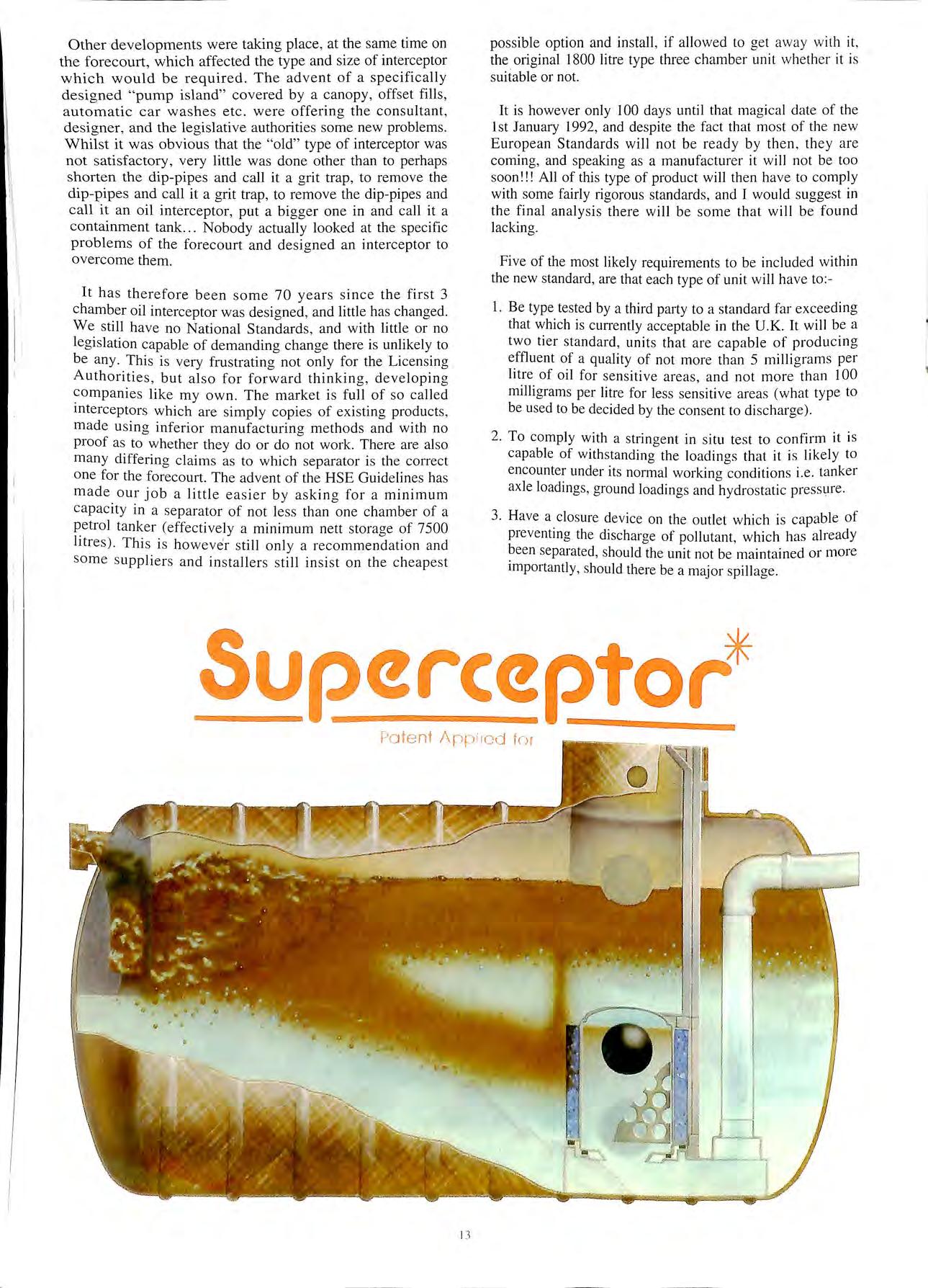
Well one manufacturer has this is the CAMPLAS SUPERCEPTOR, the only unit on the market today which addresses all of these problems.
The Superceptor is supplied with an automatic closure device , a coalescing filter which will meet the proposed European standard on discharge.
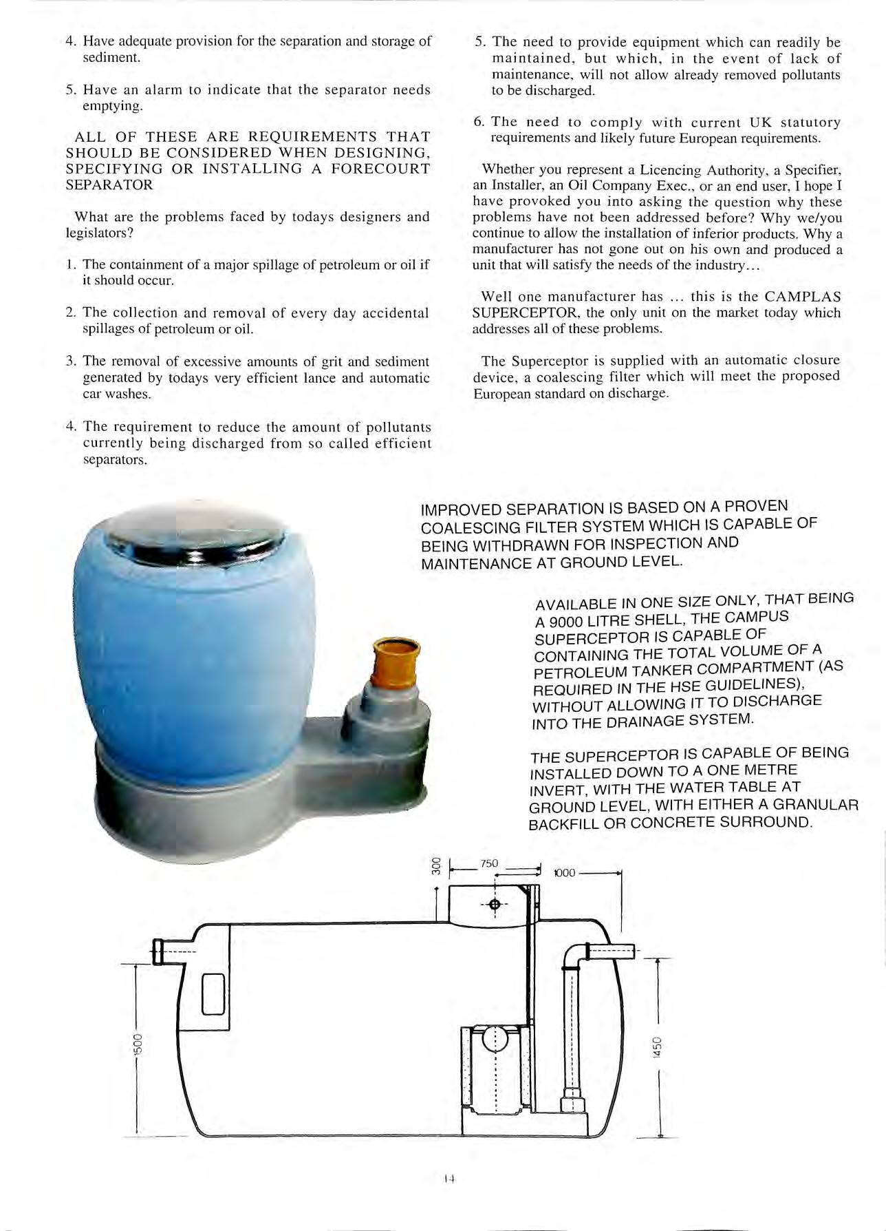
IMPROVED SEPARATION IS BASED ON A PROVEN COALESCING FILTER SYSTEM WHICH IS CAPABLE OF BEING WITHDRAWN FOR INSPECTION AND MAINTENANCE AT GROUND LEVEL.
AVAILABLE IN ONE SIZE ONLY, THAT BEING A 9000 LITRE SHELL, THE CAMPUS SUPERCEPTOR IS CAPABLE OF CONTAINING THE TOTAL VOLUME OF A PETROLEUM TANKER COMPARTMENT (AS REQUIRED IN THE HSE GUIDELINES), WITHOUT ALLOWING IT TO DISCHARGE INTO THE DRAINAGE SYSTEM.
THE SUPERCEPTOR IS CAPABLE OF BEING INSTALLED DOWN TO A ONE METRE INVERT, WITH THE WATER TABLE AT GROUND LEVEL, WITH EITHER A GRANULAR BACKFILL OR CONCRETE SURROUND.
0 0 0 14
Ul
T 0
s:
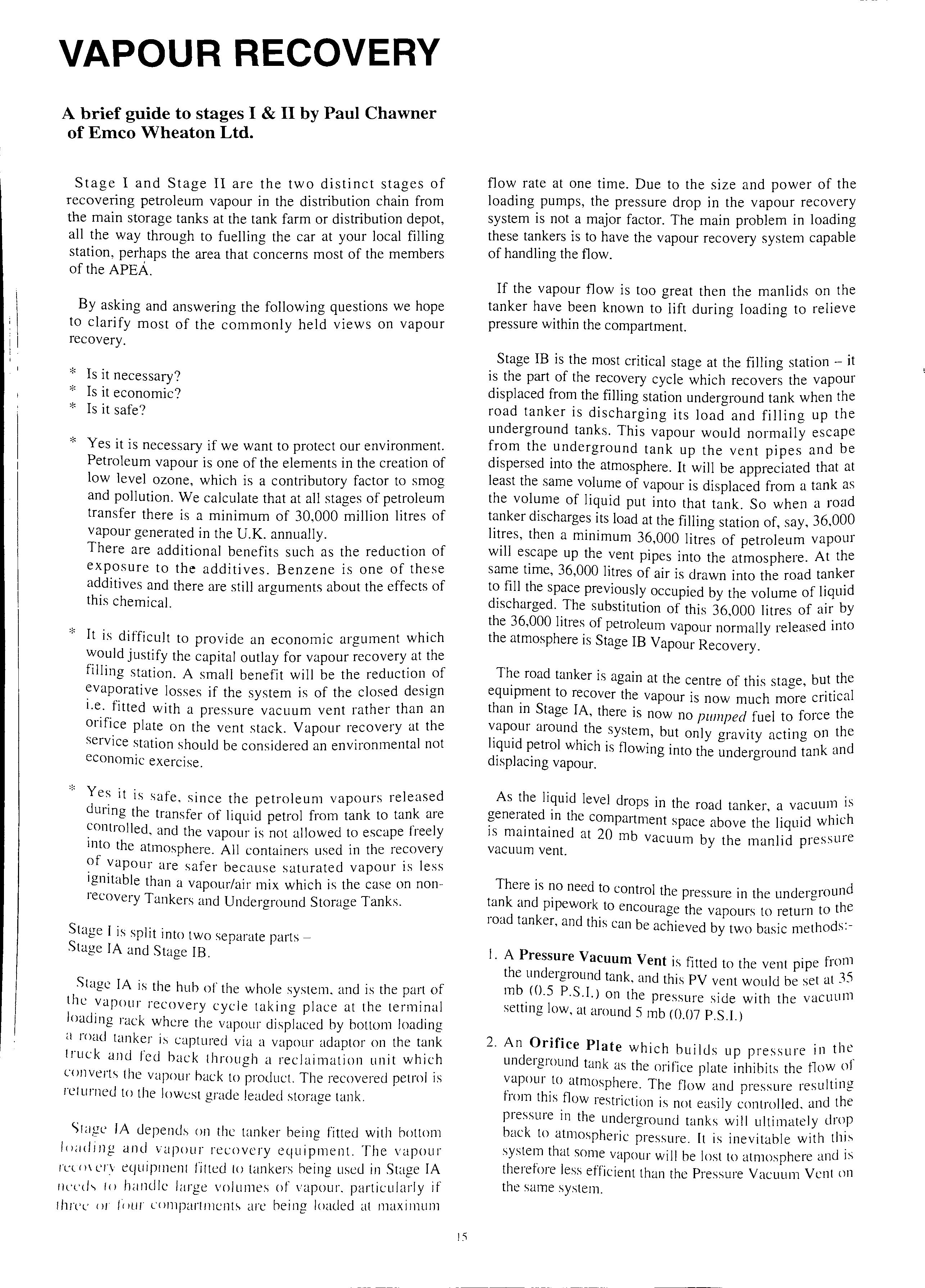
VAPOUR RECOVERY
A brief guide to stages I & II by Paul Chawner of Emco Wheaton Ltd.
Stage I and Stage II are the two distinct stages of recovering petroleum vapour in the distribution chain from the main storage tanks at the tank farm or distribution depot, all the way through to fuelling the car at your local filling station, perhaps the area that concerns most of the members of the APEA.
By asking and answering the following questions we hope to clarify most of the commonly held views on vapour recovery.
* Is it necessary?
* Is it economic?
* Is it safe?
* Yes it is necessary if we want to protect our environment.
Petroleum vapour is one of the elements in the creation of low level ozone, which is a contributory factor to smog and pollution. We calculate that at all stages of petroleum transfer there is a minimum of 30,000 million litres of vapour generated in the U.K. annually.
There are additional benefits such as the reduction of exposure to the additives. Benzene is one of these additives and there are still arguments about the effects of this chemical.
* It is difficult to provide an economic argument which would justify the capital outlay for vapour recovery at the filling station. A small benefit will be the reduction of evaporative losses if the system is of the closed design i.e. fitted with a pressure vacuum vent rather than an orifice plate on the vent stack. Vapour recovery at the service station should be considered an environmental not economic exercise.
* it is safe, since the petroleum vapours released durmg the transfer of liquid petrol from tank to tank are and the vapour is not allowed to escape freely mto the atmosphere. All containers used in the recovery of vapour are safer because saturated vapour is less ignitable than a vapour/air mix which is the case on nonrecovery Tankers and Underground Storage Tanks.
Stage 1 is split into two separate parts Stage IA and Stage IB.
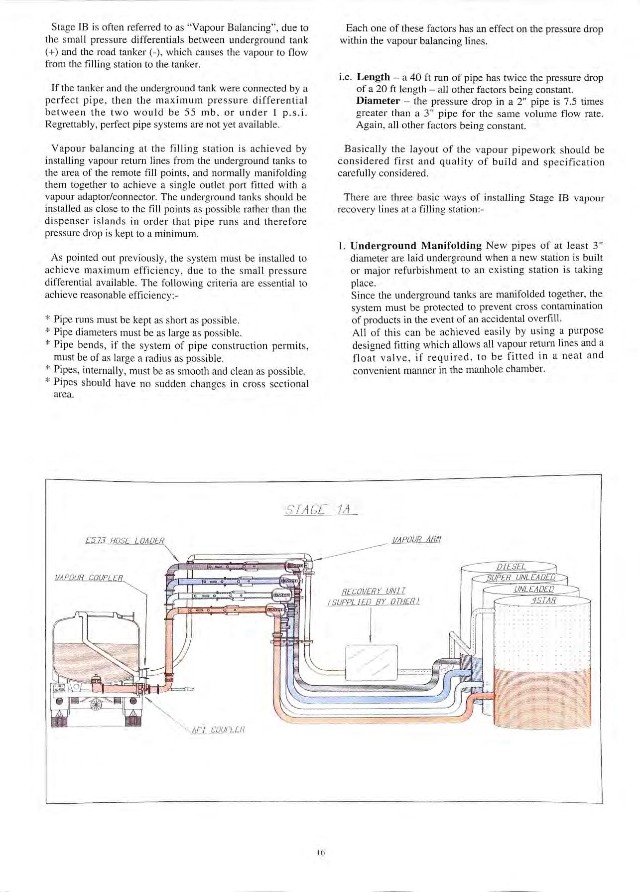
Stage IA is the hub of the whole system. and is the part of the :vapour recovery cycle taking place at the terminal loadmg rack where the vapour displaced by bottom loading a road tanker is captured via a vapour adaptor on the tank !ruck and fed hack through a reclaimation unit which converts the vapour hack to product. The recovered petrol is returned to the lowest grade leaded storage tank.
IA depends on the tanker being fitted with bottom loading <Jnd vapour recovery equipment. The vapour rn m erv equipment fitted to tankers being used in Stage IA llLTd-. lo handle large volumes of vapour. particularly if three or l'riur compartment!-. are being loaded at maximum
flow rate at one time. Due to the size and power of the loading pumps, the pressure drop in the vapour recovery system is not a major factor. The main problem in loading these tankers is to have the vapour recovery system capable of handling the flow.
If the vapour flow is too great then the manlids on the tanker have been known to lift during loading to relieve pressure within the compartment.
Stage IB is the most critical stage at the filling station it is the part of the recovery cycle which recovers the vapour displaced from the filling station underground tank when the road tanker is discharging its load and filling up the underground tanks. This vapour would normally escape from the underground tank up the vent pipes and be dispersed into the atmosphere. It will be appreciated that at least the same volume of vapour is displaced from a tank as the volume of liquid put into that tank. So when a road tanker discharges its load at the filling station of, say, 36,000 lit_res, then a minimum 36,000 litres of petroleum vapour will escape up the vent pipes into the atmosphere. At the same time, 36,000 litres of air is drawn into the road tanker fill the space previously occupied by the volume of liquid discharged. The substitution of this 36 OOO litres of air by the 36,000 litres of petroleum vapour released into the atmosphere is Stage IB Vapour Recovery.
road tanker is again at the centre of this stage, but the eqmpment to recover the vapour is now much more critical than in Stage IA, there is now no pumped fuel to force the around system, but only gravity acting on the hqmd petrol which is flowing into the underground tank and displacing vapour.
As the liquid level drops in the road tanker a vacuum is _in the compartment space above liquid which 1s mamtamed at 20 mb vacuum by the manlid pressure vacuum vent.
There is no need to control the pressure in the underground tank and pipework to encourage the vapours to return to the road tanker, and this can be achieved by two basic methods:-
!. A Pressure Vacuum Vent is fitted to the vent pipe from the underground tank, and this PY vent would be set at 35 mb (0.5 P.S.l.) on the pressure side with the vacuum setting low, at around 5 mb <0.07 P.S.I.)
2. An Orifice Plate which builds up pressure in the underground tank as the orifice plate inhibits the flow of :apour .to atmosphere. The flow and pressure resulting from this flow restriction is not easily controlled. and the pressure in the underground tanks will ultimately drop back to atmospheric pressure. It is inevitable with this system that some vapour will be lost to atmosphere and is therefore less efficient than the Pressure Vacuum Vent on the same system.
Stage IB is often refen-ed to as " Vapour Balancing" , due to the s mall press ure differentials between underground tank ( +) and the road tanker (- ), which cau ses the vapour to flow from the filling station to the tanker.
If the tanker and the underground tank were connected by a perfect pipe , then the maximum pre ss ure differential between the two would be 55 mb , or under I p.s.i. Regrettably , pe1fect pipe systems are not yet available.
Vapour balancing at the filling station is achieved by installing vapour return lin es from the underground tank s to the area of the remote fill points, and normally manifolding them together to achieve a single outlet port fitted with a vapour adaptor/connector. The underground tanks should be installed as close to the fill points as po ss ible rather than the dispenser i s lands in order that pipe run s and th e refore pre ss ure drop is kept to a minimum
As pointed out previously, the system mu st be in stalled to achieve maximum efficiency, due to the s mall pressure differential ava ilable The following criteria are essential to achieve rea so nable efficiency :
* Pipe runs must be kept as short as possible.
* Pipe diam eters must be as large as po ssi ble.
* Pipe bend s, if the sys te m of pipe construction p e rmit s, must be of as large a radiu s as po ss ible
* Pipe s, internally, must be as smooth and clean as po ssi ble.
* Pipes should have no s udden changes in cross sect ional area.
Each one of these factors has a n effect on the pressure drop within the vapour balancing lines.
i.e. Length a 40 ft run of pipe has twice the pressure drop o f a 20 ft length all other factors being constant. Diameter the pressure drop in a 2" pipe is 7.5 times grea ter than a 3" pipe for the same volume flow rate. Again, all other factors bein g constant.
Basically the l ayo ut of the vapour pipework should be considered fir s t an d quality of build and s pecification carefully considered .
Th e re are thr ee basic ways of installing Stage IB vapour recove ry lines at a filling station :
I. Underground Manifolding New pipes of at least 3" diameter are laid underground when a new station is built or major refurbi shment to an existing sta tion is taking pl ace.
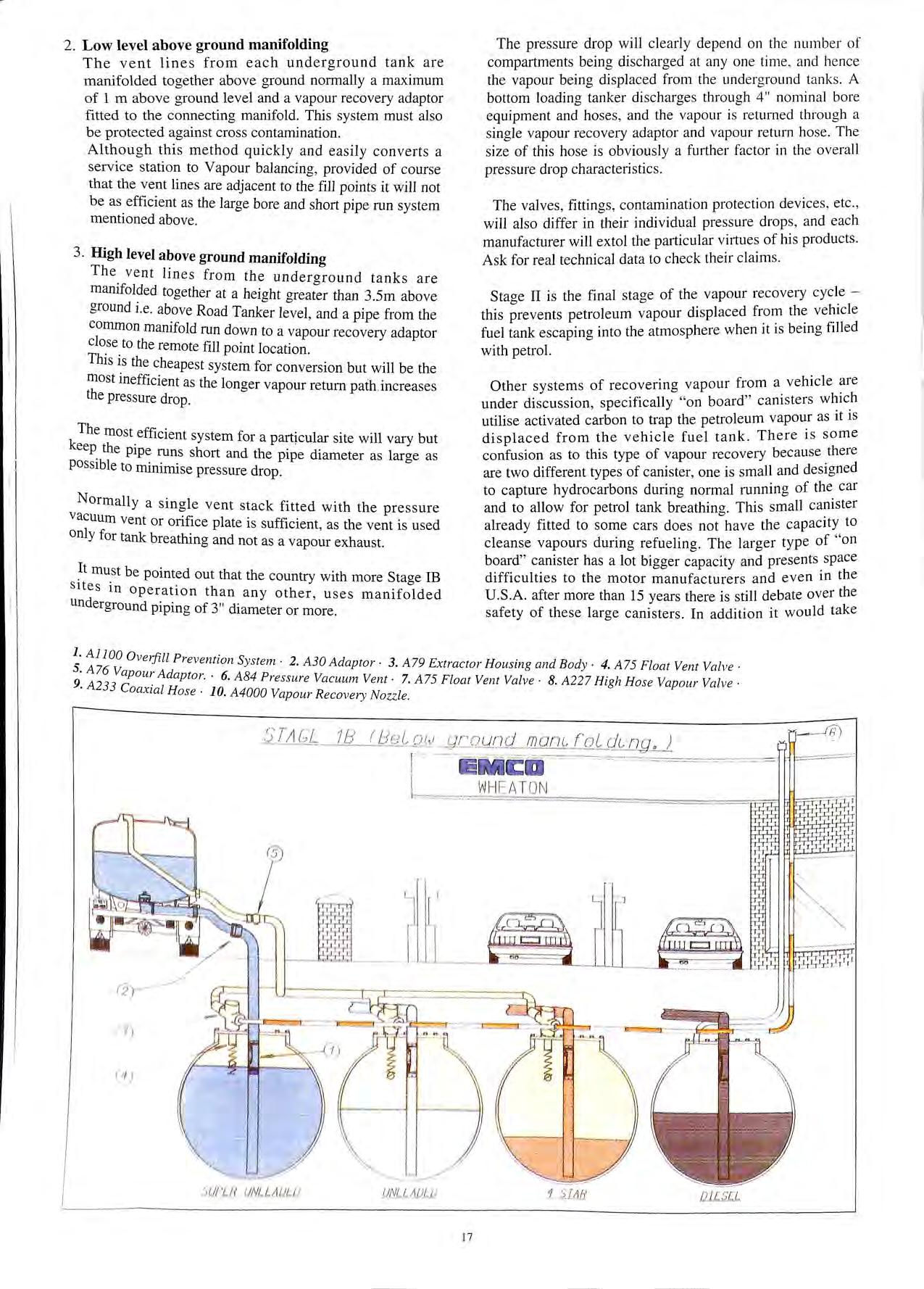
Since the underground tanks are manifolded together , th e s ystem mu st be protected to prevent cross contamination of products in the event of an accidental overfill. All of thi s can be achieved easily by u s ing a purpo se de sioned fittino which allows all vapour return lines and a "' "' float valve , if required , to be fitted in a neat and convenient manner in the m anhole chamber.
ST/JG £ 1/J
""'
VAPOUR AR/1 -----------0 oi:::;;31 Q 16 RECOVERY UN IT (5UPP L JED BY OTHER J
E573 NOSE L011DER
J!APOUR COUPL ER
2. Low level above ground manifolding
The vent lines from each underground tank are manifolded together above ground normally a maximum of 1 m above ground level and a vapour recovery adaptor fitted to the connecting manifold. This system must also be protected against cross contamination.
Although this method quickly and easily converts a service station to Vapour balancing, provided of course that the vent lines are adjacent to the fill points it will not be as efficient as the large bore and short pipe run system mentioned above.
3. High level above ground manifolding
The vent lines from the underaround tanks are manifolded together at a height than 3.5m above ground i.e. above Road Tanker level, and a pipe from the common manifold run down to a vapour recovery adaptor close to the remote fill point location. Th' · lS Is the cheapest system for conversion but will be the most · ffi · me 1c1ent as the longer vapour return path increases the pressure drop.
The most efficient system for a particular site will vary but keep. the pipe runs short and the pipe diameter as larae as possible to minimise pressure drop . 0
Normally a single vent stack fitted with the pressure vacuum vent or orifice plate is sufficient, as the vent is used only for tank breathing and not as a vapour exhaust.
h must be pointed out that the country with more Stage IB Sites in operation than any other, uses manifolded underground piping of 3" diameter or more.
The pressure drop will clearly depend on th e numb e r of compartments being discharged at any one tim e , and he nce the vapour being displaced from the underg round ta nk s A bottom loading tanker di scharges through 4" nominal bore equipment and hoses , and the vapour is returned through a single vapour recovery adaptor and vapour return ho se The size of this hose is obviously a further factor in th e overall pressure drop characte1istics.
The valves, fittings, contamination protection devices , etc., will also differ in their individual pressure drops, a nd each manufacturer will extol the particular vi11ues of his products. Ask for real technical data to check their claims.
Staae II is the final staae of the vapour recovery cycle b b this prevents petroleum vapour displaced fuel tank escaping into the atmosphere when 1t is bemg filled with petrol.
Other systems of recovering vapour from a vehicle under discussion, specifically "on board" canisters utilise activated carbon to trap the petroleum vapour as it is displaced from the vehicle fuel tank There is some confusion as to this type of vapour recovery because there are two different types of canister, one is small and designed to capture hydrocarbons during normal running of the car and to allow for petrol tank breathing This small camster already fitted to some cars does not have the capacity to cleanse vapours during refueling. The larger type of "on board" canister has a lot bigger capacity and presents space difficulties to the motor manufacturers and even in the U.S.A. after more than 15 years there is still debate over the safety of these large canisters In addition it would take
1. Al 100 O verfill p · S 2 S Al6 Va . reventwn y st e m · · A30 Adaptor· 3. A79 Ex tra c tor Housing and Body · 4. A75 Fl oat Vent Valve. 9 A 23 3 poiu Adaptor. · 6. A 8 4 Pres sure Vacuum Vent· 7. A75 Float Vent Valve · 8. A227 High H ose Vapour Valve · Coaxzal Hose· 10. A4000 Vapour R e covery No zz le. --.7:"....;.--:..:..::- ::::•.:: :il/!'LR UNLJ;. A.IJW 17
decades to bring all the cars on the road today up to this standard if the decision was made tomorrow.
To repeat , Stage II on the forecourt is the prevention of vapour escaping from the fuel tank of the vehicle.
There are two main options to do this, and both methods depend on special nozzles being fitted to the dispensers at the filling station.
The most widespread system in the world is:-
The Balance System
The dispenser is fitted with a vapour recovery nozzle which has a rubber boot that seals against the filler neck of the vehicle, and as vapour is displaced from the fuel tank, it is captured in this boot and pushed back up a coaxial hose via a non return valve. The vapour return line from each vapour recovery nozzle is manifolded within the dispenser and is linked to an underground pipe to the storage tanks . There are no additional moving parts in the Stage II Balance System: the flow of vapour is totally dependent on differential pressure between the vehicle fuel tank (+) and the underground tank (- ), but as the system is sealed, there is a pressure being generated by the pump , forcing the petrol from the dispenser into the vehicle and creating a vacuum in the underground tank as liquid is removed
The other alternative is:-
The Assist System
This system again uses a special nozzle, but the main difference between the Balance and the Assist System is that the Assist System includes a vacuum pump fitted in the dispenser. The Assist System sucks petroleum vapour from around the area of the nozzle spout and returns this vapour via a separate small hose or coaxial hose to the dispenser and then back through a separate piping system to the underground tanks.
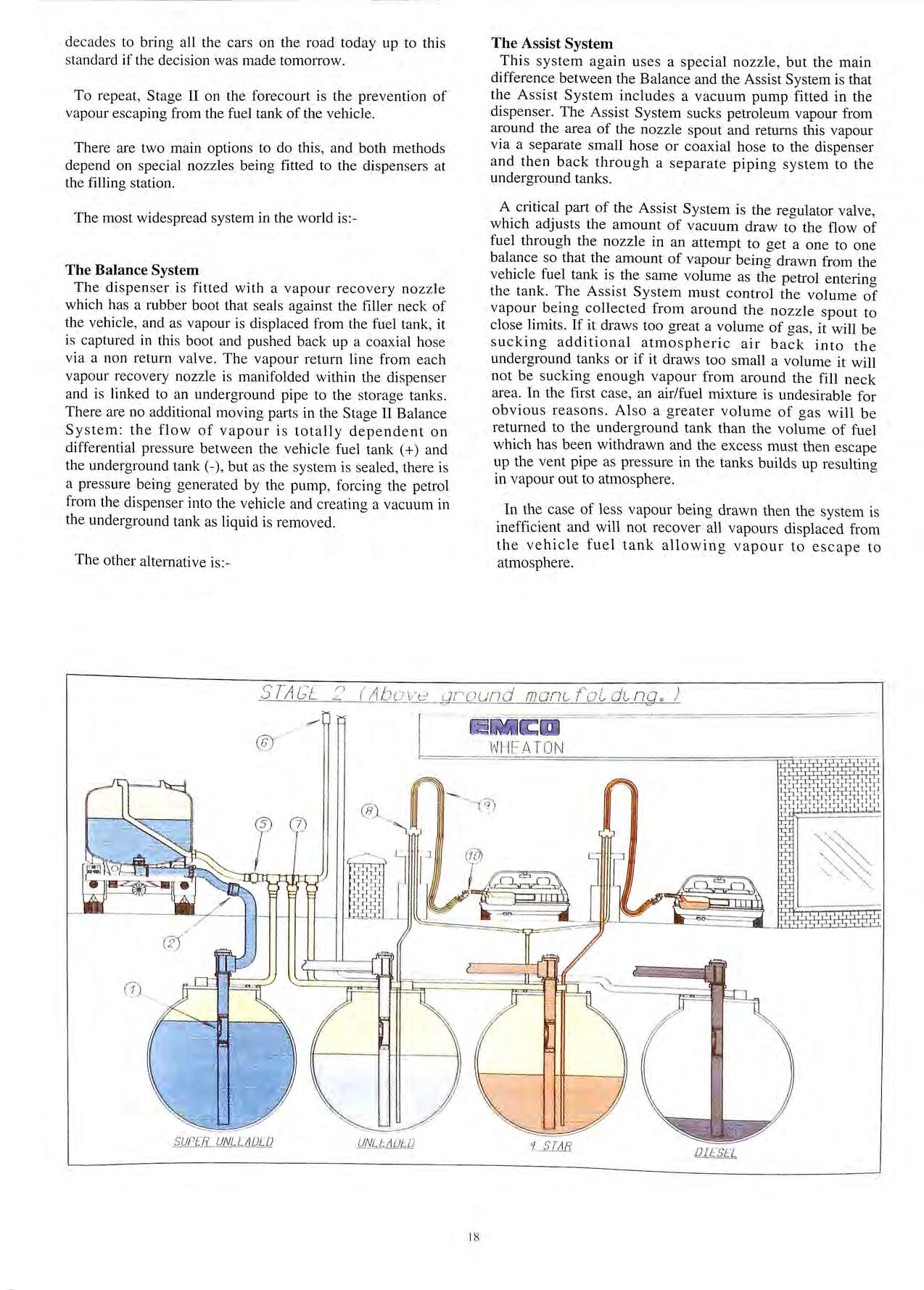
A critical part of the Assist System is the regulator valve, which adjusts the amount of vacuum draw to the flow of fuel through the nozzle in an attempt to get a one to one balance so that the amount of vapour being drawn from the vehicle fuel tank is the same volume as the petrol enterino the tank. The Assist System must control the volume of vapour being collected from around the nozzle spout to close limits. If it draws too great a volume of gas , it will be sucking additional atmospheric air back into the underground tanks or if it draws too small a volume it will not be sucking enough vapour from around the fill neck area. In the first case , an air/fuel mixture is undesirable for obvious reasons. Also a greater volume of gas will be returned to the underground tank than the volume of fuel which has been withdrawn and the excess must then escape up the vent pipe as pres sure in the tanks builds up re sulting in vapour out to atmosphere.
In the case of less vapour being drawn then the system is inefficient and will not recover all vapours displaced from the vehicle fuel tank allowing vapour to escape to atmosphere.
)
ST/'i.CE
18
2
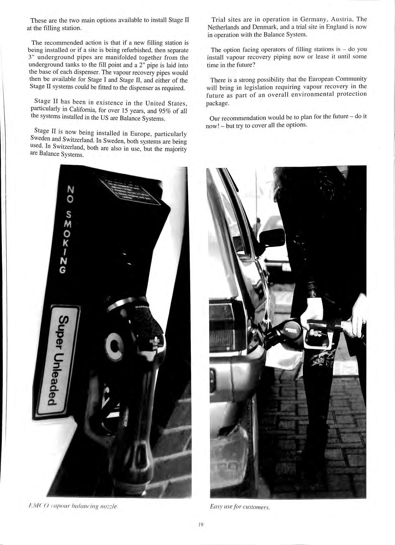
These are the two main options available to install Stage II at the filling station.
The recommended action is that if a new filling station is being in stalled or if a site is being refurbished , then separate 3" underground pipes are manifolded together from th e underground tanks to the fill point and a 2" pipe is laid into the base of each dispenser. The vapour recovery pipes would then be available for Stage I and Stage II, and either of the Stage II systems could be fitted to the dispenser as required .
Stage II has been in existence in the United State s particularl y California, for over 15 years, and 95 % of ali the sys tems mstalled in the US are Balance Systems .
Staae II is b · · "' now emg m sta lled in Europe, particularly Sweden and Switzerland. In Sweden, both systems are bein a used I s · . 0 · n w1tzerland, both are also m use, but the majority are Balance Systems.
Trial sites are in operation in Germany , Austria , The Ne therlands and Denmark , and a trial s ite in England is now in operation with th e Balance System
The option facing operators of filling stations is do yo u install vapour recovery pipin g now or lea se it until so me time in the future ?
There is a strong po ss ibility that the European Community wili bring in legi s lation requiring vapour recovery in the future as part of an overall environmental protection package.
Our recommendation would be to plan for the future do it now! but try to cover all the options.
FMCO t'o p n ur hol a n c ing no zz le. 19
sy use f
r cu s tom ers.
Ea
o
PUMP - WINNING FAVOU R IN EUROPE
By John Walker, Technical Manager, Charles S Madan & Co.
The development of Stage II vapour rec over y during car r e fu e llin g continues t o ga ther pace across Contin e nt a l E urop e.
Spurred on by economic, e nvironm e ntal and legislative press ur es, many leading European o il companies, dispen se r manu fact urers and forecourt red eve lopment contractor s a re now ac ti ve ly in v olved in Stage II recove ry trials , with so m e co mp a ni es already implem e ntin g vapour reco ve r y practi ces.
As a sp ec iali s t manufa c ture r of press ure pump s, di a phrag m pump s, vac uum pump s a nd co mpresso rs, Charles S Madan already s upplie s a va ri e ty of product s to the petroleum indu stry worldwide.
Passive v active system
R esearch confirmed th a t p e trol pump recovery techniqu es o n the C o ntinent favoured the 'act iv e' sys tem , or ' p os itiv e s u c ti o n ' of vapour fume s in prefe renc e to the ' pa ss iv e' o r ' b a la nc in g' sys tem u sed in p a rt s of th e USA.
ln A m e ri ca th e petrol pump di spe nse no zz le is fitt e d with a b e ll ows which creates a sea l aga in s t the filler pip e of the car so th at th e vapour is un a bl e to esca p e a nd a ' b a l a n c in g' pressure, crea ted by inc o min g fuel , fo rces the vapour b ack int o th e underground tank.
The sys te m works well but req uir es a s tandard s ize d filler n eck o n a ll cars and a uni ve r sa l pump no zz l e. Thi s i s possible in the USA s in ce American car filler n ecks are manu fac tured to SAE s tandard s a nd are th e sa m e s p ec ifi ca tion on diffe r e nt ca r m ode ls in th e m ajor it y of cases.
However , E urope thi s type of recove r y sys te m wo uld be d1ff1cult to 1mp.lement du e to the disparity b e tw ee n ca r m ode l s, eac h With a di ffe r e nt s i ze of tank filler neck. A univ e r sa l pump noz z l e s ize i s th e r efo re not applicable. drawback with th e balancing sys te m of recove ry is th a t it is c umber so m e a nd awkward to h a ndle
Wi t h the ac ti ve sys te ( f m 0 1 p os 1t1 ve s uction of va p o ur um es) ex 1s trno or new u· 1 · · · l ' 0 p e o pump s a r e fitted with coax 1a hose a nd nozz le. Th e va p o ur fuine s a. · 1 d ff at . . 1e ac ti ve y rawn o the pomt of di sp e n s in g a nd ret urn ed to the fu e l s to rage ta nks by a vacu um va pour pump h ouses in the pe trol dispen se r pump cas mg.
V ac uum for :a po ur recove ry th erefo r e need to be hi g hl y fl ex ibl e m co nfi g uratio n , li g ht we ig ht a nd compact in s i ze to p rov id e state-of-t h e-art ve r sa tilit y fo r r et r ofit in s tallation. Pump s a l so h ave to possess o ut s tandin g durabilit y a nd be Slllt a bl e fo r co nvey in g petroleum vapo ur in a h aza rd o us e nv iro nm e nt.
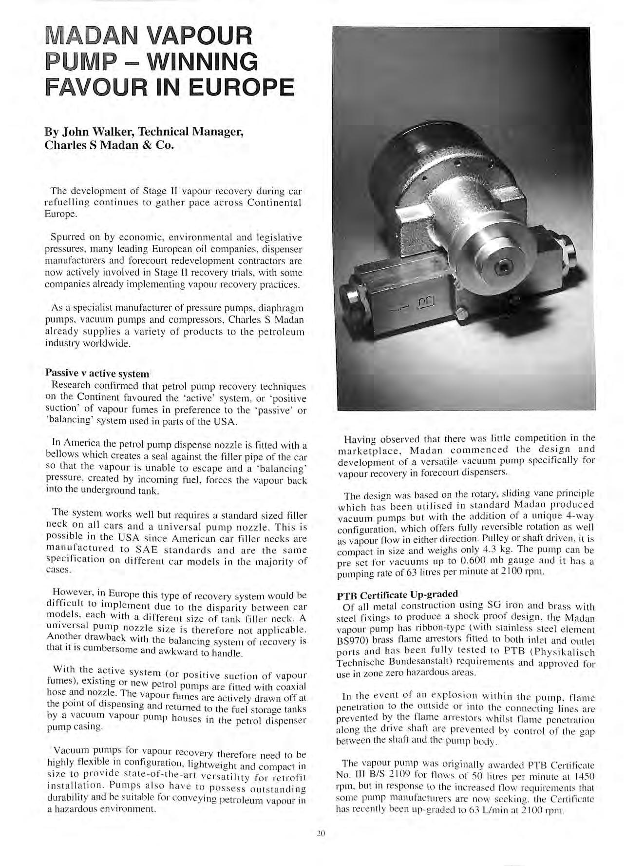
Havino observed that th ere was littl e competition in the b marketplace , Madan co mm e n ce d the de.s.1g n a nd development of a versa tile vacuum pump spec 1fJca ll y for vapour reco very in fo r eco urt dispensers.
The desi g n was based o n th e rotary , s lidin g va ne prin c i p le which ha s b ee n utili sed in s t a ndard Mad an produced vac uum pump s but with th e a ddition .of a uniqu e 4-way co nfi o urati o n , which offe rs fully re ve rs ibl e rotation as we ll as va;our flo w in e ith e r direction. Pull ey o r sh aft driven , it is co mp ac t in s ize a nd weig h s o nl y 4.3 kg. Th e ca n be pre se t for vac uum s up to 0 ..6 00 mb ga u ge a nd 1t h as a pumpin g rat e of 63 litres p e r mmut e a t 2 100 rp m.
PTB Certificate Up-graded
Of a ll m e t a l co n st ru c ti o n u sin g SG iron and brass w ith s tee l fixin gs to produc e a s hock proof design , the M ada n va pour pump h as ribb o n-typ e _(w ith s t a inl ess stee l e le m e nt BS970) bra ss flame arresto rs titl ed to b o th inl e t a nd o utl e t p o rt s a nd h as be e n fully t es t ed to PTB (P h ys ik a li sc h Technische Bund esa n s talt) re quirements a nd a pp roved for u se in zo ne ze ro haza rd o u s a reas.
Jn the eve nt of a n e.x pl os io n w ithin th e pump . flam e pen e tr a ti o n to th e o ut s id e o r int o th e co nn ec tin g lin es a re prevented by t he flam e a rr es tor s w hil s t fl a m e pe ne tration a lo ng th e drive s h aft are preve nt e d b y co nt ro l of th e gap betw ee n the s h aft a nd th e pump bod y .
The va po ur pump was o ri g in a ll y awa rd ed PTB Cert ifi cate No. III B IS 2 109 for fl ows of 50 litres pe r minut e a l 1450 rpm , but in respo n se to th e in c rease d flow req ui remen ts that so me pump m a nu fact ur e rs are now seek in g. the Ce rtificate h as rece ntl y bee n u p-graded to 63 Umi n a t 2 100 rpm
ADAN
VAPOUR
20
Madan use only quality selected metals in vapour pump manufacture and each individual part is electroless nickel coated for protection against corrosion. The pump i s th e refore of strong and dur abl e construction and there are no limit s to closed suction (ie runnin g time). Tested under a dv erse conditio ns with petrol a nd water dripping into th e unit , the durability of pump blades is guaranteed for a minimum of 5000 hours
Operation
The pump has a stator eccentrically mounted to the rotor. Th e rotor is s lotted to carry 4 vanes which, under operation conditions , move out by c e ntrifug a l action to form chambers w ithin th e s tator. The s ize of the chamber varies a s th e rotor rotates The inlet is a rran ge d to connect to the chamber when it is small and as th e rotor turn s the pressure drop s ( Boyl es Law) and air flows into the unit due to the difference in pre ss ure betw ee n th e a tmo s phere and the in side of th e chambers. This change is very small for each chamber but at 2100 rpm it happens 8400 times per minute (4 x 2100 ).
The air is expelled from the unit by raising the pre ss ure to e n a bl e it to o v ercom e atmospheric pressure a nd a ny re s ista nce due to fittin gs etc. To ac hi eve thi s the outlet of th e pump is connected to a s mall c hamb er formed by th e va ne s a dj ace nt to the inlet chamber.
Air e nt e r s the pump throu g h the inlet port fitted with a 25mm dia x lOmrn wide ribbon-typ e flame arrestor and is ex h a u ste d b y openin g th e non return valve and pa ss in g through a s econd and sim ilar flame arrestor in the outlet po rt.
A c ro ss -line relief va l ve is in co rpo ra te d in the unit whi c h pre ve nt s ove r pre ss ure if th e o utl et is blocked Th e openina p re ss · f h. · "' ui e o t is va lve 1s se t b y s pring. Th e outlet non return va l ve ope nin g pres s ur e is ve ry s mall a nd is se t by sp rin a. Th e fr f f · · "' 1n c ion o thi s va l ve 1s to prevent any blo w back int o the pump
It is s uppli ed fully te s te d in the co nfi g uration ordered and re quires no -1 · · 1eg u a1 m a 111t enance. However, as w ith any ope n sys t e m w h ic h t akes in vapo ur , it is po ss ible fo r fo re i a n matt e r to be t· k · h . '=: d e n 111 t 1o ug h the nozz le. This mi g ht re s ult 111 th e m a lfun c ti o n of the pump unit a nd s impl e tec hni ca l c heck s a nd 1d v 1 .ce · · · h · · ' ai e g1 ve n w it 111 s truct1on s
Air flow / vapour flow
Us in g the Madan va po ur pump , it is presently po ss ibl e to rn a tch a i · fl I 1
ow a nc pet1 o l vapou r w ith a reaso nable dearee of acc ur acy by 1n ec h 1111· ca l I · ff. "' · ' va ve operat io n. c urrent e · ic 1e nc1es in v apour recove ry a re in the orde r of 80 %
Ho weve r f urth e r effic ie nci es co uld we ll be pro v id ed by in troduc in g a n e l ec tr o -rn ec hanical sys t e m to m atc h va po urh ir f' I d M d · · ' ow a n a a n a re pr ese ntl y work 111 g 1n coop e ra tion w ith a not he r co rnpan y to d eve lop s uc h a s ys te m.
T hi s lat es t Mada n p rod uc t fo r th e va pour recove ry m a rk e t ha s c r e a te d c o n s id era b le int e res t wo rld w id e a nd is be in g 1e d to petro l pump d is pen se r m ake rs Dre sse r Wayn e i 1--:urnp e ! of E in bec k Ge rm a n y, f o r bot h re trofit a nd o ri g inal l' LJUipm e nt u se In add iti o n seve r a l le adi n g E u rop e an o il L ' (l lllpa ni e \ and ot h e r di s p e n se r manu fact ur er s h a ve th e \ <1 p1 >Ur recove r y pump on tes t.
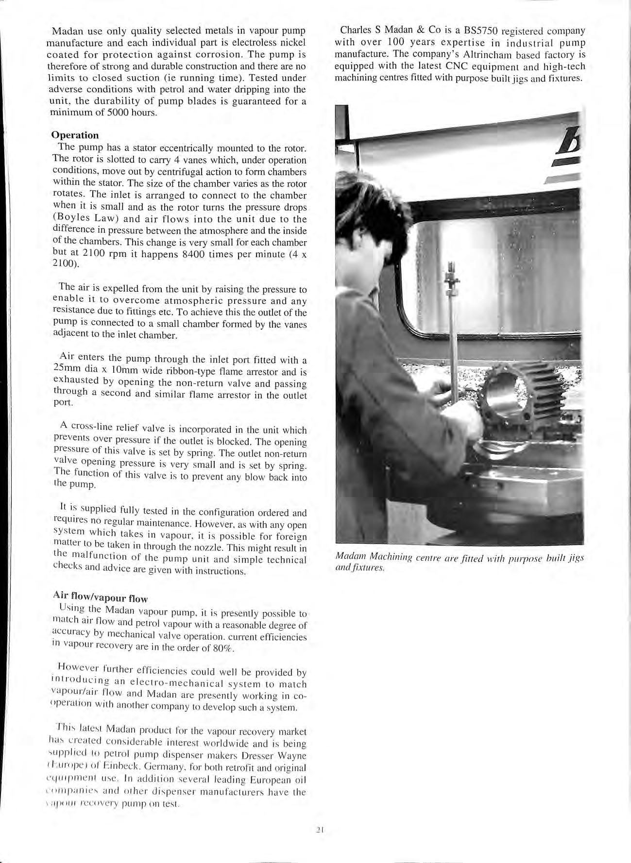
Charles S Madan & Co is a BS5750 re g iste red com p a ny with over 100 years ex p e rtise in indu s tri a l pump manufacture The company's Altrincham ba se d factory is equipped with th e late s t CNC equipment a nd hi g h-t ec h machining centre s fitted with purpo se built ji gs and fi x tures.
2 1
Madam Machining cen tr e are .f11ted w ith pwp nse built jigs and fixture s
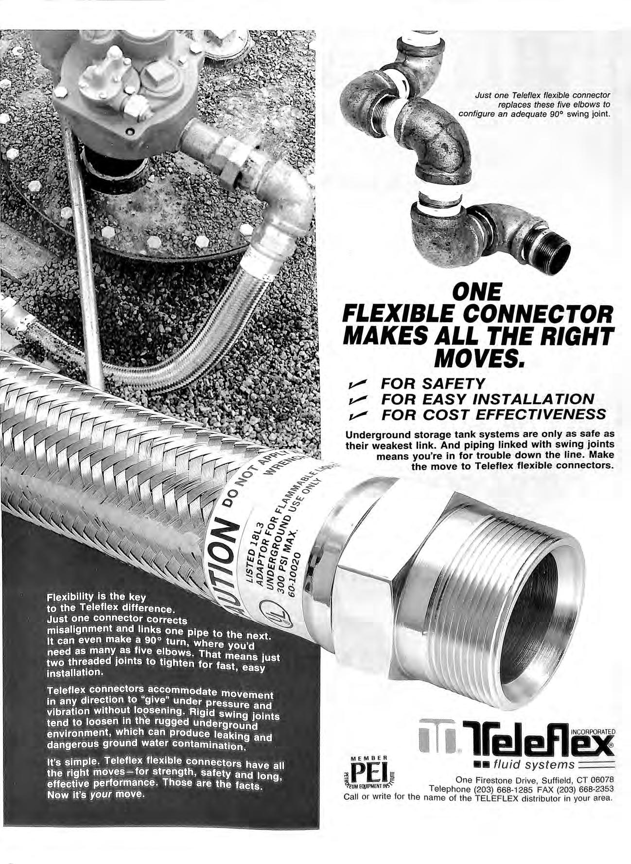
ONE FLEXIBLE CONNECTOR MAKES ALL THE RIGHT MOVES. v FOR SAFETY v FOR EASY INSTALLATION v FOR COST EFFECTIVENESS Underground storage tank systems are only as safe as their weakest link. And piping linked with swing joints means you're in for trouble down the line Make the move to Teleflex flexible connectors. MEMBER PEI ••fluid systems !} One Fi restone Drive , Suffield , CT 06078 MR!lfl'MENT.1 Telephon e (203) 668 1285 FAX (203) 668-2353 Call or write for the name of the TELEFLEX distributor in your area.
Just one Teleflex flexible connector replaces these five elbows to configure an adequate 90° swing joint.
DEWCO OIL SERVICES LTD NATIONAL 24 HOUR SERVICE IN RECTIFICATION OF SPILLAGES INVOLVING OIL PRODUCTS EMERGENCY 24 HOUR: 081-805 1856 GENERAL ENQUIRIES: 081-804 1095 INSTALLATION COMMISSIONING & SERVICE ' OF SPECIALISED LEAK/SPILL PREVENTION EQUIPMENT ASSOCIATED WITH PETROLEUM PRODUCTS ENQUI RI ES PLEASE CONTACT: DEWCO SALES & MARKETING DEPT. DEWCO OIL SERVICES LTD DEWCO HOUS E, 587 HERTFORD ROAD , E N F IELD WA S H E N3 SUL Tel : 081-804 1095 · 08 1-804 7677

*Quazar THE SIGN OF QUALITY. EADERS ON FOR COURT AND ETROLEU STREETS AHEAD (JJ) LTD UNIT 3 , SUPER ABBEY ESTATE , BEDDOW WA Y , AYLESFORD , KENT, ME20 7 BH ENGLAND TEL: 0622 79222 FAX: 0622 790099 SR SAE MANUFACTURERS AND DISTRIBUTORS OF PROMOTIONAL SIGNS AND SAFETY EQUIPMENT.SUPPLYING: POLICE EMERGENCY SERVICES* UTILITIES* MARINE AND AVIATION* ADVERTISING * PROMOTION INDUSTRIES ( O.S.11.11 SYMBOL SIGNS High Visibility Garments mad e to Briti s h Standard 856629: 1985 OTHER PRODUCTS AVAILABLE: RIGID SIGNS, CONES FLASHING LAMPS, MANHOLE GUARDS, BARRIER BOARDS, WINDOW STICKERS, CYCLE AND EQUESTRIAN SAFETY Special signs made to order C p INSTALLATIONS LTD. (Established 1968) Specialists in Petroleum Pipework Installations New and existing Tanks and Lines tested Modifications to existing Installations And all work associated with Forecourt Pipework Approved for UPP pipework installations and Enviroflex Approved for Ameron and Smiths Fibreglass installations 39 BROOK ROAD, RAYLEIGH WEIR INDUSTRIAL ESTATE RAYLEIGH, ESSEX SS6 7XN Tel: 0268 781184/781859 (24 hrs ans) Fax: 0268 776697

1963 .D :I I 3s GALLON INDEPENDENT PUMP SERVICES Pumps & Tanks (Shoreham) Ltd Est 1963 ADUR BOATYARD, OLD SHOREHAM ROAD SHOREHAM-BY-SEA, WEST SUSSEX, BN43 5TA 0273-454831 FAX: 0273-464863 199 1 43p LITRE A COMPANY STAFFED BY ENGINEERS CAPABLE OF MEETING THE DEMANDS OF MODERN FORECOURT SERVICE STATIONS •ALL PUMP TANK & PIPEWORK INSTALLATIONS FIBREGLASS & STEEL • LARGE MODERN FACTORY WfTH COMPLETE PUMP OVERHAUL TEST & REPAIR FACIUT7ES •LARGE PUMP STORAGE WAREHOUSE WfTH SPARES FOR MOST 7YPES OF EXISTING PUMPS BS5750 PART 1 QUALITY ASSURANCE CURRENTLY BEING WR ITTEN & DEVELOPED FOR DESIGN, INSTALLATION & SERVICE & S STANSFIKl,IJ IJMITIUJ¥ Petroleum Installation Specialists Approved Installers For Fibreglass and Plastics Unit 10 Bounda ry Roa d Indust rial Est at e Sturmer, Haverhill Suffolk, CB9 7YH Tel: 0440 712505 Fax: 0440 712506
CAPITAL DEMOLITION <NHEJ LTD Specialist removal of fuel tanks General demolition Concrete breaking BYFLEET (09323) 46222 41525 46005 D.M. PETROLEUM SERVICES Proprietor:- D. B. MAJOR Telephone: 0462 732418 Specialists in Forecourt Pipework Installations Ameron Approved Installer 25 Brook Street, Stotfold Mobile Telephone 0836 280239 Hitchin Fax 0462 732418 Hertfordshire SG54LA
ALL YOUR FORECOURT REQUIREMENTS ARE UNDER ONE ROOF Gl SQ Overfill Preven!ion val\le •Tanks •Vapour Recovery •Overfill Prevention • Contents Gauging •Spill Containers --=====-----=----=--------11-VF Vapor reco11ery nozzle •Pumps • Hoses •Nozzles •Valves • Breakaways ---Coax1a deli11eryhose 66 Breakaway connector 11 -AP Au1omat 1c nozzle non lead 10-RF Emergency shut-ott valve /Pump Farm The Fuel Dispensing Specialists PUMP SERVICES (MANCHESTER) LTD,, WE STERN PARKu KANSAS AVENUE, SALFORDu MANCHESTER M5 2GL TELEPHONE 061 873 7428 FAX 061 848 7193
LOXDENE LTD FORECOURT SERVICES Established 1984 CERTIFIED AND EXPERIENCED AMERON GRP INSTALLERS PURPOSE DESIGNED ALL WEATHER INFLATABLE TRENCH COVERS FOR WORKING WITH GRP PIPE CONVENTIONAL STEEL PIPE INSTALLATIONS NATIONWIDE SERVICE 45 Vivian Avenue Hendon London, NW4 3XA APEA MEMBER Tel: 081-202 8035 Fax: 081-202 1642 GRAHAM WHITE GARDEN SERVICES Specialists in Forecourt Landscaping, offering National Landscaping Services to all the Oil Companies (Established 10 Years) 7 GLENHAM ROAD , LEA PARK , TRAME , O X ON OX 9 3 W D TELEPHONE: THAME (084 42 1) 7134
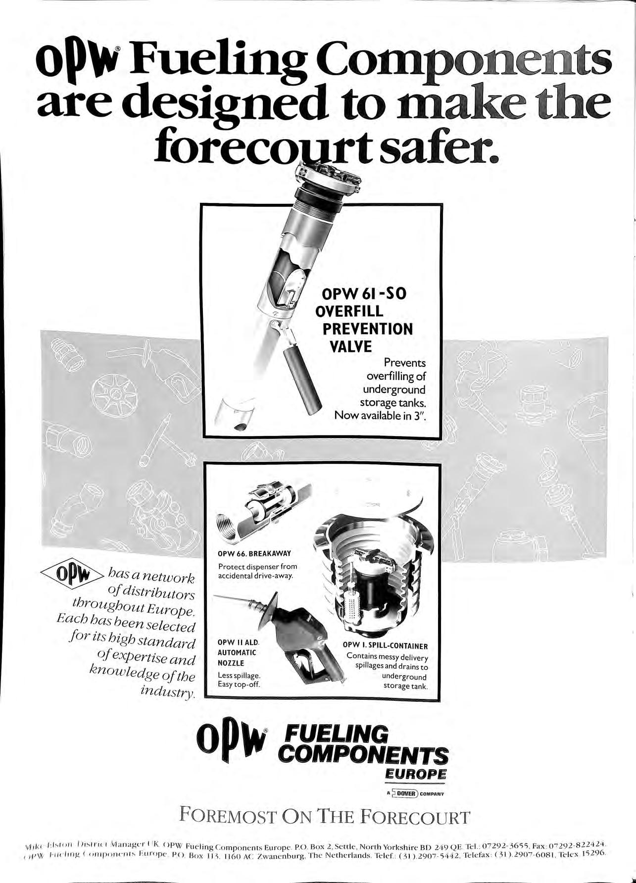
oP\V Fueling Coinpone t s are designed to inake the forecoJ.l(t safer. Protect dispenser from accidental drive-away. OPW II ALO. AUTOMATIC NOZZLE Less spillage Easy top-off. Cf OPW 61-SO OVERFILL PREVENTION VALVE OPW I. SPILL-CONTAINER Contains messy delivery spillages and drains to underground storage tank op\V FUELiNG COMPONENTS EUROPE A DOVER) C OMNNV F OREMOS T ON T I-IE F OREC O URT VI 11< (' L hi• ' 11 1Jisl l 'JCI M an ag<" r I II( O PW Fu e li ng Com po n en ts Eu ro p e. PO Box 2 , Sett le, No rth Yo r ks hi re BD 2 4 9 QE k l. : 0 7292 3 655 Fax : ( 1pW /'l l<'lmg < umpon t'n!s ' ""rope , P O Box tn . 1160 AC Zwane n bu r g , Th e Ne th e rl an ds Telef: (3 1 ) 2907 5 442, Te l e fax : D I ) 2907-6 0 81. Telex h 296.
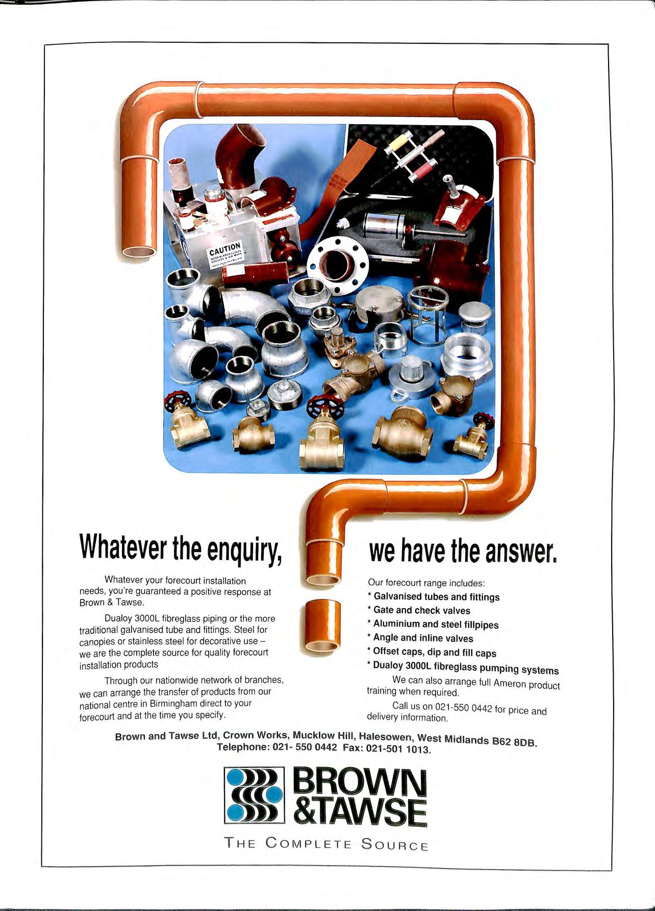
the enquiry,
Whatever
we have the answer. Our forecourt range includes : * Galvanised tubes and fittings * Gate and check valves
• Aluminium and steel fillpipes
• Angle and inline valves
*Offset caps, dip and fill caps
products * Dualoy 3000L fibreglass pumping systems
We can also arrange full Ameron product
training when required.
Call us on 021-550 0442 for price and
delivery information. Brown and T awse Ltd, Crown Works, Mucklow Hill, Halesowen , West Midlands s 62 808 Teleph
Fax: 021 501 1013 · BROWN &TAWSE THE C OMPLETE S OURCE
Whatever your forecourt installation needs, you're guaranteed a positive response at Brown & Tawse.
Dualoy 3000L fibreglass piping or the more
traditional galvanised tube and fittings. Steel for
canopies or stainless steel for decorative use we are the complete source for quality forecourt
installation
Through our nationwide network of branches,
we can arrange the transfer of products from our
national centre in Birmingham direct to your
forecourt and at the time you specify
o ne : 021 · 550 0442
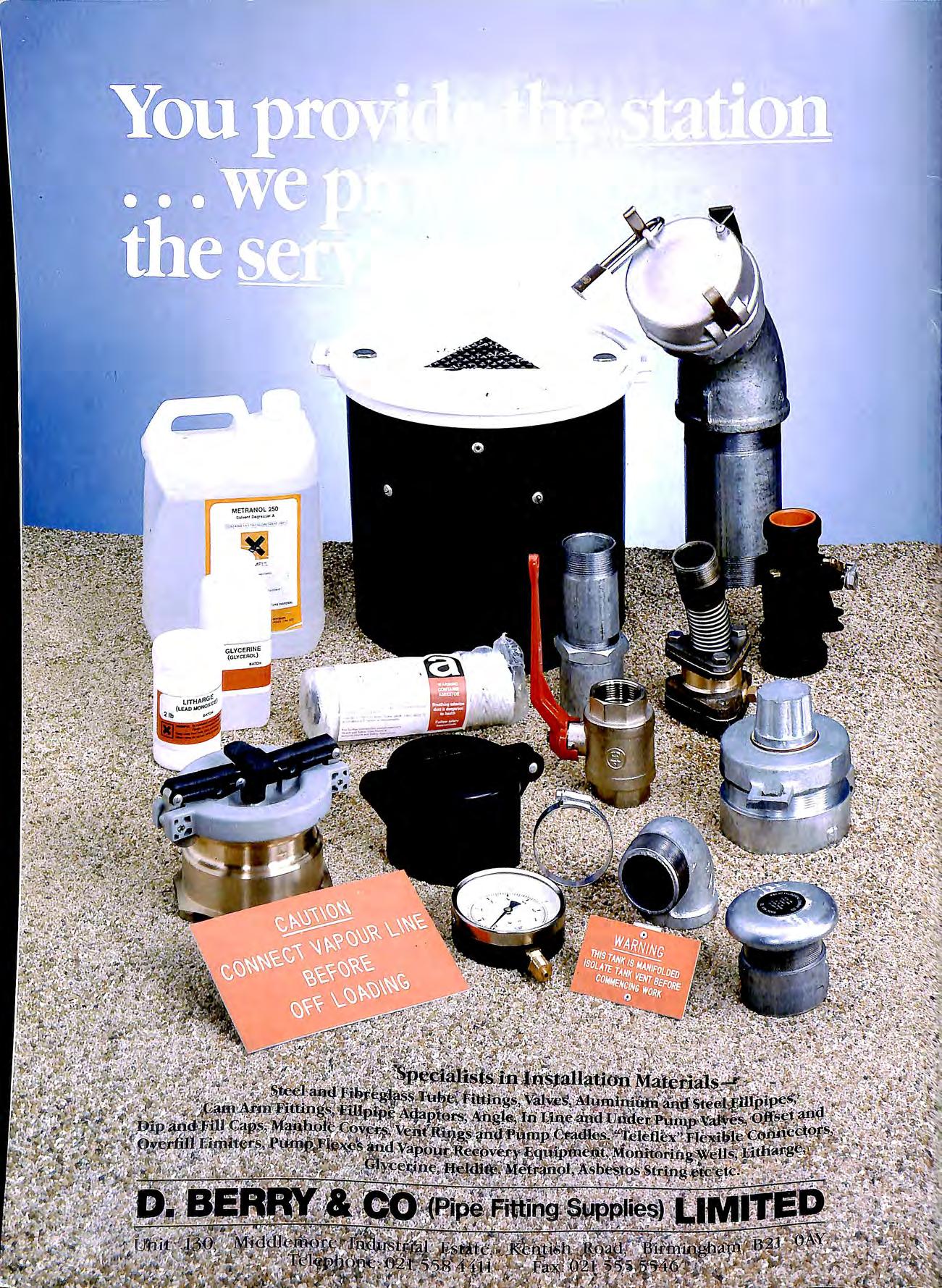
METRANOL 250 !.Ol °"1' •"'" • ;-1-:
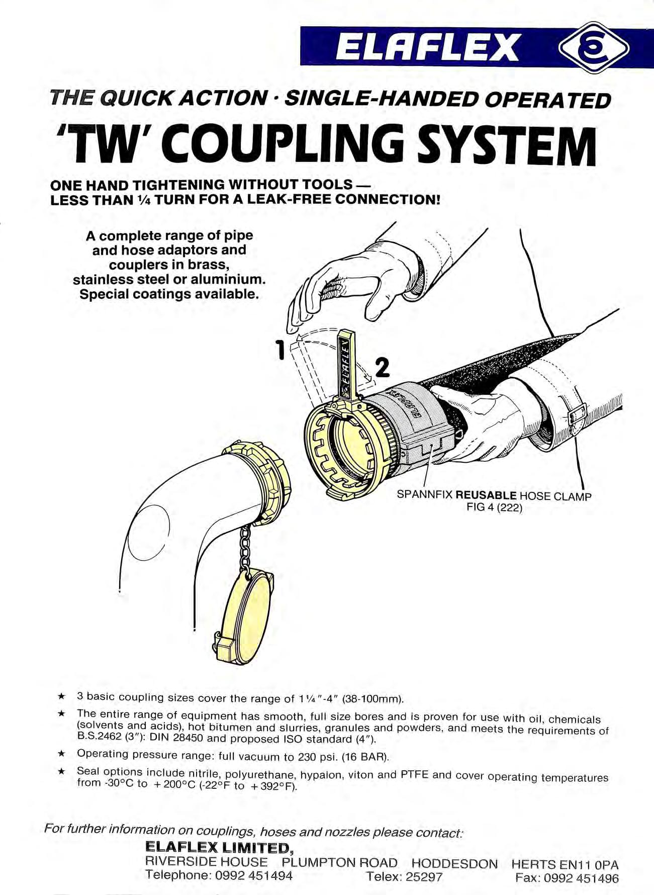
El.RFl.EX THE QUICK ACTION· SINGLE-HANDED OPERA TED 'TW' COUPLING SYSTEM ONE HAND TIGHTENING WITHOUT TOOLSLESS THAN 1/4 TURN FOR A LEAK-FREE CONNECTION! A complete range of pipe and hose adaptors and couplers in brass, stainless steel or aluminium. Special coatings available. * 3 basic coupling sizes cover the range of 1 % "-4" (38-100mm). * The entire range of equipment has smooth, full size bores and is proven for use with oil, chemicals (solvents and acids), hot bitumen and slurries, granules and powders , and meets the requirements of B.S.2462 (3"): DIN 28450 and proposed ISO standard (4 " ). * Operating pressure range: full vacuum to 230 psi. (16 BAR) * Seal options include nitrile, polyurethane , hypalon , viton and PTFE and cover operating temperatures from -30°C to + 200 ° c (-22 ° F to + 392 ° F) For further information on couplings, hoses and nozzle s please contact: ELAFLEX LIMITED, RIVERSIDE HOUSE PLUMPTON ROAD HODDESDON HEATS EN11 OPA Te lephone : 0992 451494 Te le x: 25297 Fax: 0992 451496
: . .. \\Tast e O iL (oll e c t i o n and R ' larnati )Jl Ta n k Cleanin g , G e neral Cl t> aning and E n erg ' nc y Oil Spill · g e Sen·i ·e s . Other Services offered: Cleaning of All Tanks, i.e. Spirit, Oil, Chemical, Water. Shot Blasting and Painting of Tanks, Tank Removal. Descaling of Pressure or Condensate Tanks. Pressure Testing of Tanks and Pipes Interceptor Pit Clearance. Removal of Vessel Bilge Sludge and Fuel Oil Slops. HEAD OFFICE: Cecil House, 27 High Street, Hoddesdon, Herts ENll SUZ Telephone 0992 451848 Facsimile 0992 ·446596 DEPOTS: Hoddesdon The Lodge, Essex Road, Hoddesdon, Herts ENll OAT Telephone 0992 451090 Facsimile 0992 451 091 Erith Maypole Crescent, Darent Industrial Park, Slade Green, Erith, Kent Telephone 0322 347402 Felixstowe SubcStation Road, The Dock, Felixstowe, Suffolk IPll SSE Telephone 0394 272236 Telex 0206 987185 COMTLX-G Wokingham Langley Common Road, Berkbam, Nr Wokingham, Berks RG 11 4TS Telephone 0734 760253 Great Yarmouth 5 BrineU Way Harfreys Industrial Estate, Great Yarmouth, Norfolk NR31 OLU 9 Telephone 0493 602848 Facsimile 0493 655459
