The •
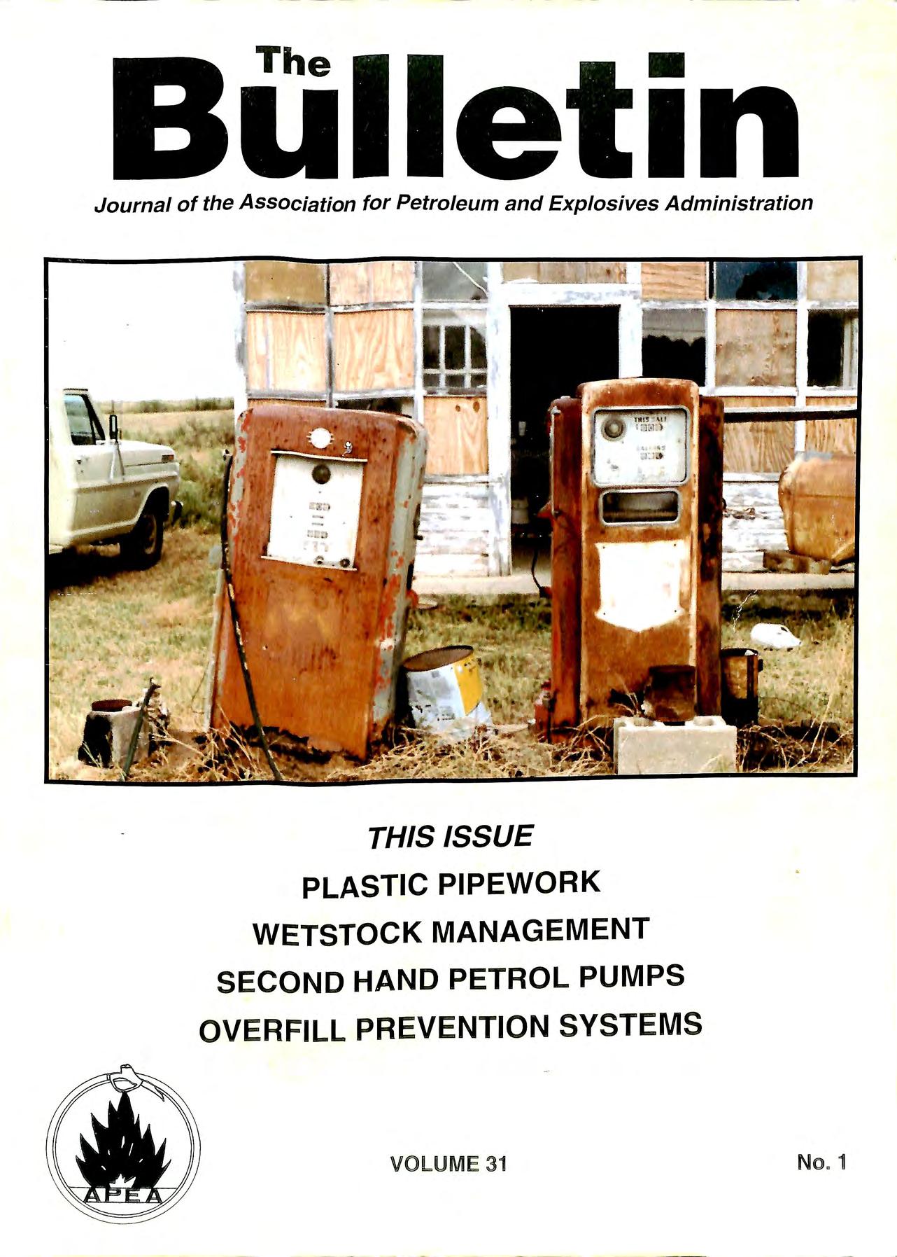
THIS ISSUE PLASTIC PIPEWORK WETSTOCK MANAGEMENT SECOND HAND PETROL PUMPS OVERFILL PREVENTION SYSTEMS VOLUME 31 No" 1
Journal of the Association tor Petroleum and Explosives Administration

If you're rebuilding your station, you're probably in a rush for the pipe to be in the ground and tested so you can get on with your real business of selling fuel.
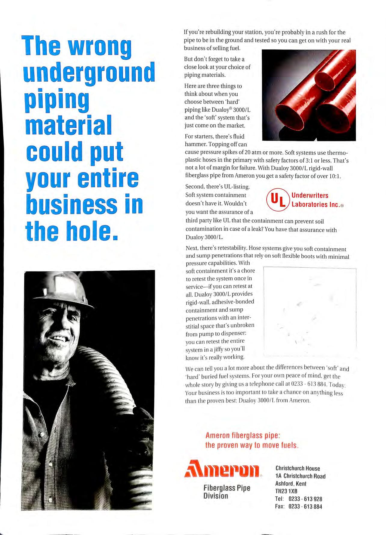
But don't forget to take a close look at your choice of piping materials.
Here are three things to think about when you choose between 'hard' piping like Dualoy®3000/L and the 'soft' system that 's just come on the market.
For starters, there 's fluid hammer. Topping off can cause pressure spikes of 20 atm or more. Soft systems use thermoplastic hoses in the primary with safety factors of 3: 1 or less. That's not a lot of margin for failure. With Dualoy 3000/L rigid-wall fiberglass pipe from Ameron you get a safety factor of over 10: 1. Second, there's UL-listing. Soft sys tem containment do esn't have it. Wouldn't you want the assurance of a Inc @ third party like UL that the containment can prevent soil contamination in case of a leak? You have that assurance with Dualoy 3000/L.
Next, there's retestability. Hose systems give you soft containment and sump pen etrations that rely on soft flexible boot s with minim al pressure capabilities. With soft containment it's a chore to retest the system once in service-if yo u can retest at all. Oualoy 3000/L pro vide s rigid-wall, adhesive-bonded ,( conta inment and sump penetrations with an inter- / stit ia l space that's unbroken from pump to dispenser: you can retes t the entire sys te m in a jiffy so yo u'll know it's really wo rking. We ca n tell you a lot more about th e differences betwee n 'soft' a nd 'hard' buri ed fuel systems. For you r own peace of mind , get the whole story by giving us a telep hon e ca ll at 0233 613 884. Todav. Your business is too import a nt to take a cha nc e on anything than the proven best: Dualoy 3000/L from Amero n.
In 1968 Underwriters Laboratories Inc. granted our Red Thread pipe the first-ever listing for underground fiberglass piping of petroleum products. Since then more than 20 · million feet have been installed far more than any other fiberglass brand With a performance record un surpassed by anyone .. and vastly superior to " holey" steel as you can see!
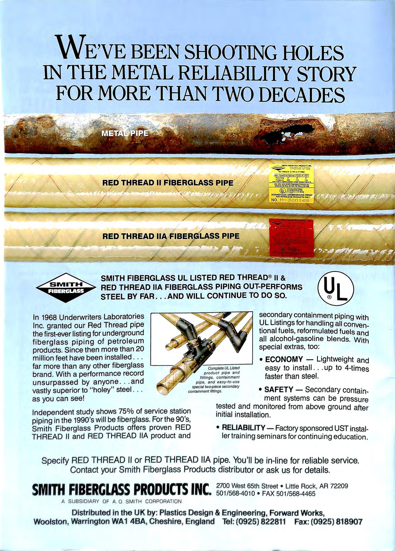
Independent study shows 75% of service station pipi ng in the 1990's will be fi berglass For the 90 's, Sm ith Fiberglass Products offers proven RED THREAD II and RED TH READ llA product and
secondary containment piping with UL Listings for handling all conventional fuels, reformulated fuels and all alcohol-gasoline blends. With special extras, too:
ECONOMY - Lightweight and easy to install ... up to 4-times faster than steel.
SAFETY Secondary containment systems can be pressure tested and monitored from above ground after initial installation.

Telephone: 0279 422050 Fax: 0279 433663


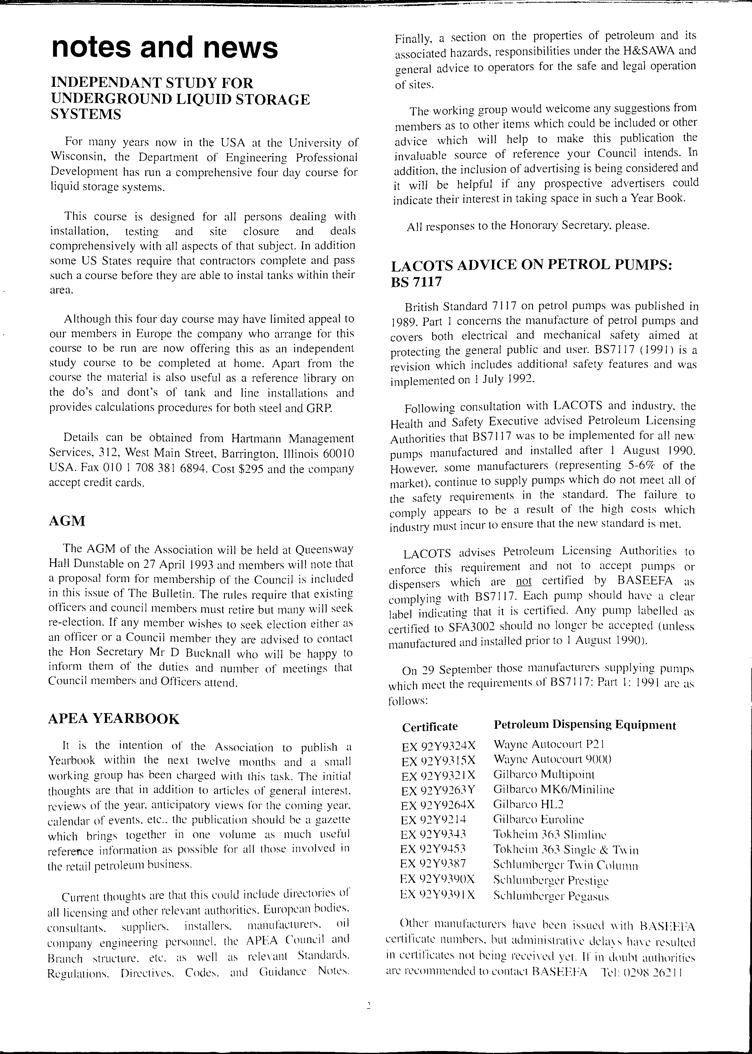
1993 heralds the Associations 35th anniversary and also 31 years of publication of the Bulletin. It seems from the comments that the Association has received this past 12 months, and the quest for knowledge and information from members in this quickly changing industry, that the Association is in for a very busy yea;. The structure of the ruling Council of the Association is changing to meet the demands that the membership is making on the Assoc1at1on and hopefully members will benefit from these changes which should be in place for this coming year.
Men;ibers will also look forward to publication later this year (fmgers crossed) of the revised HS(G)4 l which is urgently needed, and although this column has been critical in the past of the Jack of progress of the HSE in this area, there is a great deal of work going on in the HSE to prepare the draft for public comment.
The HSE is likely to revise its recommendations to licensing authorities on the vexed question of the removal of PME on existing filling stations and it is anticipated that a decision will be relayed to licensing authorities before the revision of HS(G)41.
For many years now in the USA at the University of Wisconsin, the Department of Engineering Professional Development has run a comprehensive four day course for liquid storage systems.
This course is designed for all persons dealing with installation, testing and site closure and deals comprehensively with all aspects of that subject. In addition some US States require that contractors complete and pass such a course before they are able to instal tanks within their area.
Although this four day course may have limited appeal to our members in Europe the company who arrange for this course to be run are now offering this as an independent study course to be completed at home. Apart from the course the material is also useful as a reference library on the do's and dont's of tank and line installations and provides calculations procedures for both steel and GRP.
Details can be obtained from Hartmann Management Services, 312, West Main Street, Barrington, Illinois 600 I 0 USA. Fax 010 1 708 381 6894. Cost $295 and the company accept credit cards.
The AGM of the Association will be held at Queensway Hall Dunstable on 27 April 1993 and members will note that a proposal form for membership of the Council is included in this issue of The Bulletin. The rules require that existing officers and council members must retire but many will seek re-election. If any member wishes to seek election either as an officer or a Council member they are advised to contact the Hon Secretary Mr D Bucknall who will be happy to inform them of the duties and number of meetings that Council members and Officers attend.
It is the intention of the Association to publish a Yearbook within the next twelve months and a small working group has been charged with this task. The initial thoughts are that in addition to articles of general interest. reviews of the year. anticipatory views for the coming year. calendar of events. etc the publication should be a gazette which brings together in one volume as much useful reference information as possible for all those involved in the retail petroleum business.
CuITent thoughts are that this could include directories of all licensing and other relevant authorities. European consultants. suppliers. installers. manufacturers. rnl company engineering personnel. the APEA Council and Branch structure. etc. as well as rclernnt Standards. Regulations. Directives. Codes. and Guidance Notes.
Finally, a section on the properties of petroleum and its associated hazards, responsibilities under the H&SAWA and aeneral advice to operators for the safe and legal operation e of sites.
The working group would welcome any suggestions from members as to other items which could be included or other advice which will help to make this publication the invaluable source of reference your Council intends. In addition, the inclusion of advertising is being considered and it will be helpful if any prospective advertisers could indicate their interest in taking space in such a Year Book.
All responses to the Honorary Secretary. please.
British Standard 7117 on petrol pumps was published in 1989. Part I concerns the manufacture of petrol pumps and covers both elect1ical and mechanical safety aimed at protecting the general public and user. BS7 l l 7 ( 1991 ) is a revision which includes additional safety features and was implemented on I July 1992.
Following consultation with LACOTS and industry, the Health and Safety Executive advised Petroleum Licensing Authmities that BS7 l l 7 was to be implemented for all new pumps manufactured and installed after . I August 1990. However, some manufacturers (representmg 5-6% of the market). continue to supply pumps which do not meet all of the safety requirements in the standard. The failure to comply appears to be a result of the high costs which industry must incur to ensure that the new standard is met.
LACOTS advises Petroleum Licensing Authorities to enforce this requirement and not to accept pumps or dispensers which are not certified by BASEEFA as complying with BS7 I l 7. Each pump should have a clear label indicating that it is certified. Any pump labelled as certified to SFA3002 should no longer be accepted (unless manufactured and installed prior to I August 1990).
Other manufacturL'rs have been issued with HASEEFA certificate numbers. but administrative ha\.L' resulted in ccrti ficates not being recei vcd yt'I. If in :iouht au\ horities are recommended to contact BASEEFA Tel: 0298 26211
The Branch was active throughout 1992 and since the last report in the Bulletin there have been meetings in Bristol and Eastleigh plus a site visit to the Esso Pipelines terminal in Fawley.
The Bristol meeting took place on 4 June 1992 at the County of Avon Fire Brigade Headquarters and was attended by over 50 members. The theme of the meeting was "Non-Metallic Pipework" and presentations were made by Jamie Thompson (LFCDA) who gave a licensing authority overview, Richard Graham (Ameron) who presented Ameron GRP pipework, Paul Chawner (Purfleet Commercials) who presented Enviroflex pipework, John Baudry (PetroTechnik) who presented UPP pipework, and Han Meenhere (EPACT & Wavin Repox) who presented the ?oints of view of both of these organisations. The meeting mvoked a lively question session although some members were disappointed that the presentations were somewhat spoiled by "commercialism'' which resulted in a degree of undue criticism of competitors' products.
A further visit took place on 30 September 1992 when the attended the Esso Pipelines Terminal at Fawley. The meetmg was hosted by Jian Buchan of Esso who gave a detailed insight into the operation of Esso's national pipeline network.
On 16 November 1992 a meeting was held at the Fire Brigade HQ in Eastleigh when the subject for discussion was "Environmental Protection at Petrol Filling Stations". Presentations were made by Ian Larkins of the National R" · S 1vers Authority, Mike James of Land Restoration ystems Ltd, Robert Bridges of Thyme Management Ltd and Gerry Risbridger of W & J Risbridger Ltd.
The next Branch meetino will be the AGM which is to be held i S · "' n on 17 February 1993 which apart from the busmess will include presentations on the subject of Pressure Pumping Systems".
In ·1dd"f · Co '. 1 Ion to the main meetings. the Branch Executive S mmittee meets regularly. under the chai1manship of Mike ewell. to B . h · . carry out general management of the 1anc including th f" · f . e arrangement of meetinos and the exchange 0 111 ormation between the Branch and APEA Council.
Members 1·n th B · · d ta1·1s f· · e ranch area should be rece1vmg e · . 10 m the Branch Secretary of all events If any member is concerned h· B t at details are not being received then the ic1nch Se h address :h cretary. Jim Luke. should be contacted at t e · · s own on the lead page of the Bulletin.
Two exam I Fd't· P es of the misuse of NICEIC forms of l Sth ' ion Com I t" th·tt (' . e H>n Certificates have come to the notice of ' ouncI) in iecent months.
In the first incid · II d ent an electrical contr·1ctor who was not l:"lllo e with tl N , , \J /('f- IC f IC El C. had ohtaincd and issued an I : o1111 of Completion Ccrtifinte for work he had 11111 l'llakcn. In th . , . ' . . " . . e second case. a huilding contractor had llldlld,-Ld lo ohta1n the N!C'EJ(" c· c· ·1·· t· f" rn , omplet1011 e111 Ka c o 1 .111d lwd 11;1-....,ed 11 on t<> 111· · I · · · I · s e ectncian tor comp etion.
The Council is providing the requisite evidence to the Local Authorities to enable the respective Trading Standards Departments to prosecute the non-Approved contractors concerned.
The Approved Contractors, from whom the Completion Certificate forms were obtained or purloined, have been asked to provide an explanation and reminded of their obligation to the Council.
An Approved Contractor who knowingly provides an NICEIC form of Completion Certificate to another contractor, either freely or for gain, may not be aware of the consequences of his actions. Deception is, of course, a criminal offence: it's 'on-the-record'.
The Approved Contractor also renders himself liable to removal from the Roll. The transfer of the NICEIC form of Completion Certificate from one individual to another may not be known to the authorised holder ie: the Approved Contractor. It is in the latter's interest to ensure that NICEIC Certificate forms issued to him are kept under his control at all times. It is most important that the confidence that specifiers and consultants have in NICEIC forms of Certificate is not jeopardised.
To help petrol retailers make the necessary changes to the identification and labelling of their storage tanks, as required by new legislation, Veeder-Root Environmental Services Normand CMS has introduced a new, flexible service that should help all sites meet the regulations.
The Road Traffic R_egulations 1992 (Carriage of Dangerous Substances m Road Tankers and Tank Containers), require storage tanks to be clearly marked with the tank number, grade of fuel and "any reference to the maximum working capacity of a storage tank shall be a reference to 97% of its actual capacity, expressed in litres". All sites must comply with the regulations by 30 June 1993.
In effect this means that if sites do not cun-ently meet these requirements:
new labels must be fitted to tanks and offset fills. dipsticks should be engraved or marked to match the tank labels. tank gauges. electronic or analogue, should also match the new labelling and capacity requirements.
Veeder-Root's new service accommodates these requirements, by either supplying the new grade labels for site operators to apply themselves or by providing a complete package including the fitting of labels as well as supplying new dipsticks or re calibrating tank gauges.
Charges vary depending on individual site requirements. hut as the leading supplier of dipsticks and grade labels. as well as electronic and analogue gauges. Veeder-Root is ahle lo supply the most cost-effective solution to meet site needs.
For further details of the new service. petrol retailers contact Veeder-Root 081 392 1355.
A detailed technical paper describing the effects of water penetrating the surface of concrete block paving, has just been published by Advanced Construction Materials Ltd. (ACM), with the permission of the author Professor John Knapton BSc., PhD., C.Eng., FICE, FIHT, MConsE.
Increasing U.K and international use of block paving to s urface highway and other trafficked pavements led to the world's first concrete block pavement design guide being published in 1976. This was produced however, when it was envisaged that pavers would only be used in lightly trafficked areas. During the I 980's designers extended the use of block paving to more heavily trafficked situations such as roads, bus station pavements, petrol station forecourts, industrial estates, shopping areas and distribution facilities. Unfortunately the surfaces of many of these areas have become unserviceable
Professo r John Knapton has since been involved in the investigation of several such problematical pavements. Upon investigation, it has been found that either the granular roadbase/sub-base or the underlying subgrade was much weaker than the design/construction team had assumed. Water had penetrated the paver joints and damaged the supporting structure. This technical paper demonstrates the effects of the water penetration
Fully illu stra ted , the paper describes the full scale te s ting of sea led and unsealed concrete block paving , carried out us ing the Newcastle Univers ity Rolling Load Facility (NUROLF). It discus ses the results and concludes that the in g re ss of moisture throu g h concrete block paving can have a marked effect upon the structural performance of the pavement, that under adverse combinations of water, materials and traffic, a concrete block pavement can develop significant levels of rutting after only a few thou sa nd stand a rd 8,000Kg axles and that the application of a polymer sea le r to a fully granular concrete block pavement can re s ult in sig nific a nt improvement in pavement pe 1-formance
Copies of the paper are available free from: Advanced Construction Ma terials Ltd , Bridge View House , 15-23 City Road , Newcas tle-Upon-Tyne NE! 2AF. Tel: 091 230 2022. Fax: 091 232 2472.
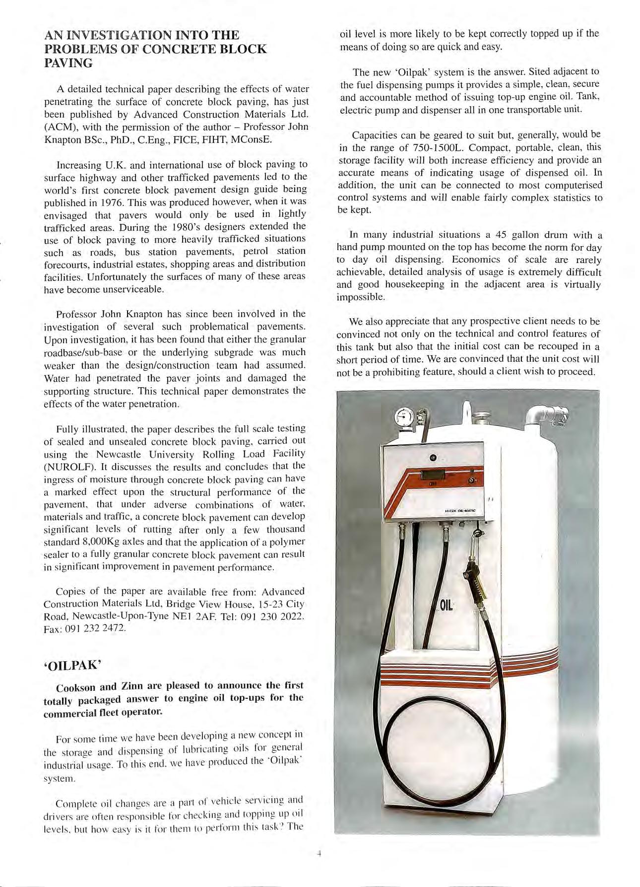
Cookson and Zinn are pleased to announce the first totally packaged answer to engine oil top-ups for the commercial fleet operator.
For some tim e we hav e bee n developing a new concept in th e storage a nd dispen s in g of lubri cat in g oil s for ge ne ra l indu s trial usage. To thi s end . w e ha ve produ ce d the ' Oilpak' s yste m.
Comp le te o il c hanges are a part of ve hic le se rvicing and dri ve rs are often res pon sib le fo r c hec king and toppin g up oil leve ls. but how easy is it fo r th e m to pe rform thi s ta s k 1 Th e
oil level is more likely to be kept conectly topped up if the means of doing so are quick and easy.
The new 'Oilpak ' system is the answer Sited adjacent to the fuel dispensing pumps it provides a simple, clean , sec ure and accountable method of issuing top-up engine oil. Tank , electric pump and dispenser all in one transportable unit.
Capacities can be geared to suit but, generally, would be in the range of 750- l 500L. Compact, portable, clean , this storage facility will both increase efficiency and provide an accurate means of indicating usage of dispensed oil. In addition, the unit can be connected to most computerised control systems and will enable fairly complex s tati stics to be kept.
In many industrial situations a 45 gallon drum with a hand pump mounted on the top has become the norm for day to day oil dispensing. Economics of scale are rarely achievable, detailed analysis of usage is extremely difficult and good housekeeping in the adjacent area is virtually impossible
We also appreciate that any prospective client need s to be convinced not only on the technical and control features of this tank but also that the initial cost can be recouped in a short period of time. We are convinced that the unit cost will not be a prohibiting feature, should a client wish to proceed.
A special new Oil Spill Response Kit suitable for dealing with emergency spill situations has been introduced by Furmanite Engineering Ltd as part of its extensive range of counter oil pollution equipment.
Consisting of an Absorbent Boom, 50 Absorbent Pads, a Surface Sampler and Filter Bucket, the Kit is aimed at providing a complete, efficient and ready to use solution to emergency spills. The "Super Sapper" Absorbent Boom and included in the Kit are the ideal choice for dealing with 011 chemical spills of any kind and are designed to provide safe, economical spill control and clean up of petroleum-based products both on land and water.
"Super Sapper" products offer a number of distinct advantages. Not only are they able to repel water while absorbincr 0 ·1 d 1 "' an petroleum-based products, but they are a so non-toxic, and will not rot, mould or mildew. They are also capable of absorbing up to 25 times their weight in petroleum prod d . ucts an remam durable and buoyant.
B Of the "Super Sapper" products in the Kit, the Flexible boom measures 3.04 metres (10 feet) in length and other 1oon;: can be easily linked together to form any required endgt · for use on water, they are easily deployed an retneved d · sat an will continue to float even after becoming urated with o'J Th p for 1 · e ads, on the other hand, can be used smaller leak d . . . up f s an spills m isolated areas, or for cleamng a ter larg ·11 they er spr s. They have the added advantage that can also be wrung out and re-used.
in Surface Sampler included in the Kit is ideal for use site remediatio · 1 · · · It en bi n an envrronmenta momtonng projects. a es sampl t b the 1 es o e extracted from the surface or wrthm 1qu1d in m · · sump onrtonng wells, settling ponds, tanks, barrels, s, etc.
Equipped . h SampJ , Wit 7.6 metres (25 feet) of lowering cord, the and cl:r tube will take an accurate cut of the liquid floatin ar Y mdicate the thickness of oils or other materials readilyg the surface. Colour and turbidity may also be c ecked in the field.
The final it · Passive . .em 111 the Kit, the Filter-Bucket, is a manual, hydrocarb sy.stem for separating lighter-than-water 1 d. any area th water. The system can be dep oye m system h . at 15 254mm (I O") in diameter or larger. The as a cap full it can be em of approximately 2 litres and when ptied manually and redeployed.
The Filter-B of is especially useful for retrieving small Industrial s Ydrocarbons from crroundwater wells, umps a d . "' electricity 't . . n settlmg ponds and because 1t uses no I IS Id I applicatioii ea for remote or potentially hazardous s.
For more inform· . contac1 the p d ation on the new Oil Spill Response Kit. ro LlCt Sale . o· . . . . . I .Id on Tel: (() 539 s 1v1s1on of Furmamte Engmeenng · · ) 729009 or Fax: (0539) 740295.
Over the last two years the retail petroleum industry has gone through something of a revolution with the advent of non-metallic tank and pipe materials, double-skin tanks, precision tank testing and various other environmental protection devices and systems.
Apart from the major oil companies, there must be a sizeable sector of the petrol storing fraternity, generally nonretail, that have yet to become fully attuned to the new order within the industry. Sectors I have in mind are car hire companies, transport companies, airfield and marina operators, utility and telecommunications companies plus of course the emergency services. There are also government and military installations which enjoy "Crown" immunity not even have to have a petrol licence or involve the hcensmg authorities at all in connection with their fuel installations.
Many organisations within this non-retail sector are of course fully aware of current thinking, indeed many are members of this Association but I feel there is a need for enlightenment in many and membership of this Association would seem to be a very good starting point.
Yours sincerely,
James L Luke JAMES LUKE & ASSOCIATESWiltshire Police have reported that a Dunclare quadro petrol pump was stolen from The Little Chef on the night of 2012 l December on the A303 Chicklade Hindon Salisbury, Wiltshire. ' '
The Quadro petrol pump model Q8 0088 Serial Number 90-5-13628 has not been found, petroleum inspectors and other members of the Association are asked to keep their eye ?ut for this dispenser. Wiltshire police PC 743 J Frost will be mterested to hear of anyone who knows about it or has been offered it for sale, he can be contacted on 0747 870203
The use of inadequately protected mild steel pipe for underground petroleum installations continued until relatively recently as accepted industry practice, confirmed by the old Home Office Model Code and, more recently HS(G)41. In America, where traditional installation standards had been far worse than those here in the UK, the Environmental Protection Agency, in an assessment of such installations, concluded that " ... piping is smaller and Jess sturdy than tanks. It is assembled in the field with numerous connections and usually installed near the surface. As a result piping suffers much more than tanks from the effects of installations mistakes, excessive smface loads, the stress of underground movement and corrosion."
Growing awareness of the potential for environmental damage as well as the safety hazards of even the smallest leak if undetected has been forced on all of us in the industry by legislation and by regulation backed by increasing financial penalties.
The oil industry, in its search for a better solution to the problem, took as a fundamental requirement that whatever material was used should not corrode; a wise precaution considering the environment in which it would be installed.
American industry confronted this problem and developed the grp pipe. It caught on rapidly here in the UK and there are now many installations in existence. Undoubtedly superior in many respects to corrodible steel, grp is not, however, the universal panacea. It does have some drawbacks which have become apparent in practice, mainly related to installation. It is up to two and a half times more expensive to install; it, too, relies on site joints which are vulnerable to di1t, grease, damp and low temperature all inherent features of a construction site and the integrity and effectiveness of which is largely dependant on the skill and care of the installer; it is vulnerable to mechanical damage, particularly during installation and it is time consuming to install. Even after installation it can be vulnerable to stresses transmitted directly from live wheel loads or as a result of movement caused by them.
In the early eighties Jan Ageheim, a Swedish oil company engineer, started to investigate the use of non metallic pipes for both forecomts and aircraft refuelling installations to overcome the disadvantages of steel whilst retaining the non-corrodible advantage of grp. As a result of his investigations he concluded that the only pipe which seemed to offer a satisfactory long term solution was polyethylene. As a result of his endeavours. UPP was born.
Polyethylenes, like epoxides and polyesters used in the manufacture of grp, are included in the generic word "plastics". Plastics are polymers all of which contain additives to make processing easier or to confer desirable properties or both. They can for convenience be divided into either thermoplastic or thermosetting materials.
Thermoplastics when heated will soften and may eventually become viscous liquids. On cooling, they stiffen and return to their former state. This process can be repeated indefinitely allowing scrap to be reprocessed. Polyethylene is a thermoplastic material.
Thermosetting materials will also soften on heating but continued heating causes adjacent molecules to become Jinked by strong chemical bonds to produce a material which is hard, rigid, insoluble and infusible. It is thermoset and cannot be reprocessed. Epoxides and polyesters are them1osetting materials.
Polyethylenes are tough at low temperature and typically have excellent chemical resistance and electrical insulation prope1ties. They can be extruded, blow moulded. rotationally moulded and injection moulded. They can be low. medium or high density. Low density is typically extremely tough, flexible and chemically resistant. High density is much stronger and stiffer and can be used at higher temperatures than low density, but is not as tough as low temperatures.
Polyethylene materials for pipe applications are known to be very tough. Their pe1formance permits them to operate at design stresses for up to and beyond 50 years service. To capitalise on these properties UPP has developed the polyethylene pipe system to the point where it can now meet the exacting requirements for use in petroleum installations. The pipe incorporates carbon as an additive to increase elect1ical conductivity so as to dissipate static before a dangerous charge can build up. The design also features a barrier layer to give increased resistance to stress cracking in long term service.
The features of polyethylene which make it partintlarly suitable for this application are:
highly resistant to attack by chemical agents and aggressive soils totally resistant to crnTosion excellent resistance to abrasion damage excellent aging properties giving a high safety factor
flexibility to absorb stresses from imposed loads or movement very low vulnerable to mechanical damage ability to be laid with easy bends to facilitate installation and reduce hydraulic losses in operation ability to be laid as a continuous run to eliminate or at least minimising site joints automated thermo-welding process ensuring perfect fusion joints irrespective of climatic conditions or operator skill installation time reduced by up to 50% compared with other systems smooth inside bore significantly reduces hydraulic friction loss

The complete process from materials input to packaging of the finished pipework is strictly controlled and documented. The raw material suppliers are ISO 9000 accredited and from the moment an order is placed with them strict quality assurance procedures are observed right through to delivery to the site.
The plant at UPP is state of the art and all the processes are automatically controlled and monitored by trained personnel. No less than 32 monitoring operations are carried out to check mix feed, barrier content feed, extrnder temperature, extruder output, diameter, thickness, circularity, cooling bath temperature, pipe marking, temperature and coiling speed and final cutting to length.
Final controls are imposed at the packing and storing stage and quality control operations form an integral part of the QA system. This ensures absolute consistency of product quality and all pipe is marked during manufacture to confirm compliance with specification. It is also marked with the month and year of manufacture so that any batch is fully traceable, even years after installation. For control purposes a sample is cut off the end of each pipe run and retained, fully identified and recorded
The granules are pumped to the loading hopper of the extrude· h · f 1 w ere they fall throuoh into the collecting zone 0 the s H . . "' . b · crew. ere the material 1s pre-compressed befo1e emg to the transforming zone where it is heated to a Plastic conct· .· d I · · then 1l1on, degassed and further heate . t is forced th h h · · I' ro.ug the twin headed extruder where t e mnei 1ne1, cont·11 · · · · t· d th h ' nmg a un1yue permeation burner. 1s e roug a i separate. hopper and extrusion fused to the inside of the Wall 111 the one operation. After this the pipe is drawn t iough th ·1· · ··d d " e ea 1brat1on device to secure the exact outs1 e iameter s· I . . h • · 11nu taneously the pipe is cooled after wh1c is passes throu I .·. . . g 1 a Water bath and then receives its approp11ate <1nd uniyue 'd · ... · · · d t. th 1 ent1hcat1on markmgs. By varymg the spee o e subsequent d.. ·h· 1awmg device the exact wall thickness is dc ieved with'111 the specified tolerances.
Finally th, · · . · . · · d 1 • e pipe is either coiled or cut to the des11e ength. The in · tl ·b · · 1· oie ex1 le smaller diameter pipes used or 'iUct1on lines · · 1· II . · aie supp 1ed to site in coil form to a ow continuous lengths to be installed.
The grade of UPP pipe manufactured specifically for use as pipe _features a special and unique internal limng contammg an mtegral barrier with the specific function of significantly reducing the permeation through the pipe wall. This pipe is designated UPP Extra and the word "Extra" appears next to the diameter and thickness markings on the pipe itself. Unlined pipe is suitable for vent, vapour and fill lines. The lining _is bright yel_Iow in colour contrasting with the black of the pipe and provides a smooth, low friction surface which reduces hydraulic loss in the pipe by up to 2'h times that for pipe. It is integral with the pipe so the of does not reduce its effectiveness and Its presence significantly increases the pipes resistance to stress cracking.
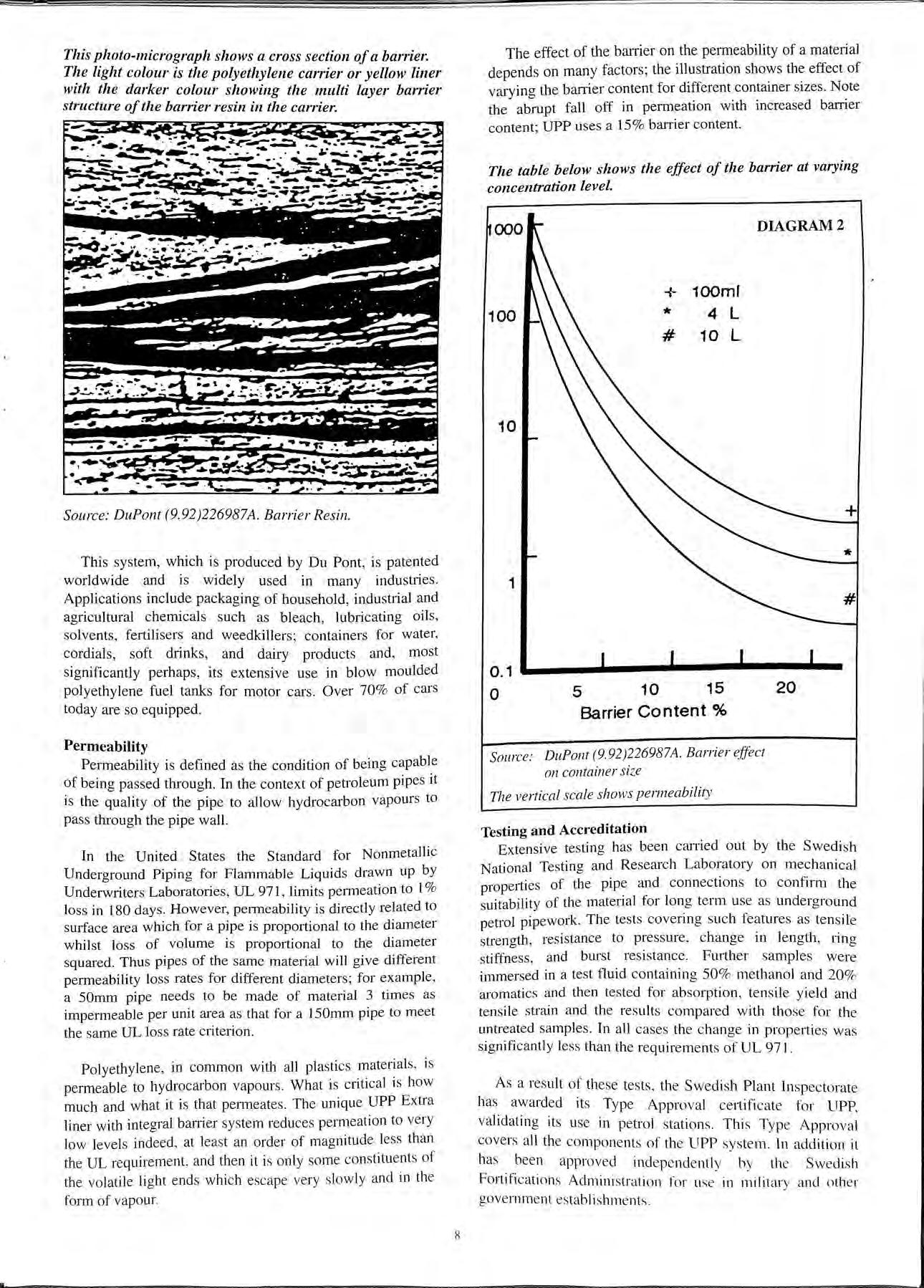
The barrier system consists of a specially modified resins blend. The resins are dry blended with a polyolefin resin and then extruded through the unique UPP twin head extruder. In this process. controlled mixing and shear allow the barrier resin to form numerous overlapping. discontinuous and elongated platelets within the structure of the parent material as can be seen in the photo-micrograph.
This system, which is produced by Du Pont , is patented worldwide and is widely used in many industries. Applications include packaging of household, industrial and agricultural chemicals such as bleach, lubricating oils , solvents, fertilisers and weedkillers; containers for water, cordials, soft drinks, and dairy products and , most significantly perhaps, its extensive use in blow moulded polyethylene fuel tanks for motor cars. Over 70 % of cars today are so equipped.
Permeability is defined as the condition of being capable of being passed through. In the context of petroleum pipes it is the quality of the pipe to allow hydrocarbon vapours to pass through the pipe wall.
In the United States the Standard for Nonmetallic Underground Piping for Flammable Liquids drawn up by Underw1iters Laboratories, UL 971, limits pem1eation to 1% loss in 180 days. However, perme ability is directly related to surface area which for a pipe is proportional to the diameter whilst loss of volume is proportional to the diameter squared. Thus pipes of the same material will give different permeability loss rates for different diameters; for example, a 50mm pipe needs to be made of mate1ial 3 times as impermeable per unit area as that for a l 50mm pipe to meet the same UL loss rate criterion.
Polyethylene , in common with all pla stic s mate1ial s, is permeable to hydrocarbon vapours What is c1iti c al is how much and what it is that permeates. The unique UPP Extra liner with integral banier system reduces permeation to very low levels indeed , at lea st an order of magnitude less than the UL requirement , and then it is o nly some constitu ents of the volatile li ght end s which esc ape ve ry s lo wly and in th e form of vapour.
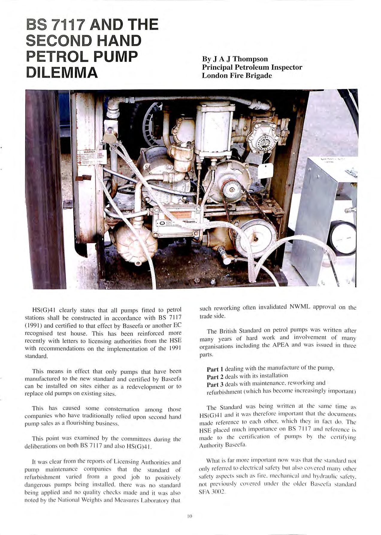
The effect of the barTier on the permeability of a material depends on many factors ; the illustration shows the effect of varying the barrier content for different container sizes Note the abrupt fall off in permeation with increased barrier content; UPP uses a 15% barrier content.
The table below shows the effect of the barrier at varying concentration level.
Barrier Content%
Source : DuPont (9 92)226987A. Barrie r effect on container si ze
The vertical scale shows permeabili ty
Extensive testing has been carried out by the Swedish National Testing and Research Laboratory on mechanical properties of the pipe and connections to confirm the suitability of the material for long term use as underground petrol pipework. The tests covering such features as tensile strength, resistance to pressure, change in length, ring stiffness , and burst resi stance. Further samples were immersed in a test fluid containing 50 % methanol and 20 % aromatic s and then tested for ab sorption , tensil e yield and tensile strain and th e results compared with those for th e untreated samples. In all c a se s the c hange in properti es wa s significantly less than the requirements of UL 971.
As a re s ult of th ese tes ts, th e Sw edi sh Plant Insp ectorate has awarded it s Type Approval certificat e for UPP validating its use in pe trol station s. Thi s Typ e Appro val covers all the c ompon e nt s of th e UPP syste m. In addition it ha s been approv ed ind e pe nd e ntl y b y th e S we di s h Fortification s Admini stration for us e in militar y and oth e r gov e rnm e nt es tablishm e nt s
This photo-micrograph shows a cross section of a barrie1: Tl!e light colour is the polyethylene carrier or yellow liner with the darker colour showing the multi layer barrier structure of the barrier resin in the carrie1: Source: DuPont (9.92)226987A. Barrier Resin.Whilst UPP may be new to the UK, its use is not new in Scandinavia In the ten years to 1991, over 300,000m have been installed in petrol stations constructed in Sweden, Norway and Denmark by, amongst others , Shell , Esso, BP, Texaco, Q8 and OK Petroleum. There have been no known failures or incidents recorded to date. In the UK, it is increasingly being used by oil companies as their engineers recognise its manifest advantage.
The use of UPP for new installations is obvious; it is equally appropriate however for work on exi sting sites. Becau se of its versatility and the availability of specially designed connectors for mating to galvanised steel pipework, it is ideal for use in alterations or additions to existing stations or, indeed, total replacement of defective steel pipe. And because it is quick , easy and cheap to in stall , the disruption to operating busine sses can be minimised and once installed there is the comfort and satisfaction of knowing that at leas t that part of the system will not fail in the lifetime of the site.

Engineers and enforcement authorities are required to make judgements as to the suitability of new products and developments which today assail them at an alarming a nd eve r increasing rate. A full under standing and assessment of
the likely performance of any new product is generally beyond the ability of many of those directly concerned with specifying and approving its use. In the case of pipework , the authoritie s can often be satisfied by the knowledge that the system is secondarily contained; if there is a failure, at least the leak is contained and the environment protected. For the engineer, however, this may not be enough. A failure is unacceptable as is the cost and disruption associated with replacing the failed element. Absolute confidence in the long term performance of the product itself is paramount.
It is therefore important that all non-metallic pipework systems be assessed independently using common standards, preferably based on European performance requirements, and the compliance ce1tified clearly for all to see by an accredited European test house.
UPP is the only system to have such accreditation in Europe. It was satisfying most if not all the requirements being imposed today long before the current environment considerations came to the fore. Its track record in Europe speaks for itself and the company's policy of continuous improvement of the product backed by heavy investment in R and D should ensure that UPP remains the most versatile and appropriate underground pipework system for petrol station forecourts.
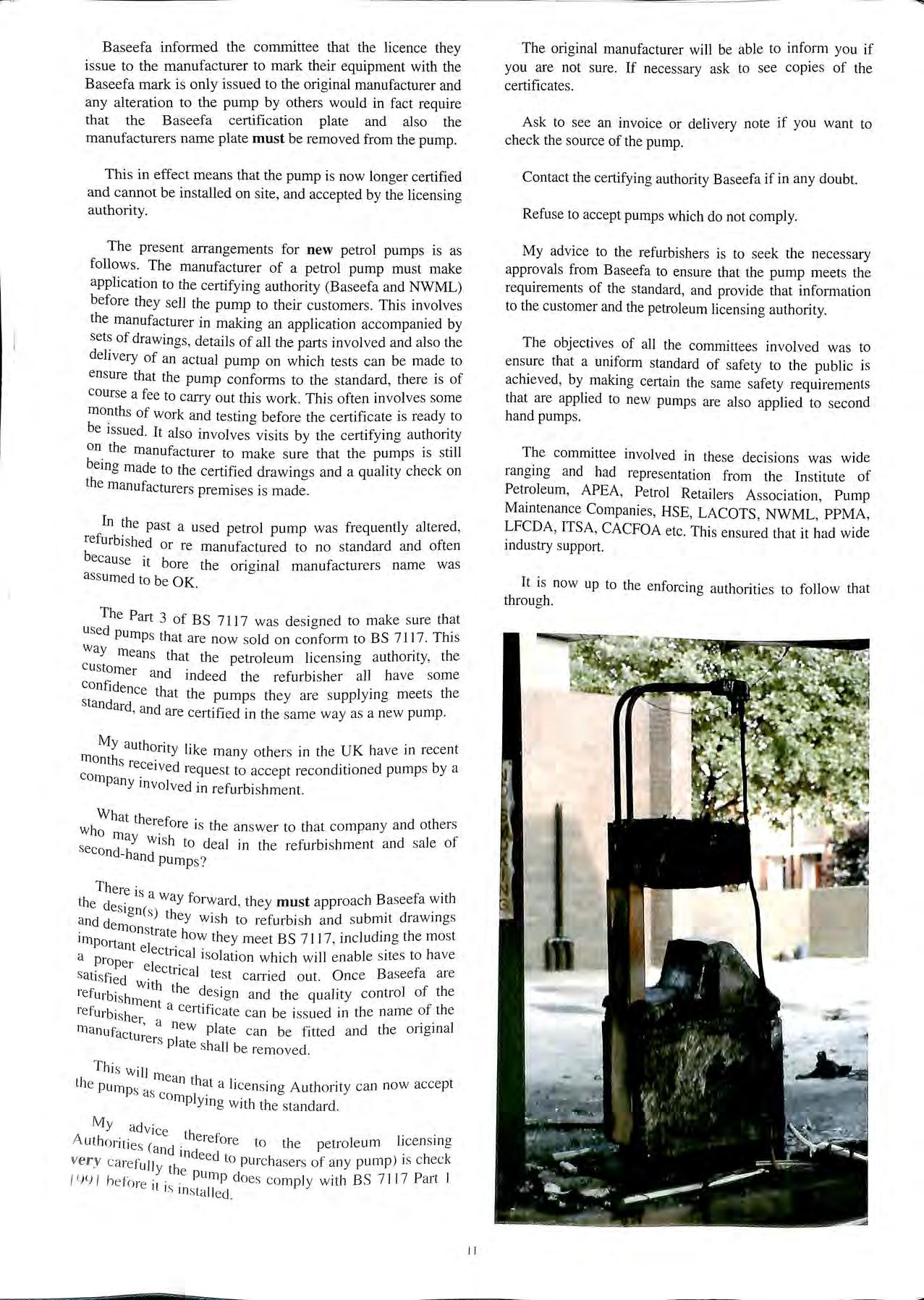
HS (G )4 l cl e arly state s th a t a ll pump s fitted to petrol s ta ti o ns sh a ll be constructe d in acco rd a nce with BS 7 11 7 ( 199 1) a nd ce rtified to th a t effec t b y B aseefa or an o th e r EC recog ni sed tes t hou se Thi s has b ee n re inforced m o re rece ntl y w ith le tters to lic e ns in g a utho1iti es from th e H SE w ith reco mm e nd a tion s on th e impl e m e nt a ti o n o f th e 199 1 s ta nd ard
Thi s m ea n s in effect th a t o nly pump s th a t ha ve bee n m a nu fact ure d to th e ne w s ta nd a rd a nd c e rtifi e d b y B asee fa ca n be in s ta ll e d on s ites e ith e r as a re d eve lopm e nt or to re pl ace o ld pump s on ex is tin g s ites.
Thi s ha s ca use d some co ns te rn a ti o n am o n cr th o se co mp a ni es w ho have trad iti o na ll y re li e d up o n ha nd p um p s a le s as a fl o uri s hin g bu s in ess
T hi s po int wa s exa min e d b y the c o mmitt ee s d urin o th e d e lib e rat io ns o n bot h BS 7 117 a nd a lso H S(G )4 1. "'
It wa s c le a r fr o m th e re po rt s of Li ce ns in g Auth o riti es a nd p um p m a in te na nce co m pa ni e s tha t t he s ta nd a rd o f re fu rb is hm e nt vari e d fro m a goo d job to po s iti ve ly d a nge ro us p u mp s be in g ins ta ll e d . t he re w a s no s tanda rd be in g a pp lie d a nd no qu a lity c hec ks m a d e a nd it wa s a lso no te d by the Nat io nal We ig h ts a nd Meas u res La borato ry tha t
suc h reworkin g ofte n inv a lid a te d NWML app ro va l o n th e trad e s id e
Th e Briti sh St a nd a rd o n pe trol pump s was w ritte n afte r m a ny years o f hard wo rk a nd in vo lve m e nt of m a n y o rga ni sa ti o ns in cl ud in g th e A P EA a nd wa s iss ue d in thre e pa rt s
Part I d ea lin g w ith the m a nu fac ture of th e pump Part 2 d ea ls w ith it s in sta ll a ti o n Part 3 de al s w ith m a int e na nc e, rew orkin g a nd re furbi shm e nt (w hi c h has bec o m e in c reas in g ly im p o rt a nt )
Th e S ta nd ard wa s be in g w ritte n a t th e sa m e tim e a s HS(G)4 l a nd it was th e re fo re imp o rta nt th a t th e do cu m e nt s m ad e re fe re nce to eac h o th e r. w hi c h th ey in fac t do T he HSE pl ac ed mu c h im po rt a nce o n BS 7 11 7 a nd re l'e re nce is mad e to the ce rt ifi ca t io n of p ump s b y th e cc rtil'y in g A uth or ity Basee fa
Wh a t is far m o re irn po rt a nt no w w as th a t th e s ta ndar d nut on ly re fe rred to e le ct ri c a l safe ty b ut a lso co\ e re cl m any u th c r s afet y as pec ts s uch as fi re m e ch a ni ca l a nd h ydra uli c .s a l'e ty not p rev io us ly cove re d und e r the o ld e r B a see fa s ta ncla rcl SFA 3002
Baseefa informed the committee that the licence they issue to the manufacturer to mark their equipment with the Baseefa mark is only issued to the original manufacturer and any alteration to the pump by others would in fac t require that the Baseefa certification plate and also the manufacturers name plate must be removed from the pump.
This in effect m eans that the pump is now longer certified and cannot be in stalled on si te , and accepted by the licensing autho rity.
The present arrangements for new petrol pumps is as follows. The manufacturer of a petrol pump must make application to the certifying authority (Baseefa and NWML) before they sell th e pump to th eir customers. Thi s involves the manufacturer in makin g an application accompanied by sets of drawin gs, details of all the parts involved and also the deli very of an actual pump on which te s ts can be mad e to en sure that the pump conforms to the standard , there is of course a fee to carry out thi s work Thi s often in vo lves so me month s of work and testin o- before the certificate is ready to be iss ued. It also in volves 0 visits b y the certifying authority on the manufacturer to make s ure that the pumps is still bein g made to the certified drawin gs and a quality check on the manufacturers premises is m ad e.
In the pas t a use d petrol pump was frequently altered, refurbished or re manufactured to no sta ndard and often because it bore the ori o-i nal manufacturers name was 0 as sumed to be OK.
The Part 3 of BS 7117 was d es io-ned to make sure that used pump s that are now so ld on to BS 7 11 7. This way means that the petroleum licen s in g a uthority, the cu stomer an d indeed th e refu rbi she r all h ave so me confide h · h nee t at th e pump s the y are supplym g meets t e standard d . , an are cert1f1ed m the same way as a new pump
My authority like many o thers in the U K have in recent month s re · d · · b · ce 1ve request to accept reco nd1t1oned pump s Y a company·in vo lved in refurbishment.
hWh at therefore is the an sw er to that co mpany and others w o ma Y w is h to deal in the refurbi s hment a nd sa le of second-hand pump s?
There is . h th e d . a way forward , the y must approach B aseefa w it and des ign(s) they w is h to refurbish a nd s ubmit drawings im how th ey meet BS 7 11 7 including the mos t P01tant e l · ' . a p ec t11c a l iso lati o n which will e na bl e s ites to have i ope r ele sati sf d . ctncal test carried o ut. Once Baseefa are le W1th th f h refurbi shm ent e design a nd the quahty o . t e refu rb· h a ce1t1f1cate ca n be iss ued Ill the na me of the is er a 1 manufa ' new plate ca n be fitted an d the ongrna cturers pi · ate s ha ll be re moved.
T hi s W1·1 l me·1n th th e pu rn c at a li ce nsin g A uth ority can now accep t ps as co rn I P Ymg w ith th e sta ndard
My adv ice h A uth o ritie ( .t e iefo re to the petroleum l1 cens 111 g s and incl d . h k ve rv ca ref 11 ee to purc hasers of a ny pump ) is c ec · u Y the / lJlJ / he for . . pump do es comp ly w it h BS 7 11 7 Part I e i.l is in s ta ll ed.
The original manufacturer will be abl e to inform you if you are not sure If necessary ask to see copies of the certificates.
Ask to see an invoice or deli very note if yo u want to check the source of the pump.
Contact the certifying authority Baseefa if in any doubt.
Refuse to accept pump s which do not comply.
My advice to the refurbishers is to see k the neces sary approvals from Baseefa to ensure that the pump meets the requirements of the standard , and provide that information to the customer and the petroleum licensing authority.
The obj ec tive s of all the committees involv e d was to en sure that a uniform standard of safety to th e public is achi eved, by makin g certain the same safety requirement s that are applied to new pumps are also applied to second hand pump s
The committee involved in th es e deci si ons was wide ranging and had representation from the In stitute of Pe troleum , APEA, Petrol Retail ers Association, Pump Maintenance Comp anies, HSE, LACOTS , NWML , PPMA , LFCDA, ITS A, CACFOA etc . Thi s ensured that it had wide indu stry s upport.
It is now up to the enforcing authorities to follow that through.
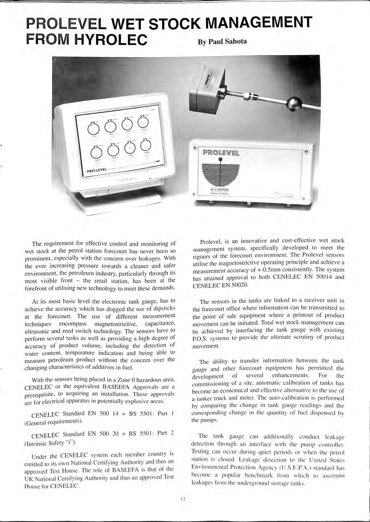
The requirement for effective control and monitorina of b wet stock at the petrol station forecourt has never been so prominent, especially with the· concern over leakages. With the ever increasing pressure towards a cleaner and safer environment, the petroleum industry, particularly tlu·ough its most visible front the retail station, has been at the forefront of utilising new technology to meet these demands.
At its most basic level the electronic tank gauge, has to achieve the accuracy which has dogged the use of dipsticks at the forecourt. The use of different measurement techniques encompass magnetostnct1ve , capacitance , ultrasonic and reed switch technology. The sensors have to perform several tasks as well as providing a high degree of accuracy of product volume , including the detection of water content, temperature indication and being able to measure petroleum product without the concern over the changing characteristics of additives in fuel.
With the sensors being placed in a Zone O hazardous area, CENELEC or the equivalent BASEEFA Approvals are a prerequisite , to acquiring an installation. These approvals are for electrical apparatus in potentially explosive areas.
CENELEC Standard EN 500 14 = BS 5501: Part I (General requirement s).
CENELEC Standard EN 500 20 = BS 550 I: Part 2 (Intrinsic Safety " i" ).
Under the CENELEC system e ach member country is entitled to it s own National Certifying Authority and thus an approved Te st Hou se The rol e of BASEEFA is that of th e UK National Certifying Authority and thu s an approved Tes t Hou se for CENELEC.
Prolevel, is an innovative and cost-effective wet stock management system , specifically developed to meet the rigours of the forecourt environment. The Prolevel sensors utilise the magnetostrictive operating principle and achieve a measurement accuracy of +-0.5mm consistently. The system has attained approval to both CENELEC EN 50014 and CENELEC EN 50020.
The sensors in the tanks are linked to a receiver unit in the forecourt office where information can be transmitted to the point of sale equipment where a printout of product movement can be initiated. Total wet stock management can be achieved by interfacing the tank gauge with existing P.0 S. system s to provide the ultimate scrutiny of movement.
The ability to transfer information betw een the tank ga uge and other forecourt equipment has permitted th e development of several enhancem e nts. For the commissioning of a site , automati c calibration of tanks has become an economical and effectiv e alternative to the u se of a tanker truck and meter. The auto-calibration is performed by comparing th e change in tank gauge readings and th e corre sponding chang e in th e quantity of fu e l dispen se d b y the pump s
Th e tank gaug e can additionall y conduct le akacr e det ection thro ug h an int e rfac e w ith the pump controll : r. Testing can o ccur during qui e t pe riod s or whe n th e pe trol s tation is clo se d. L e akag e de te ction to the U nit e d Stat es En vironm e ntal Prot ec tion A ge nc y (US .E .P. A .) standard ha s bec om e a popular be nchmark from w hich to asc e rtain le akag es from th e und e rg round storag e ta nk s
Temperature compensation raises seve ral issues. For effective leakage detection the temperature of the fuel in the tank is required to gain a preci se reconciliation of product movement. The use of standardised litres at a temperature of 15 °C, protects all parties from the problems which can occur from receiving product of differing temperatures.
Furthermore , accurate tank gaugin g wi th temperature compen sa tion pro vide s an effective me thod of recordin g th e amo unt of product de li vered at a site and hence play s a n esse ntial role in th e deve lop me nt of Dri ve r Controlled Delivery link s
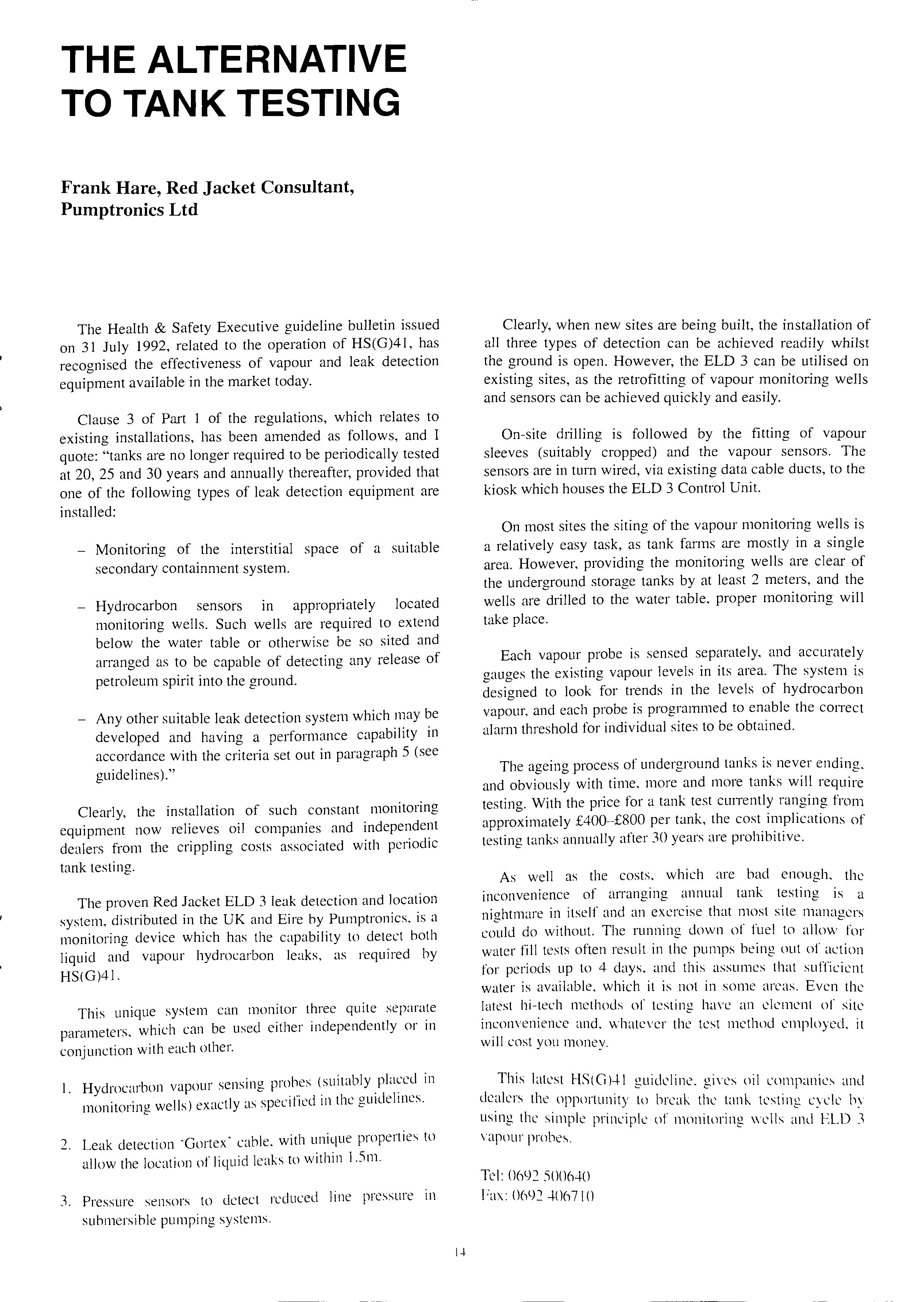
The Prolevel sys tem incorp ora tes e ith er a di splay unit or a dedicated computer. From the PC , the colour grap hic s
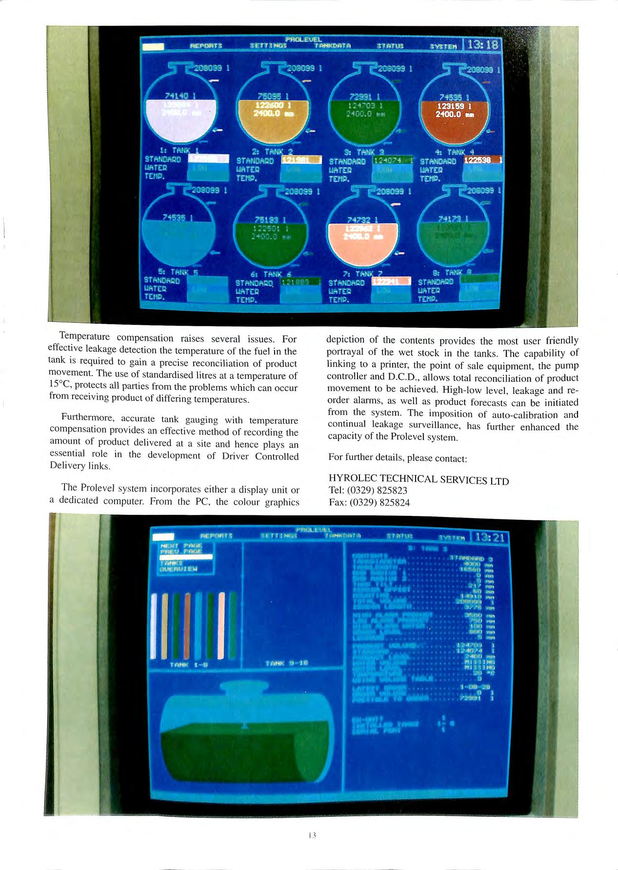
depiction of the contents provides the most use r friendly portrayal of the wet stock in the tanks. The capability of linking to a printer, the point of sale equipment , the pump co ntroller and D.C.D., allows total reconciliation of product movement to be achieved . High-low level, leakage a nd re order alarms, as well as product forecasts can be initi a ted from the system. The impos ition of auto-calibration a nd co ntinual leakage s ur ve ill ance , has further enhanced the capacity of the Prol evel sys te m.
For further detail s, please co nt act:
HYROLEC TECHNICAL SERVICES LTD
Tel: (0329) 825823 Fax: (0329) 825824
The Health & Safety Executive guideline bulletin issued on 31 July 1992, related to the operation of HS(G)4 l, has recognised the effectiveness of vapour and leak detection equipment available in the market today.
Clause 3 of Part 1 of the regulations, which relates to existing installations, has been amended as follows, and I quote: "tanks are no longer required to be periodically tested at 20, 25 and 30 years and annually thereafter, provided that one of the following types of leak detection equipment are installed:
Monitoring of the interstitial space of a suitable secondary containment system.
Hydrocarbon sensors in appropriately located monitoring wells. Such wells are required to extend below the water table or otherwise be so sited and arranged as to be capable of detecting any release of petroleum spirit into the ground.
Any other suitable leak detection system which may be developed and having a pe1formance capability in accordance with the criteria set out in paragraph S (see guidelines)."
Clearly, the installation of such constant monitoring equipment now relieves oil companies and independent dealers from the crippling costs associated with periodic tank testing.
The proven Red Jacket ELD 3 leak detection and location system, distributed in the UK and Eire hy Pumptronics. is a monitoring device which has the capability to detect both liquid and vapour hydrocarbon leaks, as required by HS(G)41.
This unique system can monitor three quite separate parameters. which can be used either independently or in conjunction with each other.
1. Hydrocarbon vapour sensing probes (suitably in monitoring wells) exactly as specified in the gu1del111es.
2. Leak detection ·Gortex · cable. with unique properties to allow the location of liquid leaks to within I ..Sm.
3. Pressure sensors to detect reduced line pressure 111 submersible pumping systems.
Clearly, when new sites are being built, the installation of all three types of detection can be achieved readily whilst the ground is open. However, the ELD 3 can be utilised on existing sites, as the retrofitting of vapour monitoring wells and sensors can be achieved quickly and easily.
On-site d1illing is followed by the fitting of vapour sleeves (suitably cropped) and the vapour sensors. The sensors are in turn wired, via existing data cable ducts, to the kiosk which houses the ELD 3 Control Unit.
On most sites the siting of the vapour monitoring wells is a relatively easy task, as tank farms are mostly in a single area. However. providing the monitoring wells are clear of the underground storage tanks by at least 2 meters, and the wells are drilled to the water table, proper monitoring will take place.
Each vapour probe is sensed separately, and accurately gauges the existing vapour levels in its area. The system is designed to look for trends in the levels of hydrocarbon vapour, and each probe is programmed to enable the coITect alarm threshold for individual sites to be obtained.
The ageing process of underground tanks is never ending. and obviously with time. more and more tanks will require testing. With the price for a tank test cuITently ranging from approximately £400-£800 per tank, the cost implications of testing tanks annually after 30 years are prohibitive.
As well as the costs, which are bad enough. the inconvenience of arranging annual tank testing is a nightmare in itself and an exercise that most site managers could do without. The running down or fuel (O allow for water fill tests often result in the pumps being out of action for periods up to 4 days. and this assumes that sufficient water is available. which it is not in some areas. Even the latest hi-tech methods or testing have an ekmcnl or site inconvenience and. whatever the test method employed. it will cost you money.
This latest HS(GJ-1-1 guideline. gi\es oil companies and dealers the opportunity lo break the tank testinl'. cvclc h using the simple principle of monitoring wells ELD :i vapour probt's.
Tel: 0692 .'i006-l-O Fax: 069 2 -l-06 7 1()
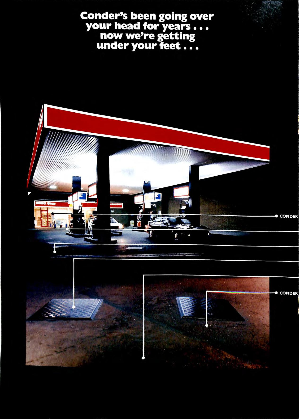
Conder's aim has always been to develop better products and building method sto accelerate the construction process the sooner your forecourt is up and running, the sooner your return on in vestment. 30 years ago w e introduced the prefabricated Canopy, later the GRP Interceptor and most recently the revolutionary Fibrelite A ccess Covers with their light weight, you don't need a 'feat' of strength to lift them. Now, Conder can offer a complete range of ready made products designed specifically for the forecourt.
Modular Convenience Store and Car Wash buildings delivered to site ready wired, plumbed and fitted out for rapid assembly; Access Chambers to contain possible fuel spi llage and keep out sub-soil water; Silt Traps to avoid drain blockages and last, but not least, Pump Island Barriers all from one source and delivered to site.

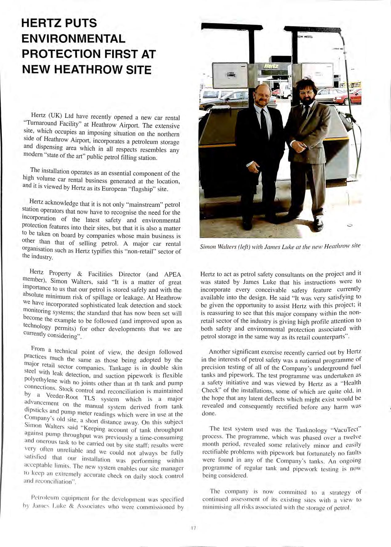
Hertz (UK) Ltd have recently opened a new car rental "Turnaround Facility" at Heathrow Airport. The extensive which occupies an imposing situation on the northern side of Heathrow Airpo11, incorporates a petroleum storaae and dispensing area which in all respects resembles modem "state of the art" public petrol filling station.
The installation operates as an essential component of the high volume car rental business <>enerated at the location and it is viewed by Hertz as its "flag ship" site. '
J:Iertz acknowledge that it is not only "mainstream" petrol station operators that now have to recoanise the need for the b incorporation of the latest safety and environmental protection feature s into their sites , but that it is also a matter to be taken on board by companies whose main business is other than that of selling petrol. A major car rental organi sation such a s Hertz typifie s thi s " non-retail " sector of the indu stry.
Hertz Property & Facilities Director (and APEA member), Simon Walters, s aid " It is a matter of great importance to us that our petrol is stored safely and with the ab solute minimum 1isk of spillage or leakage. At Heathrow we hav e incorporated sophi sticated leak detection and stock monitoring sy stems; the s tandard that has now been set will become the example to be followed (and impro ved upon as technolo gy permits) for other de velopments that we are currentl y con sidering" .
Fro m a tec hnical point of vie w, the de s ig n followed prac ti ce s 1 h 11u c the sa m e a s tho se bem g adopted by the ma.i o r retail sector comp a nie s . Ta nk a ge is in double skin stee l w ith le k d 1 a etect1on , and s uction pipe w ork 1s fle x 1b e pol ye th ylene · h · Wit no JOmt s o th e r than at th ta nk and pump co nn e c ti o ns St k b · o c c ontro l a nd re c onc1hat1on 1s mamt a med y a Ve ed e r-Root TLS d sy ste m whi c h 1s a m ajor a va nce me nt 0 1 th d . 1 e m a nual s yste m deri ve d from tank 1p st1 c ks and pump me te t re adm gs w hi c h we re 111 use a t the Co mp a ny s o ld s 1.te · I 1 · b. · , a s 1o rt c 1sta nc e a way. On thi s s u JeC t S im o n Wa lte rs ·d " K · . · sa t ee pm g acco unt of ta nk throu g hput aga in st ]Jump throu <> h t b pu w as pre vio usly a t im e -c o ns umm g a nd o ne rou s tas k to b · .· · e c at 1 te d out by s ite staff re s ult s w e re ve ry ft 1· b ' 0 e n unre ta le a nd we co uld not a lways be full y s a t1 s f1e d tha t 0 111· 111 st 1Jl ·it· f · · I · · ' , 10 11 wa s pe 1 o rm111 g w it 1111 acce p t· bi I · ·· TI · · a e 1m1t s 1e new sys te m e na bl es o ur s it e m a nage r to ke e p a n ex tre me ly ac c urate c hec k o n d a il y sto c k c o ntrol a ncl re co nc iliati o n"
Pe tro le u m e quipm e nt fo r th e deve lo pm e nt was spec ifi e d b y Luk e & A s soc iates w ho we re co mmi ss io ne d by
Hertz to act a s petrol safety consultants on the project and it was stated by James Luke that his instruction s were to incorporate every conceivable safety feature currently available into the design. He said "It was very sa tisfyin g to be given the opportunity to a s sist Hertz with this project ; it is reassuring to see that this major company within the nonretail sector of the industry is givin g hi<>h profil e attention to both safety and environmental a ss ociated with petrol storage in the same way as its retail counterparts " ·
Another s ignificant exerc ise recently carried out by Hertz in the interests of pe trol safety was a national programme of preci s ion testing of all of the Company ' s underground fuel ta nk s and pipework. The test programme was undertak e n as a s afe ty initiative and wa s viewed by Hertz a s a " H ea lth Check" of the in stallation s , some of which are quite old , in the hop e that an y la tent d e flect s whi c h mi<>ht e x ist would be b reveal ed and con se quently re ctified be fore any harm w as don e
Th e tes t sys tem used wa s th e Ta nknology " VacuTec t" proc e ss Th e prog ramm e , w hich wa s pha sed ove r a tw e lve month pe riod , re ve aled som e relativ e ly min o r and eas ily rectifi abl e probl e ms with pip ewo rk but fortun a te ly no fault s we re found in a ny of th e Comp a ny ' s tank s An on g oin g pro g ramm e of reg ular tank a nd pip ewo rk tes tin g is now be in g co ns id e re d.
Th e co mp a ny is now co mmitte d to a strategy of c ontinu e d a sse ss me nt of it s e x istin g s it es with a view to minimi s in g a ll ri s ks a ss oc ia te d w ith th e s to rag e o f pe trol.

Th e re are te ns of thou s and s of und erground storage ta nk s in the UK , which conta in pe tro leum or other h azardou s liquid s a nd c hemical s
Th ese can present tw o probl e m s, LEAKAGE a nd S PILLA GE. This paper res trict s th e topic to Spill age prev e ntion.
Th e re a re several Nation a l and Int e rnational bodi es , o r A cre nc ies who a re con ce rn e d with the co ntrol of su c h "' probl e m s , but to date th e re d oes not appe ar to b e a harm o ni sed Internation al sp ec ifi cati o n o r leg islation. It is th e refo re left up to eac h area li ce ns in g officer to exe rcise p owe rs av ailable to him to require th e op e rator of s ites co nt a inin g underg round s torage ta nks to equip them with s uit a bl e de v ice s to prev e nt ove rfi llin g
Wh e re there are hum a n b e in gs involved , if th e imp ro b a bl e c an ha ppen, it will!
Wh e re th e re are failur e m o des in e quipm e nt , th ey w ill fa il'
Wh e n a n incident o ccurs, w ho e ns ure s th a t it is re ported ? It is ofte n in the self interes t of th e pe rso n/p e rson s in vo lved to not re po rt it , becau se of th e p ossi bl e co nsequ e nces. It is the refo re ass umed that th e re a re a g rea t m a ny more in c id e nts th a n a re ac tually rec ord ed d ue to th e under re portin g s yndro m e.
In the U S A it is es tim a ted th a t 50% of th e popul a ti o n uses ground wa te r as a s ource of drin k in g wa te r, a nd it is o nl y w he n a maj o r di sas te r occ urs, th at we a re awa ke ned fro m o ur pres um ed sa fe ty a nd sec urity fro m s uc h mi s ha ps We have face d th e re pe rc uss io ns of s pillage , so me tim es d a nge ro us p ro b a bl y ve ry cos tly, a lways a vo ida bl e in h111 dsi g ht a nd we will co nt inu e to face th ese d a nge rs until s u_c h tim e as to ta lly sec ure sy ste m s a re eco no mi ca ll y a vail abl e a nd ma nd a ted to be in s tall e d.
Co nfinin g th e topi c to ove 1f ill preve nti o n of und e rgro un d ta nks a t petro le um fo reco urt s ites, th e n thi s pa pe r w ill .11 t a te th a t s uc h a tota ll y sec ure sy s te m , w hi c h is I US I , f" d cl nl ca ll y v ia bl e ea s1 y re tro 1tte to mo s t uncl e rgro un ith o ut th e nee d to e m pty or dega s 1s now ava I! a bl e , ta nk s w . 1 d . 1 1 1 t d d tes ted a nd be mg 1tte 111 a rge sea e a pp 1ca ion s m tn e a n E e w ith trial s o ngo mg 111 th e UK urop ,
What is m eant
F irst ly we mu s t cla rify a sma ll po in t o n det1111 t1o n Man y I Se th e wo rd o ve rs pill preve nt ion 1 prele r to use th e pe op e LL · wo rd 0F erfifl Pre ven1io11 If yo u d o no t o ve rf ill. yo u w ill no t s p ill.
Primary ov e rfill preve nti o n equipment 111 pe t ro le um te rm s us uall y includes s uc h it e m s as ga ug in g , m ete rin g o r oth e r produ c t lev el indi cat io n o r co ntrol. Th ese .eq u ipm e n ts have bee n we ll se lec ted ove r th e ye ars to p rov id e 111 m o st in sta nce s a ve ry acce pt abl e leve l of con trol fo r th e co n ect fillin g o r mo nitorin g of prod u c t leve l in tank s
Howeve r, as s ta ted prev io u s ly, a ny s uc h sy s te m ca n fai l, o r e mit erron eo us dat a, a nd mo st imp o rt a ntl y, eve n th o u g h co mpute rs are use d mo re a nd m o re , th e in fo rm a ti o n put 1n us ua ll y has as it s so urce of or ig in , a hum a n o p era to r.
I ha ve heard it sa id a nd see n it written th a t th oro u g h a nd co rrec t tra inin g of o pera to rs is th e bes t fo rm of co n tro l. b ut we still have a ir, t ra in , shi p a nd ve hicl e d isa ste rs. e ven th oug h th ey ai·e ofte n co n tro ll e d by th e m os t hi g hl y sk ill e d a nd tra in ed peo pl e. I ag ree tra inin g is v it a ll y im po rt a nt , b u t 100% d isc iplin e is im po ss ib le to a ppl y. a nd s ho rt c uts. e1rn rs. lac k of v ig il a nce . di s trac ti o n s o r co mpl ace ncy w ill occ ur. a nd w hen thi s is co m b in ed w ith th e pot e nt ia l fo r eq ui p m e nt e r ro r o r fa ilure. in c id e nt s wi ll oc c ur
Secondary o verfi II p re ve nti o n sys te m s a re to b e co ns id e red th e las t lin e o f defe nc e in p re ve nt in g a sp ill. If a ll th e ro utin e di sc ip lin es a re fo ll ow e d. a nd all o th e r sy s te ms fun c ti o n c o rrec tl y. the n s uc h sy s te m s s ho ul d neve r no rm a ll y be bro ug ht in into o pe ra ti o n
By the time such equipment use is initiated, it can be said that the incident has already occurred, and in short, the secondary overfill prevention equipment has performed its prime function Prevention of a possible catastrophic spill.
As the last line of defence , any overfill prevention system MUST operate when it has to. How can this be achieved?
The answer is DYNAMIC SELF CHECKINGR towards achieving a FAIL SAFE circuit design concept.
The most apt description I have yet come across, is to compare self checking to the human heart beat. Whilst you are inactive, such as in sleeping, then you rely upon your heart to be quietly ticking away, so that when you wake up , you have nothing to check, no controls to initiate, you know that you will function You have not failed whilst inactive.
Any system that does not employ a complete self testing of all circuit functions cannot guarantee operation when that possible vital moment is reached, and additionally if operation cannot be guaranteed, the system must fail safe, and continuation of loading or unloading must be halted instantly.
SCULLY invented the DYNAMIC SELF CHECKINGR, concept in order to ensure that the secondary overfill prevention system must be incapable of failure , in order to satisfy the objectives of preventing the accident from progressing to it s potentially cata strophic end
It is the design properties of a system which will PREVENT ITS FAILURE FROM EITHER CAUSING OR ALLOWING INJURY TO PERSONS OR SIGNIFICANT DAMAGE TO PROPERTY
The conclusion we reach abo ut secondary ove1fill prevention s ystem s is that to trul y perform their function , they mu st be capable of neither failing during idle periods without a nnouncing that they are not ready to perform , nor of failing during a fuelling op e ration w ithout a larming , and ini t ia t ing a n in s tantaneou s s hutd ow n of the load in g/unloading proce ss

FAIL SAFE when app li e d to O v e1fill prevention e quipm e nt , re quires that a sys tem doe s not a llow it s own fa ilures to rend e r it se lf unable to detect liquid whil st indi cati ng a "No rmal " o r " Safe " cond iti o n.
Thi s co nce pt is fundam e nt a l to the und e rstanding of th e re maind e r o f thi s pap e r a nd is wo rth y of s ummary.
* A d es ig n appro ac h wh ic h o ffe rs n1axi1nun1 s afe ty op e rat io n
'! Sys te m c annot fa il leav in g yo u unprotec te d a s in c o n ve nt io nal ove rfi II sys te ms
'" C os t e ffec t ive- ac hi eves t he ultimate in s afety w ith o ut the ex p e nse of fre qu e nt manual c hecks o r maint e na nce
; Ba se d o n DYNAM IC SELF C H EC KI NGH
* Causes the monitoring system to rapidly switch between the normal condition and fault condition
* Monitor circuit "looks for" this dynamic oscillating signal, interpreting its absence as a fault (OVERFILL)
* Result is, any faults in the sensors, control monitor, cable, plug and socket pin contamination or wear, will be interpreted as a fault, therefore an overfill condition, and shutdown.
"'
continually tests the loop between the control monitor and the sensors.
What is the situation today? From our knowledge of UK petroleum retail sites, there are difference s of opinions be tween the multitude of licensing authorities. Some do not require any ove1fill prevention sys tems at all, whil s t others in s ist upon it. Some will restrict the number of hoses allowed_ to be di sc harged from tanker to underground tanks to _one, 1f mech anical float s are fitted , and vapour balancing 1s mcorporated.
Options Available 1. High lev e l alarm as part of a tank ga ug ing sys tem
Mechanical float system s
Retail s ite powered system co ntrollin o the vehicle off b lo ad mg 4. Road tanker controlled syste m , s hutting off th e vehicl e unloadin g.
l Hig h level alarm
* Doe s not pro vid e a se lf c hec king fail sa fe sys te m. and fail s to co nform to the require me nt s of kee ping Overfi ll preve ntion e quipm e nt ind e pe nd e nt of other sys te ms s uc h as ta nk ga ug in g
* Measurement of liquid volume is the primary function of a gauging system. The emphasis of the design is on accuracy of measurement and not on fail safe operation. As the systems do not CONTROL the flow of hazardous liquids they do not employ failsafe design concepts. The use of a high level alarm output to signify a possible overfill, does not offer the safety level required.
2 Mechanical float systems
* Have moving parts, and are known to have reliability problems.
* Mechanical devices can fail in an unsafe mode
* The mechanical in-tank fill pipe float restricts product flow
* Mechanical devices have no means of self testino their b operat10n. It is even difficult to conduct a manual test on them.
* Hose drain down is severely restricted after a mechanical float shuts off the flow.
* There is no automatic indication to the driver that an overfill has occurred
* Me_chanical devices with moving parts require regular mamtenance
* Mechanical Floats are expensive to fit into "live" tanks
* Can cause problems with pressure build up on vapour balanced sites
* Mechanical devices have no capability to record an overfill occurrence
3 Retail site controlled systems
* Retail site powered systems require AC mains supply
* One controller per retail site is required, therefore not cost effective compared to vehicle mounted systems.
* A controller failure puts the station out of action for unloading
* More complicated to feed back information to an On Truck Computer
* If a two · nu wire sensor system is employed, then the mber of underground tanks that can be accommodated · · is a maximum of eight with one controller
* A second cont· II · · 1o e1 would be reqmred for more than eight underground tanks
':' Limited i 1 b·i· 1 capa 1 Hy to support additional features such as ··w, 1 • h. · et eg sensor'. and "Cross over prevention" w ich should he vehicle controlled
* Expensive valves w1"th bl•'ed h . b mec amsms may e required at tl · le service station
· (Jther 1neth d · · 0 s may require pneumatic connections het ween the i· 't· ·1 e di site and the road tanker
4 Road Tank v · er eh1cle Controlled System
I Im, svstem · LI • • is le one which employs the state oJ the art 11·1 h1Hil(lu\. over. 1 · a I the disadvantages oJ the /lit < 111-.h Ill t" en ioned systems. and is the most 111111' 1' i;dl\ viable yet providing unquestionahle the 111:.:lw· i , /, !..!lt't • ,/ '>al"cty.
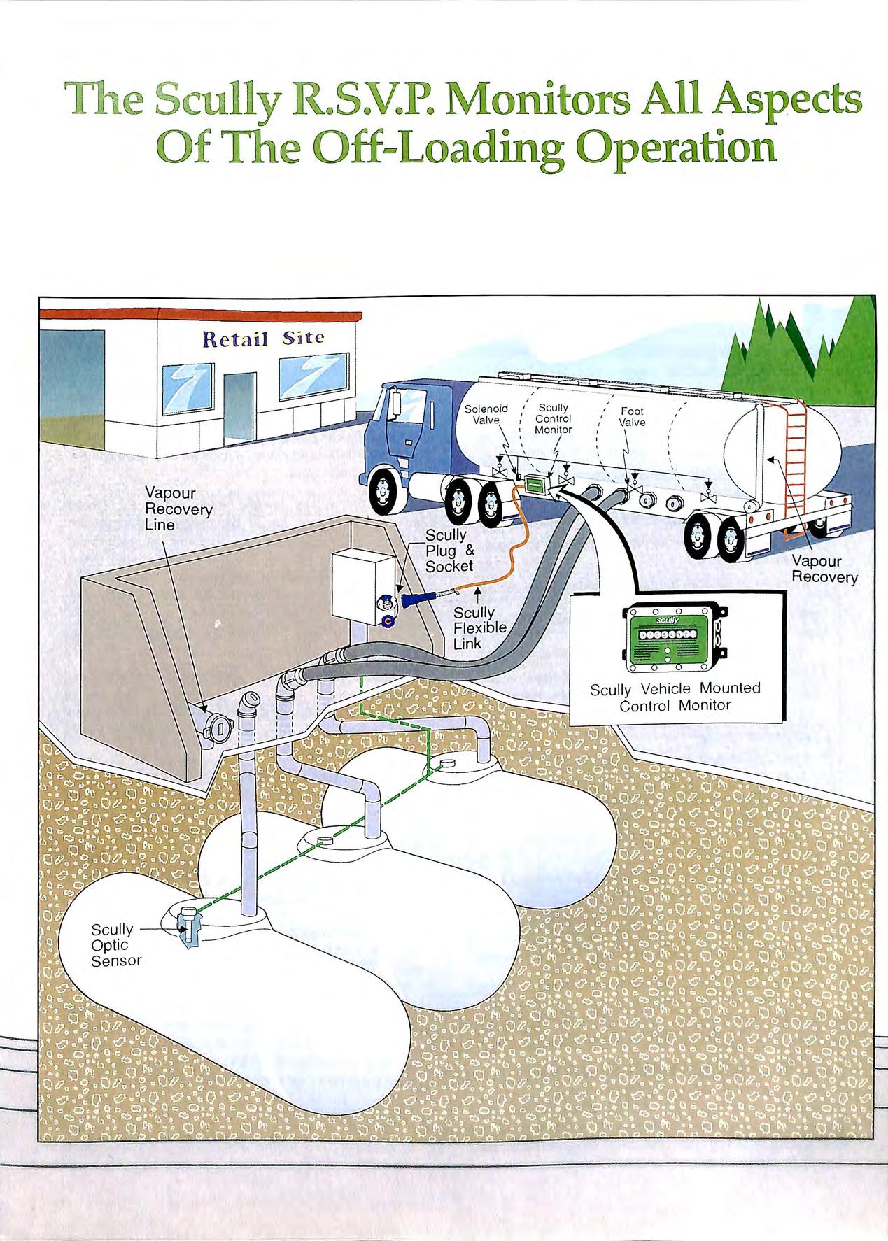
The RSVP system offers a vehicle controlled overfill prevention at the retail site. The system employs an electronic control monitor which is mounted on the road tanker, and controls the pneumatic valves on the trailer to stop unloading if an overfill is detected by any one of the Optic sensors located in the retail site underground tanks.
The system employs the Dynamic Self-TestR concept to automatically and continuously test the system at least 30 times every second. Under this concept, a dynamic pulsing signal is employed to simulate the "Wet" and "Dry" condition on the sensors, in order to continually test their ability to respond to an overfill incident.
The Dynamic signal also checks for any wiring faults, or failures in the sensors or control monitor circuitry. The instant an overfill is detected, or a fault occurs, or even deliberate tampering with the equipment to try to cheat it, the Dynamic Self-TestR circuit signals for a shutdown of the fuel unloading operation.
All of the valves on the road tanker are closed simultaneously if any one of the underground tanks are overfilled. Various options are available to enable the continuation of off loading into other underground tanks, should that be the wish of the operating company. The system is also Foolproof should the driver attempt (by mistake) to try and put more product into the already overfilled tank, with the RSVP system, it is not possible.
The RSVP control unit is housed in a compact metal enclosure, and as it weighs less than I .Skg, it is insignificant. It is powered by the vehicle's 24v battery, and supplied intrinsically safe power to the optic sensors in the retail site underground tanks.
The vehicle control monitor, provides an output relay which is used to energise a solenoid valve that controls the pneumatic valves on the vehicle. The solenoid is only energised when the sensors in the underground tanks are dry. A failsafe operation therefore is again assured as any fault, or overfill condition de-energises the solenoid, this exhausts air from the pressurised foot valve line, and automatically closes them.
An optic sensor is mounted in each tank, usually through a spare 2" BSP access in the manlid. Other mounting options are available.
The sensors arc adjusted in length to the required sensing level. which is normally 25mm above the maximum ullage level. The sensors are wired back through ducting to either a Scully socket at the offset fill line. or a socket in the direct fill well. Once fitted. the sensors require NO maintenance.
* Dynamic Self TestR The proven technique for continuous self testing of the system for maximum safety in operation.
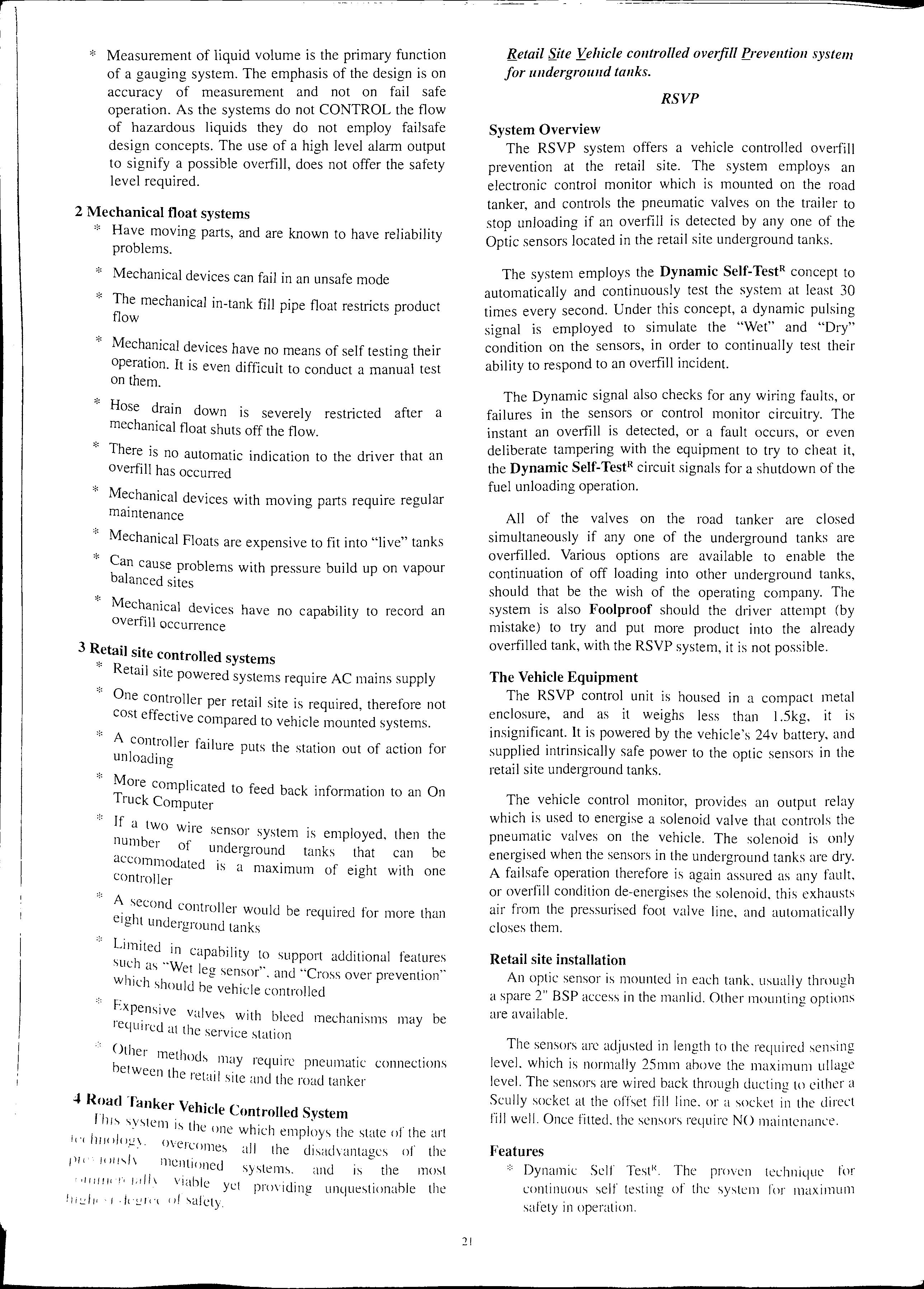
* The tanker mounted electronic control monitor directly controls the unloading process, and closes the valves on the vehicle if an overfill is detected
* The vehicle mounted controller is maintenance free
* Employs "five wire optic" sensors permanently mounted at the correct level in each retail site underground tank
* The sensors are maintenance free
* Only 5 wires are required between the road tanker and the retail site socket regardless of the number of underground tanks
* The truck to retail site connection is made via the proven plug and socket method, as universally used when loading the tanker at a gantry in a terminal
* Upon connection, there is an instant permit to unload, and there is no warning up time as there is with thermistor sensors.
* There is no restriction to flow, and instant drain down of hose into the remaining ullage in the case of an overfill.
* The vehicle control monitor incorporates a diagnostic display of LED's which clearly identifies which tank is overfilled. It also provides a positive indication when all sensors are dry, through a scanning display of Red
LED's. A green LED indicates a PERMIT to unload, and an additional yellow LED confirms that the battery power is applied to the controller.
* The vehicle controller consumer very little power due to the five wire optic system employed
* The controller and sensors are certified to BASEEFA/CENELEC standards
* The system has successfully undergone exhaustive field trials, and is now being used in Europe as the preferred system
* The RSVP system has additional relay outputs to provide a signal to an On Truck Computer that an overfill has occurred
* The system can be used in conjunction with vapour collection, and a simple addition will ensure that the vapour recovery hose is connected to the retail site before off loading can commence
* Using the RSVP eliminates the need for spill containment manholes
* Provides overfill indication to the driver
* Offers future expansion capability for electronic signalling between the vehicle, retail site and OTC system
th · d m l r e environment has produced more an ore eg1slaf Petrol f ion to protect us from pollution and danger. orecourts · · f th m ·t now have stnct regulations or e oni onng a d E n storage of wet stock The Health and Safety xecutive HS(G) 4 · local 1 1 gu1delmes are rigorously enforced by icenc1ng auth records of all onties. Each site must keep proper can b d wet stock movements so that losses or leakage 0 e etected before potentially hazardous situations can ccur.
Failure of a · fine site to maintain these records could mean a or even cl . manually b t os.ure. In. most sites the monitoring 1s done storage t J aking daily readings from all underground product d:li: and pumps. Records are also kept of any the re] enes. Forms are then filled in by hand before evant perce t ki average s 1 n ages and continuous weekly wor ng are I time and ff nous Y calculated. This takes con siderable help at he odrt and if a discrepancy is detected , there is little an to p· Con sid . bi mpomt the real source of the problem . e1a y mor ca lculat· e time can be wasted while previous ion s are eh k ec ed and rechecked for en-ors
R eco nciliation rep orted t h . problem s over a given limit must be 0 t e hcen · be fo und th . Ci11g authority and , unle ss the reason can , e site may b I ak place It 1·s th e c osed while 111ve st1gat1on s t e · erefore · I co rrect ly e a! Vita for forecourts to keep ac curate , CONSIDE R c ul a te d record s BUT ALL THIS TAKES
A fully automa te d . . P UITT JJ c o nti· 11 site With state o f-the -art tank gauges , o er and b th e u lti mat wet. stock management s ystem may e e a nswe r h' · · h 1-1 S I ( · J4 I T h 111 ac 1ev mg conforman ce wit · 1 ese sys t I J I ems are not o nly cost ly bu t the log1 s t1c s o ln '> la 111° the sy 1:: · s tems in eve ry o ne of the UK ' s 19,000 -, 1te'> w ould h e a monumenta l task.
At the moment there are two extreme methods for keeping records. At the most basic level (and used by the majority of sites) are manual paperwork systems and at the top end (and afforded by only a few major sites) are the very expensive automated systems.
Clearly a system that allows a site to fully conform to the licencing authority, can-ies out the necessary calculations and reporting but requires no specific site pre-conditions is simple to operate and inexpensive is the way forward . '
WETSTOCK Products and Services Ltd have developed such a product called WETSTOCK MANAGER.
WETSTOCK MANAGER has been designed specificall to automatically generate HS(G)4 l inventory reports with minimum of human intervention. It requires no site preconditions, no inte1faces to other forecourt equipment and can be used on all sites from the smallest attended sites with mechanical pumps and dip-sticks to the largest automated sites.
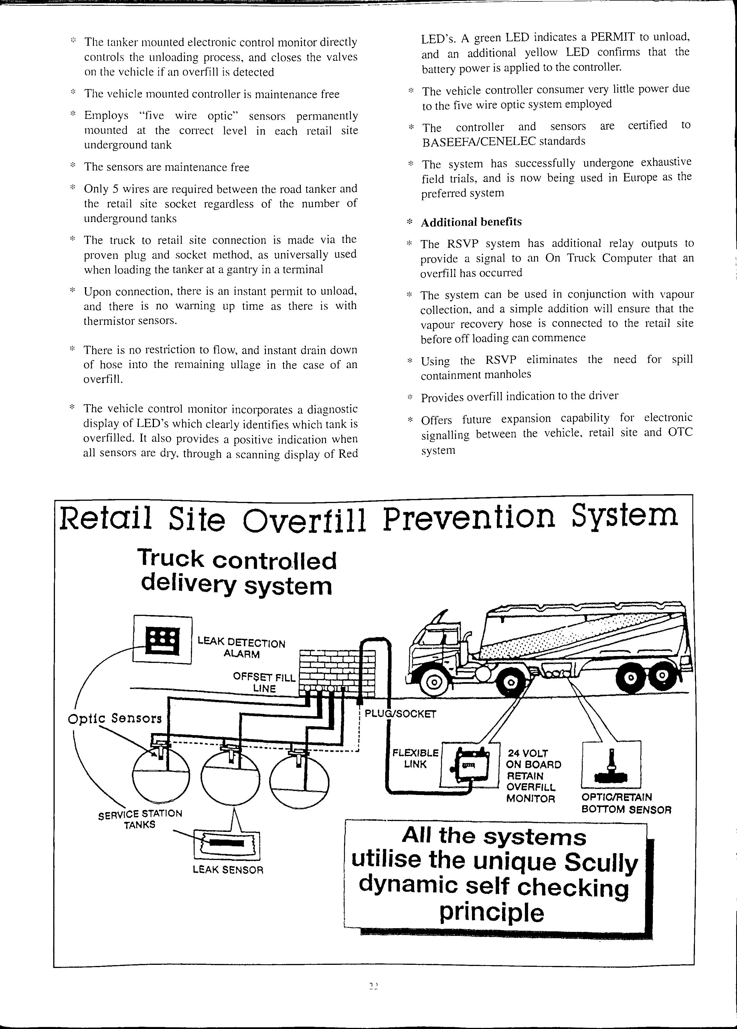
It con sists of a slim line case housing a keyboard , display and microproces sor control. A compact 40 column printer is attached to WETSTOCK MANAGER so that reports can be printed.
Each day WETSTOCK MANAGER will prompt the operator to enter the following data I. Opening stock for each tank
Closing sto ck for each tank
Deliveries into each tank 4. Sales through eac h of the pump s co nne cted to each tank
Temperature and water data can be entered into the system if required.
This set of data must be entered for each tank and is the minimum required for proper wet stock reconciliation and conformance to HS(G)41 legislation.
Once all the daily data has been entered, WETSTOCK MANAGER carried out the calculations and records all the data necessary so that the site can conform to the HS(G)41 legislation.
It may be argued that a system based upon a single daily reading using dipsticks cannot identify leaks.
Let's take a simple case.
A tank is mnning at an average reconciliation of 0.25% loss
The average sales are 1OOO litres per day.
The average losses are therefore 2.5 litres per day.
If a leak of a few drops per second or 0.05 gallons per hour (0.22 litres) now occurs then the daily losses become (0.22 x 24) + 2.5 = 7 .8 litres
As a percentage of sales this is 0.78% compared to the 0.25% before the leak.
This is quite a dramatic change in the reconciliation for quite a small leak rate and would be easily spotted on a cusum or moving average graph.
Each day WETSTOCK MANAGER will automatically generate a daily report that is acceptable by the LFCDA as a device producing reconciliation records of tank to pump throughput in order to comply with the licence conditions requiring such records to be kept.
This can be printed out at any time as can any of the previous 140 daily reports (see figure I).
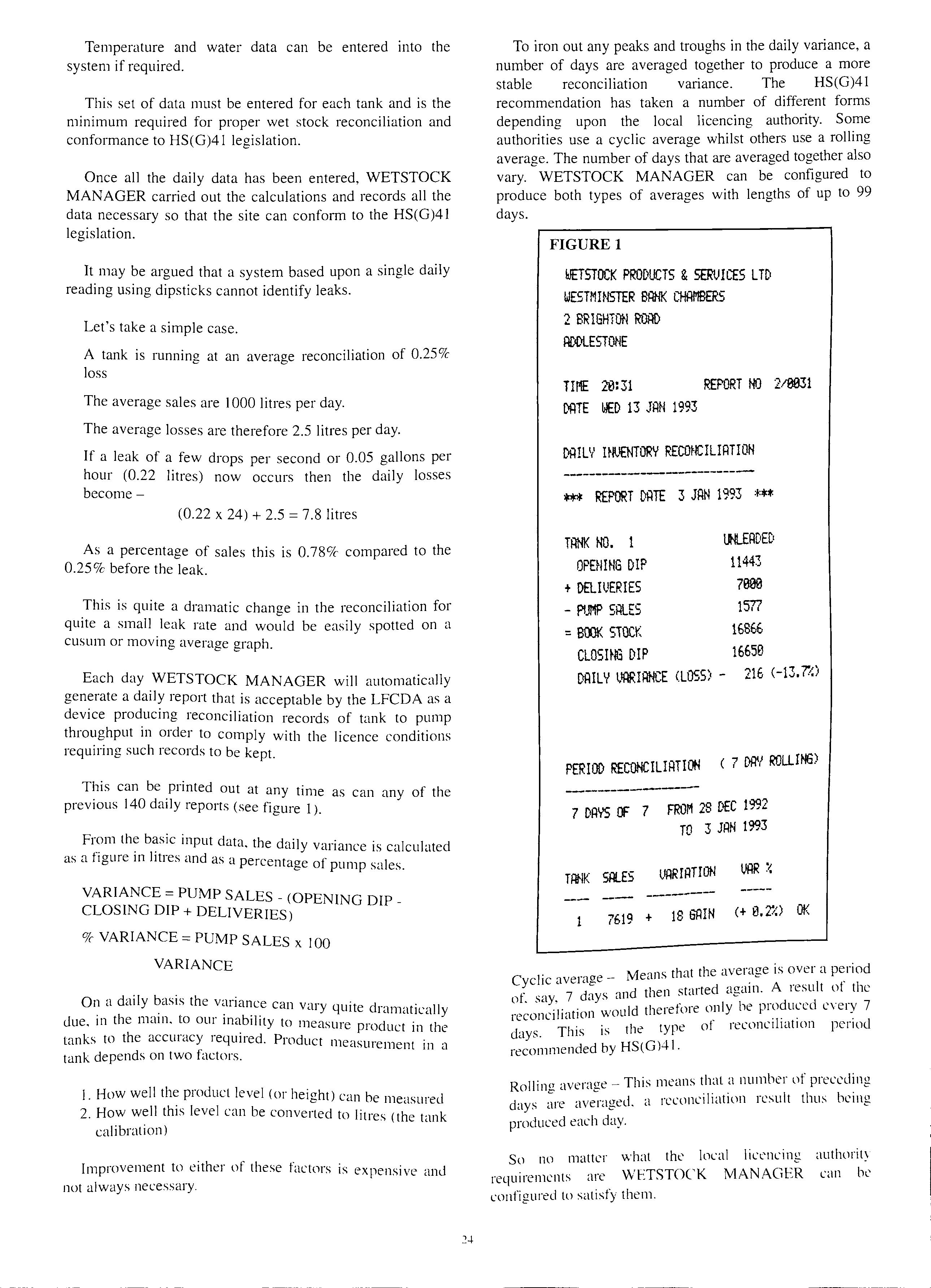
Fr?m input data. the daily variance is calculated as a figure 111 litres and as a percentage of pump sales.
VARIANCE= PUMP SALES_ (OPENING DIPCLOSING DIP + DELIVERIES)
% VARIANCE= PUMP SALES x IOO
VARIANCE
On a daily basis the variance can v·u·y qtii"te d. · II . . . . . ' iamat1ca y due. m the mam, to our 111ab1hty to measure product in the tanks to the accuracy required. Product measurement in a tank depends on two factors.
I. How well the product level (or height) can be measured
2. How well this level can be converted to litres (the tank calibration)
Improvement to either of these factors is expensive and not always necessary.
To iron out any peaks and troughs in the daily variance, a number of days are averaged together to produce a more stable reconciliation variance. The HS(G)41 recommendation has taken a number of different forms depending upon the local licencing authority. Some authorities use a cyclic average whilst others use a rolling average. The number of days that are averaged together also vary. WETSTOCK MANAGER can be configured to produce both types of averages with lengths of up to 99 days.
FIGURE 1
ESTOCK PRODUCTS &SERVICES LTD WESTMINSTER Bi:iNK CHAl'IBER5 2 BRISHTOt-1 RO® ROOLESTONE
Til'IE 20:31 REPORT 210031 OOTE WED 13 JAN 1993
Dli!LV UlllENTORY RECONCILIATION ---------------------
*** REPORT OOTE 3 JAN 1993 ***
TANK NO. 1 OPENING DIP + DELILl£RIES PUMP SALES = BOOK SiOCK CLOSHIG DIP
lH..EADECi 11443 7000 1577 16SE6 16650 DAILV LIJ'.IRIAN!.,"'E <LOSS) 216 (-13.(/,) PERIOD ( 7 M-I ROLLiti.3)
7 DAYS Cf 7 FROM 28 DEC 1992 TO 3 JAN 1993 HIHK Sil..ES ----7619 + 18 GAIN (+ 0.7':) OK
Means that the average is over a period Cyclic average ' · ' , 7 d nd then stmted agam. A 1esult ot the of, say, ays a . , , ·1· · iotild therefore only be p10du1.:ed c\e1y 7 reconc1 iation \.\ d TI ·. is the type of reconc1hat1on penod ays. 11s • recommended by HS(G)41.
Rollin<> average This means that a number of preceding days averaged. a reconciliation result thus being produced each day.
So no matter what the local licencing authority requirements are WETSTOCK MANAGER can be configured to satisfy them.
The best way to view data or trends in data is to present it graphically. WETSTOCK MANAGER is able to generate and print four types of graph.
Each of these graphs can be printed from any day in the 140 day data base and for a length of 30, 60 or 90 days.
Figure 2 shows a typical 30 day average plot for a tank that has a calibration problem. Note how the average reconciliation changes each time a delivery is made to the tank and then recovers as the tank is depleted over the next few days.
If at any point the reconciliation threshold is violated then a warning is printed indicating this event. This is shown in figure 3. (Note the warning is normally printed in red).
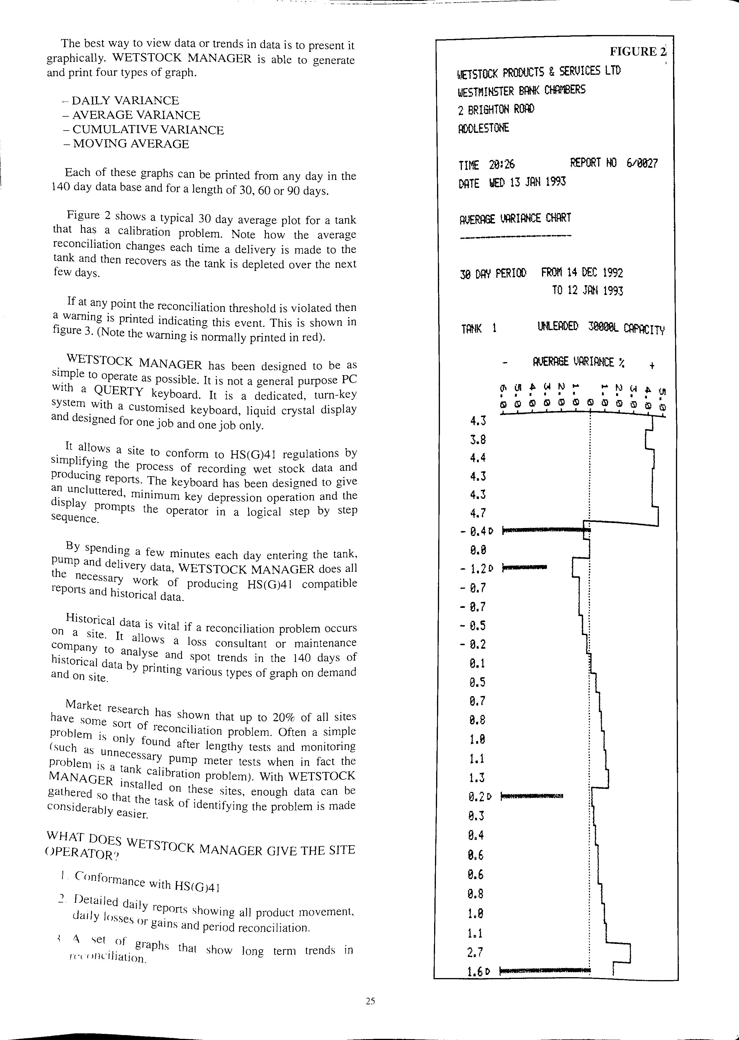
WETSTOCK MANAGER has been designed to be as simple to operate as possible. It is not a general purpose PC with a QUERTY keyboard. It is a dedicated, tum-key system with a customised keyboard, liquid crystal display and designed for one job and one job only.
It allows a site to conform to HS(G)41 regulations by the process of recording wet stock data producing reports. The keyboard has been designed to give uncluttered, minimum key depression operation and the display Prompts the operator in a logical step by step sequence.
By spending a few minutes each day entering the tank, pump and delivery data, WETSTOCK MANAGER does all the necessary work of producing HS(G)41 compatible reports and historical data.
Historical data is vital if a reconciliation problem occurs on a site. It allows a loss consultant or maintenance to analyse and spot trends in the 140 days of h1stoncal dat b · · . d d . a Y pnntmg vanous types of graph on eman and on site.
h Market research has shown that up to 20% of all sites ave sort of reconciliation problem. Often a simple problem 1s onl ,_. ( h · Y iounct after lengthy tests and momtonng sue as unn h ecessary pump meter tests when in fact t e p1oblem 1s t k . . K MAN · a an calibration problem) With WETSTOC AGER· ii b . msta ed on these sites enough data can e gathered so th h ' , . · at t e task of identifying the problem 1s made considerably easier.
Conformance with HS<G)41
..., Detailed ct ·1
ai Y reports showing all product movement, dady losses or ga· d . .1 · · · ms an penod reconc1 iat1on.
·'\ <>et of graphs that show long term trends in rt'1 r 111ciliation.
IETSTOCK PRODUCTS &SERIJICES LTD
WESTl'IIHSTER CHAMBERS
2 BRIGHTON R000
OODLESTONE
TIME 2e:26 REPORT 00 610027
DATE WED 13 JAN 1993
30 DAV PERIOO FROl1 14 DEC 1992 TO 12 JAN 1993
TANK 1 4.3 3.8 4.4 4.3 4.3 4.7 0.41> 0.0 1.21> t--····0.7 0.7 0.S 0.2 0.1 0.5 0.7 0.8 1.8 1.1 1.3 0.21> 0.3 0.4 0.6 0.6 0.8 1.0 1.1 2.7 1.61>
4. Over 4 months of historical data that can be accessed and printed as required.
5. An independent audit of the site ' s wet stock reconciliation.
6. Saves time in making lengthy moving average calculations and period reconciliation percentages.
7. Financial benefit if a loss of product can be diagnosed and put right quickly.
1. Common HS(G)4 l reporting and formatting.
2. The ability of a system to be configured to the interpretation of the local licencing authority whilst retaining the commonality of reporting.
3. Allows easier consultancy if a problem occurs.
WETSTOCK MANAGER is a complete system, including printer, and is on sale for around £1000. It is available housed in an attache case for neatness , portability and a small footprint.
If you would like to see how Wetstock Manager can revolutionise your HS(G)41 reporting then please ask for an on-site demonstration
WETSTOCK MANAGER is distributed through leading agents in both the retail and commercial sectors
Further information can be obtained from Malcolm Dodd at Wetstock Products and Services Ltd 0932 843506 or Geoffrey Wheeler on 0703 446044.
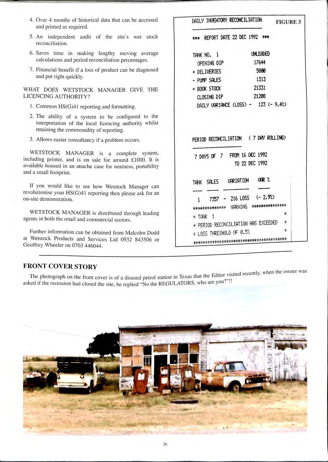
T 1e p otograph on the front cover is of a disused petrol stat10n 111 1exas t
asked if the recession had closed the site , he replied "No the REGULATORS, who are you·

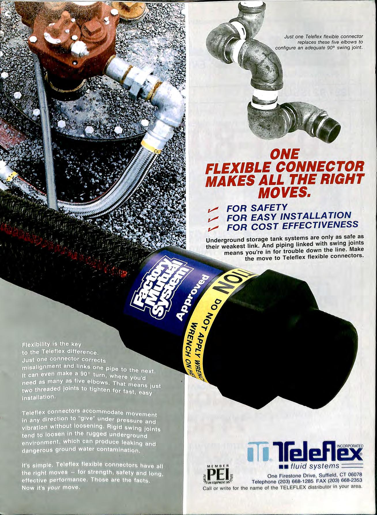
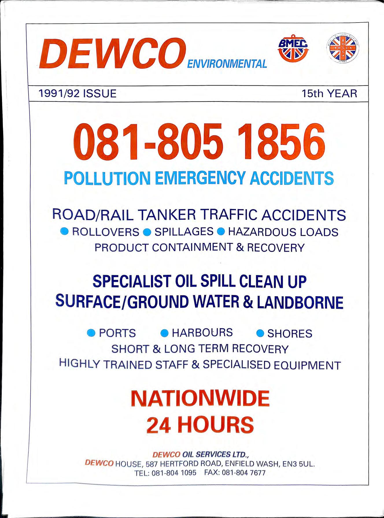


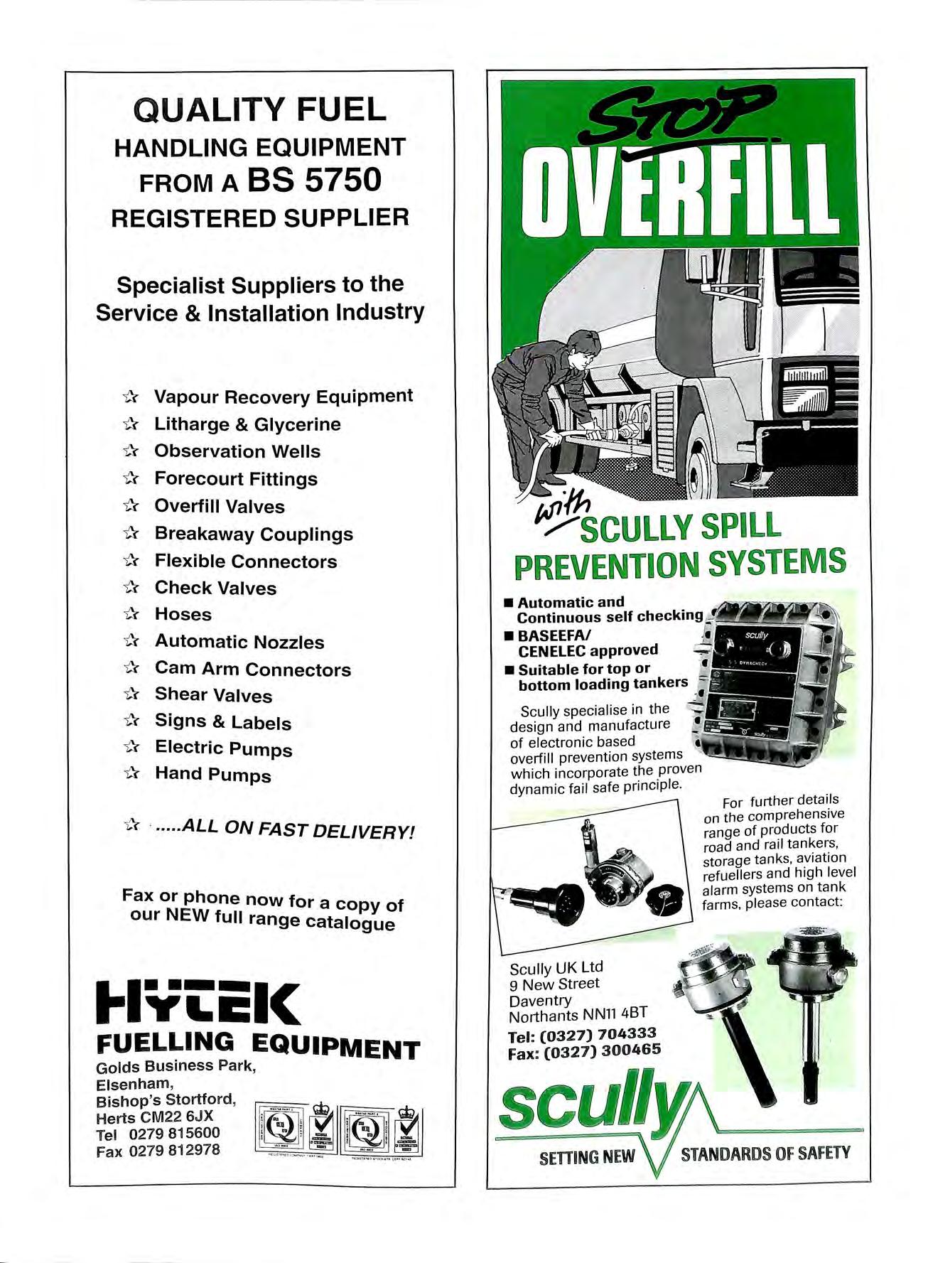


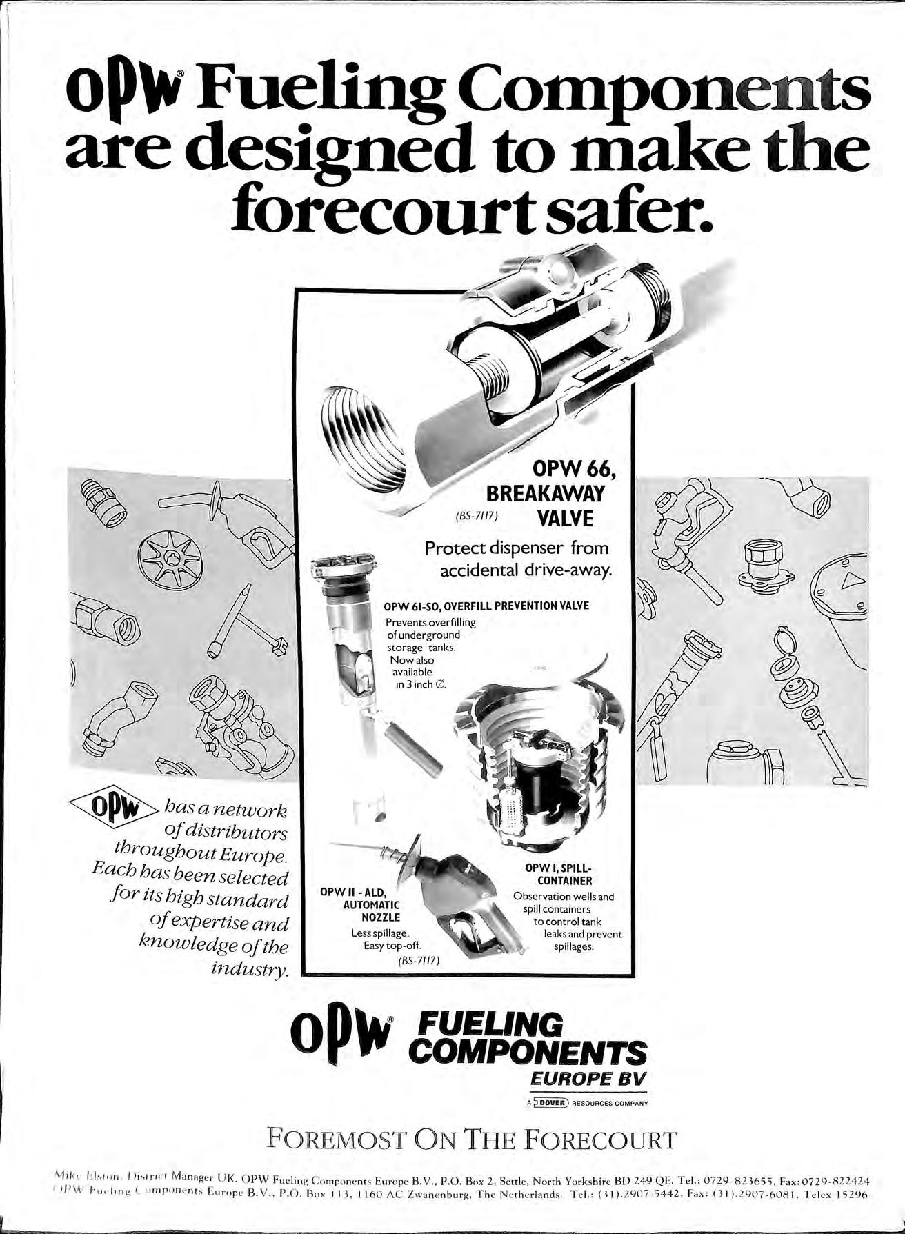
A WEFCO underground storage tank delivers petrol to the nozzle, where it's needed, not into the ground
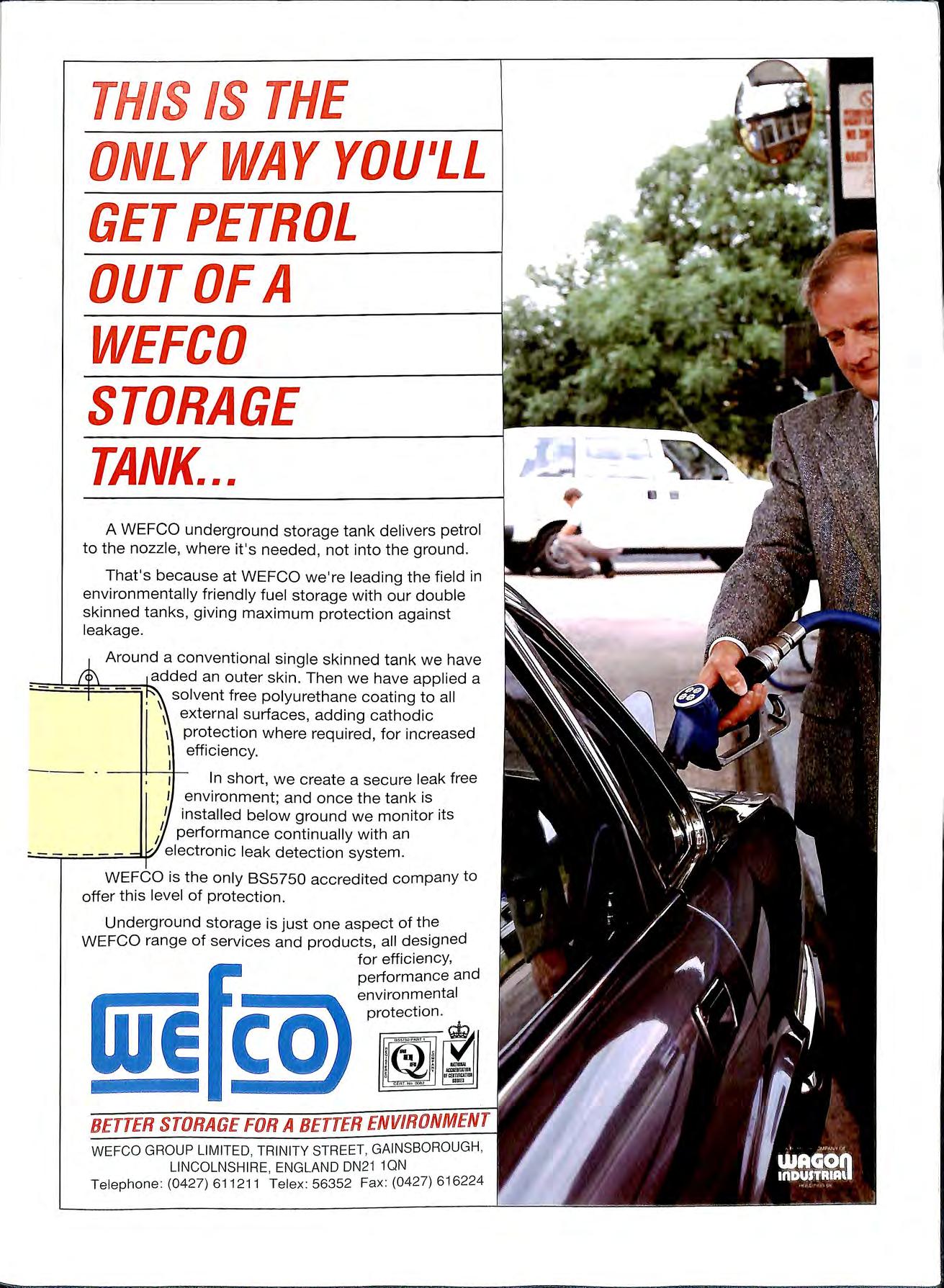
That's because at WEFCO we're leading the field in environmentally friendly fuel storage with our double skinned tanks, giving maximum protection against leakage.
Around a conventional single skinned tank we have an outer skin. Then we have applied a solvent free polyurethane coating to all \ external surfaces, adding cathodic 1 protection where required, for increased I efficiency. I
In short, we create a secure leak free environment; and once the tank is I installed below ground we monitor its / performance continually with an ___ electronic leak detection system.
WEFCO is the only BS5750 accredited company to offer this level of protection.
Underground storage is just one aspect of the WEFCO range of services and products, all designed
for efficiency, performance and environmental protection