
" ". , I•( .... The • ,,.
Intern a tion a l Confr:;: r e nce a nd E x hibitio(l [997 CONFERENCE EDITION VOLUME 36
Jeur nal of the Association for Petroleum and Explosives Administration
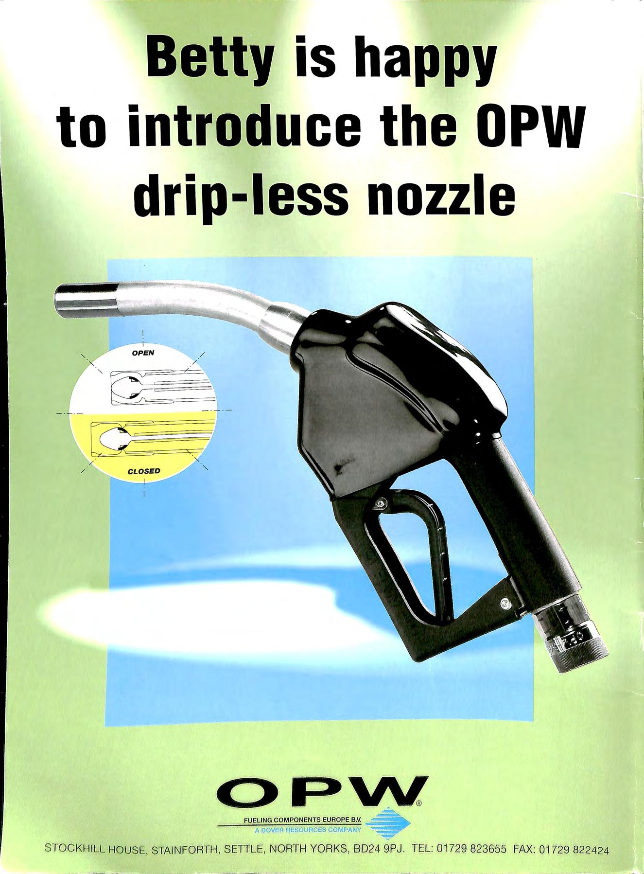
to introduce the OPW drip-less nozzle I I '- O PEN / /. F!JELING COMPONENTS EUROPE B V =---ii ADOVER RESOURCES COMPANY _.STOCK HI LL HOUSE , STAIN FORTH , SETILE, NORTH YORKS , 802 4 9PJ TEL : 01 72!9 823655 FAX: 822 424
Betty is happy
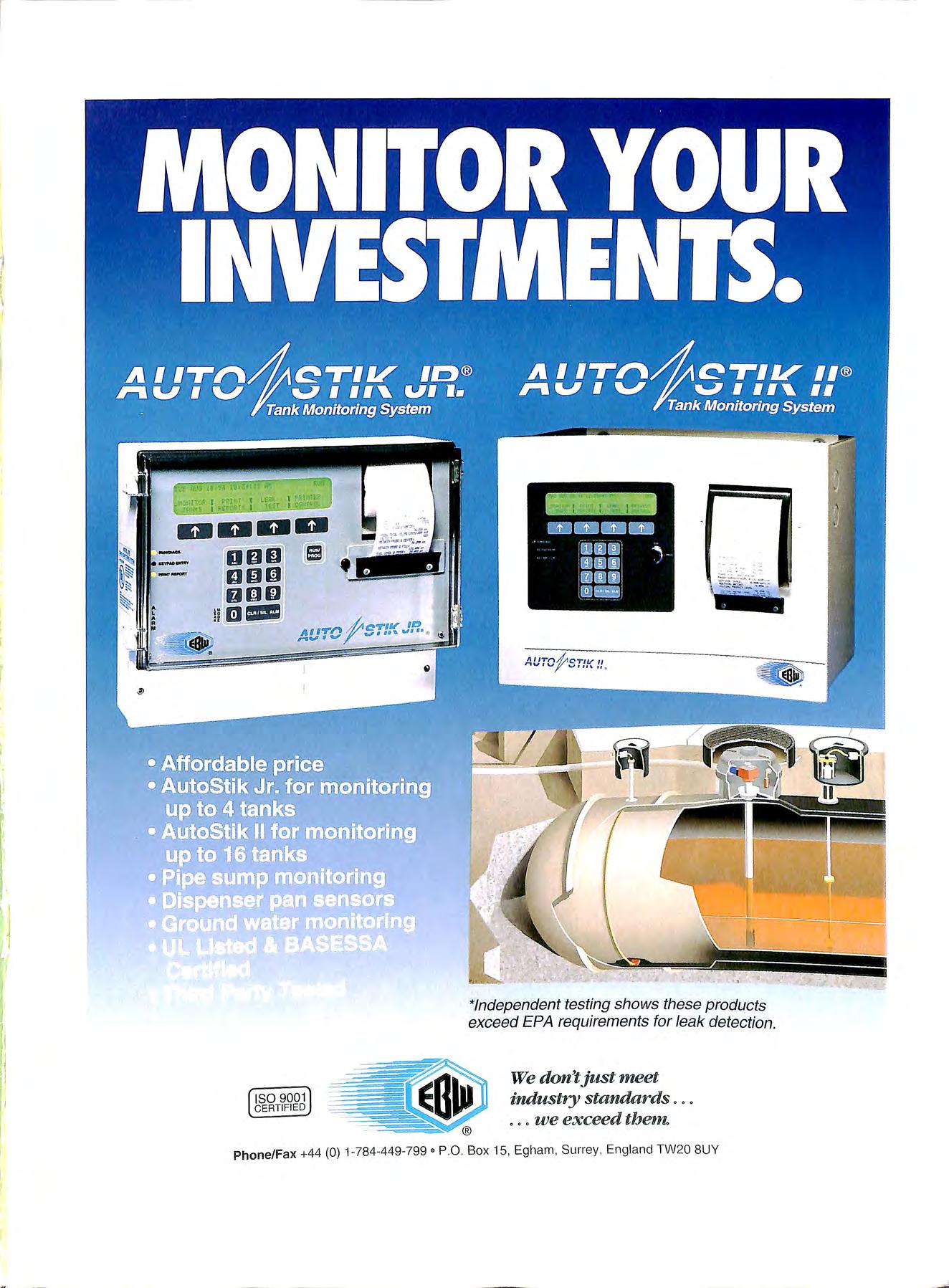
1 I I l. I, f CTIV ID Al ,.,.,,. ..,, I ••• • ,....,.,. • '11:1' ISO 9001 CERTIFIED *Independent testing shows these products exceed EPA requirements for leak detection. We don't just meet industry standards . we exceed them. Ph o ne/Fax +44 (0) 1 784-449 799 ° P 0 Box 15, Egh am, Surrey , Engl and TW20 8UY b5 ·· !l
 Scully On·Truck Computer
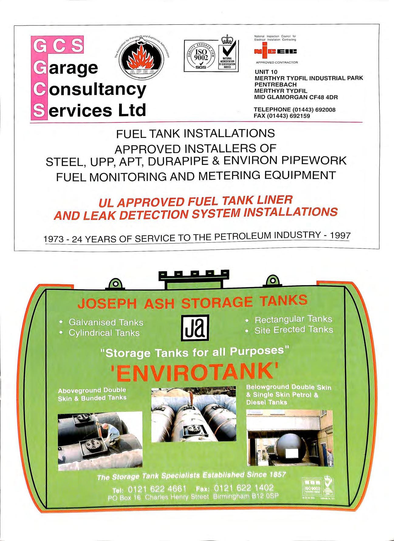
a rage onsultancy ervices Ltd National Inspection Council or Electnca lns atlat1on Contracting • •le EiC APPROVED CONTRACTOR UNIT 10 MERTHYR TYDFIL INDUSTRIAL PARK PENTREBACH MERTHYR TYDFIL MID GLAMORGAN CF48 4DR TELEPHONE (01443) 692008 FAX (01443) 692159 FUEL TANK INSTALLATIONS APPROVED INSTALLERS OF STEEL, UPP, APT, DURAPIPE & ENVIRON PIPEWORK FUEL MONITORING AND METERING EQUIPMENT UL APPROVED FUEL TANK LINER AND LEAK DETECTION SYSTEM INSTALLATIONS 1973 24 YEARS OF SERVICE TO THE PETROLEUM INDUSTRY 1997 0 0 J OSEPH ASH STORAGE TANKS @ID -NVIROTANK'
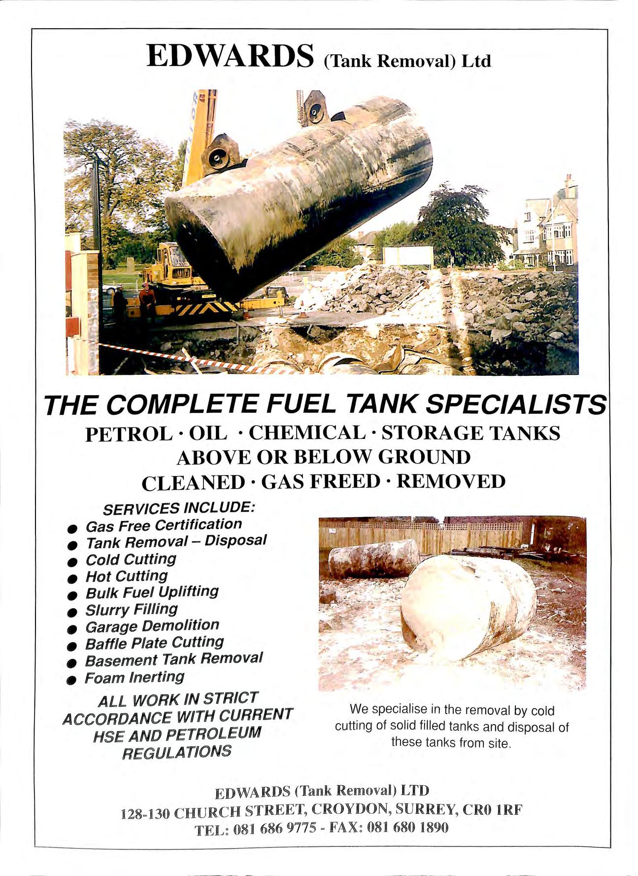
ED WARDS (Tank Removal) Ltd THE COMPLETE FUEL TANK SPECIALISTS PETROL · OIL · CHEMICAL · STORAGE TANKS ABOVE OR BELOW GROUND CLEANED·GASFREED·REMOVED SERVICES INCLUDE: • Gas Free Certifi cation • Tank Removal - Disposal • Cold Cutting • Ho t Cutting • B ulk Fuel Uplifting • Slurry Fi lling • Garage Demolition • Baffle Plate Cutting • Basement Tan k Remo val • Foam lnerting ALL WORK IN STRICT ACCORDANCE WITH CURREN T HSE AND PETROLEUM REGULATIONS We specialise in the removal by cold cutting of solid filled tanks and disposal of these tan ks from site . EDWARD§ (Tank Removal) LTD 128-130 CHURCH CRO lRF 08] 686 9775 081 680 1890

High integrity pipework systems for forecourt installations Distri b uted by PURFLEET FORECOURT SERVICES Tel: 017 08 86393 1 Ext. 219 fa x: 0 1708 864140 P-etrol·line -,,Jus Durapipe S&LP • No 1 UK manufacturer of polyethylen e p ipes • Superior electrofusion jointing system • High flow rates • Available in four sizes for suction and pressu re systems • Competitive prices • Nationwid e delivery PURFLEET FORECOURT SERVICES LTD s20 London Road, West Thurrock, e-mai l: purfleet forecourt services@ha rris-g ro up.co u k Grays, Essex RM 20 3BE LEDBURY WELDING & ENGINEERING LTD . NETHERWOOD ROAD, ROTHERWAS INDUSTRIAL ESTATE, (TEL: 01432 275566) HEREFORD HR2 6JU (FAX: 01432-358493) A COMPLETE RANGE OF ABOVE & BELOW GROUND STORAGE VESSELS QUALITY UNDERGROUND TANKS / QUALITY UNDERGROUND TA N KS DOUBLE A ND SINGLE SKIN LEA K DETECTION OVERFILL PREVENTION DEVICES MANWAY ACCESS FRAMES MULTIPLE COMPARTMENTS SPEC IALIST COATING ABOVE GROUND 9 FUll'V BLIND ED fOTAl Y EN l SE 600 GAllOIN TO 2 0 9000 GA ON .

CAMERON TEC HNICA L S ER VIC ES Specialist Forecourt Contractors C ont tzact o Up to 7 days I week 'We offer peace ofmind around the _clock to keep you/'. equipment safe and operational, with a dedicated out fJf hours phone line with engineers on standby o For all your forecourt and point of sale requirement O Environmental, emergency and accident expertise ?::'t£•,ts,,_· c.::,llttttct off'l M 6tt x f!x11("[i01CC (' {(°{ l_'.OH1Hut f1tl tC' i''(tll.Jidi.,t'j l(t1 f< Jt!itl1 tlJt 1Ptd !'-'O\li1.. t• CAMERON tel 01226 742 44 1 fax 01226 747441 CAMERON TECHNICAL SERVICES LIMITED Industrial Estate Platts Common Barnsley South Yorkshire S74 9SE
LONDON SE9 3TZ TEL: 0181-850 2211 FAX : 0181-850 5599

C.W.P. PIPEWORK CONTRACTORS SPECIALISTS IN PETROLEUM PIPEWORK Approved for UPP Pipework Installations & Dura pipe All Steel pipework Decommissioning of sites Vapour recovery Installation Alterations to existing sites 31 CLAREMONT ROAD MOU NT PLEASANT NEWHAVEN 'EAST SUSSEX BN9 ONG TEL/FAX: 01273 517702 WASTE MANAGEMENT NATIONWIDE FORECOURT DRAINAGE & INTERCEPTOR SERVICE Cleaning & emptying of interceptors and associated drainage systems found on garage forecourts • Interceptors • Catch Pits • Tank Tops • Gullies • Car/Jet Wash Pits • BucketTraps 111 Surface Drainage • Below Surface Channels Drainlines Water transported for tank testing plus treatment & disposal of the contaminated water. EVESHAM (01386) 4719HOl Petrol , oil & solvent tanks cleaned to OCTEL and Petroleum In dustry spec1f1cat1ons GlOUCESlfEIRl 507432 Head Office Grange Road , Botley, Southampton. S030 2GD Tel (01489) 782232/6 Fa)< (01489) 78 9821 GROU!P llrD SPECIALISTS IN PETROL PUMP AND PIPEWORK INSTALLATIONS.
INSTALLERS
AMERON AND SMITHS GRP. DURAPIPE AND UPP ENVIROFLEX AND ENVIRON. PRECISION TANK AND LINE TESTING EMERGENCY REPAIR SERVICE.
ROAD, NEW ELTHAM
D DC BUILDERS LTD FOR SERVICE QUALITY & RELIABILITY WE OFFER A COMPLETE SERVICE ON AND WORKS TO THE PETROLEUM MARKET D D C BUlilLDlER§ lL1'JD I ST CJLAJIR CCILO§lE CCJLA\'HAJLJL lilLFOIIml lE§§lE liG§ (())JP'A 52 Il6 Fax : 0Il8Il -55 ij 6095
APPROVED
OF:
2 BERCTA

BUILDING AND CIVIL ENGINEERING CONTRACTORS TO THE OIL COMPANIES FOR 24 YEARS C.R. RICHARDSON (CONTRACTORS) LTD DESIGN & BUILD •DI ;l:tDr!!I1J ;1!1 § i ;t:l i MAINTENANCE & REPAIRS An erl ey Court , Half Mo on Lane, Tel: 01732 838608 Hild enborough , Ke nt TN11 9HU Fax: 017 32 83806 4------------- - - --- --- ----.__ -.._..._ ----_.---== =··. ' == -==...)i::= FOAM SPECIALISTS RESIN GENERA TED FOAM FREEPHONE : 0800 592573 LICENCED AND APPROVED APPLICATORS OF BACEL HARDFOAM .. .... ...... . THE PROVEN, SAFE AND ENVIRONMENTALLY SOUND SYSTEM FOR THE HYDROPHOBIC NEUTRALISATION OF ALL UNDERGROUND FUEL STORAGE 1'ANKS R.G8 FO R THE TEMPORARY NEUTRAU SATIO N OF TANKS PRJOR TO EXCAVA TI ON , REMOVAL AND DEMOLITION. RG15 FOR THE SHORT TERM "MOTH B ALLING " OF TANKS WH ICH MAY REQU IRE TO BE RE-INST A TED FOR FUTURE RE-USE RG22 FOR THE SAFE NEUTRALISAT ION OF REDUNDANT TANKS FOR PERMANENT ABANDONMENT R.G30 FOR S URR O UNDING NEW TANK S AS AN AL TERNATf VE TO PEA-SHINGLE OR SUL PHATE RE.Sf.ST ANT CONC RETE We have over 25 years experience in the Petroleum Indu stry. Call us on Freephone 080() 592573 or Mobile: 0836 740500 Professional development TRAINING IN-COMPANY SHORT COURSES • Electrical Requirements for Petrol Filling Stations • Management overview of HSW Statutory Regulations includ in g: ' -Ma na gem e nt of Health & Safety at Wor k Re g s (MHSWR) Heal t h, Safety a nd We lfar e Re g s (WHSWR) Prov1s1o n & Use of Wo rk Eq uipm e nt Regs (PUWER) Perso nal Prot e cti ve Equipme nt at Wo rk Regs (PPER) • Essentials of Health & Safety at Work Sites • Introduction to Hea lt h & Saf et y Risk Assessment • ELECTRICITY AT WORK REGULATIONS (EWR) • Construction (Design & Management) Regs (CDM) • BS7 67 1 Requi rements fo r El ectr ical Inst a ll atio ns (16th Edition Wiring Regulations) • and Testing of In-Service Electrical lnsatallat1ons • EARTHING AND BONDING _ Reviews a w·d · 1 e range of nati o na l Codes of Practice a nd Statuto ry R . eq u1r eme nts Presenter: TERRY HEDGELAND BA. FI EIE. MIQA. Member of APEA ond IOP Phone: 01737 553328 SPECIALIST BUILDERS TO THE PETROLEUM INDUSTRY • FORECOURT INSTALLATIONS INCLUDING STEEL & PLASTIC PIPEWORK • SHO P REFURBI SHM ENTS • ELECTRICAL INSTALLATIONS • MAI NTE NANCEAN D REPAIR 01269 831038 FAX (01 2 69) 8 3 1 2 0 1 Acer Court ' Cross Hands Business Park . Cross Hands , Ca rmarth enshire 0 SA14 6RE "'" The Assoc iation for Petroleum and Explosives Adm inistration ' "" TEG , Wes! Wal es TEC
A. J. Bayliss (Stourport) Ltd Petroleum Engineers Petrol, Fuel Oil and Electrical Installations 11/12 HODFAR ROAD, SANDY LANE INDUSTRIAL ESTATE STOURPORT-ON-SEVERN DY13 908 TELEPHONE: 01299 824541-2-3 FAX: 01299 827638 ' SPECIALISING IN ALL ASPECTS OF FORECOURT PETROLEUM INSTALLATIONS, SERVICING AND PRECISION TANK TESTING FULLY ACCREDITED TO BS EN 150 9002: 1994 Care For The Environment Make Forecourts A Safer Place To Work And Visit.. . Provide Quality Solutions To Forecourt Engineering Problems rRI SBRllDGER VAPOUR RECOVERY PRESSURE VACUUM VAJLVES VAPOUR LOSS REDUCTION SYSTEMS UNDER PUMP/CHECK VALVES =. DESIGN & DEVELOPMENT INSITE - LINE TESTING RIS-Sl'O P OVERFILL PREVENTION DEVICE JIUSBRIDGER LTD o Stychens Lane, Bletrnin3ey, S1l.1lrrey RH 1 4LN Tel: ( +44 0188 3 743107 Fax: ( +44 0188 3 744342
1 I INSTALLING NEW TANKS? USEBACEL HARD FOAM RG30 for backfilling tanks • Absorbs hydrocarbons • High rigidity and cohesion • Insulates tanks on 't slurry in a hurry call now for a free estimate h Square· London· EC4A 3DE ·Tel 0171583 2007 ·Fax 0171583 2008 NASH Nas h & P a rtn e r s ha ve been wo rkin g in partners hip w ith the Re ta il Pet rol e um indu stry for a lm os t thirty yea rs, plannin g and d eve lop in g re tail in s ta ll ations from a s trai g htfor wa rd pump ch a nge to Europe' s larg es t fillin g s ta ti o n. Eve r y s tep of t he w a y , fr o m feasi bility s tudie s a nd s ur vey in g, pro ject m a n ag e ment a nd comm iss ioning, we tak e care o f eve ry d e ta il W h et he 1· a major o il co mpan y o r an indi v idu a l d e aJe r, ou r c li e n ts a re ass ur e d of th e Na s h co mmitm e nt to qu a lity and a dh e re n ce tn BSS750, ba c ke d by up-t o-the- minu te tec hno logy, inn ovat io n a nd ex p e rti se Fru m a g ree nfi e ld s ite to a full y ope ra tional in s ta ll at io n , Nas h & Pa r t ne rs d e li ve r uea ti ve ye t hi g hl y prac tica l s o luti o n s. + A IK HIT ECTS + SU l\VEYO RS • TOW N !'LANNERS -$ i>l\Cl j ECT MANAGERS l' ROl'ERTY i\ AS H & P A RTNE R S LTD+ S tat ion A pproa ch + S outhgate+ Chi che s te r +
' t ._,.\ \ e Zero Permeability •Lightweight •Robust • Smooth bore • Non-corrodible e Electrofusion jointed e Designed and manufactured under a BS EN ISO 9001 Quality management system 'Tel: • • -Fax: Fax export de11>t: Tele x.: • +44 (O) 1543 279909 +44 (O) 1543 279450 44 (O) 1543 278095 339145 D UPIPE G .... eetrol·line RIUS Suitable for vacuum and pressure applications in 50mm, 63mm, 90mmand _L 1_1omm I sizes f!.A Glyn w e d Int e rn at io n a l bu* ess
the complete forecourt advertising kit For further information on the full range of Elaflex products contact: F.liverside House, Plumpton Road, Hoddesdon, Herts EN11 OPA. Telephone 01992 451494. Fax 01992 451496

DAVID PLUMB & CO LTD 169 Frenches Road, Redhill RH1 2HZ Telephone: 01737 767524 Service to the Petroleum Industry Since 1966 Member A.P.E.A. The safe alternative to water-filling of petrol tanks for certain applications Using our oil/water separator, we can dispose of water from petrol tanks at a fraction of the cost of tanker hire Work undertaken by fully trained and medically ,. _ certificated personnel Hot and cold cutting, removal and documented disposal of redundant oil and petrol tanks. Product uplift and transfer • Converting double=compartment tanks to single Solid filling of redundant tanks • Cold cutting open and dispos i ng of solid- filled tanks Excavation • Tank removal • Contaminated soil disposal and reinstatement
• 0 0
DRIP STOP diesel nozzle
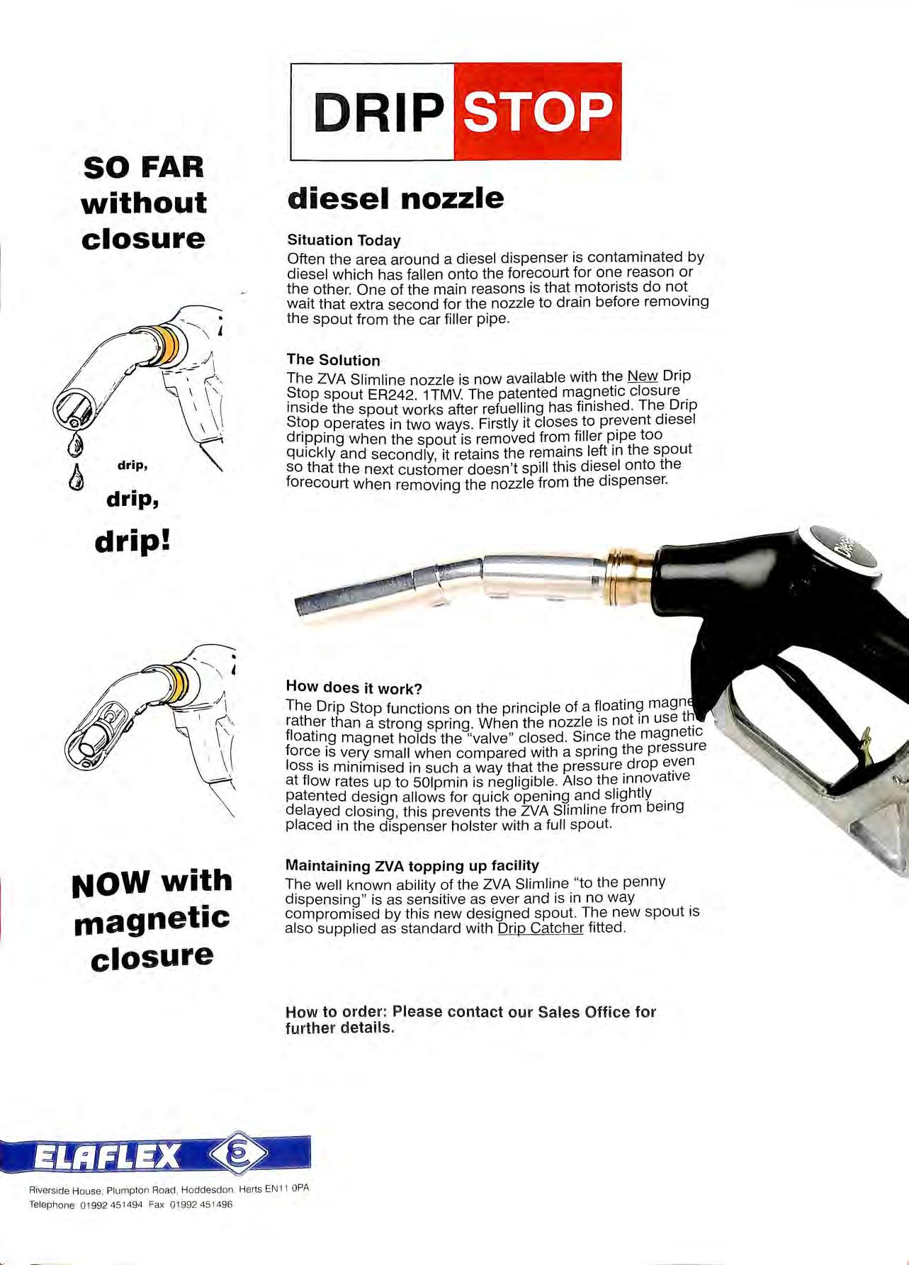
Situation Today
Often the area around a diesel dispenser is contaminated by diesel which has fallen onto the forecourt for one reason or the other. One of the main reasons is that motorists do not wait that extra second for the nozzle to drain before removing the spout from the car filler pipe
The Solution
The ZVA Slimline nozzle is now available with the New Drip ?tC?P spout ER242 1TMV. The patented magnetic closure 1ns1de the spout works after refuelling has finished The Drip St?P in two ways. Firstly it closes to diesel dripping when the spout is removed from filler pipe too quickly and secondly, it retains the remains left 1n the spout so that the next customer doesn 't spill this diesel onto the forecourt when removing the nozzle from the dispenser.
How does it work?
The Drip Stop functions on the principle of a floating magn than a strong spring. When the nozzle is not in use floating magnet holds the "valve " closed Since the magnetic fore€'. is very small when compared with a spring the pressure loss is minimised in such a way that the pressure drop at flow rates up to 501pmin is negligible. Also the 1nnovat1ve patented design allows for quick opening and slightly delayed closing , this prevents the ZVA Slimline from being placed in the dispenser holster with a full spout.
Maintaining ZVA topping up facility
The well known ability of the ZVA Slimline "to the penny dispensing " is as sensitive as ever and is in no way compromised by this new designed spout. The new spout is also supplied as standard with Drip Catcher fitted .
Ho w t o or de r: Plea s e con ta ct our Sa les Office for f urther de t ails.
SO FAR without closure I ,-=----=\ f;: ---drip, drip, drip! NOW with magnetic closure
__, -
Riverside House Plumpton Road Hoddesdon Herts EN1 1 OPA Telephone: 01992 451 494 Fax 01992 45 1496
of the Association
Talking Point
The first meeting of the ACDS sub committee has been held to consider on the HSE consultative document regarding new legislation for petrol storage, and recommendations are to be made for the legislation to come into force on I April 1999. Guidance will eventually be given to the enforcing authorities to ensure petroleum licences run to this date.
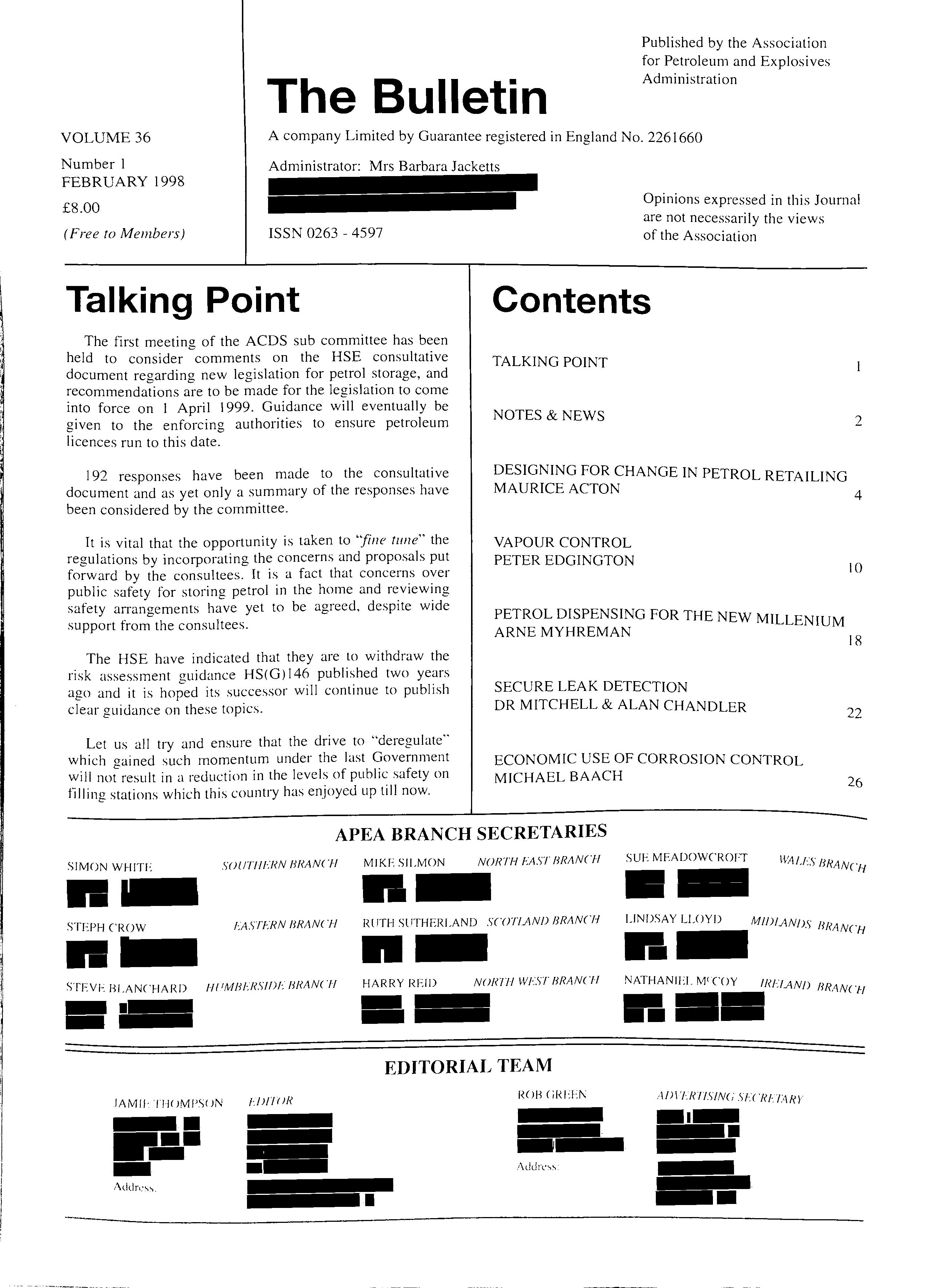
192 responses have been made to the consultative document and as yet only a summary of the responses have been considered by the committee.
It is vital that the opportunity is taken to "fine tune" the regulations by incorporating the concerns and proposals put forward by the consultees. It is a fact that concerns over public safety for storing petrol in the home and reviewing safety arrangements have yet to be agreed. despite wide support from the consultees.
The HSE have indicated that they are to withdraw the risk assessment guidance HS(G) 146 published two years ago and it is hoped its successor will continue to publish clear guidance on these topics.
Let us all try and ensure that the drive to "deregulate'" which gained such momentum under the last Government will not result in a reduction in the levels of public safety on filling stations which this country has enjoyed up till now.
Contents
TALKING POINT
NOTES &NEWS 2
DESIGNING FOR CHANGE IN PETROL RETAILING MAURICE ACTON
VAPOUR CONTROL PETER EDGINGTON
PETROL DISPENSING FOR THE NEW MILLENIUM ARNE MYHREMAN
SECURE LEAK DETECTION DR MITCHELL & ALAN CHANDLER
ECONOMIC USE OF CORROSION CONTROL MICHAEL BAACH
VOLUME 36 Number I FEBRUARY 1998
Bulletin Published by the Association for Petroleum and Explosives Administration
company
Guarantee registered in
2261660
(Free
ISSN 0263 4597
The
A
Limited by
England No.
Administrator: Mrs Barbara Jacketts £8.00
to Members)
Opinions expressed in this Journal are not necessarily the views
4 10 18 22 26 APEA BRANCH SECRETARIES SIMON Wl-llTlo SOl!Tll l:RN Hl<ANCH STEPH CROW EASTl:RN BRANCH STEVE BLANCHARD Hl'MHl:RS!f)f: 8RANCH f/\MIJ· TI ft JMl'SI JN UJ/1111< MIKE SILMON NOR"IH !:AST BRANCH Rl!TI-1 SllTI-IERLAND SCOTl.ANIJ BRANCH HARRY REID NOl<Tf-1 Wl:ST lll<ANCll EDITORIAL TEAM ROB 1 /\ddrc'" SUE MEADOWCROFT 11'4//·<· ' · :., Bl<AN('f{ LINDSAY LLOYD Mff)fANI>S /if<AN<H NATHANILL M'COY fRF!ANn RRA.N<H .\/)\I.Rf/SIN<; VC HF7M<l'
notes and news
AN EXCITING OPPORTUNITY
Way back in 1986 the APEA Council was sitting around a large table at the LFCDA headquaiters. The decision had been taken for the Association to become a Limited Company and Rod Jones had made known his decision to retire from being Treasurer to be effective from the ending of the old Association. The question was raised as to who would take ·aver from Rod. I looked at those sitting around the table and asked myself who amongst those pr;sent has had any experience of operating the accounts of a small business. That is how I came to stick my head above the parapet and offer myself for the post.
Since I started as Treasurer in mid 1987. the Association has grown and developed in many ways as have the demands of the post on my spare time. (Any of you who are involved in running your own small business will know just how precious spare time can be). As a result a few months ago I decided that I would not stand for re-election at the next A.G.M. and passed on my decision to the Management Committee. As a consequence, the role of Treasu;er has been re-examined in order to reduce the workload. It has been agreed that a firm of accountants will take over the book-keeping and many of the functions being can-ied out by the Treasurer and by the Administrator. Since the APEA financi_al coincides with the calendar year. it would be better 1f tins change was introduced to be f" t. f J e 1ec 1ve rom t le I st January 1998, and this is now well under way.
The change is inevitably going to mean a chanoe in mtemal procedures. All expenditure 111 f't t .11 d"' 1 ure w1 nee to be authorised by the appropriate committ I · ee c la11 man and those subm1ttmg claims will need to b c more thorouoh in preparing them. As I write this I have d 1 d 1 "' · ra te t le first issue. New claims and expenditure proced h mes ave been aoreed which I am ce1tain will need to b . "' · · e <1111ended as tect11· problems arc ironed out. · · mg
Now the most important thiilo "'now is who w Id 1·k become our Treasurer ·it tl · ou 1 e to · ' le next A.G.M 7 TI be less onerous than of late and c· · ·. le should . . . -. · . . . an piove 111terest1110. As in any association, <1 post 1s wh·it Yll k "' ' u 111·1 ·e ol t SI I he at all interested and want to k ' 1 · lou d you · now more ·1b t tJ · exciting opportumty, please contact me. ' ou us
TOM WIGFULL
NEW PETROL LEGISLATION PROGRESS FOLLOWING CONSULTATION
Overall, most commentators welcomed the proposals, supporting the introduction of a consent scheme for petrol stations and the removal of licensing requirements from workplace storage sites. On the proposals for unloading, most people agreed with the move towards a more simplified Schedule (draft Schedule 3 ). but said that it did not distinguish sufficiently clearly the duties and responsibilities of the site operator and those of the driver, or set out what was required for different types of delivery e.g. assisted, driver-only or split deliveries. We will take these views on board and re-structure the Schedule.
When I wrote for the November edition of The Bulletin, I hoped we would be able to put final draft Regulations to HSC in February 1998. We have now finished a full analysis of the comments, and are working with one of the HSC's Advisory Sub-committees to amve at a final set of revised proposals. This is likely to take a couple of months or so. We will then be in a position to put final proposals to HSC. If they agree, we can submit the legislation to the Minister, hopefully during the early summer.
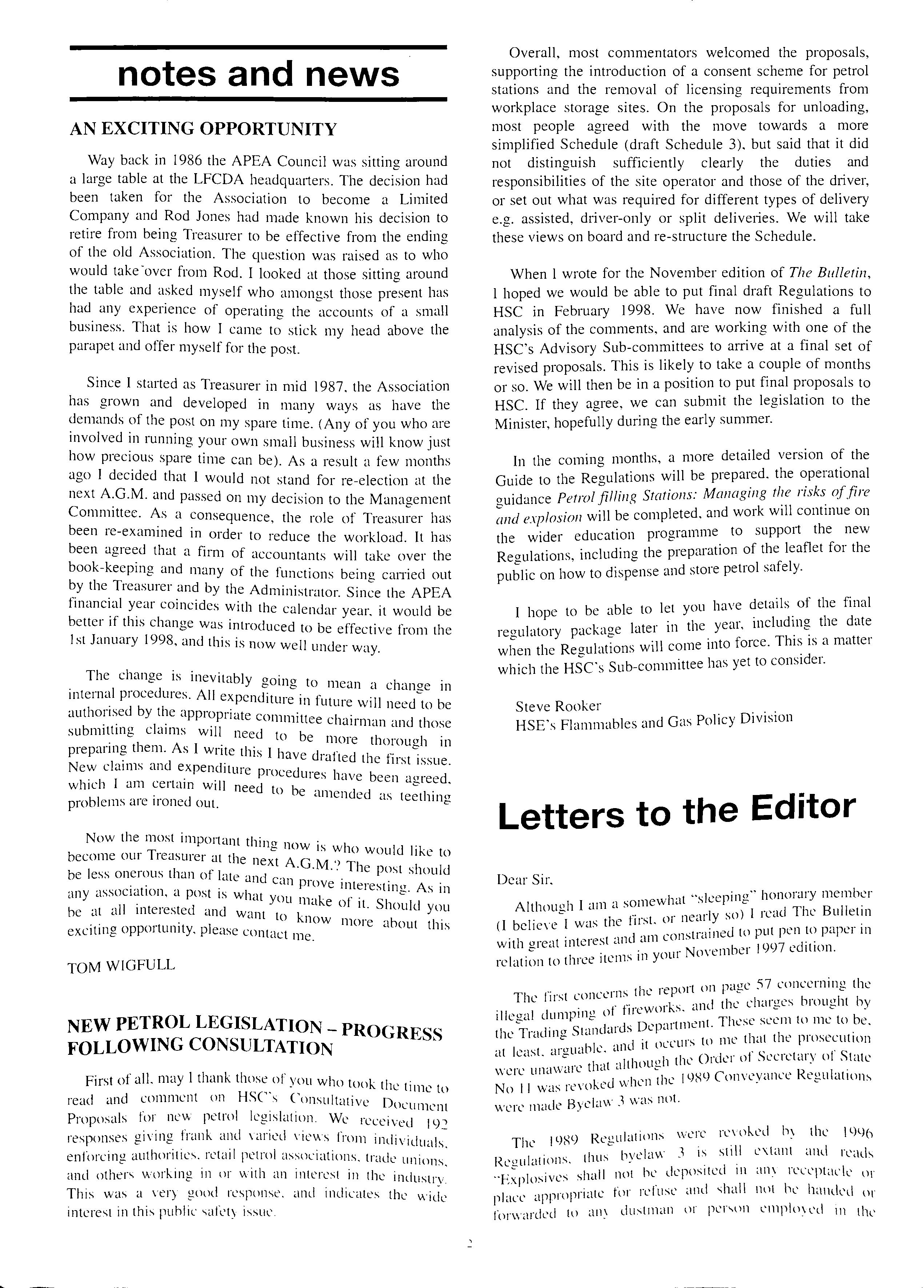
In the coming months, a more detailed version of the Guide to the Regulations will be prepared. the operational ouidance Petrol filling Stations: Managing the risks of.fire "' I I 011 w1·11 be completed and work will continue on mu exp os1 • the wider education programme to support the new Regulations, including the preparation of the leaflet for the public on how to dispense and store petrol safely.
I hope to be able to let you have of the final 1 k e late! 111 the year mcludmg the date regu atory pac ·ag • -: when the Regulations will come mto force. is a matte1 which the HSC's Sub-committee has yet to consider.
Steve Rooker HSE's Flammables and Gas Policy Division
Letters to the Editor
Dear Sir, I ·it "sleepina" honorary member Altl <>11 I am a somew 1< • "' 10u,,, _ 1 so) I read The Bulletm (l believe I was the hrst. o1 neai _Y , d ·onstruned to put pen to p<1pe1 111 with great interest an am c N. ' 1ber f 997 edition relation to three items in your oven
'"
First of all. may I thank those of you who tC)l)k tl · le t 1111c to read and comment on HSCs Consultative D · ocu mcn t Proposals for new petrol legislation. We received ILP responses giving frank and varied views from enforcing authorities. retail petrol associations. trade unions. and others working in m with an interest in the industrv. This was a very good response. and indicates the wilie interest in this public -;afrty issUL'.
. 1 , ·eport on paoe 57 concerning the TI , r . ·t concerns t le I "' le ll s ·k I the chaPTCS brou "ht hy . d . o ot tirewo1 s. ant "' "' illegal UI11P 111 -=- t Tlwse seem to me to be I T I St·rnd·1rds Depm tmen t le ntl mg ' ' · t me that the prosecution I ·a ·1bk and it ou.:u1s o at east. <llcll' · of Ill' Orckr of Secretary of State , , ·1w·1re that althou,,, 1 t w1.:1c un, ' , 1 , 1989 Conveyance Regulations No 11 was revoked wlll:n t 11: I By ,hw 1 was not. were mate t: ' ·
Il)XlJ R •ouhtinns \VL'l"C revoked the \ L)L)() The ' t,,, ' 11111 s b)'elaw 3 1s still extant and reads Reg1Ilations. · F 1 · sll·tll 110t he de11os1ted 111 an\ receptack \\r ,xp os1ves . ' place appropriate for rl'l use and ..;hall not he handed or forwarded to dustman or per-..on L'lll]lill\L'd 111 the
removal of refuse, or shall explosive be conveyed in any carriage or boat appropriated for the removal of refuse". Perhaps after more than 60 years in the business (and continuing) I am a little more "up to date" than some, but the way that the 1875 Act and its subordinate legislation is being updated means that odd things like this can easily be forgotten.
The second concerns the article on Electrostatic Hazards on pp 68-72, it is often said that unexplained accidents in the explosives industry are blamed on grit and those in the petroleum industry on static. In this content I was surprised not to find in the bibliography reference to the work of Klinkenberg who did some fundamental work for Royal Dutch Shell in 1958.
The third concerns your 40th Birthday in 1998, which means that the association was f01med in 1958. When I joined the Explosives Inspectorate I was given petroleum matters as my special interest and I soon met John Frid who was trying to get the fledgling association "off the ground".
I saw it as a convenient (and free) way of taking soundings from the enforcement side with myself acting as a bridge to the Institute of Petroleum (albeit unofficially) and I am pleased to see the Association now recognised in its own right long may it continue.
World of Tourers Ltd were aware of the disused tanks when they first occupied the former filling station and in effect accepted responsibility by carrying out the works to have them made temporarily safe. In accordance with Fire Authority policy, they applied for and were granted a Breathing Condition licence to maintain the tanks in a temporary safe condition. This licence, initially issued for one year was renewed at the request of World of Tourers Ltd for a further one year with the Fire Authority attaching a caveat that the tanks must be rendered permanently safe before the expiration of the renewed licence.
When World of Tourers Ltd failed to honour this caveat, an Improvement Notice was served requiring the company to carry out works to render the tanks permanently safe from the risk of fire or explosion.
Subsequent to the service of the Improvement Notice, a great deal of correspondence passed between the company and the Petroleum Officer (PO) issuing the Notice regarding who was responsible in law for the tanks, with the company. that it was the property owner and the PO explammg the occupiers legal responsibilities under Section 73( 1) of the Public Health Act 1961 and the common duty of care under Occupiers Liability Act 1957.
Yours
sincerely G. J. Jeacocke
COMPANY AND DIRECTOR FINED FOR FAILING TO COMPLY WITH AN IMPROVEMENT NOTICE
On 7 November 1997 the Dewsbury Magistrates imposed fines of£ I .OOO each on World of Tourers Ltd and their director. Mr C A Bradley. after they pleaded guilty to failing to comply with the requirements of an Improvement Notice contrary to Section 33( I )(g) of the Health and Safety at Work etc Act 1974 !HSWA). Costs of £1.055 shared equally between the two defendants were also awarded by the Magistrates in favour of the Fire Authority.
The Improvement Notice required World of Tourers Ltd. trading as Excel Caravans. to carry out the works to render safe from the risk of fire or explosion five disused petroleum spirit storage tanks at the premises they occupied at Leeds Road in Birstall. West Yorkshire.
The history hehind this prosecution is not unusual insofar as World of Tourers Ltd found themselves 111 a d d h h ·11esse's typically pre 1cament experience y many us1 · · · · second hand car dealers. who leave redundant petrol I ii I mg stations only to find that they have inherited a statutory ohligated for the safety of' the tanks.
Occasionally. al the intervention of the PLA. the tanb will he made safe by the owner who feels he has a moral ohligation to do so. or as is often the case eventually hy the unwilling occupier with or without any financial assistance frr 1111 thl' owner
When the time on the Notice had expired and after the company d1rector stated durino an interview under caution that he had no intention of undertaking th k. e wor s, the PO. had no. alternative other than to instigate legal proceedmgs agamst the company and its sole director.
World of Tourers Ltd were charoed w 1 "th "c t · o on ravemn£? the requirements of an bnproi•ement Notice dated 7 Fehruarv 1997; therebv committino an c· J t L L < 11 rarv to Section 33( I )(g) <?f th HSWA." ·
C A Bradle.y was charged "that with his consent or conm1•a11ce as a director of the co1111umv 1 World <Jf -r,, · · " urers Ltd contrm•ened the reqwrement.\' <?fan Improvement Notice dated 7 February 1997; thereby co111111ittinx an <JfTence cm1tra1:v to Section 33( I HR) <1f the HSWA."
For reasons best known to himself, the owner of th property unexpectedly paid for three of the five tanks to
made safe three months after the Improvement Notice had expired and then three k wee s before the case was heard by the Magistrates. paid for th remaining two tanks to be made permanently safe. e I Scl'lion 1-fS\VA. 10ffl'nn_·-.. hy
,I ,j I ;1
b:
Hodit'' Corporate I
"Designing for Change in Petroleum Retailing"
 by Maurice Acton, Chairman, MTA Design Limited, London & Singapore.
Introduction
MTA is a multi-discipline inte rn at io n a l design compa ny b ased in Lon don and Sin ga p o re. We s p ec ialise in desi g ning for the Oil Indu st ry. Within th e downstream sec tor we und e rta ke corporate/ retail identity des ign a nd brand development covering all a reas of C-s tore a nd forecourt , product a nd p ac k ag in g d esig n
Wh a t differentiates MTA from o ur competitors is not ju st o ur experience but our m e th o d o logy. We approach proj ects strategica lly and create inn ovative d es ig n solutions with the emphasis on practical, effec tiv e and commercially s uccessful implementation. Our multi-di sciplined expertise in a rc hitec ture , environment, produ c t de s ign , graphic communications, to ge th e r with o ur ex perience a nd expe r tise in tec hnical des ig n a nd impl e mentation , combine to c rea te customer rel eva nt , p rac tic a l, cost effective , so luti o n s with s tron g vi s ual impac t and m a rket differentiation.
Design for re-imaging
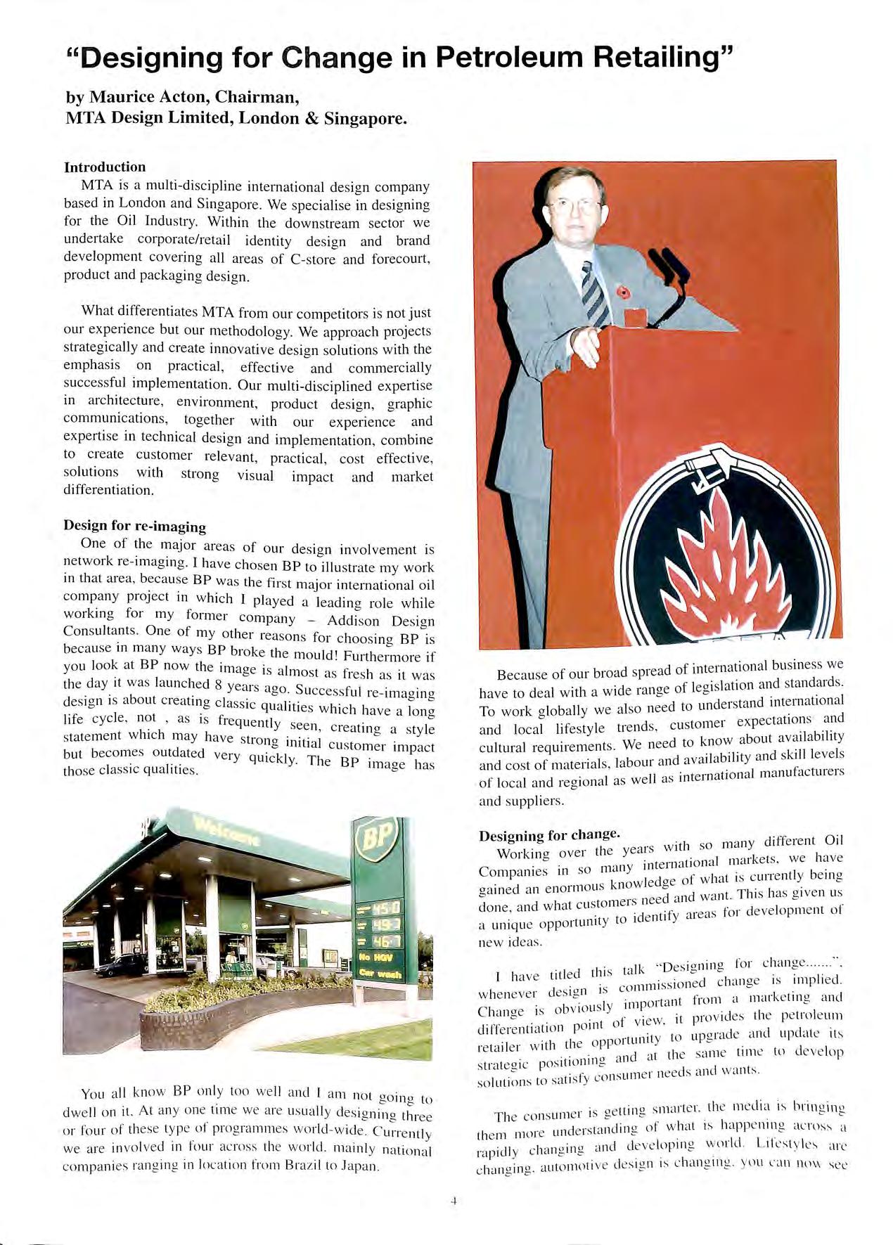
One of the major areas of o ur des ig n involvem e nt is network re- im ag ing. I h ave c h ose n BP to illu s trat e my work in th at area, beca use BP was th e fir s t major internation a l o il co mp a ny proj ec t in which I played a leadin g role w hil e wo rkin g for m y form e r com p a n y - Addi s on D es ig n Co n s ulta nt s. One of m y o th e r reaso ns for choosino BP is b becau se 111 m a ny ways BP broke t he m o uld' Furtherm ore if yo u look a t BP no w th e im age is a lm ost as fresh as it wa s the cl a y it was launched 8 years ago. Successful re-im ao in o b b b design is a out creatrng classic qu a liti es which h ave a lo ng life cycle , ' as is frequ e ntly see n, creatin g a styl e state m en t w hich may h ave s trong initial customer imp ac t but becomes o utd ate d very quickly. The BP im aoe h as th ose cla ss ic qualiti es ' 0 •
Yo u a ll know BP o nl y to o we ll a nd I a m n o t go in g to dw e ll on it. At a ny one tim e we a re us ua ll y des ig nin g three o r four of these ty pe of pro gramm es w o rl d w id e C urre ntl y we are in vo lved in fou r acro ss th e wo rl d mainl y nat io na l co mp a ni e s ranging in locat ion from Bra z il to J apa n
cl
Because o f our broad sp1 ea of 1 sla ti o n a nd sta nd ards 1 d e ra n oe o eg 1 h ave to deal wit 1 a w i 0 d d e i·sta nd inte rn at io nal II I 0 nee to un ' To work globa Y we a s expectation s a nd 1 t. d s c ustorne1 a nd lo cal hfes ty e i e n ' d k w about avai la bilit y . w ee to no ' c ultura l reqmre m e nt s. e n 1 bility a nd ski ll leve ls .· I I bour a nd avai a a nd cos t of rnate1 ia s, a . _ ti"o irn l m a nu fact ure rs 1 II as m te1n a of loca l a nd re g 1o na as we ' a nd s uppliers.
Designing for chan ge. . 1 so man y d ifferent Oil 1 yea rs w 1tl Workino ove r t 1e ' I nn rke ts we have "" an int e rn a ti o na ' , . Co mp a m es 111 so 111 < Y cl of w hat is c urre ntl y be 111 g knowl e ge · oa in ecl a n e no rm o us d cl wa nt. This has g ive n us o ers nee a n ' clone a nd w ha t c us tom t. eas fo r deve lop me nt ot· ' · to 1d e nt1 Y a i ' a uni q ue opportu nity new id eas
· ' D ·onin o fo r c ha ng e I ta lk es 1 _ c J have titl ed t 11 5 < . .. · c ha n cr e is impl1 e cl " is co mrn1 ss 1o n o w he ne ve r desig n _. t fr o m a rna1 ke t1n g a nd ·ly nn po 1tc1n C h amre is obv io us . ·t pro vid es th e pe trol e um t ot v iew. ' cl iffe re nt1at1on P0 111 t) up aracl e a nd upd at e its 1 pport un1t y l "' re ta il e r w ith ti e 0 cl t t he sa me tim e to d e ve lop ·t' o n1n " dll d stra teg ic pos i .1 "" i e r nee d s and wa nt s. so luti : rn s to sa ti sfy co ns un .
_ tt 0 smar te r th e me d ia is brin g in g · 1n e r 1s ge 111 "' · T he co ns L 1 , c1 · 10 of w hat is happ e nin g a re un d e 1st<111 11 "' th e m 1110 · d lkv e lopi n g wor ld are , di , c ha ng m g. <111 1 "P 1 ) _ t' ve cl e s io n is c h angtng Y\l ll l ' <l ll nu v- se e c ha ng in g. a utomo 1 · c ·
4
f inte rn atio n al bu s iness we
people climbing out of cars that are fully air conditioned and have better seats , better hi-fi and better comfort control systems than their own homes. Technology and communications are developing rapidly , customers expectations are high and the petrol retailer has to meet those expectations to stay in business. Strategic design is therefore , an essential tool in the fight to maintain and improve revenues.
Designing new concepts for petrol stations of the future
In repositioning their image, oil companies are constrained by investment levels and by the limitations of effectively re-imaging their existing network s . Beyond reimaging, companies frequently want to make a more dynamic , technologically advanced, futuri stic statement to their customers. We are therefore often commissioned to design and develop concepts for more radical new ideas in petrol station design. These ideas range from individual elements such as dispensers, forecourt merchandisers and customer service units , to entire concepts for " the petrol station of the future".
In parallel with their Horizan re-imaging programme BP wanted to convey to their customers that they were looking to the future as well as to the present and that they are a modern , dynamic , forward thinking , hi-tech company. They achieved this by the introduction of a limited edition petrol station of the future which they code na med "Key stop' '. I led that design programme and completed th e prototype at Bradwell Abbey in Milton Keyne s seven years ago. BP's contract architect for the project was Tim Martindale , who I am delighted to note is attending the conference today.
In addition to a new site concept and site architecture we developed a new modular prefabricated system for the buildings , working with Trans Ten Technologies in America to develop buildings which were factory made. Although more expensive than conventional construction, these buildings were constructed under quality controlled conditions and were designed to be rapidly installed on site , ready to merchandise within three days of delivery. Milton Keynes was the first installation of this type of building in Europe, imported from the US it was completed on site , without problem, in less than a week.
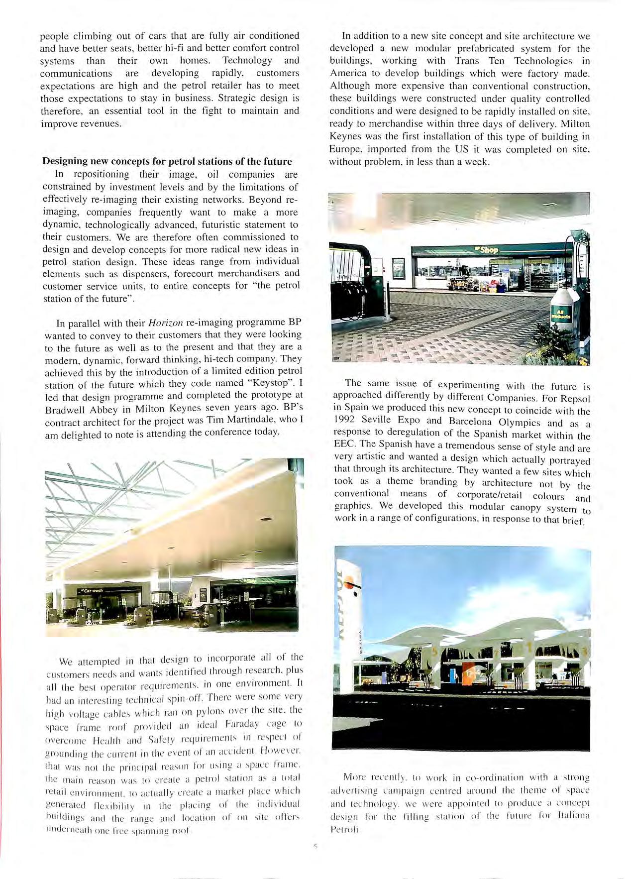
We a tt e mpt ed in that des ig n to in co rp o ra te all of th e c us to me rs nee ds a nd wa nt s id e ntifi ed throu g h rese arch. plu s a ll th e best o pera to r require me nt s. in o ne e n vironm e nt It had a n inte res tin g tec hni ca l spin -o ff Th e re we re so me ve ry hi g h vo lta g e ca bl es w hi c h rnn o n py lo ns o ve r the s it e. th e s pac e fra me ro o f pro vid ed a n id ea l Fa rad ay cage to o ve rco me Hea lth <in d Safe ty re quire me nt s 111 res pec t of g ro un cl in a th e cu rre nt 111 th e eve nt of a n acc id e nt H owe ve r e tha t was no t the pri nc ipa l 1·e aso n for usi ng a .s pac e r1 ·a rn e the ma in reaso n w as to c re a te a pe tro l s ta ti o n a'> a total re tai l e n viro nme nt. to ac lll a ll y c re a te a rnar ke l p lac e w hi c h ge ne rated fl ex ibil it y in the plac in g of th e indi vidu a l bui ld in gs a nd the ra nge a nd locat io n of on s it e und e rn eath one fr ee s pa nni ng roo f
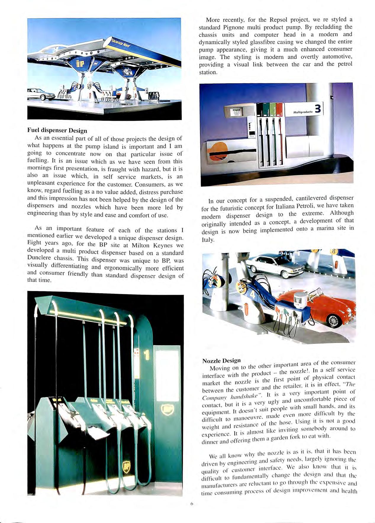
The same issue of experim e nting with the future is differently by different Companies. For Repsol 111 Spam we produced this new concept to coincide with the 1992 Seville Expo and Barcelona Olympics and as a response to deregulation of the Spanish market within the EEC The Spani sh have a tremendous sense of style and are very artistic and wanted a de s ign which actually portrayed that through its architecture. They wanted a few sites which took as _ a theme branding by architecture not by the conventional mean s of corporate/retail colours and graphics. We developed this modular canopy system t work in a ran ge of configurations , in respon se to that briefo
M()re rece ntl y. to wo r k 111 co ordination w ith a strong ad ve ni s 1n g campai g n ce ntre d around th e th e me of s pac e and tec hnol og y. we we re app o int ed to produ ce a conc e pt de s ig n for 1he fillin g s tat io n o f the fulur e for lt a liana Pe trol i
Fuel dispenser Design
As an essential part of all of those projects the design of what happens at the pump island is important and I am going to concentrate now on that particular is s ue of fuelling. It is an issue which as we have seen from this mornings first pre sentation, is fraught with hazard, but it is also an issue which , in self service m a rkets, is an unpleasant experience for the customer. Consumers , as we know, regard fuelling as a no value added, distress purchase and thi s impression has not been helped by the de s ign of the dispensers and nozzles which have been more led by engineering than by style and ease and comfort of use
As an important feature of each of the stations I mentioned earlier we developed a unique dispenser design. Eight y ears ago, for the BP site at Milton Keynes we developed a multi product dispenser based on a standard Dunclere This dispenser was unique to BP, w as visually differentiating and ergonomically more efficient a nd consumer friendly than standard dispens e r desi an of that time. 0
More recently, for the Repsol project , we re styled a standard Pignone multi product pump. By recladding the chassis units and computer head in a modern and dynamically styled glassfibre casing we changed the entire pump appearance, giving it a much enhanced consumer image. The styling is modern and overtly automotive, providing a visual link between the car and the petrol station.
In our concept for a suspended, dispenser for the futuri stic concept for ltaliana Petroh , we have taken d desi an to the extreme. Although modern 1spense1 o II t nded as a concept a development of that ona111ay111e ' 0 b · 1 ·mplemented onto a manna site 111 design is now emg Italy
Nozzle Design
Hnt area of th e co ns um er to th e other 1mpo1 ' ' Mov111g on 1 ozz le 1 In a self serv ice . h I product tie n mterface wit t the first point of physical con ta c t market the nozzle is d .1 et·Jil er it is in effect , " The I tomer a n ti e I ' ' between t 1e c us ,. 1 a very imp o rtant point of I t is ' Co111ponv wn · · 1 aiid un comfo rt able pi ece or · · ve ry ug Y ' contact , but it is a . . pi e w ith s mall ha nd s and it s It do es n t s uit peo ,, eq uipm en t. de e ven more dill 1c ult by the d ·r·· l t mano e uvre. ma 1 lieu t o . f th e hose. Us mg 1t 1s not a good I t id resistance o I we1g 1 ai 1.k e in v itin g so me boc y aro und to lt 15 a lm ost 1 expe ri e nce. · ·de n fo rk to ea t w ith. dinner a nd offe rin g th e m a gai
I tl e no zz le is as it is. that it ha s be e n We a ll know wiy 1 · ' , · 0 and safety needs. large ly 1gnonng the dn ven by e n a111ee 1Ill_, 0 r r inte rfac e. We a ls o know that 11 1s quality o l c uston c I , ,· I f id·rnie ntall y c han ge th e c es 1gn cmd that the chfhc u t to ui ' · I' t· ei·-· ire re luctant to go throu g h th e ex p e ns1 ve and 111 anu ac u1 ·' ' S LII11111 o pro cess of design 1mprnv e rnent and h ea lth tim e co n o ' ·
6
and safety approval. However, that should not be a reason to avoid investigating the opportunities to significantly improve the cu stomer experience through innovative design.
It doesn ' t help, of course , th a t so many car models have their fuelling intake positions in many different places and that people are not always aware when they pull up to the island, which side their car fuels , or even how to dock in relation to the dispenser. This may a ll change in due course as the next presentation by Autofill will demonstrate. In the future , robotic fuelling may well solve many of the problems but in the meantime existing nozzle design poses significant problems to the consumer and doe s not enhance th e image of the retailer.
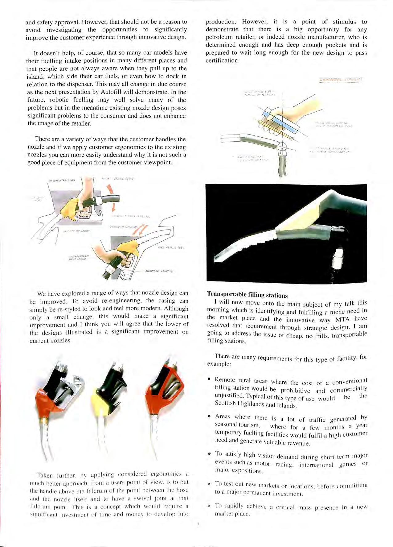
There are a variety of ways that the customer handles the nozzle and if we apply customer ergonomics to the existing noz zles you can more easily understand why it is not such a good piece of equipme nt from the customer viewpoint
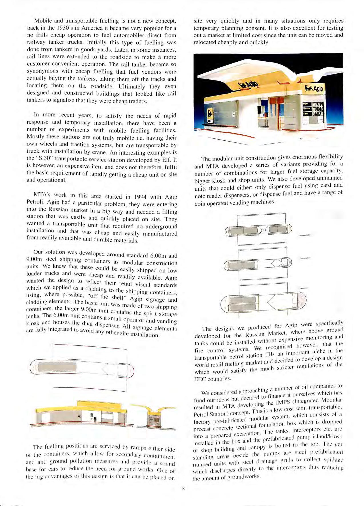
production. However, it is a point of stimulu s to demonstrate that there is a big opportunity for any petroleum retailer, or indeed nozzle manufacturer, who is determined enough and has deep enough pockets and is prepared to wait long enough for the new design to pass certification.
We ha ve ex pl o red a ra nge of wa y s th a t no zz le de s ign ca n b e impro ve d. To a void re-en g in eerin g , th e cas in g can s impl y be re s tyl ed to look a nd fe e l more modem. Although o nl y a s m a ll c han ge , thi s wo uld mak e a s ig nificant impro ve me nt and I think yo u w ill agree that th e low er of th e d es ig ns illu strat ed is a s ig nifi ca nt improv e ment o n c urre nt nozz les.
Transportable filling stations
I will now move onto the main subject of my talk thi s momrng which is identifying and fulfilling a niche need in the m arket pl ace a nd the innovative way MTA h a ve res_olved that require ment through strate gic de s ign. I am gorng to addre ss the iss ue of cheap no frill s tran s portabl e filling station s ' '
There are many requirem e nts for this type of facility , for ex a mple:
• Re mo te rura l areas where the co st of a conventional fI!hn g station would be prohibitive a nd commerc ia lly UnJu s.t1f1ed,- Typical of thi s typ e of u se would be th e Scotti s h H 1ghl a nd s a nd Is la nd s
• Areas where th e re is a lo t o f traffic g e nerated by seaso nal to uri sm . w he re for a few month s a ye ar temp orary fu e llin g fa c iliti es wo uld fulfil a hi g h c u sto m e r need a nd ge ne rate va lu a bl e re ve nu e
• To sat isf y hi a h vis it o . d d 1 1 b · 1 e man c unn g s iort event s s uc h as moto r rac in g , inte rn a ti o n a l m aJo r ex pos iti o ns
Tak e n fur ther. by app ly ing co ns ide re d e rgo no mi cs a m uc h be tte r a pp roac h fro m a use rs po int of v iew. is to put th e han dl e abo ve the ful c ru m of the po int be twe e n the hos e a nd th e nou le its e lf and to ha ve a s wiv e l Jo int a t tha t fu lc rum po int. Thi s is a co ncep t w hi c h wou ld require a in ves tm e nt of time a nd mo ne y lo d eve lop in to
te rm major ga m es or
• To tes t o ut new ma rke ts o r loca ti o ns. b efo re co mmittin g to a maj or pe rm a ne nt in ves tm e nt.
111 To ra pidl y ac hi ev e a c riti ca l mass prese nce in a new ma rke t pl ac e
\i o;;.j v R:.cr;..&E rmsr AN5L E
7
E.RC.GNO!MC Cu\?EPT
rE := --E '.,,£"' >-·<: --r f. .<._£
,,,: -;; -;s:= ;.. '..!'.
Mobile and transportable fuelling is not a new concept, back in the l 930 ' s in America it became very popular for a no frills cheap operation to fuel automobiles direct from railway tanker trucks. Initially this type of fuelling was done from tankers in goods yards. Later, in some instances, rail lines were extended to the roadside to make a more customer convenient operation. The rail tanker became so synonymous with cheap fuelling that fuel vendors were actually buying the tankers, taking them off the tracks and locating them on the roadside. Ultimately they even designed and constructed buildings that looked like rail tankers to signalise that they were cheap traders.
In more recent years , to satisfy the needs of rapid response and temporary installation, there have been a number of experiments with mobile fuelling facilities. Mostly these stations are not truly mobile i.e. having their own wheels and traction systems, but are transportable by truck with installation by crane. An interesting examples is the "S.30" transportable service station developed by Elf. It is however, an expensive item and does not therefore , fulfil the basic requirement of rapidly getting a cheap unit on site and operational.
in this area started in 1994 with Agip Petroh. Ag1p had a particular problem, they were entering mw the Russian market in a big way and needed a filling station that was easily and qtii"ckl I d ·t TI ' y p ace on s1 e. 1ey wanted a trans1Jortable u ·t tl · n1 1at required no underground rnstallat1on and that w · I · ' as c 1eap and easily manufactured from readily available and dtii··ible t . 1 • ma ena s.
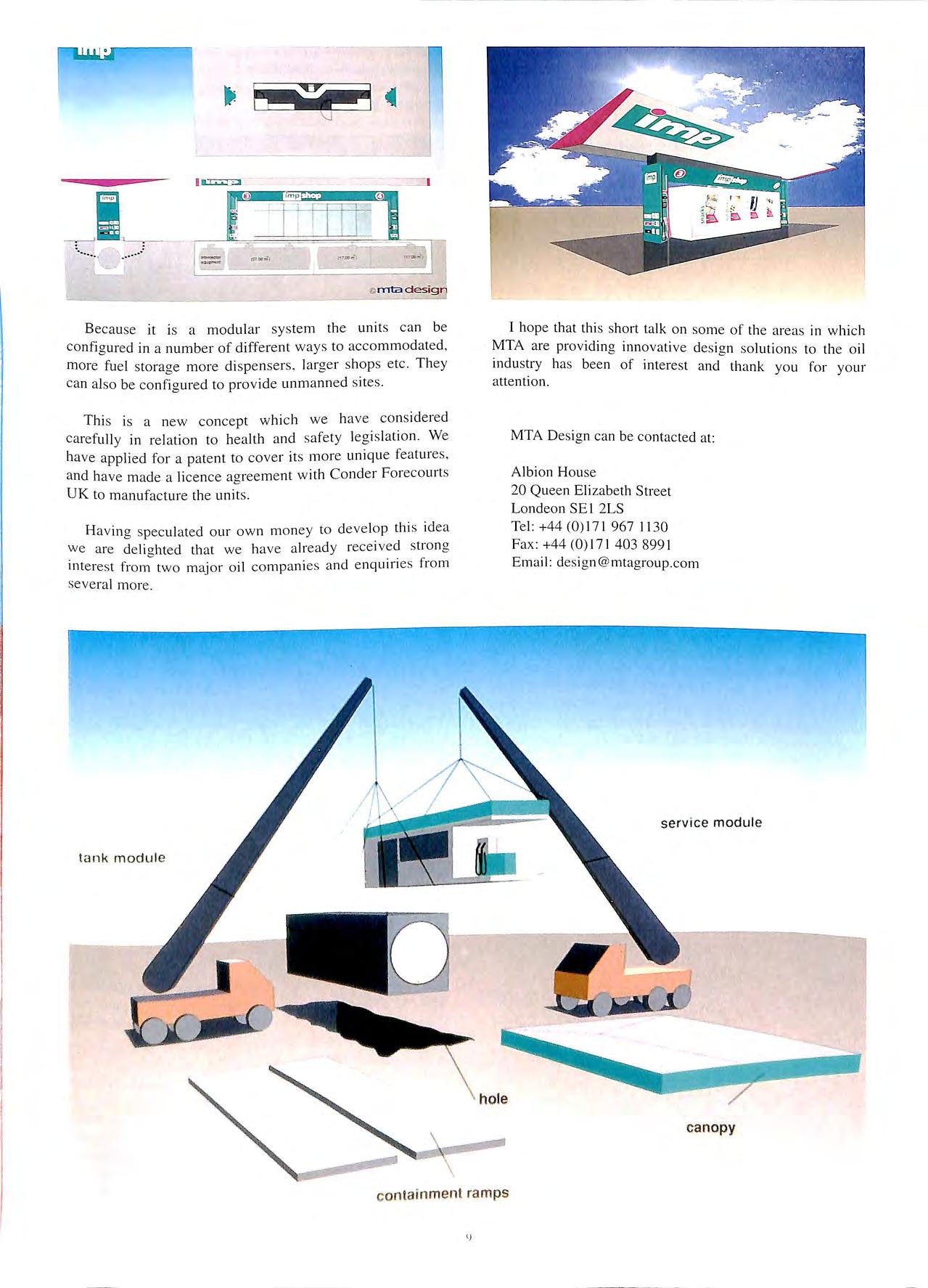
Our solution was developed ai·o d d d 6 OO d un stan ar . m an 9.00m steel sh1pprna conta 1 · 0 ne1 s as modular construction umts. We knew that these could be .1 1 . eas1 y s 11pped on low loade1 t1 ucks and were cheap and . d .1 • 1ea 1 y avallable Aa1p wanted the design to reflect th · · 0 · ell 1etall visual standards which we applied as a claddina to th 1 · Lls in" where possible " ff h 0 e s 11 PPmg con tamers , o' ' O t e shelf' Acr' ·a cladding elements. The basic un·t o 1P. s1onage and 1 was made of tw J · · containers , the larger 9.00m Lini·t . o s 11pprng contarns th · .· tanks. The 6.00m unit contains ·1 s 11' e sp111t storage ,, ;0 sk and house s the dual d' ' ma operator and vending 1\.1 • • 1spenser. All ·a are fully 111tegrated to avoid an 1 _ . _ 51 onage elements Y ot iei site rnstallation.
site very quickly and in many situations only requires temporary planning consent. It is also excellent for testing out a market at limited cost since the unit can be moved and relocated cheaply and quickly.
Th e fu e lling po s ition s are se r v iced b y ramps either side of the containers. which allow for seco ndary c 0111 '1·rnment and anti ground pollutlon m e asures and provid e a s ound bas e lor ca rs to red uc e th e nee cl for grnuncl works. One of the big advantag es of this d es ign is that it can be plac e d 011
The modular unit construction gives enormous flexibility and MTA developed a series of variants providing for a number of combinations for larger fuel storage capacity, biaaer k.iosk and shop units. We also developed unmanned that could either: only dispense fuel using card and note reader dispensers , or dispense fuel and have a range of coin operated vending machines.
for A ai were specifically
The designs we produced 0 pi ·e above around R Market. w 1e1 ' b developed tor the us s ic1n " ,e monitorina and b . t II d without expensn b tanks could e ms a e cl however that the We recoarn se ' fire control sys.tems. 0 portant niche in the l I ration fills an im ' transportab e petro s ' · cl cl ·c1ed to d e ve lop a design · 11· 11arket an ec i world retail Ju e ll1g 1 ' 1 t ··cte r rea ulation s o1 th e which would satisfy the muc i s 11 "" EEC countries.
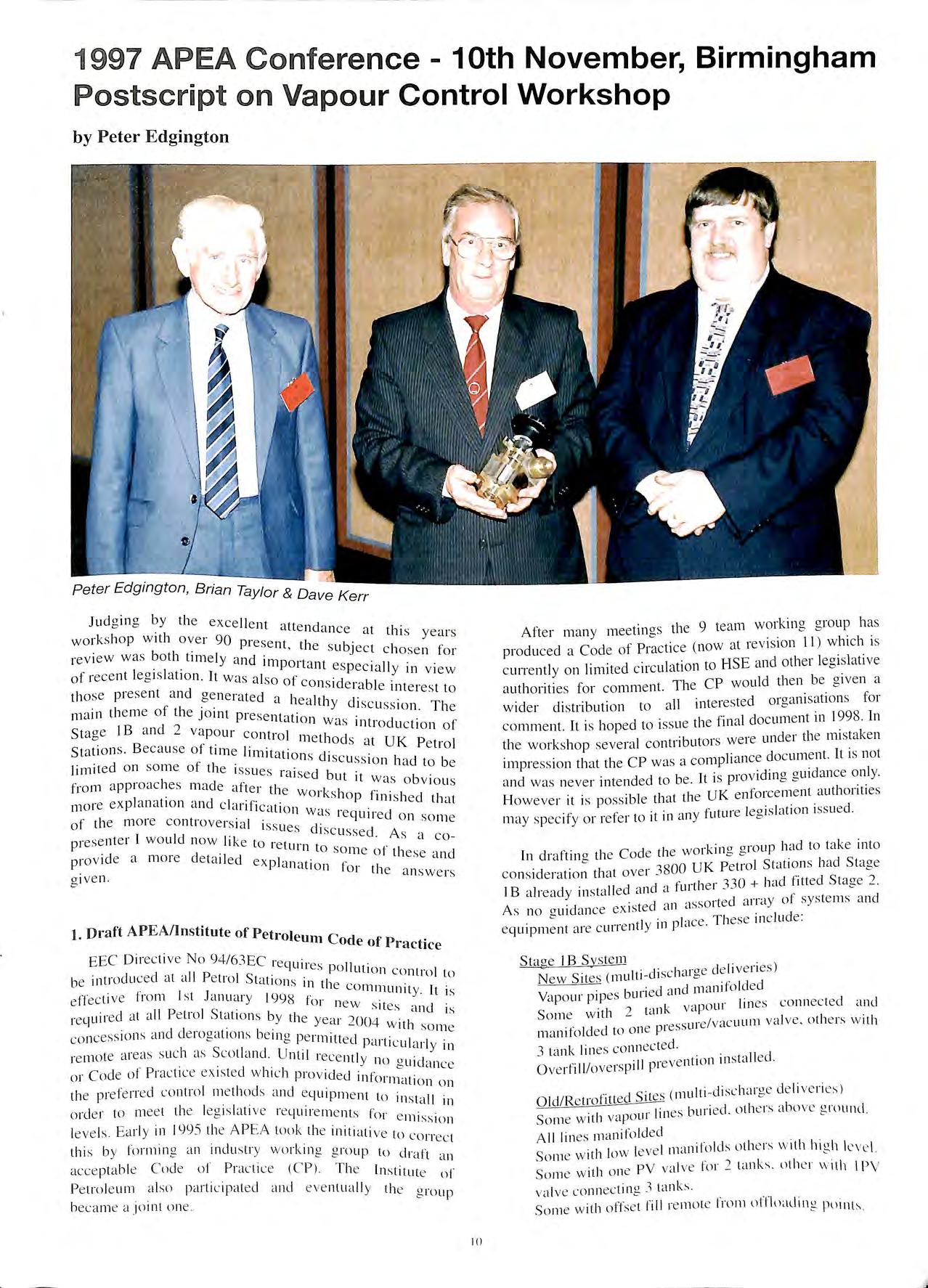
_ iib e r of oil companies to cl ·oachll1" a nu1 We cons1dere appi 0 ·e 1 ·t ourselves which ha s cl id ecl to l!nanc fund our id eas but ec 1 CMPS (lntearatecl Modular . T'A cl eloprna ti e o resulted 111 M '"' ev 0 1 w c ost se mi-transportabl e , . ) e pt This 1s a o Petrol Station co ne · 1 ste m which co nsists of a t· b.· tee! modu ,u sy factory pre- a i ica f cl · tion box which 1s dropp e d c t1on a l oun d precas t co nc1ete se _ Th e tank s. int e rce ptors e tc. are · · a red e xcavation.
· ·] I/I · k 111to a p1 e pc I ·efabricate cl pump 1s anc .;. 10s · 11 cl tl e box and ti e p1 ' ms ta e 111 1 ' · bolt e d to th e top The car ·1d· cl C"1110 ]J)' IS or s hop bui rn g an ' · I , , t ·· , ·c1 th e pump s me stee pi e c1111Lc1teJ stanclina areas bes 1 e I\ ·1 · 0 · 1 t e l draina ge !!rI ll s to co e el s p1 la g l' r·1111ped unit s w it 1 s e v ' · 1 clii·ec tl y to th e mtercept m s thus which disc 1,u ges L th e amount of gro und wo rk s.
lj) I
-:
I
Because it is a modular system the units can be configured in a number of different ways to accommodated, more fuel storage more dispensers , larger shops etc. They can also be configured to provide unm anned sites.
Thi s is a new concept which we have considered carefully in relation to health and safety legislation We have applied for a patent to cover its more unique features , and have made a licence agreement with Conder Forecourt s UK to manufacture the unit s
Having sp eculated our own money to develop this idea we are delighte d that we have already received strong inte re s t from two major oil com pani es and enquiries from seve ral more .
I hope that this short talk on some of the areas in which MTA are providing innovative de s ign solutions to the oil industry has been of interest and thank you for your attention.
MTA Design can be contacted at:
Albion House 20 Queen Elizabeth Street Londeon SE I 2LS
Te l: +44 (0)171 967 1130 Fax : +44(0)171 403 8991 Email: des ign@mtagroup.com
I 11 ·······
·
ta n k modul e
lJ
service modul e c anopy containment ramps
November, Birmingham
P os t sc r ipt o n Vapour Control Workshop
 by Peter Edgington
Jud g ing by th e excellent att e 11d·1nce t I · ' a t 11 s year s work s hop with over 90 present tl b. ' 1e su J e ct cho s en for revi e w wa s both tim e ly and imp t 1 01 ant e sp e cially in view of re ce nt le g 1s a t1on. It wa s al s o of ·d const e rabl e rnterest to tho s e pre s ent and gen e rated a h e altl d. · · f 1 · • 1Y 1s cu s s1on The 111 a 111 th e me o t 1e JOrnt pre se ntation .' d 2 wa s 111troduct1on of Stage I B an vapour control m e t] d · B , · 10 s at UK P e trol Stations. e cau s e o1 tun e Itmttat' d. ' ion s is c u ss 1o n had to be 111111 ted on s ome of th e iss u es rai se d b . I ' · ut tt wa s obvi o us from approac 1es mad e a f ter th e ·k . 1 .' I · w o i s 1op f1n1 s h e d tl t 1110 re exp anat1on and clarifi ca ti o 1 a n W d s t e qu1red o n s o of the 11101 e c ont1 ov e 1s tal i ss u e 1 • m e · · s c tsc us se d As Pres enter I w ould n o w lik e to re t . · · a c o u1 n to s om e o f th . . d pro v id e a more d e tail e d ex phinti f e se an ' ' on or th e an s w e rs gi ve n
1. Draft A P E A/I nstitute o f P e t roleu C 1 111 oc e of Pr a c tice
EEC Direc ti ve N o 94/6 3EC re quires 11 . • cl II p o ut1on c ontrol to b e intro du ce a t d Pe t1 o l St a ti o n s in tl I 1e co rnrnuntt y It is effec tiv e 1To m s t J a nurn -y 1998 fo r . · , n ew Sites a nd is re quire d at dll P e t1 o l S tati o ns b y th e "ea r 2 (l04 · I I · J w tth so m e co n cess io ns a nc c e t o ga tt o ns b e 1n o p e rmi tte d . • • b p ai t1 c ularl y in re m o te ai e<1s s u c h .1s Sco tl ,111d. Until rece ntl y . . . . . . n o g uid a nc e o r C o d e o 1 Prac ti ce ex isted w hi c h pro v id e d inf'c ll m <1 t1 o n o n th e pre fe rre d co ntro l m e th o d s a nd e quipm e nt to · II 1ns ta 111 o rd e r to m ee t t he leg 1s la twe re quire m e nt s foi · e · · m1 ss 10 11 leve ls Ea rl y in 1995 th e A P EA to u k th e initi a ti ve to co rrec t thi s b y for min g a n indu s tr y w or k in g g roup to dr a ft a n acce pt a bl e Cod e u l P rac ti ce (CP ) Th e In st itute nf Pe tro le um a lso pa rti c ipa ted a nd eve ntuall y t h e g roup beca m e a j o int on e.
· ] 9 te 1111 w orkin ° a roup ha s Aft e r many m e etm gs t 1e ' b "' produ c ed a Code of Practi ce (no w at re v1 s1on 11 ) w hi c h. 1s · 1 · t HSE and othe r Je a is la t1v e curre ntly on hm1ted circu a t1on o ' 0 Th CP wo uld th e n be 0 ive n a authont1es for comment. e "' ·c1 c1· .b t' t all 1·11te re s te d oraa ni sa t10n s fo r wt er is tn u ion o < • 0 comm e nt. It is hop e d to iss u e th e final docum e nt in 1998. In ' b · Lm de r th e mi sta ke n the work s h o p se v e ral contn uto1 s w e1e . . 1 a 1ce do c um e nt. It 1s not 1mpress 1on that the CP wa s a c omp 1, 1 . b It · pi·ov idin a a u1d a nce onl y. and w as n e ver mte nd e d to e . ts o 0 H 'bi tl t th e UK enforce m e nt auth o ntt es o w eve r 1t 1s po ss t e rn d . . . · t' itLii·e lea is la t1 o n iss ue m ay s p ec ify or ref-e r to 1t 1n a ny L "'
·
l d f I c d e t l1 e n ro rkin a CJ l'OU(J h ad to ta ke into n ra -rm g t 1e o o o 38 00 UK P e tro l St a tt o ns ha d Stage co ns id e ra t io n th a t ove r d f tl e r 33 0 + ha d titt e d St age 2. I B alrea d y m s tall e d an a ui 1 , , , . . . . d . 1 a sso rte d a rra y of sys te m s a nd A s n o a u 1d a nce ex 1s te a t ' · 0 1 · I· ce Th ese in c lud e: e quipm e nt a re c urre nt Y 111 P cl ·
Sta ge IB S vs te m 1 l · cl· I a rae de 1ve n es N ew Si tes (multi isc le 0 • · cl a nd 111 a ntf o ld e d Va p o ur pipes bu11 e < " • ? • k va iJo ur Itn es co nn ec ted <111d S o m e w ith td n 1 " ess ure/vac uum Vdl ve. o t 1e 1s w it h rn a n ifo ld e d to o ne P1 3 ta nk lin es co nn ec te d. . Ove rfi 11/ove rsp i 11 p reve ntion tns ta Iled
(:· d S t'tes ( mul t i-d isch a rge de li ve ri e s) Ol d /R e tro 1tte · 1 Llr lin es buri ed. ot he r s a bo ve g roun d. So me w it 1 va p o · A ll lin es rn a ni fo ld e d S ·ri 10,., leve l 111 a ni fn lds o th e rs w it h hi \! h leve l. o m e w 1 1 " S i I 0 11 e P Y va lve for 2 ta n b. nth e r w ith I PV o me w 1 1 va lve co nn ec tin g .1 ta n ks So m e w ith offse t fill re m ote fro m pu in h
1997
A PEA Co nf erence -1Oth
Peter Edgington, Brian Taylor & Dave Kerr
J()
Stage
System
Most have forecourt pumps modified or fitted with vacuum pump return (active system) in the vapour line. A few fitted with the earlier 'non-assisted' (passive system) vapour return.
These are a few of the combinations which exist. The dilemma facing the Working Group was should they specify the best technical solution which in their opinion would be buried manifolded vapour pipes, pipe sizes specified, preferred number of PV valves for Stage IB listed, overfill/overspill prevention mandatory and an active system for Stage 2, or make the recommendations broad yet technically acceptable to encompass the maJonty of systems which currently exist. The Working Group chose the latter approach on the basis t hat the Code could always be modified at some future date to exclude those systems which were subsequently proven either obsolete, technically unacceptable, unreliable, inefficient or health problems. Financial benefits are also vitally important to all Petrol Station owners and operators but this should not become the overridino consideration in selectino • 0 0 or systems. The EEC legislation is primarily Intended for emission (pollution) control. It was for these reasons that the working group favoured adoption of the closed balance system for both Stage l B and 2 with vapours collected in the delivering road tanker and transported back for disposal at a main terminal or refinery. The closed balance system was first introduced in North America in the early l 970's and is now installed in the Far East. Australasia. Middle East and Europe. Thousands of these systems are now in service with exceptional reliability and safety.
One of the criticisms made during the discussion was why systems or devices aimed at product cost/saving such as Petro-man. Vapa-Sava and soft fill devices were omitted from consideration or reference in the Code. The answer is they were considered but the Working Group could not include them as this was tantamount to approving them. These devices have yet to prove themselves in terms of experience, reliability and safety. The WG does not dispute that these systems/devices may produce worthwhile financial savings but it cannot include products hy hrand name. Furthermore in a Code of this type it is impossible to include every system or device that is likely to be developed in the future otherwise it would have to he constantly updated and revised. The APEA/IP no wish to do this and furthermore does not have the organisation to do so even if it wanted to. To overcome this problem and not wishing to stifle or preclude new developmenh. the Working Group decided to include appropriate general wording al selected points in the Code permitting the use or such devices provided certain criteria were met. Should a system or equipment supplier wish to have his products in the future the following acticJn is recommended.
• C()nvince the purchaser/user of its ahility to perform as per specification \\hi lst dernonstrat ing that it is re. reliable and cost effective.
• Not i11t · -1· · · I I I e1 ere adversely with the operation ol l ll' c oseL h;d;inu· 'Yste111 into which it 1ns1allcd
• Be compatible with other components in the system. For example some of the cost saving systems or devices now being promoted increase tank pressures. Some automatic tank gauges and forecourt pumps may be pressure sensitive and operation could be adversely affected.
• Obtain acceptance and agreement from the local licensing authority.
2. Emission Measurement
Checking whether a vapour control System is effective in service is extremely difficult as there is no simple method for determining efficiency. As the purpose of the EEC legislation is Pollution control this means determining emission levels at those points in the system where vapour release to the atmosphere is likely to occur. Generally this means measurement at vent stack outlets.
The methods which are available are either difficult to perform or require special equipment and are complicated, time consuming and expensive.
Some of the methods that have been used to date include:
• collecting vapours emitted over a specific time in special bags placed over vent outlets. These are then sealed and returned to a laboratory for analysis for contents.
• Using special probes or gas detectors to take stack samples and feeding these to either on-site analysers or returning them to a laboratory for analysis.
The UK Institute of Petroleum and USA ASTM both publish books of test methods which include the above. Guidance from either of these organisations should be sought if further information is required.
Not withstanding the above comments it is now generally accepted based on several years use with Vapour control systems worldwide that providing they are properly installed serviced and maintained the following are possible.
(a) Stage IB closed balance systems will reduce emissions to the atmosphere by at least 9()C,4.
(b) Stage 2 active systems will reduce emissions to the atmosphere hy at least 95o/r.
3. Lead Uptake in Mixed Vapours
The systems recommended in the Draft Code permit mixing through manifolding of vapours from leaded and unleaded gasolines. The Code also recommends a separate vent system for diesel fuel.
Concern was expressed that this permitted m1xmg of gasoline grades might lead to contamination problems when the product was subsequently recmered. Work by the Petroleum Industry has shown that the amount of airborne lead in collected vapours is extremely low and when the product I'- en'ntually reco\ered the level of lead in the
ll ' / I '. Ii I. I 1 · , ,
2
II
liquid gasoline is well within the permitted tolerance for lead in unleaded gasoline which is 0.01 lg/I max. This figure has been established as an acceptable level following work by the Petroleum and Automotive industries. For further information refer to the IP Code of Practice for the introduction of unleaded gasoline.
Before anyone queries this figure it is worth pointing out that most unleaded gasoline grades contain trace lead. This is because when the switch to unleaded gasoline was made, a completely new and dedicated distribution system to transport it was impossible to achieve bearing in mind the complicated and diversified system of transportation that is used plus the additional cost that would be involved. Existing systems had to be used and no matter how much cleanino and flushing is perfmmed lead "pick-up" will always Over years of use this pick up will decrease but trace lead is always likely to be detected in unleaded gasoline samples.
4. Testing of Forecourt Pumps ti Flow Tests
The majority of Stage 2 systems now being installed are of the active type and involve forecourt pumps modified or fitted to take a vacuum return system for the vapours. These pumps incorporate an electronic system which controls the return vapour flow in relation to product dispensed. Because of their design these pumps can be readily checked for efficiency without the need to pump gasohne i.e. dry tests can be performed. At present the only requires to be done when the system is first mstalled. However m some European Countries re-testino is now required every three years. Several contributors feh that in UK an annual test should be conducted. This will be considered before the Code is finally issued.
4.2 Vacuum Pump Pressure Testing
One contributor reported problems in com I · · h p ymg Wit cun-ent reqmrements to pressure test comp! ete vacuum pumps_ at a pressure of 15 PSI. Invariably failures were occun-mg. This pressure appeared unduly h · h 1 . 1g compared with the norma workmg pressure for this t f · ype o pump. Such high pressmes are usually adopted c d 101 casmg tests only in or er to prove them for u. · · Th se 111 explosive atmospheres. 1s 1s the procedure adopted · · p t 1 t · or gantry meters m e ro eum e1mmals and it was rec d · f . . ommen ed that the Institute o Petrnleum or mdividual manufacturers be contacted for guidance on pump ' 1s pro em.
4.3 Efrlormance Testing of Passive Systems
Unlike the active system no simple method · t cor ff ex1s s 1• Checking the e 1c1ency and pe1formance of a p· .· dSSIVe system without mstall_mg equipment. Whilst the amount of product dispensed mto a vehicle is accurately metered at the forecom1 and known. there is no comparable method of measuring the return vapour flow to the underground storage tank. To do so would mean installing a vapour meter or. similar de:ice _in the 1:eturn line with the added complicat10ns of cahbrat10n. mamtenance and cost. Also meters of this type tend to be designed for development and research application and not as a permanent installation in a working environment. This is obviously a subject which requires further investigation to see if a viable alternative can be found.
5. Tank Dipping and Split Deliveries
Installing a vapour control system of the closed balance type results in substantial pressure being generated at some stage in both the Road Tanker compartments and receiving underground tanks. Any operation which requires access either for tank dipping, inspection or any other reason is therefore potentially hazardous and will simultaneously release vapour to the atmosphere.
The Working Group have therefore provided guidance in the Code on precautions which should be adopted when dipping tanks for contents measurement and the procedures which should be followed. These include:
(a) No manual tank dipping permitted whilst offloadino product from Road Tanker into underground tank. completion of delivery allow tank pressure to return to atmospheric before opening any hatches or dip points.
(b) No manual tank dipping permitted whilst vapour hose remains connected between road tanker and underground tanks. This applies to dips both before and after delivery. Tank pressure must be released and vapour hose disconnected before any hatches are opened.
(c) Dipping for split deliveries where contents of a road tanker compartment maybe discharged into more than one underground tank at one site or split between two or more petrol stations maybe earned out provided (i) the operation can be performed safely and (ii) the precautions recommended in (a) and (b) above are adopted.
To be completely safe and after releasing tank pressures before dipping, the working group supported the idea of allowing a set time period to elapse before dipping depressurised tanks. Although not specified in the Code this would appear to be a sensible precaution.
Tank dipping and split deliveries are not really compatible with vapour containment and return systems. As an alternative the petroleum industry is moving towards the concept of a "sealed compartment" delivery in which no tank dipping is permitted, and the contents of the road tanker compmtment irrespective of level is fully discharged into underoround tanks at a petrol station. This concept b requires the tanker compartments to be loaded through an accurate and reoularly calibrated meter preferably of the positive displac:ment type at the loading terminal and for the road tanker contents to be "sealed'' thereafter until discharge takes place. This concept is now being introduced in the UK and appears to be gaining acceptance. Positive displacement meters are now the industry standard for measuring fuel loaded at terminals and have an extremely good record of accuracy and reliability. In addition they are regularly checked and calibrated. The alternative is to fit either a tank gauge in each vehicle compartment or a delivery meter in the road tanker. This has been attempted in the past but has proved unsuccessful due to L'ost. system inflexibility. and the fact that no Conrnanv \1 1,. \' t • '·' ·Ct a tank gauge which will stand up to the of road tanker deliveries. Furthermore if such a syslt'n; was ever perfected it would raise a further 1wohlet" .1,. tl . · 11 '•'
1\t'L'
systems of measurement would then exist between road tanker loading at a bulk terminal and petrol delivered to the motorist. Variations between the three namely P.D. meters, road tanker gauges/meters and petrol station tank gauges/pump meters would be inevitable and trying to reconcile differences would create a major difficulty.
6. PressureNacuum Vent Valves (PV)
On a multi tank vent system in which individual tank vent lines feed into a common manifold sizing of the spur lines and manifold is extremely important in order to prevent excessive back pressures from building up. As a guide for a lOOmm (4") return to the vapour connection point. Obviously there are many variations in practice but it is always better to over estimate spur line and common manifolds size if back pressure problems are to be avoided (see section 7). These can have serious consequences upstream causing tank over pressures to occur and product crossover in vent lines from one tank to another.
To date pressure/vacuum valves have been designed for vertical mounting in tank vents at the highest point. One contributor queried whether horizontal mounting was possible where space restrictions could make vertical mounting difficult. As most PN valves are <lesioned for b vertical application , mounting in another plane would probably require complete redesign of valves. This is a s ubject which should be discussed with specialist P/V valve manufacturers if s uch a solution was required.
7. Operational Experience to Date
A s Stage 1B systems become installed problems are alre ady ari s ing mainly as sociated with items of equipment or deficiencie s in s ys tem de s ign. Some examples of these are:
(a) Vent spur and manifolded lines incorrectly sized. This creates back pressure build up forcing fuel across over through tank vent lines into other tanks. See previous comments on this subject.
(b) Pressure/vacuum valves unsuitable for operating conditions. Cases have occurred of valve chatter, internals sticking, corrosion and incompatible materials.
(c) Road Tankers converted for vapour return found to leak during deliveries. This mirrors experience in the USA when they first converted vehicles for vapour return some years ago. They had to introduce an intensive programme of leak testing before problems were overcome.
(d) Fittings damaged on discharge fuel hoses and vapour return yet off-loading still carried out with consequent leakage and spillage.
(e) Pressure/vacuum valves operating during a discharge with vapour return. This should be a clear warning to petrol station personnel that the vapour return system was not functioning correctly and that excessive pressure build up was occurring. The likely cause was restricted vapour return flow.
(f) Inadvertent cross coupling of fuel hoses. This indicates the need for clear marking of fuel hoses and for fuel and vapour return hoses to be either of different sizes or end fitting of different design.
All the above could have been avoided if greater care had been taken in system design , installation and choice of equipment and checking the system for satisfactory vapour flow before being put into service.
I cofn RE
g l'1tL rn t i o 11 11
DUCES
..
Petrol Dispensin g for the New Millennium
by Arne Myhrman, Vice President, Auto.fill AB.
Introduction
First of all I wot Id 1·k 1 1 e to thank the orgamser, the Association for Petroleu d E 1 . . . m an xp os1ves Admm1strat1on , for 111v1t111° me to this c 0 con 1e1ence and pres ent the worlds first commerc1al available system f . 1 11 . f 01 automatic re ue mg o cars.
The idea to the Autof II 1 f 1 d 1 1 system came up in 1984 in the ta1 o · t le eve opment of a t · . ' u omat1c teller machines (ATMs) 111 Eu1 ope who provided new ·ndustry world-w·d TI se rvices to th e bankin g I i e. l e goa l was to off . ·1 . the pro sp ect of in · · ei 01 comp,m1es d . . ci_easrn_g productivit y and th e refore a cos t 1e uct1on , 111 conjunction w·tl ff marketina tool. A t ·f.ll 1 1 1 0 enng them a new "' u o I las develotJed . ca r drivers need not 1 a p1ocess by which eave their ea· d · ' Is unng the retuellino process , pre se ntin g elements f 0 efficie ncy. · 0 co rntort , safety and
The Autofill Systen1
A utomated se r v ice stat io ns are w 11 k · e now n to m oto ri s ts. Pa y m e nt 1s mad e b y th e use of c1· c i e II paym e nt ca rd te rrrnnals OJ bank not e ac ce ptors H · · oweve1, until no w retu e ll11rn hd s bee n clone manual!)' as 1 ·t Il a . .- 1 . ·' · <Ss 1n ce t1 e birth of· motoring. Dirt y s lo w and in c onve ni e nt A t· r· 11 · · U 0 I I S th e first com111 e rc 1al system to offe r re fu e llin o w·tl m anua l int e rferenc e "" 1 lout an y
Th e c urre nt Autofi ll sys te m is th e third ge ne ration uf th e automat ic re fu e llin g sys te m that ha s bee n d eve loped Th e sys te m h as be ne fit e d from 13 ye ar s of te chni ca l
refinements , which have resulted in a viab le, dependable product that can b e mark eted internationally. The system consists of
(i) the refuelling automat. (ii) hydraulics, (iii) the payment terminal , (iv) a car kit (fuel cap and button).
t terminals a re 'off the The hydraulic s and the paymen tl at pump s and term ma ls f1 om a s helf ' products , m ea nm g 1 1 At r· 11 ' · _ b ed to ae ther w it 1 LI o I s vanety ot suppliers ca n e us 0 d the car kit are p1op11etai y products. The automat an 1 t , h followin a sect ion s t l e sys em s product s. In t e "" . . I cribecl cl I cl velopment ai e c es compo nent s an t l e ll e
Refuelling Process
.tl b)' us in o a credi t c ard ·t · refue llin g e 1 l e i , c The eh 1v e 1 s tdI 5 propriate te rm ma I. The button a l an ap , or by p1ess1n g a . 1 • and op e ns it 1 he no zz le 1s Automat lo ca tes th e 1ue Cdp I' 111·110 s ta1·1s , I th e re ue "" · ' · · mserted mt o th e tdnk dnc
1 5 co mpl e ted . th e s pout is 0 I ·due l 1n g " nee t 1e ' cl clos e d a nd th e Autornal re turn s I I th e fu e l oo 1 is w it lC 1awn Th e driv e r 1s 1nf or111 c cl b y a 1 ·estino pos 1t1on. . lo it s op11111a I '. "' I that th e re fu e llin g is comp le te d and display o n th e te 1mina · that he ma y drive a w ay.
Th e A ut omat is e quipp e d wit h a vapour rcc n ve r y nu n le . 1 cl ·11 th e fict that no one nee d s lo he ne ar l h1..· Th is. c oup e wi 1 ' 1 .- fJ . .. i·ea offe rs minimal ex po s ure tu a nd I SS U C ur re ue mg c1 ' • · t n es· T he vannur re cn ve r v svs tc rn \.\ nrk " h\ \\ 1\ nOXIOLI S lll · · t •
Presentation given at the APEA Conference, Birmingham, November 1997.
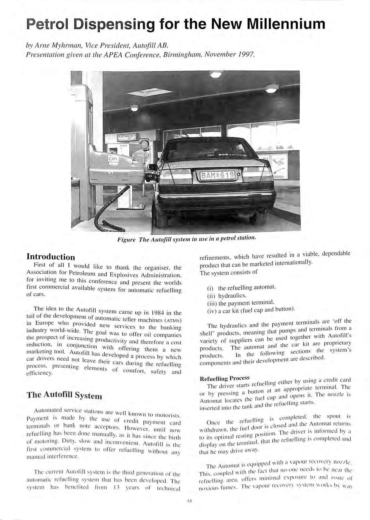
Figure The Auto.fill system in use in a petrol station.
1 :-::
of a fitting around the filling spout, which fits around the outer edge of the fuel cap. When the Automat connects to the car, this fitting is connected before the spout opens the valve in the fuel cap to start filling. After filling , the same valve is closed before the vapour tight connection is released. This way a complete recovery of the vapour is achieved.
Positioning
The positioning is based on microwave technology. The button is a signal transponder developed by Autofill. It is about the size of a coin, 3 cm in diameter and about 0.6 cm thick and contains electronic components including :
• central processing unit , • crystal for microwave frequency control, • standard, long life lithium battery.
The button is herm etically sealed with no service required. It is programmed with guidance information and reflects microwave signals emitted by the Automat. It can also be programmed to relay information about fuel selection or credit card payment data. The informationcarrying ability of the button can be continually improved to include vehicle identification information, payment , identification, parking systems, car wash equipment or for bridge or turnpike toll applications. Autofill is designed to refuel cars that have fue l caps on either side of the car, meaning that virtually all cars on the road can be serviced by the sys tem.
The button is mounted to the car by the use of strong adhesive. A paper template is placed over the fuel opening of the car and once it is co rrectly located , the button is attached as indicated on the template. The whole operation, including changing the fuel cap, takes less than one minute.
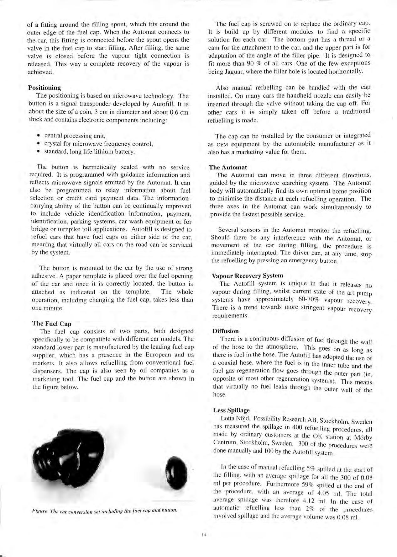
The Fuel Cap
The fuel cap consists of two parts, both de signed specifica lly to be compatible w ith different car model s. The standard lower part is m anufacture d by the leading fuel cap suppli e r, w hich has a prese nce in the European and us marke ts. It also allows refuelling from conventional fuel dispensers. The cap is also seen by oil companies as a marketing tool. The fuel cap and the button are shown in th e figure below.
The fuel cap is screwed on to replace the ordinary cap. It is build up by different modules to find a specific solution for each car. The bottom part has a thread or a cam for the attachment to the car, and the upper part is for adaptation of the angle of the filler pipe. It is designed to fit more than 90 % of all cars. One of the few exceptions being Jaguar, where the filler hole is located horizontally.
Also manual refuelling can be handled with the cap installed. On many cars the handheld nozzle can easily be in serted through the valve without taking the cap off. For other cars it is simply taken off before a traditional refuelling is made.
The cap can be installed by the consumer or integrated as OEM equipment by the automobile manufacturer as it also has a marketing value for them.
The Automat
The Automat can move in three different directions , guided by the microwave searching system. The Automat body will automatically find its own optimal home position to minimise the di stance at each refuelling operation. The three axes in the Automat can work simultaneously to provide the fastest pos sible service.
Several sensors in the Automat monitor the refuelling. Should there be any interference with the Automat, or movement of the car during filling, the procedure is immediately interrupted The driver can, at any time, stop the refuelling by pre ss ing an emergency button
Vapour Recovery System
The Autofill sys tem is unique in that it releases no vapour during filling , whilst current state of the art pump sys tems have approximately 60-'.0% vapour recovery. There 1s a trend towards more stringent vapour recovery requirements.
Diffusion
There is a continuous diffusion of fuel through the wall of the hose to the atmosphere. This <>oes on as 1 b · ono as there is fuel in the ho se. The Autofi ll has adopted the of a coaxial hose , where the fuel is in the inner tube and the fuel gas regeneration flow goes through the outer part (ie , opposite of mo st other re ge neration sys tems) Th. · is means that virtually no fuel leaks through the outer wall of the hose.
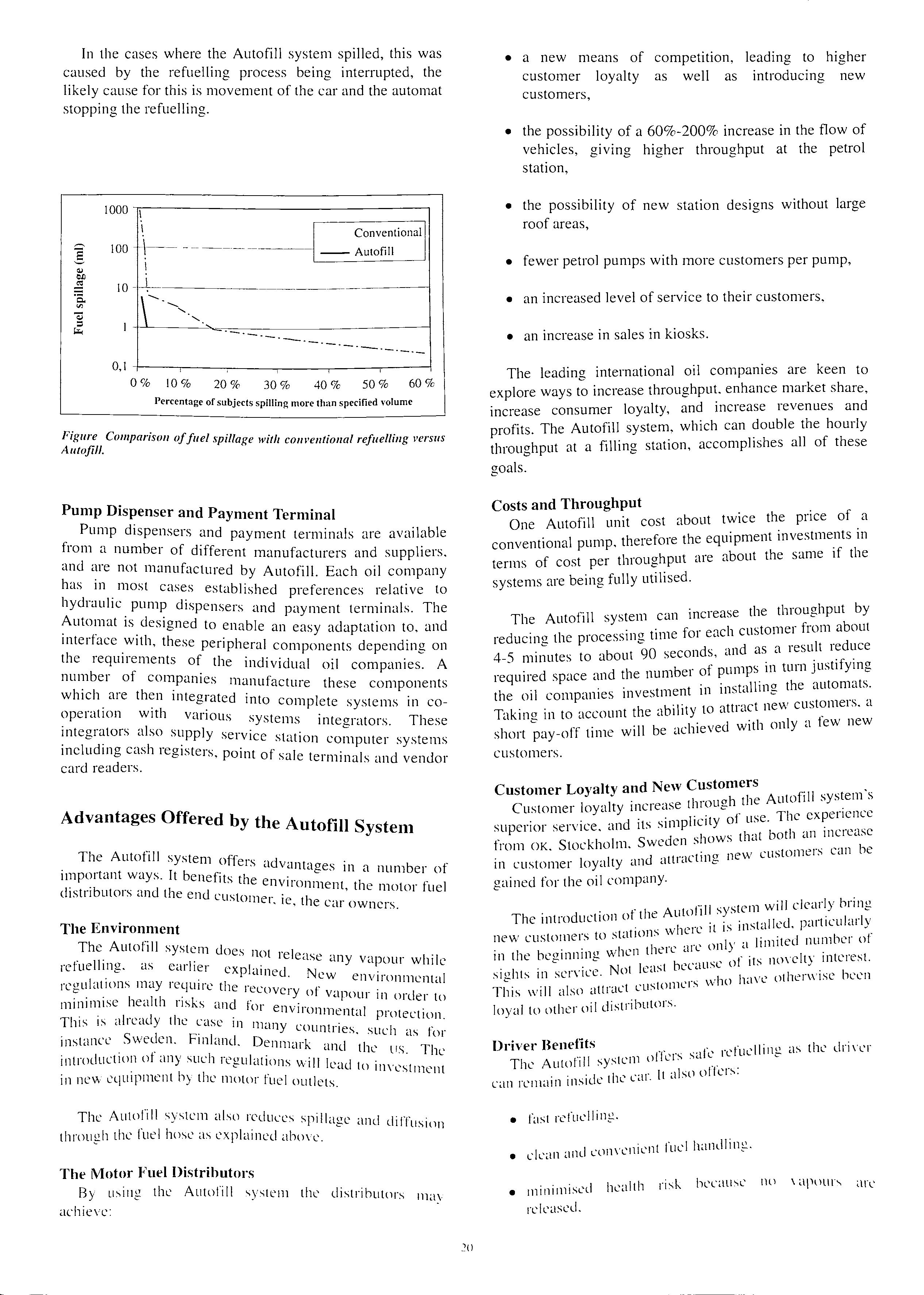
Less Spillage
Lotta Nojd, Poss ibility Research AB , Stockholm , Sweden has measured_ the spi llage in 400 refuelling procedures, all mad e by ordmary customers at the OK station at Morby Centrum , Stockholm , Sweden. 300 of the procedures were done manuall y and l 00 by the Autofill sys tem.
In the case of manual refue lling 5 % spilled at the sta rt of the filling , with an average sp illage for all th e 300 of 0.08 ml per procedure. Furthermore 59% spilled at the end of the procedure , with an ave rag e of 4.05 m l. The total average sp illage was there fore 4.12 ml. In the case of automat ic refue llin g less than 2% of the procedure s in vo lved spillage and th e ave rage vo lume was 0.08 ml.
. I t '', ·r lI \
19
Figure The car conversion set including the .fuel cap and button.
In the cases where the Autofill system spilled this was caused b th · f 11· ' . y . e u_e mg process being interrupted, the likely_ cause for this is movement of the car and the automat stoppmg the refuelling. 1000
• a new means of compet1.t1"on, I d" h" ea mg to 1gher customer loyalty as well as introducing new customers,
• the ?ossibility of a 60%-200% increase in the flow of giving higher throughput at the petrol stat10n,
• the possibility of new station designs without large roof areas,
• fewer petrol pumps with more customers per pump,
• an increased level of service to their customers,
• an increase in sales in kiosks.
Figure Comparison offuel s ·11 Autofill. pi age w1tli co111•e11tio11al refuelling 1•ersus
Pum D" p and Payment Terminal
Pump dispensers . d . from a n b an payment termmals are available um er of diflC and are not n . f erent manufacturers and suppliers, 1anu actured b A f" has in most Y uto Ill. Each oil company cases estabr ·h d hydraulic pump d" . . is e preferences relative to 1spensers ·md Automat is des· d · ' payment termmals. The · igne to enabl · interface with th . e an easy adaptation to. and ' ese penpheral the requirements of the i . c_ompone_nts depending on number of compan· ndividual 011 companies. A ies manufact · h which are then intecrrat d . ui e t ese components "" e mto corn I t . . operat10n with vai·i· P e e systems 111 coous system · mtegrators also supply : s mtegrators. These · sei vice stati mcluding cash recristers . on computer systems ,,, ' pomt of sale t · card readers. · ermmals and vendor
Advantages Offered b th y e Autofill System
The Autofill system of"'ie1s advant 1111portant ways. It beneft. 1 . ages 111 a number of d .b I s t 1e envir 1stn utors and the end , onment, the motor fuel customer I tl e, 1e car owners.
The Environment
The Autofill system d . f II oes not rele· re ue mg. as earlier , I . ase any vapour whil, I· exp amed. N . e 1cgu .ittons nMy require tl ew environmcnt·tl 1e I ecovery of , 1111111m1se health nsks and f Vclpour 111 order to TI ., I·" d OJ environm I . 11s ts ,1 1c.i y the c-ise ii ent<l protection '. l many cot t . instance Sweden. Finland D 111 nes. such as for . I . . enmark ·md tl mtrm uctHlll ot any such renuht' ' 1e LIS. The c ' inns wd I le·1cl t . in new equipment by the motor l'L 1 ' 0 111vestment 1e outlets
The Autofill S''St, I J· cm a so reduces spillage ai through the luel hose as exi1 t. 11 11 eLI t id d1tlus1on '- L a 10\'t'.
The Motor Fuel Distributors
By using the Autnfill S"stem 1 1. ' t K' L1stributors achieve: · may
The leading international oil companies are keen to explore ways to increase throughput, enhance market share increase consumer loyalty, and increase revenues and profits. The Autofill system, which can double the hourly throughput at a filling station, accomplishes all of these goals.
Costs and Throughput
One Autofill unit cost about twice the price of a conventional pump. therefore the equipment investments in terms of cost per throughput are about the same if the systems are being fully utilised.
The Autofill system can increase the throughput by reducing the processing time for each customer from about 4-5 minutes to about 90 seconds, and as a result reduce required space and the number of pumps in tum justifying the oil companies investment in installing the automats. Taking in to account the ability to attract new customers, a short pay-off time will be achieved with only a few new customers.
Customer Loyalty and New Customers
Customer loyalty increase through the Autofill system's superior service, and its simplicity of use. The experience from OK, Stockholm, Sweden shows that both an increase in customer loyalty and attracting new customers can be gained for the oil company.
The introduction of the Autofill system will clearly bring new customers to stations where it is installed. particularly in the be<>inninn when there arc only a limited number of e sights in service. Not least because of its novelty 111terest. This will also attract customers who have otherwise been loyal to other oil distributors.
Driver Benefits
T "II il1·1·"1·.s s·,1fe refuelling as the driver he Autot1 system L can remain inside the car. It also offers:
• fast refuelling.
• ckan and convenient fuel handling.
• minimised health risk because no \ apuur" released. arc
I
·-.-·-.-·-
0%
11---------------
I Conventional lOO -----· ------11 Autofill 0,1
---·-·-
I O % 20 % 30 % 40 % 50 % 60 % Percentage of subl t ·11· .ec s sp1 mg more than specified volume
• the comfort of not b e ing exposed to unpl e as a nt climates and weather,
• the av ailability of refu e llin g se rvice s for the disabled ,
• the ad v antages of a cleaner environment,
• improved convenience ,
• a n inc reased service le ve l.
The First Automatic Refuelling System to be Commercialised
A utofill is the first commercially acce ptable automatic refuelling sys tem. Having worke d in partnership with the petrol companies and filling station customers, and the authorities for approval, Autofill h as developed a system tailored to meet the need s of the companies, their customers a nd the authoritie s
Final words
With c urrent d evelopment effo rts and current co mmercial breakthrou g h s it is quite certain that automatic refu ellin g of cars will become a rea lity in the retail market w ithin a short period of time. R eg ulatory proce sses will have to be adopted in orde r to fit the state of th e a rt technology and the motor fu e l di st ributor s will m ake necessa ry st rategic adjustments in order to achieve full m a rke t acce ptance of the A utofill sys te m - the sys te m for a uto mat ic refuelling of cars
AZrn e Myhrrnan (43 y rs)
MSc (Ro yal In s titute of Technology, Stoc kholm , Swede n) , Organic Analytical a nd Biochemistry, Economi c St udi es (U ni ve rs ity of Stockho lm ).
Arne joined LKB-Produkte r AB , Sweden in 1976 as resea rc he r a nd project lead e r w ith s pecial re s pon s ibilit y fo r dev e lo pm e nt of biolumin esce nce produ cts He parti c ipated in the wo rld w ide co mm e rc ia l int ro du c tion of th e sys tem in 1980 a nd beca me di vis ional m a nage r of fin e c he mi ca ls w ith res po ns ibilit y fo r R &D, manufacturing a nd s ale s & m arket in g. Operation s in c lud ed manufacturing in Swede n a nd in th e US w ith sa les a nd mark e ting offices in Sw ede n a nd F rance. Operation s in Fra nce included j o int ve nture to get he r wit h !BF Po inte l G irard. In 19 83 he beca me MD of A lve ma AB, a co mpan y in the hea lth & care bu s in ess wt h manufac turin g a nd Swe de n ex po rtin g 85 % ma inl y into th e US. Ge rm a ny a nd Denma rk Major tasks a t A lvema invol ve d impl e me ntation of a new R&D structure a nd reo rga ni sa tion of th e s a les ancl mark et ing. H e beca me a se ni o r c o ns ult a nt a t PA Co ns ult ing Gro up in 1995 w ith s pec ia l res pon s ib ilit y fo r PA Tec hnolog y. Swede n As a lea rn memb e r ancl w ith j oint effo rt s in vo lvin g the o rga ni sa tion s in PA Swed e n a ncl PA Tec hn o logy U K he part ic ip ate d in es tabli s hin g. th e No rdi c opera ti o ns to becom e a mon». th e fa s tes t g rn w ing part 01 · th e PA C on s ultin g Gro:ip Jn J 988 he jo in e d th e rece ntl y fou nd ed s ki 11 ba sed com pan y i11 husi ness. product a nd te c hn o logy d eve lopm e nt. th e Ge ner ics Group pie. U K a nd hec am e D irec tor Nord ic opera! ion s During I988 to 1990 he pa rtl y
lived in Cambridge , UK Up to 1995 he , as Direct o r N o rdic operations , built up the Nordic m a rket to become th e major geographical market outside the UK , takin g up a pproximatel y 22 % of the Generic s Groups' bu s iness. During 1990 to 1992 he also held a position as Pre s ident of Catella Generics AB, Swed e n , a skill based company in battery, measurement a nd se nsor technolo g y with customers in Europe, the US and Japan. Since 1993 Arne has held various po s ition s within Autofill AB and is today Vice President and Deputy Chairman of the B oa rd of Autofill AB
Arne Myhrman is also a non-e xecutive director of SeaPower International AB, Hum a n Energy AB and a member of the board of the French School in Sto ck holm (founded 1862). H e is marri ed a nd has two childre n (12 and 14 years).
21
APEA P resentation - November 1997
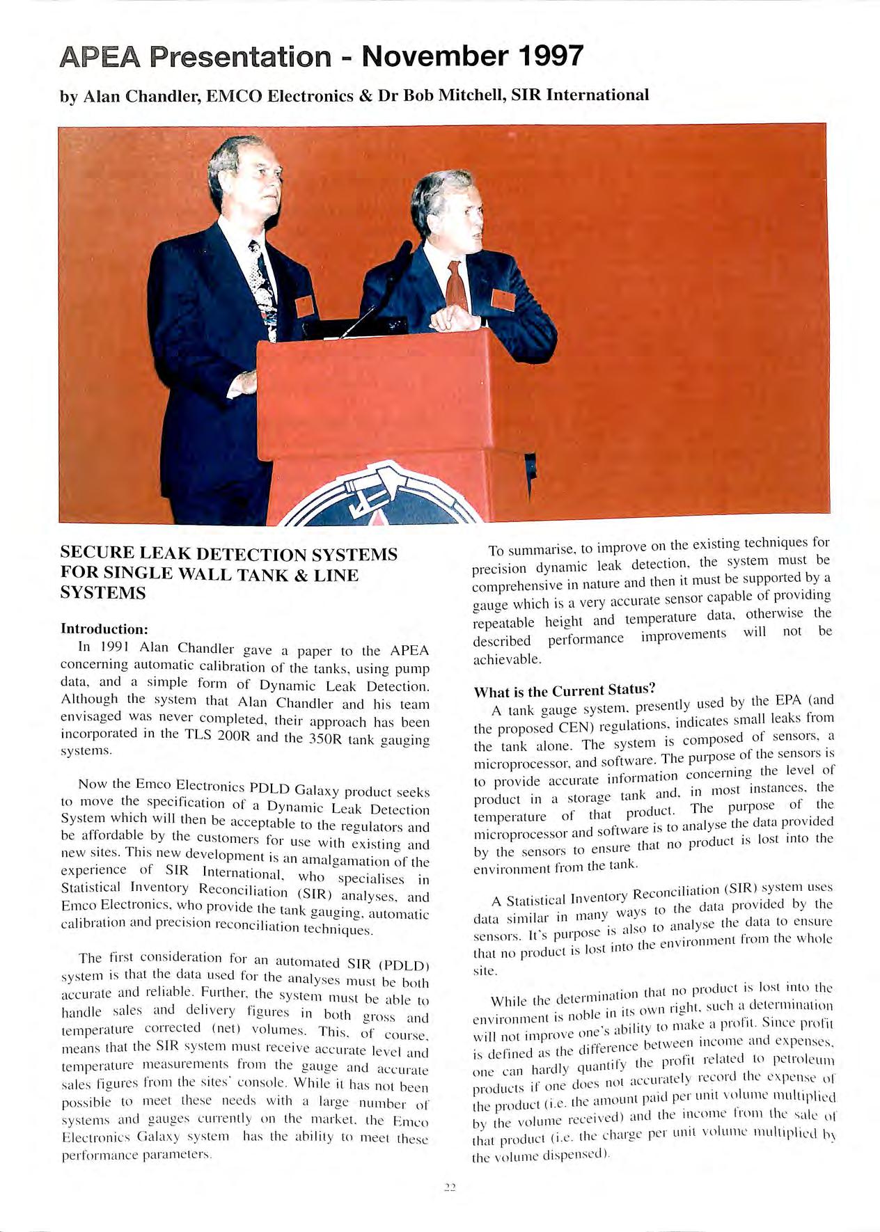 by Alan Chandler, EMCO Electronics & Dr Bob Mitchell, SIR International
SECURE LEAK DETECTION SYSTEMS FOR SINGLE WALL TANK & LINE SYSTEMS
Introduction:
In 199 1 Al a n Ch a ndl e r ga ve a p a p e r to th e A P EA co nc e rnin g a ut o mati c ca librati o n of th e ta nk s, us in g pump d a ta, a nd a s impl e fo rm o f D y na mi c L ea k D e tect io n A lth o ug h the sy s te m th a t A la n Ch a ndl e r a nd hi s tea m e nvi s a ge d w as ne ve r co mpl e te d , th e ir a ppro ac h h as b ee n in co rp ora te d in th e TLS 200R a n d th e 35 0R tan k ga ug in g sys te m s.
N ow th e E m co El ec tro ni cs POLO Ga laxy produ c t see k s to m ove th e spec ifi c ati o n o f a Dyn a mi c L ea k D e tec ti o n S ys te m w hi c h w ill th e n be acce ptabl e to th e re g ulat o rs a nd be a ffo rd a bl e b y th e c us to m e rs fo r u se w ith ex is tin g a nd new s ites. T hi s new d eve lop m e nt is a n a m a lg amati o n of th e ex pe ri e nce of SIR In te rn a ti o na l, w h o s pec ia li ses in St a ti s ti ca l In ve nt o r y Reco nc iliati o n (S IR ) an a lyses, a nd E 111 co E lectro ni cs, w h o p rov ide th e ta n k ga ug in g, a u to m a ti c ca li b rat io n a nd p rec is io n reco nc ili at io n tec hniqu es.
Th e fi rst co ns idera ti on fo r a n a ut omate d S IR ( P OLO) syste m is t ha t the da ta u sed fo r th e a n a lyses mu s t be bo th a cc ur ate a nd re li a bl e. F urth e r, th e system mu s t be ab le to ha ndl e sa les a nd d e liv e ry fi g ures in bot h gross an d te mp era tu re cor rec ted ( net) vo lum es. T hi s. of co ur se. m ea n s tha t th e S IR syste111 m u s t rece ive acc u rate leve l a nd te mp era tur e meas ure m e n ts_ fro m t he ga u ge. a nd acc u rate les J"ia Lires fro 111 th e s ite s co nso le . W hil e 1t h a s n o t bee n Sd · e poss ibl e to me e t these need s w it h a la rge _ nurn b: r o f sys te m s a nd ga uges c u rre ntl y on th e ma r ke t. th e E m co E le ctro n ics Ga la xy sys te m has th e ab il ity to m ee t these pe r fo rlll anc e para m e te rs.
m rov e o n th e e xistin g tec hnique s fo r To summ ari se, t o 1 P 1 system mu st be · I a k det ec ti o n , t 1e prec is io n d y na 1111 c e, d 1 t mu st be s u p po rt e d b y a h na ture an t 1e n i co 111pre e n s1ve 111 p ab\ e of prov icl in o . . ' acc u ra te se nso1 ea , "' oa u ae w hi c h is a \ eiy' cl t a o th e r w ise th e "' "' cl t np e ra trn e a '' re peata ble he ig ht a n e i w· 11 not be improve 111e nt s 1 d escribe d perfo r111 a nc e ac hi eva bl e.
What is the Current Status ? 1 se d b v th e E PA (a nd te lll prese n t y u 1 A ta nk ga u ge sys · d. ates sm a ll leak s fr o m E N ) · a (at1 o n s, 111 ! Cc th e p ro p osed C 1 ec u ' . osed of se nso rs, a TI te m 1s co mp th e ta nk a lo ne. 1 e 5 Y _ s T I ·pose of th e se nso rs is d ft wa re 1e pUI f mi cro p rocesso r. a n so . ' ·. i ce rnin o th e leve l o . 11"o rm a t1 o n co1 o to prov id e accu 1ate 11 cl m os t in s ta nces. the a ta nk a n . 111 • Pro du c t 111 a s to 1a"'e TI _ puriJose ot th e . t rodu ct. 1e tempera ture of t rn t P lyse the da ta pI ov 1decl cl . ft ware IS to a na . I mi cro p rocesso r a n so ·oduc t 1s Jos t 111to t 1e ·e th a t no PI b y th e se nso rs to e ns w , · t 1'1·0111 th e ta n k e n v 1ro nm e n
1., t. o n (S IR ) sys te m uses . Reco nc 1 1a 1 . A S ta ti s ti ca l In ve nt o i y 1 cl 'tta p rov ided b y th e , ' w a ys to t i e ' d tta s imil a r 111 m ct n) . l)' Se th e da ta to e nsu 1e ' ' . a lso to a na se nso rs It's p urpose IS iiro nm e nt fro m the w ho le I t in to t he e ll\ th a t no produ c t is os s ite. ·
1
1 1 0 tJro cl uc t is los t 111t o t 1e · t IOn t ld n W hil e th e cl e te nrnn a "o ht s uc h a cl e te n rn na t m n b le in its ow n I l e , e n v ll'o nm e nt 1s no , 1 , to m ake a p n ll it. S 1n Lt p 1n l1 1 e o ne s a b1 it) . . , w ill no t 1111 p1ov _ b tw ee n m com e .t nu ex pe n ses. h t'ffe re nce e is d e fine d as t e c 1 . , 1 p rofit re lated to pe tro le um II q ua ntil y ti e o ne ca n ha1 c Y il"lte ly re co rd th e expe n se u l do es no t ac e t ' . pro du c ts it o ne 1 p iid IJ e r un1 1 vo lu rne mul t 1p lt ec\ '. e th e ::un o un ' th e prod ull , 1. · I ) 111 c1 th e in com e I m m tht' S<tk o l I , I un e re c e 1vec ' by t i e ' 0 L 1 1 a i ae 11 e r u nit vo lu l11t' 111 ult1p\i l' ll b\ I t ( I ' I 1e c l, c th at proc uc .e. t he vo lum e d isp e ns e d )
Because SIR analyses incorporate both sales and deliveries into its basic paradigm, SIR is in a unique position to determine discrepancies between the amount of product delivered into a storage tank and the amount of product dispensed from it discrepancies, it should be noted, which either cheat the public or which erodes profits. And, as already mentioned, SIR also analyses the data to ensure that no product is lost into the environment.
What is the Objective?
To define the objective, for the new system, it was decided that the user and the regulator would both have to tangible benefits from the implementation of this eqmpment. Therefore the objectives are as follows:
• To offer a long term regulatory environmentally acceptable solution for the existing installed base of un?e:ground tanks and lines. Indefinite relicencing of exzstcng sites without resorting to major capital expenditure. In the future the system will comply with the new UK Petroleum Safety Regulations.
• b_e able to detect a leak rate of 0.8ltrs/hr (0.2 gph) :V1thm 48 hours and progressively develop the system to improve on these figures. Existing regulations are for 0.8 ltrs/hr (0.2 gph) in 28 days.
• To the losses on all sites through the benefits of prec1s10 ·1· · . . n reconc1 iat1on. To improve the cashflow fi·om sites, shortening the payback 011 the expenditure 0 /fltting the system.
• fit the tank gauging into the available sockets on site. hese sockets range from 1 to 4 inches. To replace all the curremly installed gauges, such as Nonnond LS/ &2, CMS 2 &3000. Existing tank gauges 1rith leak detection abilit_\' tend to be only able to fit in 3 or 4 inch sockets.
• To_ eliminate the necessity for modification of the existing tank sockets. The current cost for this service is m excess of £400 per tank. Use only a standard fitting on the ta11k · H · /"/', .1. avmg to moc 11_.- the tank sockets more than douhles the installation costs.
• Te_c_hniqucs are currently being tested to identify meter dnft ln1pro\!ing the possihilitr ol.fitrther increasing site rei·enues and reducing 1•olu111e losses.
• T0 have CEN and EPA certification for the product.
Who i · F' s ,mco Electromcs?
En1co Elect1· >11· · · t· f k < 1cs are a premier manu acturer o · tan gauoes cu.. I 1:- · • 11 ent y supply1110 amH!llH! to many major 011 corn c- c L L Pdnics. I-:mco Electronics i.-, currently sole supplier to Exxon Ne ·tJ A . · ll 1 mcnca and Impcnal Oil o1 Canada.
hnco F!e·t· · I ·1· 1· l T 1·11 (' l' IClllll''>. a SU 1'>1t la!") 0 t 1C U( 11 orporatic I · · WI >n. dnt was formally a suhs1d1ary of the Emco 1eaton. lJ11·1 N ·I , d S 1 1 1ecently operated solely 111 the 01t1 dn · ()LJth Am··· ei ican mark eh.
lhe Tuthill c . · h · · · 1· · 0 1porat1on as 27 suh-,1d1anes opera 1ng 111 X d 1lkrt·111 · · uiuntnc-, amund the world.
Emco Electronics has been installing tank gauges in the retail petroleum industry for over I 0 years and is currently supplying gauges to the markets in the Americas. South East Asia and Europe.
Emco Electronics, an innovator in the market have several firsts to their credit. These include:
First company to use magnetostrictive gauges
First company to develop a fully integrated modular tank monitoring console
First and only company to have all auxiliary sensors supported by one circuit board
First with touch screen technology in the tank gauging field
First to use stainless steel probes as standard
First to offer automatic printed user help instructions
Who is SIR International?
SIR International's SIR program, first certified by Ken Wilcox Associates in 1991, was one of the first SIR programs on the market. This program introduced the concept of the "Minimal Detectable Loss" (MDL) as a means to quantify the quality of SIR data, and was the first program to use the MDL as a means to classify poor data as "Inconclusive". These statistics are now required by the US EPA and virtually all State and Local Regulatory Anent b s 111 the United States.
SIR International is a privately owned corporation With offices Texas and Oklahoma.
Through a network of authorised representatives, SIR International analyses data from sites scattered throughout the United States.
Regulation
the new proposed CEN regulations, and the world wide pressure from the "Gree ,.. · d · · h · d d h ns 1s nvmg t e 111 ustry an t e regulators to furtllei· · improve the leak detection systems for petroleum f11Iino st·ir· . o · ' ions.
Initially the US EPA were implemented with the tanks bemg checked for leaks at the rate of () / d 0 1 ·-an gph using tank gauges or statistical inve 11 to. · 1 . . 1y contro methods. Lmes. which were 111 the main pi·cssLii· . . . e systems. had a separate l me leak detection system adopted. A varict of sensors are also used to support these le"tk d t · y · ' e cct1on systems.
2 l
A brief summary of the current situation follows: -=iEPA-- CEN Tanks 04/o Rltrs/hr -N_umher of _1_111_e_1(l I/() lg_p_h____ : --N···/A--·-_ settl111g time · Pressure lines only System I SIR 0 1/0.'J.gph O.X ltrs/hr in ! 4 days
The major differences in the market place between the USA , where the EPA regulations were developed , and the majority of other te1Titories are:
• The majority of systems outside USA use suction not pressure.
• The tank openings in the USA are 4 inches and the rest of the world had traditionally used 2 inch, (or occasionally 1.5 or even I inch) available openings.
• The number of tanks per s ite can be significantly greater outside the USA .
Tank gauging had become the standard way of leak detecting the single wall tank , but was only really effective when used with an available tank opening of 3 or 4 inches . Therefore, to be effective on the majority of sites, without expensive tank modification s to the man lid , a new technique had to be developed .
A paper was given to the APEA November 1991 which linked the tank gauges into the pump meters and ca1Tied out si mple a rithmetical reconcili atio n techniques This proved a n excellent tool for automatically reconciling the product los ses on s ite and as a sudden loss (large leak) detector. For small leaks the system would take an unacceptably long penod to react.
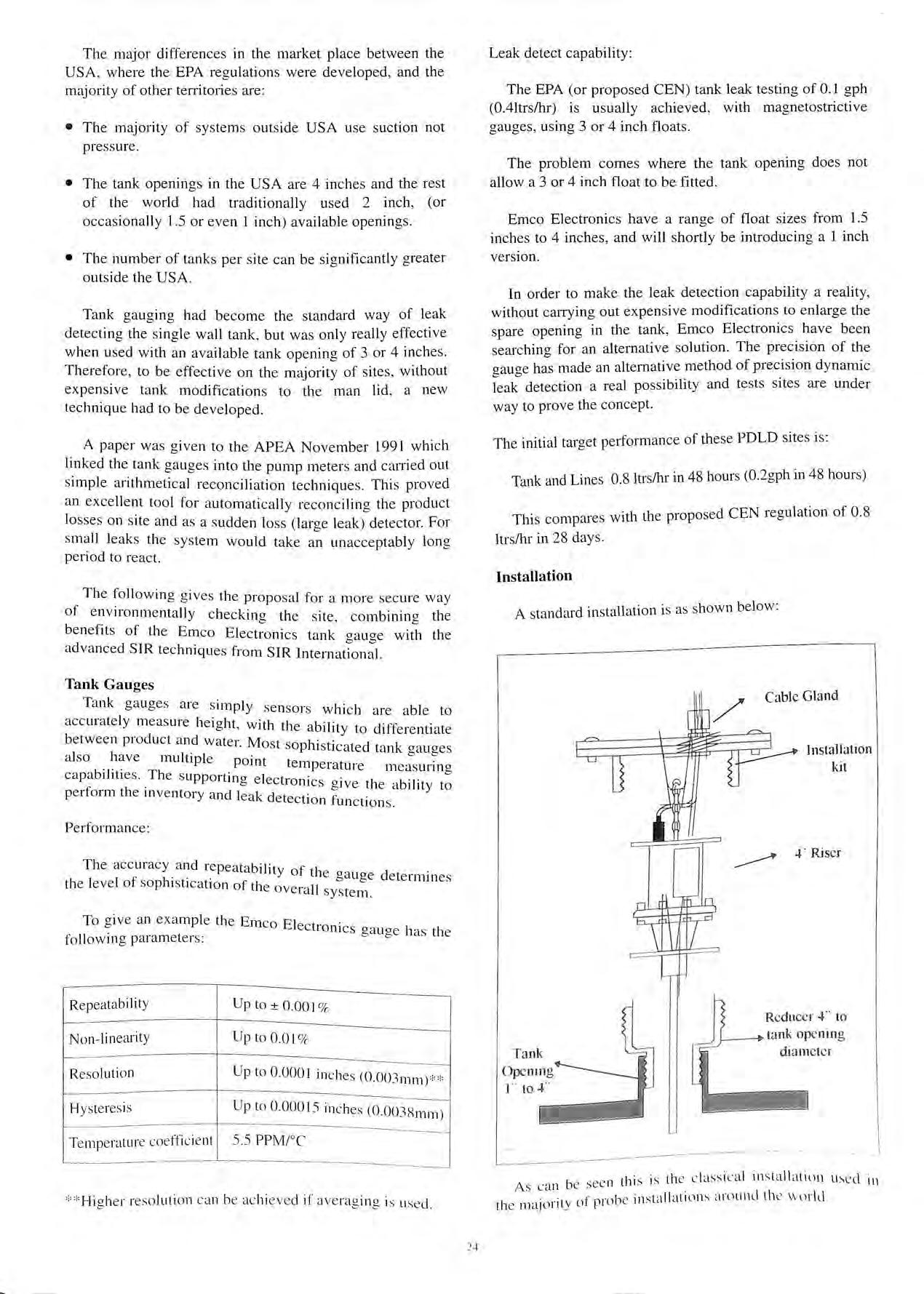
Th e following gives the proposal for a more secure way of environmentally checkino the s ite combinino the b f b b ene its of the Emco Electronics tank oauoe with the advanced SIR techniques from SIR Internati'on:I.
Tank Gauges
Tank gauges are simply se nsors which are able to accura tely measure height with the b·i·t d'ff ' a 1 1 y to 1 erent1ate between product and water Most so 1 1 1 · P 11st1cated tank oauoes a so _1ave multiple point temperature me:suri'n o capabil1t1es The supportino e le t b · b c 10111 cs 0 1ve the ability to perform the mventory and leak d t . b c < e ect1on function s.
Performance :
The acc uracy and repeatability f 1 0 t 1e 0 au 0 e deter ' th e leve l of so ph1 st1cation of th e ov II b b mmes e ia s ystem .
To give an example th e Emco El e ct1omcs oauoe l1 a · tl followmgparameters: b b cS 1e
Repeata bi Ii ty
Non lin earit y
Reso luti o n
Up to± 0.001 %
Up to 0.01 %
Up to 0 0001 in c he s (0 00 3111 111 )**
Hyste res is Up to 0 00015 inches (0 003S ) · . m 111
Te mp e rature coeffici e nt 5.5 PPM /°C
** Hi g he r reso luti on ca n be ac hi ev ed if av e ragin g is used
Leak detect capability:
The EPA (or proposed CEN) tank leak testing of 0 1 gph (0.4ltrs/hr) is usually achieved, with magnetostrictive gauges, using 3 or 4 inch floats.
The problem comes where the tank opening does not allow a 3 or 4 inch float to be fitted.
Emco Electronics have a range of float sizes from 1.5 inches to 4 inches, and will shortly be introducing a 1 inch version.
In order to make the leak detection capability a reality, without carrying out expensive modifications to enlarge the spare opening in the tank , Emco Electronics have been searching for an alternative solution. The precision of the gauge has made an alternative method of precision dynamic leak detection a real possibility and tests sites are under way to prove the concept.
The initial target performance of these PDLD sites is:
Tank and Lines 0 8 ltrs/hr in 48 hours (0.2gph in 48 hours)
This compare s with the proposed CEN regulation of 0 8 ltrs/hr in 28 days.
Installation
A standard in stall at ion is as shown below: Cable Gland Installation kit 4· Ri ser
Red uce r 4 ·· to tank opening diamet er
As ca n be see n thi s is th e cl ass ica l in s tallatinn used 111 th e majority of probe in sta ll at il)Il S around th e w nrld
WhatisPDLD
SIR, as usuall y run today, inv o lves the transmission of manually captured pump and tank data to a service centre , the analyses of those data by a SIR provider, and the di sse mination of the results of the analyses to the site owner/operator. This involves a time lag and makes the analyses and the reliability of the results dependent upon the quality of the data which were submitted by the owner/operator.
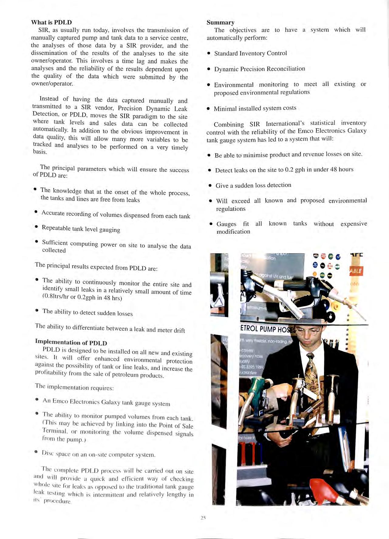
Inste ad of having the data captured manually and tran smi tted to a SIR vendor, Preci sion Dynamic Leak Detection , or PDLD , move s the SIR paradigm to the site where tank levels and sales data can be collected automatically. In addition to the obvious improvement in dat a quality, this will allow many more variables to be tracked and analyses to be performed on a very timely basis.
The principal parameters which will ensure the s ucce ss of PDLD are:
• The knowledge that at the onset of the whole process, the tanks and lines are free from leaks
• Accurate recording of volumes dispensed from each tank
• Repeatable tank level o-au o- in g b b
• Sufficient computing power on site to analyse the data co llected
The principal re sults expected from PDLD are:
• The ability to continuou sly monitor the entire site and id e ntify small leaks in a relatively small amount of time (0.8 Itrs/ hr or 0.2gph in 4 8 hrs)
• Th e ability to detect s udden lo sses
The a bilit y to differe nti ate between a le ak and met er drift
Implementa tion of PDLD
PDLD is de s ig ne d to be in stalled o n a ll new and ex istinos ne s It w ill offer e nh anced e n viro nmental aga 111 st the poss ibilit y of tank or lin e leaks , and increase th e profitabilit y from th e sa le of petro le um produ cts
T he impl e me ntation requires :
• A n E mco Electron ics Ga laxy tank ga uge system
• The a bilit y to monitor pumped vo lum es from eac h ta nk <Th is ma y be ac hi eved by linkin g into th e Point of Te rmin a l, o r monit o rin g the vo lum e di s pe nsed s ig na ls from the pump )
D isc o n a n o n s ite c omputer sys te m.
T he co mpl e te POLO proce ss w ill be ca rri e d o ut o n site a nd w ill pro vid e a qui ck a nd e ff ic ie nt way of c heck in g w ho le s ite for leak s o pp os e d to the traditional la nk ga uge le ak tes tin g whi c h is intermitte nt a nd re lative ly le ngt h y in 1ts' proc e dure .
Summary
The objectives are to have a sys tem which will automatically perform :
• Standard Inventory Control
• Dynamic Precision Reconciliation
• Environmental monitoring to meet all existing or proposed environmental regulations
• Minimal installed sys tem costs
Combining SIR lnternational 's statistical inventory control with the reliability of the Emco Electronics Galaxy tank o-auo-e system has le d to a sys tem that will: b b
• Be able to minimise product and revenue lo sses on site.
• Detect leaks on the site to 0.2 gph in under 48 hours
• Give a sudden lo ss detection
• Will exceed all known and proposed environmental regulations
• Gauges fit all known tanks without expensive modification
The Econ o m ic al Use of Corrosion Control on Se rvice S t atio ns
By Michael K. Baach Executive Vice President Corrpro Companies, Inc., Medina, Ohio, USA
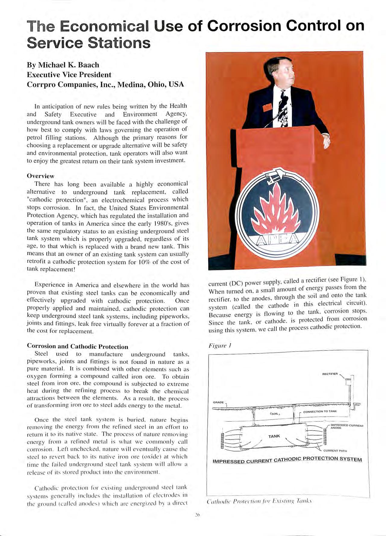
[n anticip a tion of ne w rul es be in g written b y th e Hea lth a nd S a fe ty E xecuti ve a nd En vironment A ge ncy, und e rg round tank own e rs w ill be fa ced w ith the chall e nge o f h ow bes t to comply w ith laws go ve rnin g the operati o n o f pe t ro l fillin g s tation s Alth o u g h the primary re aso ns fo r c hoos in g a re placement o r up g rad e a lte rnative will be safe ty a nd e nvironmental prote cti o n , ta nk o perators will al so w ant to e nj o y th e g reatest return o n th e ir ta nk s ystem inve stm ent.
Overview
Th e re has lon g b ee n ava ilabl e a hi g hl y e c onomi cal a lte rnati ve to underg round ta nk re placement , call e d "ca th o di c protec tion" , an e lec t roc he mi cal proce ss w hi c h s to ps co rro s io n In fa ct , th e U nit e d St a tes En v ironm e nt a l P ro tec ti o n Ag enc y, which h as reg ul a te d th e installati o n a nd o pe ra ti o n o f tanks in Am e ri ca si n ce th e early I 980's, g ives th e sa m e reg ulatory statu s to a n ex is tin g undergroun d stee l ta nk s y s te m w hich is prope rl y up g rad e d , re g ardle ss o f it s age , to th a t which is re pl aced w ith a brand new ta nk. Thi s m ea ns th at a n owner of a n ex is tin g ta nk sys te m c an us uall y re tro fit a ca th o di c protec ti o n sys te m fo r 10% of th e cos t of ta nk re pl ace m e nt !
Ex pe ri e nce in Ameri ca a nd e lsew he re in th e wo rld h as prove n th a t ex is tin g s tee l ta n ks ca n be ec onomi ca ll y a nd e ffec tiv e ly up g raded with ca th od ic protection. On ce p ro pe rly a pplied a nd m a int a in e d , ca thodi c protecti o n ca n kee p un de rg round s teel ta n k s y s te m s , includin g pip e w o rks, j o in ts a n d fittin gs, leak fr ee v ir tua ll y fo reve r a t a fr ac ti o n of th e cos t fo r re plac em e nt.
C orros ion and Cathodic Protection
S tee l used to m a nu fac ture und e rgro und ta nk s, pipewo rks, j o ints a nd fittin gs is n o t fo und in n a ture as a pure m a te ri a l. It is co mbin e d w ith o th e r e le me nt s s uc h as oxyge n for min g a co mp o un d ca ll ed iron ore. To o bt ai n s tee l fro m iro n ore, th e co mp o un d is s ubj ec te d to ex tre m e hea t d urin g th e re finin g p rocess to brea k th e c he mi ca l at t rac ti o ns be t wee n th e e le m e n ts. As a res ult , th e process o f" t ra nsfo rm ing iro n o re to s tee l adds e ne rgy to th e m e ta l.
O nce t he s tee l ta n k sys te m is b uri ed, na ture beg in s removi ng t he e ne rgy fro m t he re fi ned stee l in a n effor t to ret urn ii to its nat ive s ta le T he process of n a ture re m ov in g e ne rgy fr o m a re fin ed m e ta l is w h a t we co mm o nl y ca ll c orro s io n Left un c hecked. nat ure w ill eve nt ua ll y ca use the stee l to reve rt back to it s nat ive iro n o re (ox ide) a t w hi c h t im e the fa il ed und e rgro un d s tee l tan k sys te m w ill a ll ow a re lease of its s tore d prod uc t intn the env iro nm e n t.
C a th od ic protect ion fo r ex is ting u nde rgro un d s tee l ta n k sys te m s ge ne ra ll y in c lud es th e ins ta ll at io n of e lectrodes in t he gro un d (c a ll e d anod es) w hi ch are e ne rg ize d b y a dired
c urre nt (DC ) power s up pl y, call ed a rec tifi er (see Fig ure 1). 1 d Slll all am o unt of e ne rgy passes fro m the W 1e n turn e on , a < < f 1 d es tlii·ou oh th e so il and ont o the ta n k rec tr 1e r, to t 1e a no , "' ( II d tl Ca tll o d e in thi s e lec tn cal c 1rc u1t ). sys te m e a e 1e < • • B · flO Wl ll 0 to the tan k, CO i i OS IOn Sto ps eca use en e rg y 1s "' S 1 k . ca tli o d e is protected fr o m c01Tos1o n 1nce ti e ta n , 01 · 1 t e ca ll th e process ca th o di c p ro tec ti o n us m g t 11 s sys e m , w
re I
S T..!;M_
Figu
IM PR ESSED CURR ENT C ATHODIC P ROTE C T ION S Y
Cuthodic Prm ectio11 .fi11· l:'.ris1i11x Tu11k.I
It is important to note that properly applied and maintained, cathodic protection will keep a tight tank system, both new and existing, leak free forever. Therefore, replacement should never be necessary.
To be effective, cathodic protection requires that current flows from the cathodic protection anode, through the electrolyte, onto the cathode surface. Through the addition of energy the cathode, or protected structure, maintains the energy level of the refined metal. A familiar application of cathodic protection is household hot water heaters. Small magnesium anode rods are installed inside the tank to provide cathodic protection to the submerged metallic components.
Because cathodic protection current must flow onto the metal surface, cathodic protection can only be applied when the structure is buried, submerged or embedded in an electrolyte such as water, soil or concrete. Unfortunately, cathodic protection is not applicable for controlling atmospheric corrosion. It therefore cannot be used in the form herein described to protect automobiles from corroding. For atmospheric corrosion, a process called galvanizing, which is essentially the deposition of zinc on a steel surface, is used as a form of cathodic protection. The zinc is the anode and the steel is the cathode. In this case, the cathodic protection anode is directly applied to the surface of the cathode.
Most importantly, the ongoing operating cost of a cathodic protection system is very reasonable. The cost for electricity for a system at a typical service station is usually less than the cost of operating a 100-watt light bulb. This means the annual power cost is less than £60 in most areas of the country. Further, with the implementation of relatively simple remote monitoring devices, ongoing cathodic protection system inspection costs become insignificant.
Coating Alone: Ineffective for Corrosion Control
Coatings are often used for corrosion control of buried structures. The purpose of a coating is to insulate the anode and cathodes of the corrosion cell from the environment. In theory, by insulating the metallic surface from the electrolyte (soil). coatings prevent the corrosion reaction from occurring. However. in practice by using coatings alone as a means of corrosion control on buried steel, the structure will generally fail sooner than if it had been left bare. This is because no matter how well the coating is applied. no coating is perfect. Voids or holidays in the coating will invariably exist. These may be large enough to he seen or may he tiny microscopic pinholes that cannot even he detected with a flaw detector.
Attempts have been made to achieve perfect coatings. These efforts have provcn to he both unsuccessful and prohibitively cxpensive. Coatings will also deteriorate with time and suffer from both imperfection and aging.
When a bare metal is buried, the release of energy usually occurs over the majority of the metal surface. For a coated structure, because no coating is perfect the energy release, or corrosion, is concentrated at voids or damaged areas of the coating, thus acceleratmg corrosion penetration of the steel structure. As a by applying a coating as the only form of protection, the steel structures will generally fail sooner than if left bare.
A better, more effective method of corrosion control_ is to provide new structures with a combination protective coating/cathodic protection system.
For a coated steel structure, the cathodic protection system needs only to provide protective current to the of the structure where flaws, voids or coating _damage
Therefore, a combination coating/cathodic corrosion control system provides the most effective, economical method of corrosion protection for new_ steel tanks, pipeworks and fittings while assuring the highest degree of environmental protection.
Tank Modification by Internal Lining
Numerous industry studies have determined that the primary corrosion mechanism which causes underground tank failure is from the external soil side tank
When an internal lining is applied without external cathodic protection, the remaining tank shell will to deteriorate due to external corrosion until such time as the weight of the stored product exceeds the mechanical strength of the lining, when a release can occur.
There are a number of industry guidelines and which outline proper procedures for applying mt_ernal lining to repair underground tanks. However, has proven that internal lining alone will not provide the desired corrosion protection for an underground tank. In fact, the preamble to the United States Environmental Protection Agency's Underground Storage Tank rules
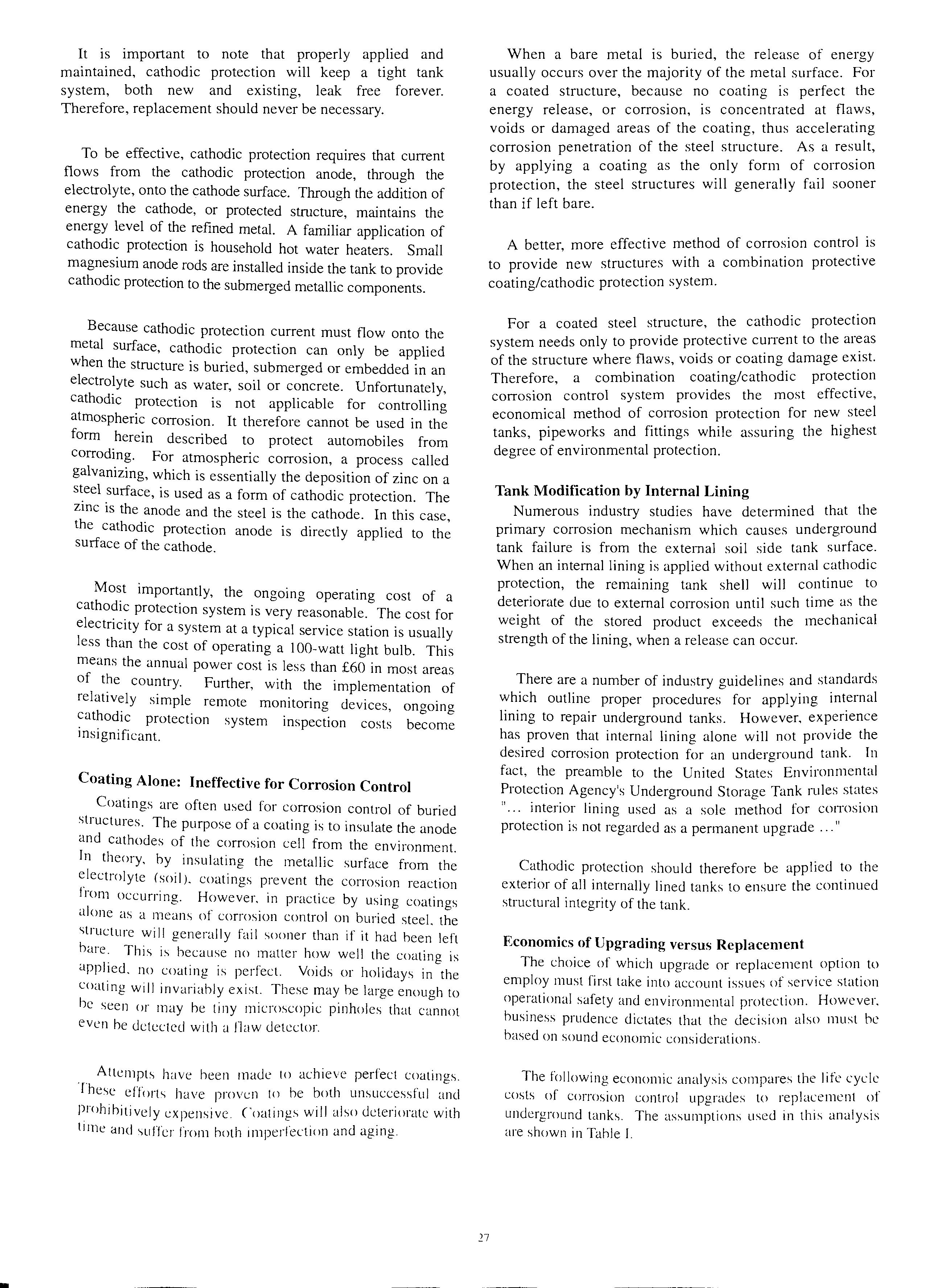
11 ••• interior lining used as a sole method for COJTOslOn d II protection is not regarded as a permanent upgra e ···
Cathodic protection should therefore be applied t? the exterior of all internally lined tanks to ensure the contmued structural integrity of the tank.
Economics of Upgrading versus Replacement
The choice of which upgrade or replacement option to employ must first take into account issues of service station operational safety and environmental protection. However. business prudence dictates that the decision also must he based on sound economic considerations.
The following economic analysis compares the life cycle_ costs of corrosion control upgrades to replacement ot underground tanks. The assumptions used in this analysis are shown in Table I.
-
• 3@ 40,000 litre Tanks per Site
• 25 Year Note
• 7% Cost of Money
• 4% Inflation Rate
• £5,000 CP Upgrade
• £11,000 Internal Lining
• CP Maintenance: £60/yr Power £60/yr to Inspect
• 32% Tax Rate
• Removal/ Replacement Costs:
• £40,000 Single Skin System
• £75,000 Double Skin System
Table I Assumptions
By performing pre sen t worth calc ulations , it can be shown that the a nnuali ze d present value (PY) cos t for replacem ent of tank s and pipeworks at a typical se rvice station with double sk in structure s is approximately £5 ,800 (see Table II) , plus the cos t of any required contaminated so il clean up Cathodic protection can be retrofitted to the existing tanks and pipeworks at the same facility at an annualized present value cost of approximately £560. Therefore , cathodic protection can be applied to struct urally sound tank s and pipeworks at a sav in gs of more than 90 % of the cost of replacement. (See Appendix A fo r act ual calculations.)
To express th ese up g rad e and rep laceme nt figures in cos t per litre of product so ld , an a s s umpti o n was mad e that the typical serv ice sta tion dispenses 167 ,OOO litre s of petrol pe r month. The results of this average cos t per litre are s how n in Table II.
devices can norm ally be accom plished in one day without req uiring any business sh ut do w n Thi s means no loss of reve nues or customer loyalty.
Human beings are truly creatures of hab it. This is demonstrated by a sto ry recently told to us by a lo cal convenience store operator. During a remodeling program , each of his facilities was c lo sed for 48 hours. Naturally, hi s reauiar customers found alternative places to do business this period. Unfortunately, the customers did not immediately return after the s tore reopened . In fact, it took this operation an average of 60 da ys to recover to the previous bu siness vo lume after being closed for only two days. Therefore , by up grad in g a si te with protection rather than replacing the ta nks ,_ a n_ owner gams the added economic benefit of cont111u111g busmess operations , uninterrupted , while th e tank system modifications are accomp li shed.
Summary .
Owners and operato rs ca n up gra de th eir und ergro und steel tank systems at a fraction of the cost of replacement. B , properl y installing and maintamm g a cat hod ic ) · tern tinderaround stee l tanks can be kept leak protection sys , o S tl APEA/IP Draft Code of Practice fo r the free . mc e 1e f t. 1 stat i ·ons allo w for th e mod1 f1cat1on of operation o pe 1o ' ' . . . d . . d tee! tanks with cathodic protection , ope1 at01 s un e1g1oun s 1 b f't from this econo mical alternative to tank can a reat y e ne 1 0 1 1 ss urin a a safe, environmentally replacement w 11 e a o. protective petrol storage operat ion.
b Mr Michael Baach, Executive This paper was wntten ' · ? • f C . Coll1J?mues, In c the wo1ld s Vice President o oi ipw · · · 1 · 011 control and 1110111tor1ng 1 I nrov1der 0 . CO i !OS I ear, 111g !_, · · Mr Baach can he / o. For more 1nformat1on 1ech110 0"' 1es. · / 1090 Enterpnse I C IT/'JrO Compm11es, nc., co11tacteG at o 330 72 3 _5082 (phon e), 330Drive Med11w , Ohio 44256 ' Ji·o com (websit e). 723-0244 (fax), or WWW.CO i i/
Tank
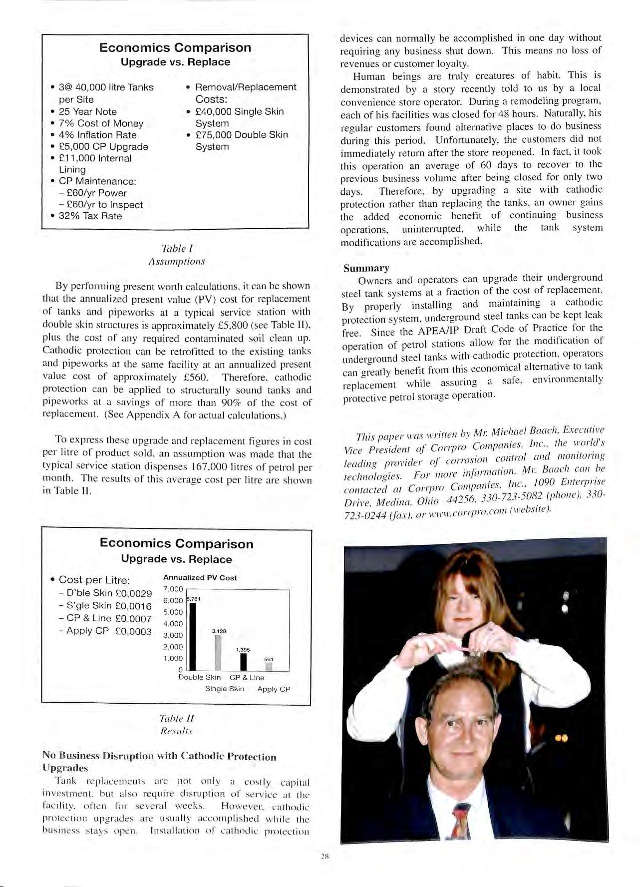
Comparison
vs.
Economics
Upgrade
Replace
Economics Comparison Upgrade vs. Replace • Cost per Litre: D'ble Skin £0,0029 S 'gle Skin £0,0016 CP & Line £0,0007 Apply CP £0,0003 Annualized PV Cost 7, 000 6 ,000 7 8 1 5, 000 4,000 3,000 3,128 2,000 1,395 1,000 Double Ski n CP & Line Tahl e II Results Single Skin Apply GP No Business Disruption with C athodic Protection Upgrades
me nt
di
28
re p lac e
s are no t on ly a co s tly c apital in ves tm e nt. bu t a ls o re qu ire
s ruption of ser vic e at th e fa c ilit y. ofte n for seve ral wee ks Ho we ve r. c athodic prote ction up g rad es a re us uall y accomp li s he d w hi le th e bu s in ess s ta ys ope n In s ta ll at ion of ca th odic prote ction
Year 1 2 3 4 5 6 7 8 9 10 11 12 13 14 15 16 17 18 19 20 21 22 23 24 25 Year
Appendix A Life Cycle Cost Analysis Calculations
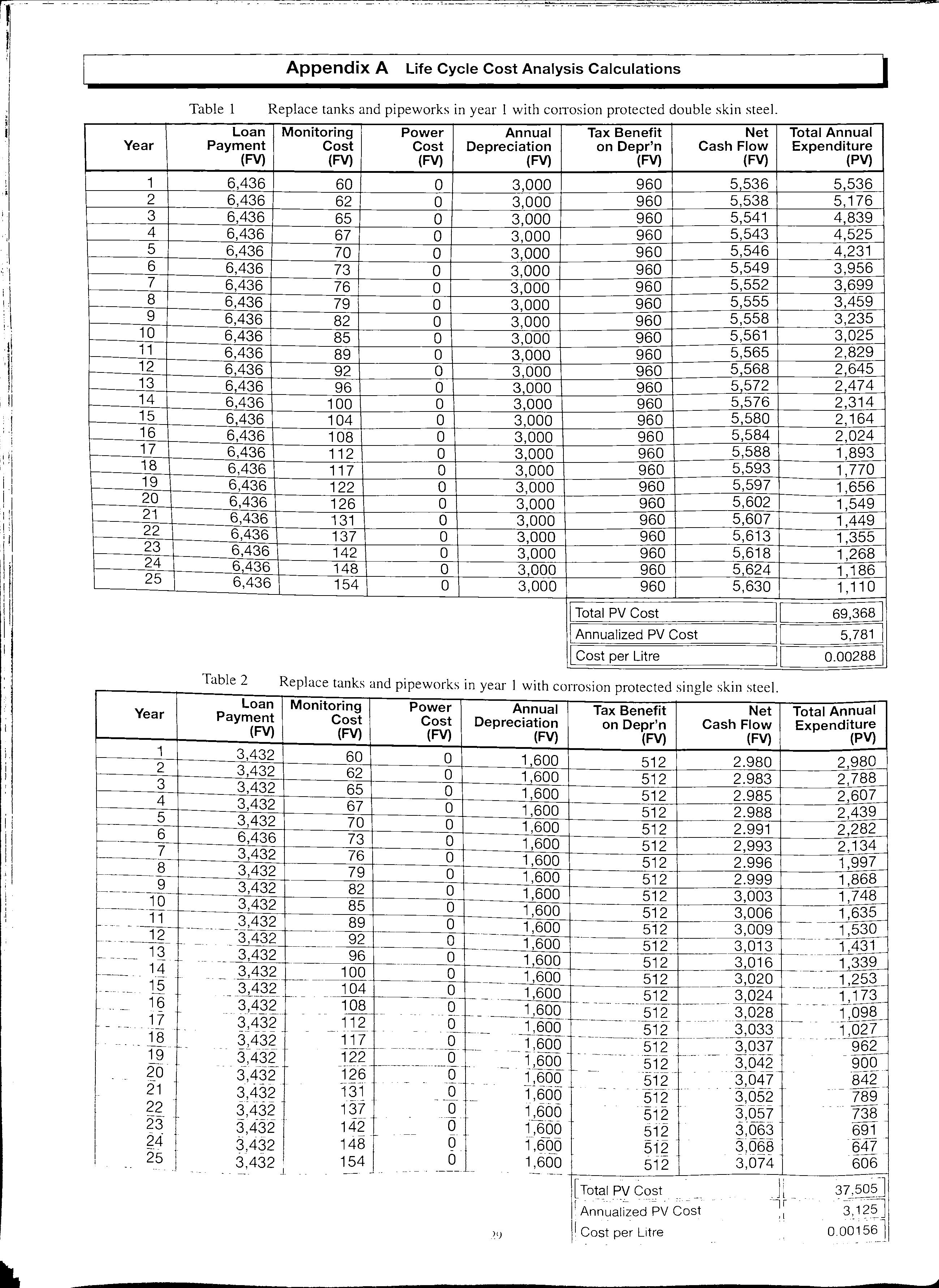
Table 1 Replace tanks and pipeworks in year I with corrosion protected double skin steel. Loan Payment (FV) 6,436 6,436 6,436 6,436 6,436 6,436 6,436 6,436 6,436 6,436 6,436 6,436 6436 6,436 6,436 6,436 6,436 6,436 6,436 6,436 6,436 6,436 6,436 6 436 6,436 Table 2 Loan Payment (FV)
Monitoring Power Annual Tax Benefit Net Total Annual Cost Cost Depreciation on Depr'n Cash Flow Expenditure (FV) (FV) (FV) (FV) (FV) (PV} 60 0 3,000 960 5 536 5,536 62 0 3,000 960 5,538 5,176 65 0 3,000 960 5,541 4,839 67 0 3,000 960 5,543 4,525 70 0 3,000 960 5,546 4,231 73 0 3,000 960 5,549 3,956 76 0 3,000 960 5,552 3,699 79 0 3,000 960 5,555 3,459 82 0 3,000 960 5,558 3,235 85 0 3,000 960 5,561 3,025 89 0 3,000 960 5,565 2,829 92 0 3 OOO 960 5 568 2 645 96 0 3 OOO 960 5 572 2 474 100 0 3,000 960 5,576 2,314 104 0 3,000 960 5,580 2,164 108 0 3,000 960 5,584 2,024 112 0 3,000 960 5,588 1,893 117 0 3,000 960 5,593 1,770 122 0 3,000 960 5,597 1,656 126 0 3,000 960 5,602 1,549 131 0 3,000 960 5,607 1,449 137 0 3,000 960 5,613 1,355 142 0 3,000 960 5,618 1,268 148 0 3 OOO 960 5 624 1 186 154 0 3,000 960 5,630 1,110
ITotal PV Cost II 69,368 I IAnnualized PV Cost II s,781 I ICost per Litre II 0.00288] Replace tanks and pipeworks in year I with corrosion protected single skin steel Monitoring Cost (FV) Power Cost (FV) Annual Depreciation (FV) Tax Benefit Net Total Annual on Depr'n
'1 ',, ' ' 't
'!
1 3,432 60 0
2 3,432 62 0
3 3,432 65 0
4 3,432 67 0
5 3,432 70 0
6 6,436 73 0
7 3,432 76 0
8 3,432
0
10 3,432 85 0
L. 11 3,432 89 0
f-----.-_lg_ 3,432 92 0
3,432 96 0
14 3,432 100 0
TE( 3,432 104 o
___
__ 108 1-- 1,600 512 __
.___
___ ____ 1J1 __ , ___ Q_I---_ 1,600 512
·----------1----- 117 __Q__f--__ 1,600 512
962 ___ rn __ _ __ 3,43g_ ____ 122 _____ =-1'MO- -------512 3,042- --95Cl ?_O _ 3,432 ____ ___ 1,600 --512- -3,047 -1342_ 3,432- 131 ______ __Q_ _ -l6o5 5-12 -3,052- 789 ?_?_ :{432 - 1_37 ____ ___Q __ l66o ·512- - -- -
L. --73823 3 432 142 0 1 600- --512
?4 3-,'432 148 '-· - ---- - 0 -- 1'.6115 3-068 -647512 -' 2!)_ 512 3,07 4 606 [Total-Pv Cost ·- Jl _ 37-'5()5] --1: -=c Litre :, o.§o256J .'.'!
Cash Flow Expenditure (FV) (FV) (PV}
1 600 512 2.980 2,980
1,600 512 2.983 2,788
1,600 512 2.985 2,607
1,600 512 2.988 2,439
1,600 512 2.991 2,282
1,600 512 2,993 2, 134
1,600 512 2.996 1,997
79
1,600 512 2.999 1,868
1,600 512 3,006 1,635
1,600 512 3,009 1,530
1 600 512 3,013 1,431
1,600 512 3,016 1,339
1,600 512 3,020 1,253
1,600 512 3,024
1, 173
3,028
1,098
3,033 1,027
3,037
3,057
3;063 691
·l___ \ \ WARNING. VEEDER ..ROOT It Z : V(h.UME :1\)2·' L\'\ :."1\:.S :ttj ±8 OTHER MANUFACTURERS' GAUGES COULD SERIOUSLY DAMAGE YOUR WEALTH. Official Warning from the Market Leaders in Tank Gauging.

Ill Drill S Entries For: e Gauging Systems e Vapour Recovery e Overfill Prevention e Submersible Pumps e Additional Lines The only system in commercial use comprehensively tested using thermal imaging technology by the health & safety laboratory A c knowledged as a safe working practice Ig ni t ion S afe D rilling A nd T hreading o ol Drill Safe National ervice Tel: 44/0990 133111 Fax : 44/0990 133110

Tan k Gaugin g and Leak Detection LIQUID FILLED AND DRY AIR PRESSURE LEAK DETECTION SYSTEMS FOR STEEL OR GAP DOUBLE SKIN TANKS. I \ I I ' 40 60 / '20 80' \.-..;, I cfG site = LEAK DETECTION SYSTEMS FOR DOUBLE CONTAINMENT PIPES, ACCESS CHAMBERS AND PUMP ISLAND SUMPS. " PROLEVEL" TANK GAUGING SYSTEM FOR UP TO 16 TANKS. PC AND MODEM COMPATIBLE FOR LOCAL AND REMOTE MONITORING. " TANKGUARD'' LOW COST ELECTRONIC TANK GAUGING SYSTEM "TANKMATE 160" SELF-POWERED TANK GAUGE FOR DIESEL AND GAS OIL. INTERCEPTOR AND OIL SEPARATOR LEVEL ALARM SYSTEMS BS EN ISO 9001 QUALITY ASSURANCE ALL SYSTEMS MEET RELEVANT SAFETY STANDARDS. EEx ia /IC FOR ZONE 0 AND EEx ib /IC FOR ZONES 1 AND 2 ················································ Why not talk to the specia/ists: EUROGAUGE COMPANY LIMITED IMBERHORNE LANE , EAST GRINSTEAD , WEST SUSSEX RH19 1RF Tel: 01342 323641 Fax: 01342 315513 Quality services for today's forecourt HIGH QUALITYRE- IMA GINGOF PUMPS, CA NOPIES, SHOPS POLE SIGN ERECTION & MODIFICATION PLA NNED IMAGE MAINTENANCE PROGRAMMES PUMPS &EQUIPMENT - HAULAGE, STORAGE &DISTRIBUTION Valley Road, Cinderford, Gloucester GL 14 2NY Telephone: 0594 826364 Fax: 0594 822807

I You deserve wysettle for less ... THE LEADER IN PETROLEUM TANK MANUFACTURE Including: • SUCTION PIPES • FILL PIPES • OVERFLOW PREVENTION • CHAMBERS • GROUND COVERS, and much more ... l "

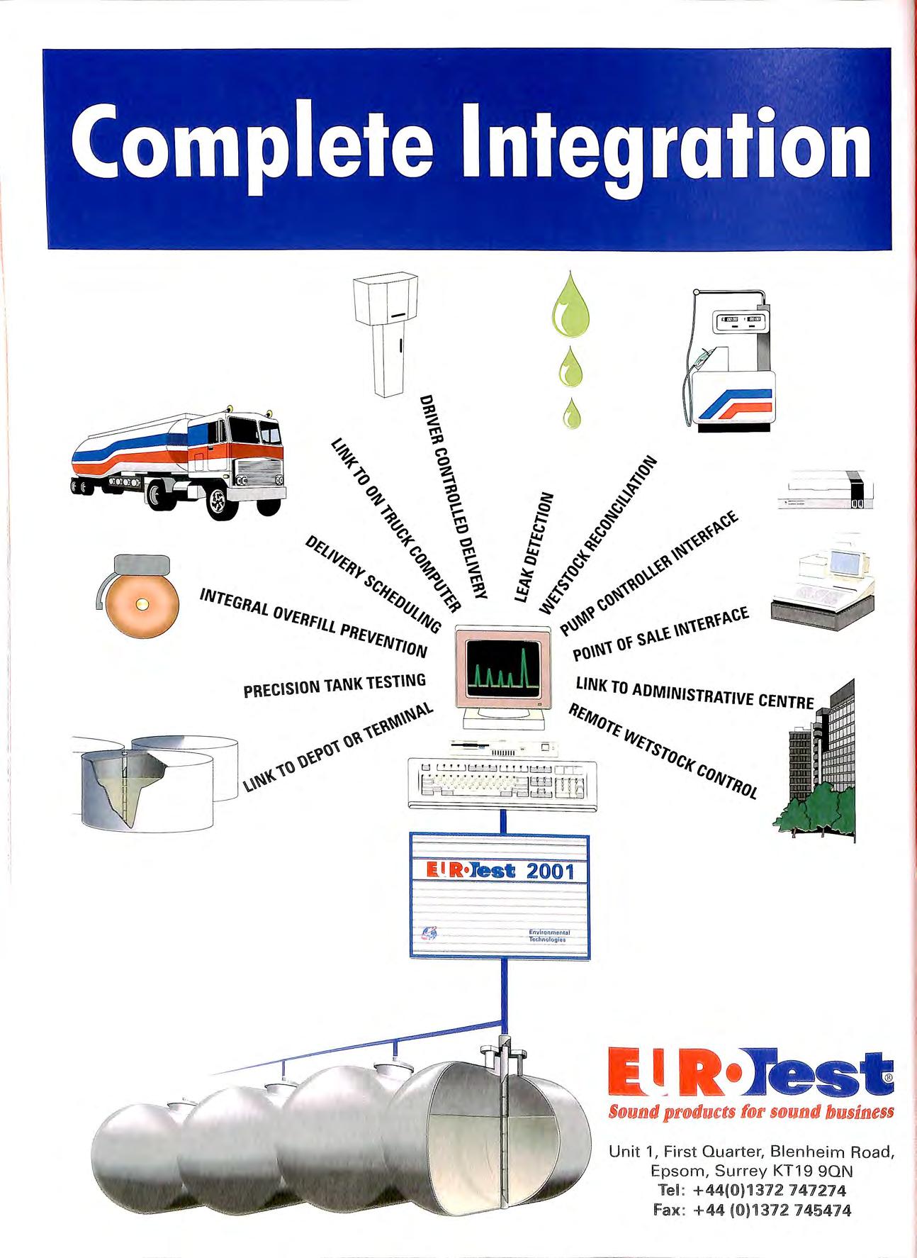
Complete Integration R•Jest 2001 Env ron m1in111 t -----., =.-,.. 1-- ' I Unit 1, First Quarter, Blenheim Road , Epsom, Surre y KT19 90N Tel : +44(0)1372 747274 fax : +44 (0 )1372 745474

pOLV-Tt::CH '" Advanced Flexible Underground Piping System 0 Ease of Installation 0 Cost Effectiveness • Pressure or suction applieation • All fuels UL/ULC listed • DiMct bu•ial or second a ry containment

I I I SPECIALIST ELECTRICAL ENGINEERS &CONTRACTORS TO THE PETROLEUM INDUSTRY • Close-circuit TV • Fire Alarms & Emergency Lighting • Planned Maintenance • Inspection & Testing • Forecourt Earthing Systems The Electrical Contractors' Associ.atio11 REGISTERED MEJ\ffiER MEMBER OF A.P.E.A Nationa Inspection Council for Electrical Installation Contracting E e RIC. L S RV C P 0 HEAD OFFICE: PROJECT HOUSE ·THE DRIVE · WORTHING · WEST SUSSEX · BN11 5LL TEL: 01903 700321 BY TOTAL CONTAINMENT Low cost, flexible solutions for all fuel pipework P!URF l EET FORECO URT • Most flexible pipework system • No underground joints • Suitable for alternative fuels e High flow rates ° Competitive prices = TOTAL CONTA I NME N T 520 London Road, W est Thurrock, Grays, Essex RM20 3BE Tel: 01708 863931 Ext 219 Fax: 01708 864140 Sole UI< PURFLEET FORECOURT SERVICES LTD Distributor

M H PARTNERSHIP SURVEYORS, PROJECT MANAGERS, ARCHITECTS 30 YEARS EXPERIENCE IN THE DESIGN , PLANNING, CONSTRUCTION AND COST CONTROL OF SERVICE STATIONS, SHOWROOMS AND WORKSHOPS THROUGHOUT THE COUNTRY FROM THE INSTALLATION OF A SINGLE TANK TO A COMPREHENSIVE DEVELOPMENT 3 Park Court, Pyrford Road, West Byfleet, Surrey KT 14 6SD Tel: 01932 352727 Fax: 01932 351545 email : mbhptshp@compuserve.com FORMERLY McCARTHY BAINBRIDGE PARTNERSHIP Cp INSTALLATIONS LTD. (Established 1968) • Specialists in Petroleum Pipework Installations • New and existing Tanks and Lines tested • Modifications lo existing Installations • And all work associated with Forecourt Pipework • Approved for UPP, Durapipe and Enviroflex Pipework Installations • Approved lor Ameron and Smiths Fibreglass 1ns1allalions Unit 2, 275 Prince Avenue j Westcliffe on Sea, Essex SSO OJP. Tel: 01702 392110 (24hrs ans) Fax: 01702 392126 0 CREATE LESS VAPOUR • 0 u u • LOSE LESS MONEY! • • I Lincoln Partners Limited 1 Crossways House Enderby Road Slaby Leicester England LES 4DD Tel: 0116 277 2700 Fax: 0116 277 2900 THE FASTEST WAY TO :• Put 2 3 & 4 .. threaded entries into tank lids • Remove drop tubes 11 II I II & I O PD's (including 4 steel tubes) nsta supp y • Remove any existing sockets Ill Safe accepted by HSE appropriate safety authont1es • Quick Ill Cost effective ff M A K ES GOOD SENSE TO USE aoRTIEC Ltd Hudson Hill H edingha111 Road ,Wethe1·sfield. Brainffee, Essex CM7 4EH Tel (0 1371) 850921 Fax (0137 1) 8507 19
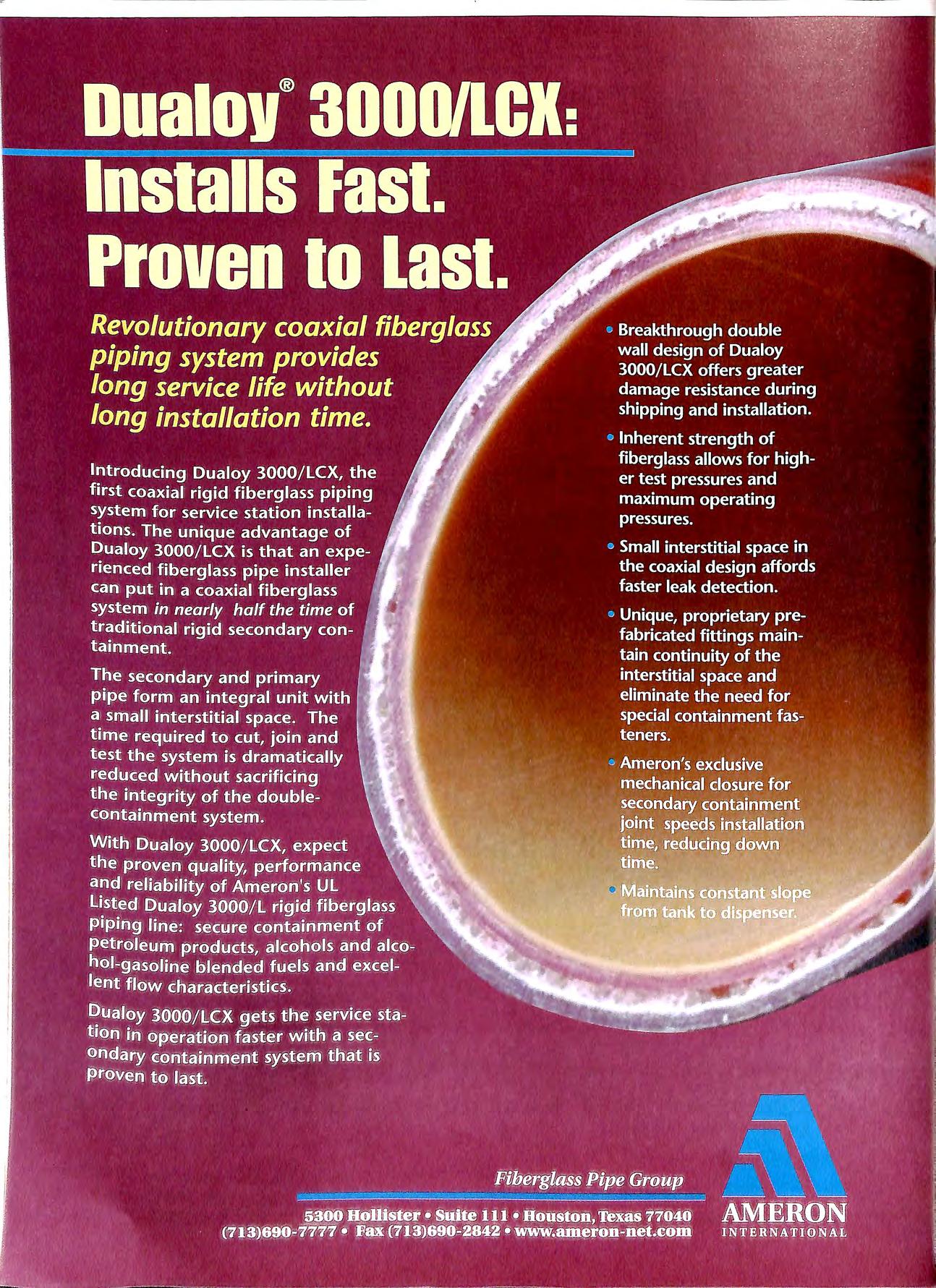
With more than 20,000 installations throughout USA and Canada CONVAULT is the premium above ground vaulted storage tank system available today.
Now CONVAULT'S patented system is in
United Kingdom and Ireland. 1l1is cost effe_ctive above ground fuel storage system is ava1lable for use by Ftre Authorities, Airports, Schools, Hospitals, Govt Depts, Golf Courses, Marinas , Private Business etc. · 1 lt t" e for storina petroleum based products and A pract:Jca a e1 na iv "' NVAULT'S other flammable or hazardous :ubstances. CO UL 2085 Listed design is engmeere,.d___ for Safety, addressing strict
environmental and fire
safety requirements. Capacity from 2000 16000 Litres.
Environmental Engineering & Applied Science Extensive experience in undertaking specialist contaminated land remediation in the UK and Europe provides clients with tried and tested methods, applied by specialist staff, for dealing with polluted land and groundwater. • Site assessment on petroleum retail sites and industrial premises • Fully costed remedial design proposals • Execution of remedial works with minimum disruption • Confidential prompt and professional service SPECIALISTS IN CONTAMINATED LAND CONTRACTING Telluric Ltd, Meandros House, 54A Bute Street, Cardiff Bay, CF1 6AF. Tel: 01222 303010 Fax: 01222 303011 Sofitam Pump Services Ltd • Forecourt & Commercial Pump Maintenance • Sole UK Approved Distributor of Beck Parts • Fuelling Equipment Stockists • Refurbished Equipment • New Forecourt Equipment Independent Pump Services Ltd • Pipework Installation • Tank Testing • Project Management SOFITAM Call us on (01273) 454831 Adur Baatyard, Old Shareham Raad, Shareham-by-Sea, West Susse>e BN43 5TA. Tel: (01273) 454831 Fax: (01273) 464863
1r::lfau• •I
......,.,. __..., ,
I" I
SPECIALIST IN ALL TYPES OF PETROLEUM INSTALLATION CONTRACTING & lVlAINTENAN CE· INDUSTRIAL I COMMERCIAL I AIR CONDITIONING WITH OVER 20 YEARS EXPERIENCE 24 HK 7 DAY SERVICE ALL YEAR CALL-OUT FACILITY. • Breton Precast Ltd 122-126 Duncrue Street Belfast BT3 9AR Telephone: 01232 351711 Fax: 01232 754053
th:
I I I
I htpp://www.breton.co.uk
TANK UNING
Installation of retro-fit Double or Single Skin lining systems using the well proven "ADISA" systems used over a 20 year period by major oil companies throughout Europe. f
One Albion Street Failsworth Manchester M35 DEG TEL: 0161 684 8534 FAX: 0161 688 4101
TANK
TANK SERVICE UNITS
All equipment has been designed and constructed to be granted UK and TUV European Petroleum Regulation approval for product uplift and transfer in conjunction with inflammable liquids belonging to all dangerous categories.
All works undertaken in strict compliance with HSE and Petroleum Regulations including "OCTEL" Leaded Gasol in e Tank Cleaning standard and TuV approval.
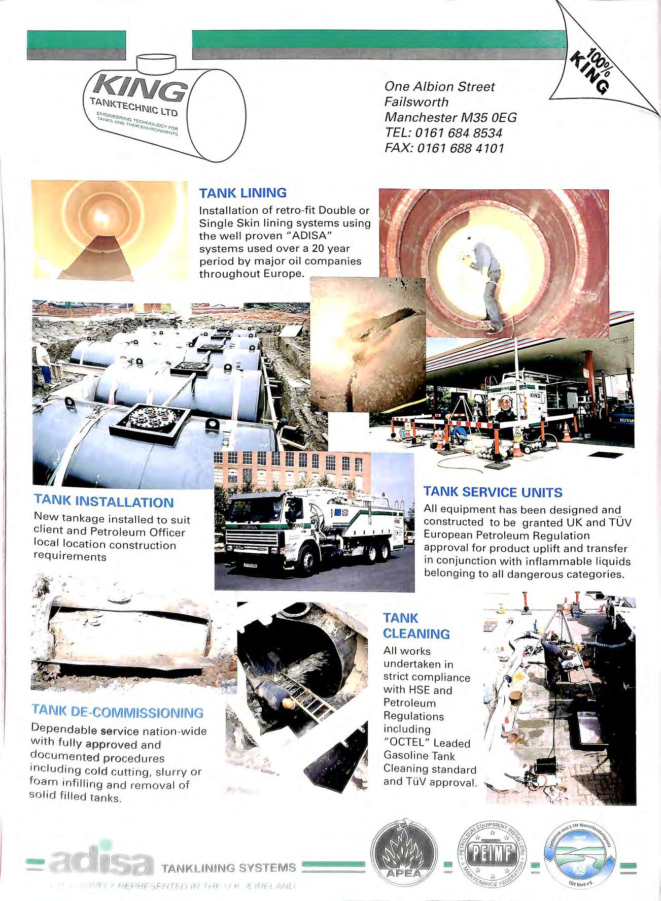
New tankage installed to suit client and Petroleum Officer local locat i on construction requirements ' ',,, / TANK Dep e ndable service nation wi d e w ith fu ll y approved and documented p rocedu r es inc l ud in g cold cutt i ng, s l u rry or foam in f i lli ng and remo v a l o f sol id f ill ed t anks ' ' ... SVSTIEM S ==== /'IF I / f-1F-PRFSEf\JTEU IN II-IF 11 /<" AIJ[J
TANK
A dd. .
our extensive list of products, f e fac1l1ty to manufacture a wide range 0 engraved signs for many Industries. With controlled machines, including AD fac1lit1es you can now order your signs with the rest of your material. Fabrication Mild Steel Fabrications have complemented our supply to the Forecourt Industry for many years, made to either our own design, or to customers specifications. • Steel Tube and Section Fabrications • Pump Stands •Vent & Offset Fill Frames • Pump Barriers • Manifolds • Security Gates and Grilles
Equipment CHAMBERS, SUMPS & DRAINAGE Polyethylene: Tank Chambers and Dispenser Sumps. G.R.P.: Tank Chambers with Corbel Tops, Dispenser Sumps with Pump Stands. Interceptors, Separators and Silt Traps. ACCESS COVERS G.R.P. Lightweight or Heavy Duty Steel Covers and Frames. The One Stop Shop! D. Berry & Co (Pipe Fitting Supplies) Ltd., Unit 130, Middlemore Industrial Estate, Kentish Road., B'ham 821 OAY. Tel: 0121 558 4411 Fax: 0121 555 5546.
Signs & Labels
Forecourt

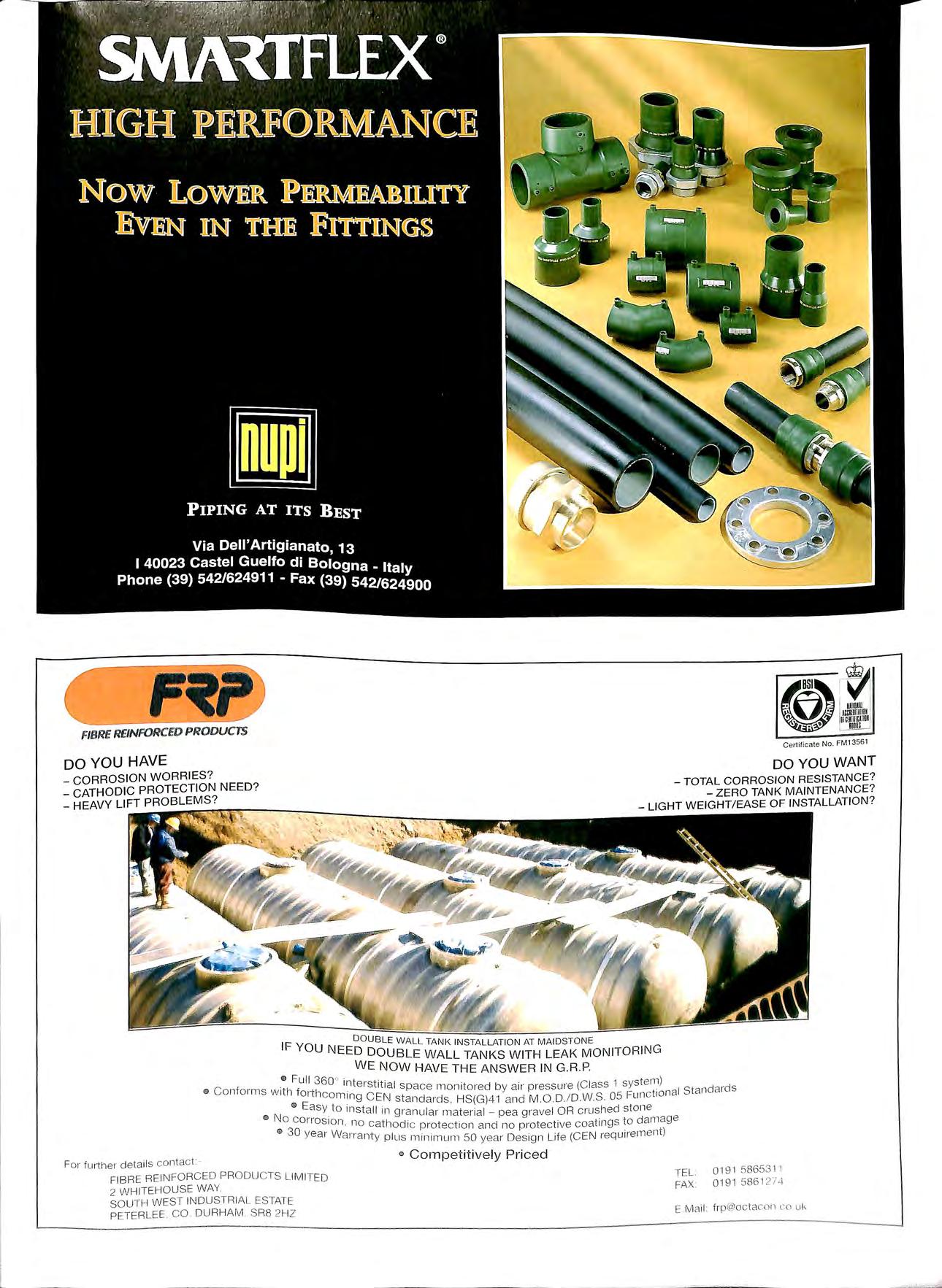
FIBRE REINFORCED PRODUCTS DO YOU HAVE CORROSION WORRIES? Certificate N o. FM13561 DO YOU WANT TOTAL CORROSION RESISTANCE? CATHODIC PROTECTION NEED? _ HEAVY LIFT PROBLEMS? ZERO TANK MAINTENANCE? LIGHT WEIGHT/ EASE OF INSTALLATION? IF YOU WALL TANK INSTALLATION AT MAIDSTONE DOUBLE WALL TANKS WITH LEAK MONITORING WE NOW HAVE THE ANSWER IN G.R.P. ., Fu ll 3600 interstr I ) o Conforms with forth 1ra space monitored b y arr pressure (Class 1 system d d 0 Eas CEN stanclarcls, HS(G)41 and M .0.D ./D ws 05 Functional Stan ar s 0 No . Y install 111 granular mat erial pea gravel OR crushed sto ne conos ron no tl · · d age 0 30 e r ·.. ea i odrc protect1011 and no protect ive coatings to am Y a War1anty plu s m1n1mum 50 year- Desig n Life (CEN requ irement) For further details contact: FIB RE REINFORCED PRODU CTS LIMITED 2 W HITEHOUSE WAY. SOUTH WEST INDUSTRIAL ESTATE PETERLEE C O DURHAM SR8 21-lZ ° Competit ive ly Pri ce d TEL. FAX 0191 58653 11 0191 586 12'1 ..\ E Mail : frp@octacon co uk
I, I I I I I I I ;1 Ii 11 1:\ ., E ..CD WHEATON • environ A\n1ea"on c FUELi NG COMPONENTS EUROPE B.V. A DOVER RESOURCES COMPANY AND MANY MORE The Worlds Major Forecourt Products from the UK 1 s Major Distributor D Berry & Co (Pipe Fitt ing Supplies) Ltd., Unit 130, Middlemore Industrial Estate, l<entish Road, B' ham B2 1 OAY Tel: 01 21-55 8 4411 Fax : 0121 -555 5546 MJJllNISnlATfON 0 1 . •
WHEN YOU REQUIRE QUALITY J Petroleum I Speciality hoses Roadtankers I Pipe fittings n Hose fittings Fuel Dispensing Nozzles 00 00 ElAFlEX LTD R1ve rs 1de House Plumpton Roa d Hodde sdon He1 ts E N 11 OPA Telephone 0992 451494 · Fax 099 2 45 1496 Te lex 252 97 PERMEX G
W itl1 UBP , the outside tells the inside sto w ..
100% nylon lin er for zero permeability. •
UPP 16 years experience with over 5000 installations in SO countries worldwide. f'I
Extra - lined pipe in a range of four sizes, giving zero permeability for zero expansion in fuel, suction and pressure
,-, r "I' lines. Optional unlined pipe for vent ahd vapour recovery lines. --= --""
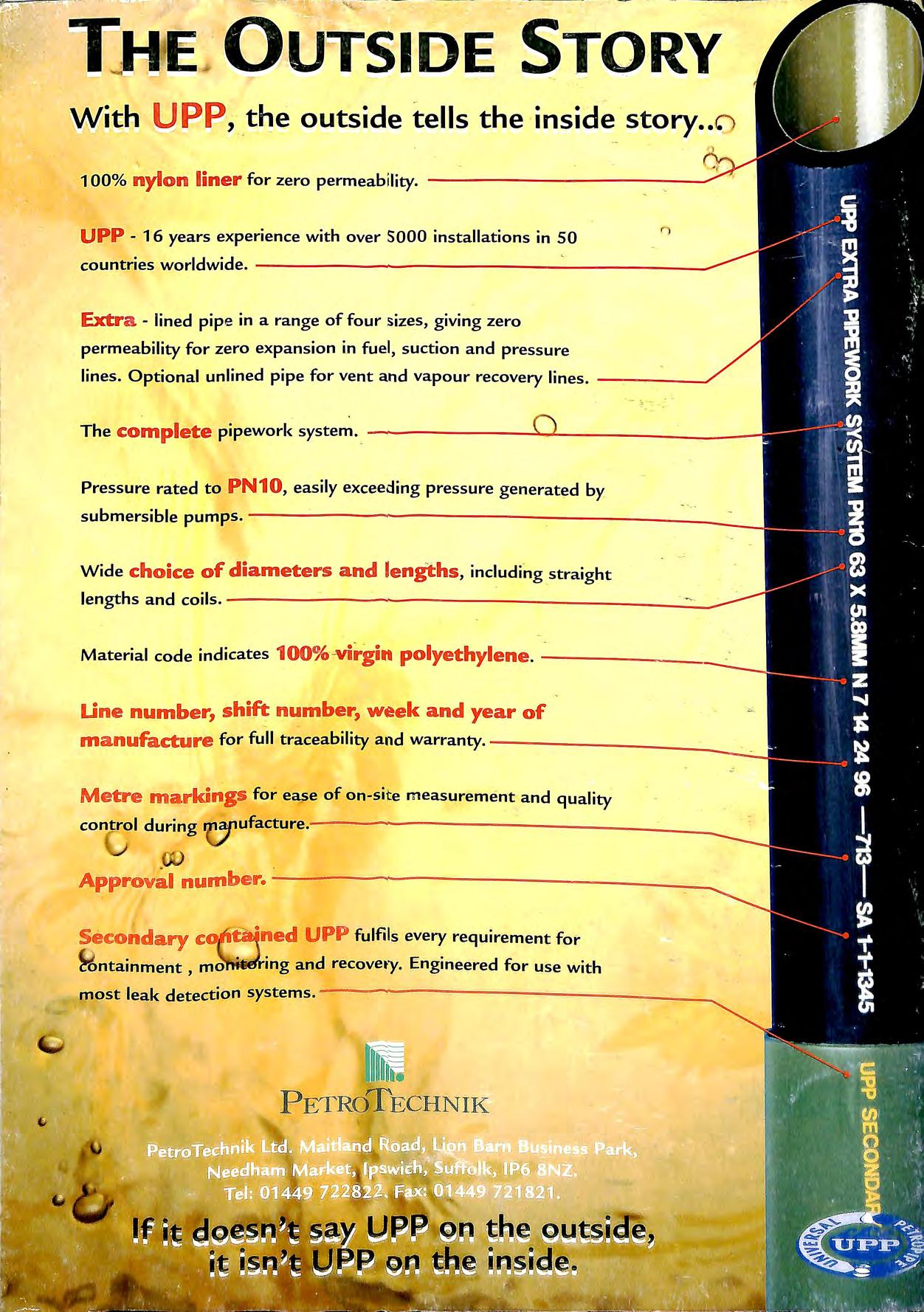
Pressure rated to PN10 , easily exceeding pressure generated by ... I ' submersible pumps. L 1 I • ...: .!!!;: Wide choice of diameters and lengths , including straight lengths and coils.
Material code indicates 100%-virgin polyethylene . ----------=-
t:.ine number, shift number, week and year of m a nufa cture for full traceability and warranty. Metre m a rkings for ease of on-site measurement and quality control during Secondary c::
. """
, · ·ned U PP fulfils every requirement for W, ntainment , mo ·ing and recovety. Engineered for use with most leak detection systems . -------------------PETROTECHNIK
