THE BULLETIN [ § ] ___ __ _ _, - J VOLUME 22 No 1 Journal (J , ' the AssQciatio,n for Pe,ro/eu:m an,d Explosives Admin';stratio·n
compact-able wastes Also static com(!Jac tBrs installed and serviced Skip services ((Jr the prefessional builder and 01 Y, enthusiast FIFTY YEARS OF SERVICE PROCRESS AND EXPERIENCE A modern fleet of tankers for dea(ing with general and special mdustrlal effluents Established services for domestic and farm cesspits and gully cleaning Jetting services fer Iiii and i fi1 Bustrial ;; c €J mmercial ::;--premises A 'Hotline' emergency service tor t he 'eu t of hours ' uneJ€peeted crises __ A Na :f./oj?w,rae specialist Tank OJean t ng Ser:vice IS WHA' YOU, GII' WITH CLEANSING SIR¥ICE GROUP HEAD OFFICE GRANGE ROA D SQ TL EV S032 GlD BOTliEY 223'2 R i NGWOOO 2OQ8 BRIISTO'L 552286 NEW,BUR V 45357 O XFORD 61160 EVESHAM 2620 STON,E f.lO USE 6 U a SE V ENQAKS 4$3175 MAR26A
B MMER TAB-LINK FOR LONGER LIFE EASIER SE RVI

During the past 2 years a different type of drive belt has appeared on forecourt petrol dispensers
The name IS Tab-Link, and its unique polyester/polyurethane construction enables this belt to last a minimum of six times longer than conventional V-belts.
It's easier to service, as one reel enables the service engineer to make up any length of belt to suit all pump assemblies, thereby greatly reducing the stock carried.
When it comes to the manufacture of pump equipment a simp!er design is possible USing Tab-Link, as the tensioning and sliding adjustment systems used with conventional drive belts aren ' t needed. , Tab-Link is in successful use in petrol I dispensers throughout Britain, including those ' serviced by Pump Maintenance Limited, and built by A very-Hardoll Ltd., Tokheim Ltd. and FerTaJ1ti Ltd.
BRANlNlE R I TABflllIiYJ!%. j So isn't it time yOLl fitted Tab-link you'll fand yourself in very good company BRAMMER TRANSM ISS IONS l uDo Hudson Road , Leeds LS9 7DF Tel (0532) 493486 Telex 556144 The driving force in pe t rol pump V-Belts!

Petrol tan k access chambersare they a problem ? - only Fibresec can solve it Fil;rC!sC!cl The new concept in manhole construction Tet: 0535 273091 0943 73221 for details
RETAIL
Design
MID BUCKS ENGINEERING LTD.

(Petroleum & Civil Division)
Members of the Association for Petroleum & Explosives Administration
Units 29 & 30, Rabans Close Industrial Estate, Aylesbury, Bucks., HP19 3RS
Telephone: Aylesbury (0296) 22039 & 34481
COMMERCIAL
& Installation of petrol, diesel, L.P.G. & lubricant storage and dispensing facilities
L.P.G. J
/'

INSTALLATIONS TO. CP' ---------------------------------------(Established 1968) Specialists in Petroleum Pipework Installations New and existing Tanks and Lines tested Modifications to existing Installations And all work associated with Forecourt Pipework 39 BROOK ROAD, RAYLEIGH WEIR INDUSTRIAL ESTATE RAYLEIGH, ESSEX SS67XN Tel: RAYLEIGH (0268) 781184 / 781859 (24 hrs ans.) The most comprehensive of petroleum equipment and related services is now available from one source: GILBARCO forecourt and commercial dispensing pumps and self service systems _ NORMONO electronic and ana logue output remote reading contents measurement sys t ems TlMEPLAN fuel management and security monitoring equipment _ S PEED WASH coin and token operated vehicle pressure washing systems _ OPW fuel dispensing nozzles and service station equipment _ Petrol and Diesel sotrage tanks _ SALES , SERVICE, INSTALLATION & MA INTENANCE ]i.".'''.'I'' Pump Services (UK) Ltd., Oakfield House, 60 Oakfield Road, Altrincham , Cheshire WA15 8EWTelephone 061 9414955 Tele)( 667834
£2.50 (Free to Members)
Published by the Association for Petroleum and Explosives Administration
Opinions expressed in this Journal are not necessarily the views of the Association
Contents
TALKING POINT NOTES & NEWS 1 2
ELECTROSTATIC HAZARDS IN HANDLING PETROLEUM PRODUCTS 4 TANK MANUFACTURERS VIEW 9
Talking Point
The Council of the Association has during the past year been working on an updated code of practice for petrol filling stations, it is hoped that this will be published later this year.
The code will reflect modem thinking and will be the result of close co-operation between industry and licensing authorities who have been representative on the council. This will be the first practical code to have been published in an updated form for 16 years.
Honorary Secretary
Mr. E. Brown ambridgeshire County C 'I B ounCI, i
Editor M r. J. A. J. Thompson,
ISSN 0263-4597
VOLUME 22 Number 1 JANUARY, 1984 The Bulletin
Honorary
SNOOKERED BY STAUNCmONS
In its current redevelopment programme Esso Petroleum are developing a large number of self service sites throughout country in a new image, which in design is very attractive WIth clear modern lines, and colour and graphics carefully chosen to project a corporate image not only throughout the UK, but which will be seen in other countries. The Esso Retail Concept or ERIC for short have large canopies bemg supported by unusually large canopy staunchions of almost 1m wide. In certain circumstances this is causing problems by obscuring the pumps from the console position, contrary to a self service condition. The Home Office Model Code 2-5-2 All If " .,. se servlcepumpsshouldbeclearlyandreadily VISible from the control point.
hiEsso Petroleum spokesman has informed The Bulletin that t s problem is not being encountered nationwide only at in the South East. He felt that the letter of law was mterpreted and not the spirit of the law the company policy was that 't r I . . ' I le t It was more Important to see the operator and not the H b pump. e confirmed that where objections had een raJsed by I" h ICensmg aut orities the company have managed to rea ' b" rrange to 0 tam satisfactory VJewmg.
While the Code th I may not agree with the Home Office e nstItute of Petroleum Marketing and Safety Code is more explicit· "All d di serv' h'- pumps an 'spensers for attended self v' t ould be located so that they are at all times clearly DISI ehirom the control point, and so that no obstacle except bort ve des being fuelled, is liable to be placed or come e ween the d' thi ISpensmg area and the control point." Perhaps s was not Con .d d h E SI ere w en ruc was being conceived.
INSPEcrIONS FALL
In a recent q t' m · ues Ion time m the House of Commons the mIster Mr S I facto I' e wyn Gummer revealed that the average d expect a visit from the Health and Safety once every seven years.
Answering q t' numb f . ues Ions m the house he explained that the er 0 Illspe t' h d I <)() ()()() c Ions a dropped from 216,000 in 1980 to " m 1<)82 Thi prem' f . s was despite a rise in the number of Ises fOm ;·l(}9,OOO to 500,000.
Answering f th visits d ur er questIOns he showed that the number of betwe mal by factory inspectors dropped by over 30% 8'12 [en 0 and 1!J82. As at December 1st 1983 there were , actory inspe t . I !184 Wh'l c ors m post, and no increase is forecast for alloc't' I e expansion of the HSE was planned in 1979 no a Ion Was m d t . , a e 0 Illcrease the factory inspectorate. i'actofY In 1!l70 1!l71 I I Iq7+ 1(17.) I (}7f> Iq;; I'I,X 1'1;11 I'IX() I'IXI "IX!
spector VISitS 1!l70 to 1!182 274,000 27!J,OOO 24/i,OOO 20/i,OOO :201,000 I !14,OOO 18S,OOO I 20!I,OOO "l. 1.>,000 L. J (i,OOO "l.O:·l,O(JO I !jO ,000
CONTROLLING STATIC ELECTRICITY
Static electricity has been deliberately harnessed with great success in some manufacturing processes such as paint spraying. But when it occurs as a side effect, as happens in many industrial operations, there is a very real danger of fire or explosion owing to electrostatic discharge, particularly in petroleum or chemical plants. There may also be operational problems during manufacture and handling as a result of particles adhering to each other or attracting dust.
Comprehensive guidance on these and other aspects of static behaviour are provided in a new BSI code of practice, BS 5958 Control of undesirable static electricity Part 2 Recommendations for particular industrial situations. This provides recommendations for controlling specific static problems associated with the handling of different types of materials including liquids, powders, gases, sprays, explosives or electro-explosive devices. Part 2 emphasises that electrostatic hazards seldom occur in isolation and that precautions against static electricity should therefore be consistent with those taken to avoid other hazards such as ignition due to other causes, or toxicity. Particular care should be taken in the provision of earthing arrangements where these may interfere with other protective systems (egcathodic protection or intrinSically safe electrical equipment).
Part 1 of the code, which was published in 1980, provides basic information on the generation of undesirable static electricity in solids, liquids and gases, and describes how the subsequent discharge may cause ignition or electric shock. It also deals with the principles of earthing and bonding used to avoid the electrostatic and offers guidance on the means of measuring or estimating the parameters that should be taken into account when deciding upon suitable countermeasures.

New Members
notes &
news
The Association welcomes the following new members Invicta Pipework (South East) Ltd., Mr. P.B. Hale, Mr. F.M.C. King, Mr. W.D. Harkness, Mr. F.H. Day, Mr. R.I. Wilson,
Manager,
DR YLINE METERING SYSTEM
January 1984 heralds the first birthday of the new Dryl· M . S etenng ystem 87.
It was twelve months ago that the first Dryline System to meet the new Weights and Measures regulations (1830) was fi tted to a road tanker, and one year on is working as well as on the day it was fitted.
Sinc: those early days the new Dryline System has been recogrused as the approved alternative to 'wet' line delivery. Until 29th October 1982, the date on which the Certificate of EEC Pattern approval of a measUling instrument was issued to J h · H;idt the oil industry had no alternative to t e wet me e ivery after I st July 1984.

The Dryline 87 has the unique quality of providing a method of th.at allows those companies who wish to operate a drylme delIvery system to continue vvith their accepted normal procedures, with only slight change !I1 dnver operatIOn when making deliv eries.
The advantages of a Dryline System are numerous, and come into their own where mUlti products are required to be
delivered same vehicle loading, considerably reduced possibilItIes of contaminated fuels being delivered to customers, no I.ine chasing on change of products, no heavy hose reel for driver to pull out (and therefore no extra weight on rewind motors), no off-set fill valve required on customer inlets as Dryline System enables blowing out of delivery lines, and, for those A.D. operating from Customs & Excise bonded major terminals, no problem of 'wet' line products in the system not being compatible with fuels required for delivery after re loading, i.e. gas oil in line with a full load of DERV to deliver next.
Our Dryline System, having EEC Pattern approval, is, once fitted and stamped 'E' By Trading Standards, approved until October 1992. This is a significant point worth bearing in mind as some delivery systems are only receiving National Stamping which is only valid until 1st July 1987. After this date all systems have to be EEC Pattern approved. Do you need to spend your money twice? If not then it is 'E' stamping for you.
Our Dryline System 87 can be fitted to existing vehicles having either Neptune or L C Meters with catherine type hose reels, and within the next few months should be available for other popular makes of meter. An increasing number of complete systems are being supplied to Tanker Builders for new vehicles. This equipment can easily be transferred when in later years remounts are required at chassis changes. The equipment in the system can easily last for two or more life times of a vehicle
To prevent an operator from holding a full hose reel line of product (fraud) the new regulation (1830) for a Dryline System stipulates that th e empty hose must not have a closure. Our System is designed in such a way that no closure is required in the nonnal operation of delivery. Instruction is given to operators on how to handle all types of delivery and thus comply with the new regulations. When operators observe the correct procedures no spillage occurs and if necessary the hose can be placed on the ground and no residue product will run out.
j. Heidt Developments give YOU the choice, we strongly advise that you contact the company at Hoobrook Trading Estate, Worcester Road, Kidderminster for full details w ell in advance of the July deadline. The contact at th e company is Phil Darbyshire on STD
Mr. j.C. Horsburgh,
Mr. M . Pindar, C. Sweating, Trading Standards Dept. j.C.S. Oehley Engineering
:l
Electrostatic Hazards and their elimination in the handling of Petroleum Products
 Dr. H. Walmsley, Shell Research Ltd
1. INTRODUCTION
Explosions and frres initiated by electrostatic sparks may ?ccur in a wide variety of circumstances in the petroleum Industry. Processes that have known to produce ignitions include loading road or rail tankers, refuelling aircraft, stirring reaction vessels and washing the tanks of very large crude Carriers. These ignitions can be both dangerous and expensive and it is clearly important to prevent them. Statutory requirements designed to prevent ignitions have been developed by a number of bodies. Therefore, rather than presenting quantitative rules for the avoidance of hazards I will, in this paper, explain the backgrounds to those rules that affect the petroleum !ndustry. To do this I will demonstrate in general terms how electrostatic ignitions occur and then three typical petroleum handling operations shOwing In .each case how the ignition conditions could be met and how this possibility can be avoided. Finally I will summarise the that can be taken, indicating for each one both its hmItations and the circumstances under which it is most appropriate.
2. PROCESSES LEADING TO AN ELECTROSTATIC IGNITION
For conditions must be satisfred before an electrostatic ignition can occur. These are:-
(I) Charge must be generated
(2) Charge must accumulate
(:-l) An incendive spark must occur
(4) A flammable mixture must be present at the spark
I will now discuss in general terms the processes that lead to these conditions being met.
2.1 Charge generation
Charge is generated whenever solids or liquids move in to one another. In the petroleum industry we are mamly, though not exclUSively, concerned with the charge produced at solid/liquid interfaces. A layer of charge is produced on the liquid side of all such interfaces either by chemical reactions or by the adsorption of ions onto the wall :rom the liquid (small numbers of ions are present as Impurities even in apparently non-ionic liquids such as fuels). DUring pumping operations the II1ter/acial charges are tranpsorted by the flow, resulting in an plectJic CWTent called the "streaming current". Streaming currents can be several tens of microamps under adverse ('()nditions. Sometimes charge generation is described in [PIms of charge dC'nsity rather than a streaming current. The chilrw' denSity is simply the streaming CUlTent divided by the \(JJ UIlIP no",.. rate' and maybe several hundreds of 1l1l<T()(()ulombs per cubic metre. Charge generations is IJlg/wsl with rapid flows and large interfacial areas and is I/ww/()/'I' particularly associated with fine filters, nozzles, 'f If Cl '. I I\( J plwsp 111;xtures and high throughpu t systems.
2.2 Charge accumulation
The charges produced by flowing liquids generate potentials that tend to return charge to ground. This return may occur in a non-hazardous fashion by conduction throu?h the liquid itself or through earthed conductors in contact WIth the liquid. If, however, the resistance to ground is excessively high, charge will accumulate, the potential will rise and return to ground may occur via an electrical discharge. A high resistance may occur because the liquid is surrounded ?y insulating material, because the conductors in contact WIth the liquid are isolated from ground, or because the liquid itself is insulating. A resistance to ground of less than 106 ohms will keep the potential below 100 volts even for the highest streaming currents that can be produced (several tens of microamps). In most cases, however, charge is generated much more slowly and much higher resistances can be tolerated. The resistance can usually be kept adequately low by earthing conducting components, incorporating conducting elements into insulating materials and by using anti-static additives in liquids. Charges stored on aerosols are, however, diffrcult to diSSipate.
2.3 The production of incendive discharges
Electrical discharges may, or may not be incendive. For our purposes we need to consider the incendivity of three different types of discharge, namely, those that occur between two conductors, those that occur between a conductor and an insulating surface and those that occur between a conductor and the surrounding atmosphere.
(a) Discharges between conductors
These form narrow sparks of short duration ( 0.1 us) and they discharge most of the energy stored on the conductors. They if the discharge energy is more than the mIrumum IgrutIon energy (MIE) unless quenching effects values fO.r several hydrocarbon vapours in air are gIven In Table 1 and It can be seen that most are just above 0.2 mJ. The energy stored on the two conductors is given by 1n where C is the capacitance between them and V the potential difference. Generally C will be less than lO-!J Fin which case the stored energy is less than 0.2 mJ when V 600 V. Usually, however, a more conservative approach is taken and potentials above 100 V are regarded as hazardous.]
(b) Discharges between conductors and insulating surfaces.
These are called brush discharges and they are much more diffuse than sparks between conductors *(Brush and corona discharges are more incendive when the insulator/ atmosphere is negative. The limits given here are for this more .As a result they need to be more energetic Igmte a glVen,mlxture. Empirically it is found' that brush discharges transferring more than about HO nC of charge are capable of iptiting hydrocarbon vapours. ,', This level of charge transfer has been associated with potential of around 40 kV between the condustor and the insulating surface. ,.
(c) Discharges bet"veen conductors and the surrounding atmosphere.
These can broadly be classed as coronas. They are even more diffuse than brush discharges and consequently are incendive only at very high potentials ( 70 kV)."
Since sparks between conductors are the most incendive. safety is greatly enhanced by bonding all conductors to ensure that they are at the same potential.
2.4 The presence of a flammable mixture
For a mixture to be flammable it must have both sufficient oxygen and an appropriate amount of fuel vapour. The concentration of vapour produced by a given fuel depends on the vapour pressure and hence on the temperature. Approximate temperature ranges over which some fuels give vapours that are flammable in air are shown in Figure 2. At normal ambient temperatures, low volatility fuels such as kerosine or gas oil that are well below their flash points give too little vapour to support combustion whereas high volatility fuels such as gasoline give too much. In many cases, however, fuel vapour can be present in flammable amounts. When this happens, the mixture can still be rendered nonflammable by replacing the air with an inert gas. In this context an "inert" gas is one whose oxygen content is too low to support combustion. For hydrocarbon vapours, gases containing less than 8% oxygen may be regarded as inert.
3. SOME PROCESSES IN WHICH ELECTROSTATIC HAZARDS MAY OCCUR
I will now consider the existence and control of potential electrostatic hazards in three types of operation. In each case I will show how the four ignition conditions can be met and then discuss the methods that can be adopted to eliminate the hazards. The three types of operation are:
(1) filling road tankers with liquid hydrocarbons
(2) refuelling aircraft
(3) washing crude oil tanks on shipes (VLCCs)
3.1 Fill road tankers
Road tankers carry hydrocarbon liqUids in compartments of up to Sm1 in volume (this may soon be increased) and the compartments are loaded at rates of up to about 2m3lmin. Charge generation occurs in the components (pipes, meters etc) of the fuel handling system and the currents produced are typically of the order of microamps. Accumulation can take place on the tanker in two ways. The first occurs when the vehicle is electrically isolated from ground (with currents of the order of microamps, resistances of more than 10" ohms can be considered isolating), The charge carried by the incoming fuel can then raise the potential of the vehicle sufficiently to produced incendive two-conductor sparks between the tanker and any nearby earthed object. Since flammable vapours may be present where tankers are loaded these sparks could produce ignitions.
The second form of accumulation occurs when the liquid itself is insulating, Charge may then accumulate on the liquid inside a compartment even though the compartment is conducting Brush discharges may be produced, between ,the hqllid surface and projections on the tank root such as stlffeners or level gauges, Also if an isolated conductor, such, as an unbonded sample can, is introduced it could acqUIre charge and produce a two-conductor spark to the tank walL
tankers are dedicated to the transpurt of fuels such as gas Oils that have a low vulatility. These operations art:'
relatively safe since flammalbe mixtures should not be present inside the tanks. Sometimes, however, "switch-loading" occurs. This involves loading a non-volatile fuel into a tank. that has previously contained a volatile product such as gasoline. During switch-loading a flammable mixture will, at some stage, be present in the tank and the operation is thus vulnerable to electrostatic ignitions. Volatile products that produce over-rich vapours can be loaded relatively safely but over-richness cannot be relied upon to safeguard loading completely since the mixture will only be over-rich everywhere in the tank if an adequate equilibration is allowed and if there is adequate mixing. Thus for sWItchloading and loading volatile products it is necessary to take precautions to avoid incendive brush discharges within the tank. The same precautions are in fact applied to the normal loading of non-volatile products because it is not always possible to be sure of the tanker's history or the absence of volatile components in the fuel.
To prevent sparks between conductors it is merely necessary to ensure that the vehicle or any equipment that may be introduced into the tank is securely earthed. Any resistance below about 10" ohms would give adequate protection but it is easier to check lower values so in practice an earth resistance of less than 10 ohms is specified. l
Two techniques are available to prevent incendive brush discharges. One is to limit the rate of flow of product other is to increase the conductivity using an antI-statIC additive. The flow rate limit has two effects, firstly it limits the charge density of the liquid entering the tank and se:ondly it increases the time required to fill the tank thus allOWIng more time for charge to decay. Increasing the conductivity reduces the time required for the charge to decay (for all purposes this "relaxation" is where 0 the electrical conductivity of the lIqUId m pSm ). The flow rate and conductivity restrictions can be applied s:parately or together. For non-aviation products a conductlvlty.above 10 pSm- l may be considered safe for the flow rates enVIsaged on present-day systems. When doping is She!l's practice is to dope to such a that SO pSm at the m.l is ensured. It is worth notmg that the use of antI-statIC additives does not eliminate the need to bond all conductors.
:i.2 Refuelling aircraft
The problems encountered in refuelling aircraft are essentially the same as in truck fIlling and th,ey have been tackled by the same methods, namely bondmg, flow rate limitation and conductivity enhancement. An extra appears in aviation fuel handling, because of use, of microfiIters to ensure fuel deanlmess. Mlcrofilters consIst oi aper elements containing numerous small pores. These Present a large surface area to the fuel and hence generate krge amounts of charge. The produce in a may be up to two orders of magmtude than that m a and as a result, the precautions evolved to contal11 the nsks are more restrictive than those delived for roadtank filling, In the past, attempts to tlw hazard by f1l.)\\ rate limitation, bv careiul deSIgn of tank mlets and by passmg the fuel tanks ("relaxation chambers") that held it for long enough to dissipate the excess charge. None of these \\ as completely successful, hmH'ver, and it is nO\\ general" accepted that the best wa\ to ensure tht' safe handling ori et fuels is tu use an anti-static additiyt' to raist' thl' nmducti\'it \. A conductivit v of mort' than ,j() pSm is nOllnalh ctlnsiderpd to be nl'cessal'\ at the fill point. To achit'\l' this. a spt'l'ifiultitlll of I 70 ± ,j() pSIll a t I ,j"(' is adhered to.

.l
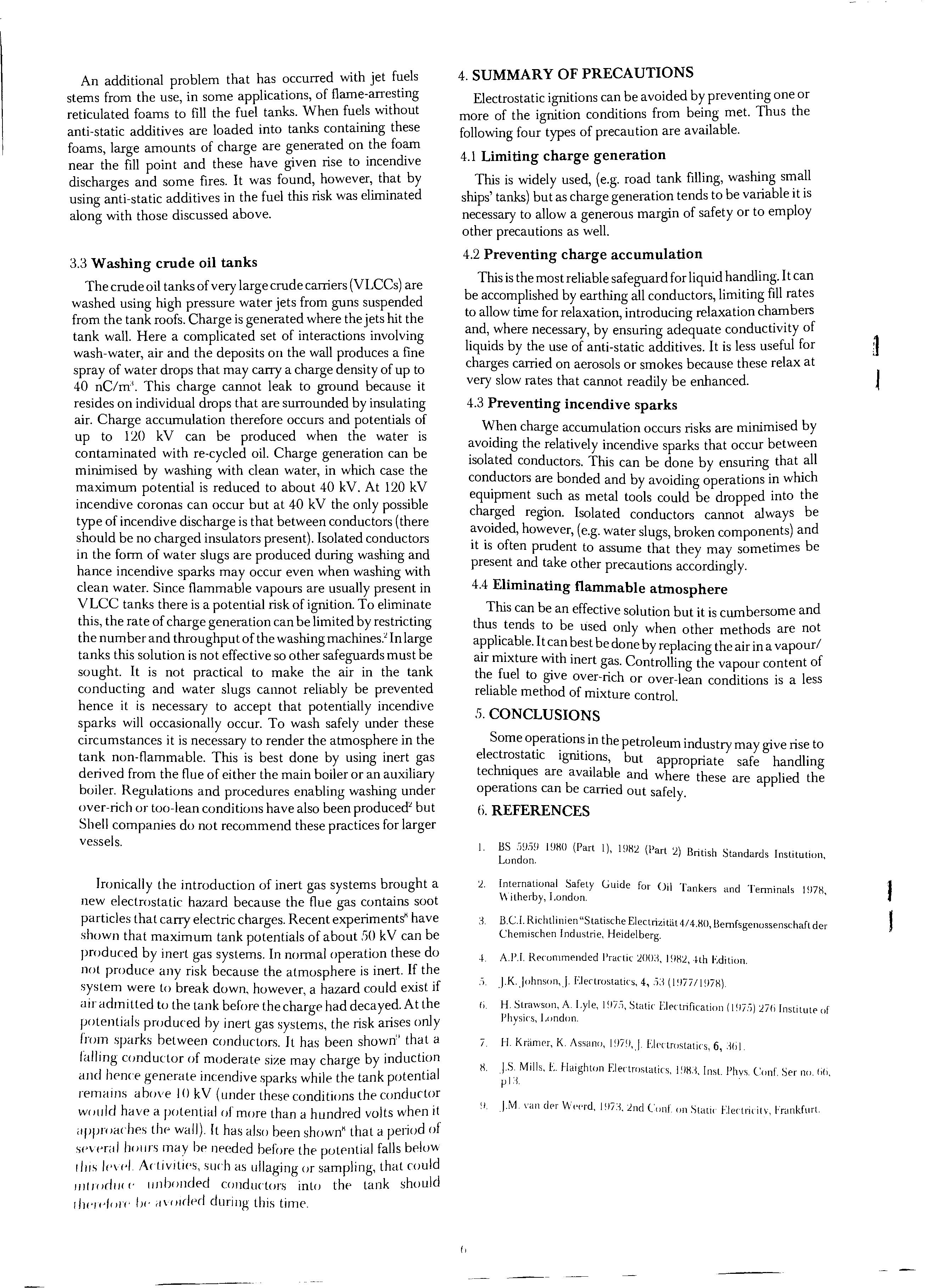
An additional problem that has occurred with jet fuels stems from the use, in some applications, of flame-arresting reticulated foams to fill the fuel tanks. When fuels without anti-static additives are loaded into tanks containing these foams, large amounts of charge are generated on the foam near the fill point and these have given rise to incendive discharges and some fires. It was found, however, that by using anti-static additives in the fuel this risk was eliminated along with those discussed above.
3.3 Washing crude oil tanks
The crude oil tanks of very large crude carriers (VLCCs) are washed using high pressure water jets from guns suspended from the tank roofs. Charge is generated where the jets hit the tank wall. Here a complicated set of interactions involving wash-water, air and the deposits on the wall produces a fine spray of water drops that may carry a charge density of up to 40 nC/m'. This charge cannot leak to ground because it on individual drops that are surrounded by insulating air. Charge accumulation therefore occurs and potentials of up to 1'20 kV can be produced when the water is contaminated with re-cycled oil. Charge generation can be minimised by washing with clean water, in which case the maximum potential is reduced to about 40 kV. At 1'20 kV incendive coronas can occur but at 40 kV the only possible type of incendive discharge is that between conductors (there should be no charged insulators present). Isolated conductors in the form of water slugs are produced during washing and hance incendive sparks may occur even when washing with clean water. Since flammable vapours are usually present in VLCC tanks there is a potential risk of ignition. To eliminate this, the rate of charge generation can be limited by restricting the number and throughput of the In large tanks this solution is not effective so other safeguards must be sought. It is not practical to make the air in the tank conducting and water slugs cannot reliably be prevented hence it is necessary to accept that potentially incendive sparks will occasionally occur. To wash safely under these CIrcumstances it is necessary to render the atmosphere in the non-flammable. This is best done by using inert gas from the flue of either the main boiler or an auxiliary boiler. Regulations and procedures enabling washing under or too-lean conditions have also been but Shell companies do not recommend these practices for larger vessels.
Ironically the introduction of inert gas systems brought a new electrostatic hazard because the flue gas contains soot particles that carry electric charges. Recent experiments" have shown that maximum tank potentials of about!iO kV can be produced by inert gas systems. In normal operation these do not produce any risk because the atmosphere is inert. If the system were to break down, however, a hazard could exist if all" admitted to the tank before the charge had decayed. At the potentmls produced by inert gas systems, the risk arises only fmm sparks between conductors. It has been shown" that a falling conductor of moderate size may charge by induction and Iwnce generate incendive sparks while the tank potential rermtlns above I() kV (under these conditions the conductor wOllld have a potential of more than a hundred volts when it "ppmaches tlw wall). It has also been shown" that a period of several how"s may be needed before the potential falls below flrrs l('vel Adrvrtl('s, such as ullaging or sampling, that could lilt ]OdlJ(l' Ilnbonded conductors into the tank should t/WW/Oj(' Iw (/v()ldec\ during this time.
4. SUMMARY OF PRECAUTIONS
Electrostatic ignitions can be avoided by preventing one or more of the ignition conditions from being met. Thus the following four types of precaution are available.
4.1 Limiting charge generation
This is widely used, (e.g. road tank filling, washing small ships' tanks) but as charge generation tends to be variable it is necessary to allow a generous margin of safety or to employ other precautions as well.
4.2 Preventing charge accumulation
Tills is the most reliable safeguard for liquid handling. It can be accomplished by eartillng all conductors, limiting fill rates to allow time for relaxation, introducing relaxation chambers and, where necessary, by ensuring adequate conductivity of liquids by the use of anti-static additives. It is less useful for charges carried on aerosols or smokes because these relax at very slow rates that cannot readily be enhanced.
4.3 Preventing incendive sparks
charge accumulation occurs risks are minimised by the relatively incendive sparks that occur between Isolated conductors. This can be done by ensuring that all are bonded and by avoiding operations in willch eqUipment such as metal tools could be dropped into the region. Isolated conductors cannot always be however, (e.g. water slugs, broken components) and It IS often prudent to assume that they may sometimes be present and take other precautions accordingly.
4.4 Eliminating flammable atmosphere
This can be an effective solution but it is cumbersome and thus. tends to be used only when other methods are not applicable. It can best be d b l' . . / one y rep acmg the aIr m a vapour aIr mIxture with inert ga C 11' f h f l' s. ontro Illg the vapour content 0 t ue to gIVe over-rich or over-lean conditions is a less reliable method of mixture control.
!i. CONCLUSIONS
Some operations in th t 1 . 1 '" e pe ro eum mdustry may give rise to e ectrostatJc Igrutions b t . t h' . ' u appropnate safe handling ec are bavaIlable and where these are applied the opera Ions can e carried out safely.
6. REFERENCES
I. BS :iD.'''! 19HO (Part I), I (Part :i) B h S London. ntts tandards Institution,
International Safety Guide for UI T k . " Witherby, London. I an ers and I ennmals I !l7H,
3. B.c.l. Richtlinien"Statische Electrizitat4/4 I' f Ch . h .0 >ern sgenossenschaft der cmlsc en Industrie, Heidelberg.
4. AY.!. Recommended I'ractic I Edition.
.> JK..Johnson,J Electrostatics, 4, .i3
Ii. H. Strawson, A. Lyle, I!l7';' Static Electrification (I !l7."» L7b Insti f PhYSICS, London. tllte 0
I. H. Krtimer, K. Assano, 1!J7'I,J EIl'clroslatirs, 6, :,(;1.
H. JS Mills, E. f-laighton Electrostatics l'IX1 I It PI . C f S pl:1. ., , IS. lYs. on er no. 1;li,
!!. I·M vall del' Wel'rd, 1'!7:, L IC· f· .., ne ()ll on Statl< f.lectnClty, hankfurt.
(,
J J
SOLID
+ Excess charge adsorbed on wall (adsorption charging) .x election defIcIt near surface of metal (reaction charging)

Excess (negative) charge in bulk liquid
Fig. 1 Charge generation by a solid -liquid interface
TABLE 1
Minimum spark ignition energies of some explosive mixtures, mJ
Methane/air 0.:29
Propane/air 0.:25
Heptane/air 0.:23
Benzene/air 0.:20
Diethyl ether/air WlO
Propane/oxygen o.om
Hydrogen/air (l.Ol-l
LIQUID
7 L

100 l TOO RICH MOTOR GASOLINES 10 -40 AVIATION GASOLINES -:,W JET B UP4) , ;.,.., g '" o FLAMMABLE :.:::: :e 1.0 ..r ::J ':fl ':fl :0'-' :0.. < > V APORISING OILS Cl t;:l :>:: JET A,JET A I KEROSINE 0.1 liO [ T()() LLAN I .11'.:;' GAS OILS FUEL OILS __ L _____ -L------.L _____ ...J..._____...J, 0.01 I /,11 LO () LO li() I'EMI'I·Jt\Tl·RE. T hg I \/l/lr" Xl/lIil te relationship bet weeIl volatilit y olpetroleum products and flammability of equilibl;um vapour/air mixtures.
HE ANK MANU FACTURER'S VIEW
B.J. Caines, C.Eng., M.I.Mech.E., M.I.Prod.E.
INTRODUCTION
The purpose of this paper is to examine some of the problems encountered with the installation and testing of underground fuel storage tanks together with possible solutions. Also included is a brief look at developments in design and manufacture of tanks.
PROBLEMS
Tank Distortion. It is commo n practice to hydraulically test tanks in the excavation prior to infilling and leave the water in th e tank to resist buoyancy. The mechanics of this operation are not fully understood by many installers with the result that large tanks are positioned on the base slab a nd filled with water without any additional support.
The weight of water in say a 12,000 gallon tank approaches fiO tons and under these circumstances this force will be concentrated on a very small area of the tank bottom which wi ll offer little or no resistance to flatt ening This flattening itself will not cause tank failure and may not even be noticed during installation but very often becomes apparent when dipstick readings are inaccurate as the calibration will be invalid for that shape tank.
Small tanks 15' long or less can be tested in this way as th e dished ends have a stiffening effect on the shell however larger tanks must be supported in a similar way to an above ground tank. Methods of support that can be used are: concrete cradles, mild steel cradles, temporary wooden chocks or supports or concrete part bed.
Another ca use of distortion encountered is where the installer, to level the tank, has packed an end or part of th e tank on bIicks or blocks which will again concentrate the majority of the water or product load on a small area of the tank causing local distorti o n.
Tank Buoyancy. When installing an underground tank, holding down straps are required for two main reasons:
a) To resist th e buoyancy effect of the tank trying to float upwards on the liquid concrete at the infill stage or any water that ma y be in th e excavation from rain or SItes WIth a high water table.
b) To resist the tank moving out of position horizontally during the operation of infilling with co ncrete.
The buo ya nc y effect is often avoided by leaving the hydraulic test water in the tank but where this is not the case, th e forces resulting can be considerable for example a 12,000 gallon tank has a potential upthrust of 5 1.6 tons which is eq ual to the weight of wate r displaced less th e weight of the tank.
Many tank manufacturers supply ho lding do wn straps manufactured from mild stee l flat secured to the conc rete base by cast in stirrups and jOinted at th e top with a bolt. The weakest part of this assem bl y is th e joining bolt whi ch hmIts th e strengt h p er holding dow n strap assembl y to appro x. tons dep e nding upon bolt size. Co nsequen tl y this type o f strap ca n only be used fo r loca ting purpos es as It IS unpractIcal to us e suffic ien t numb ers to resi st full buo ya nc y e ffec ts
It is the practice of some installers to use steel wire ropes or hawsers tensioned b y turn buckles to resist the buo yancy effect but th ese can be difficult to handl e and adjust together with causing high local loads on the tank in question and damaging paint work. The hawser syst:m also requires cast in stirrups as per the flat bar holdmg down straps.
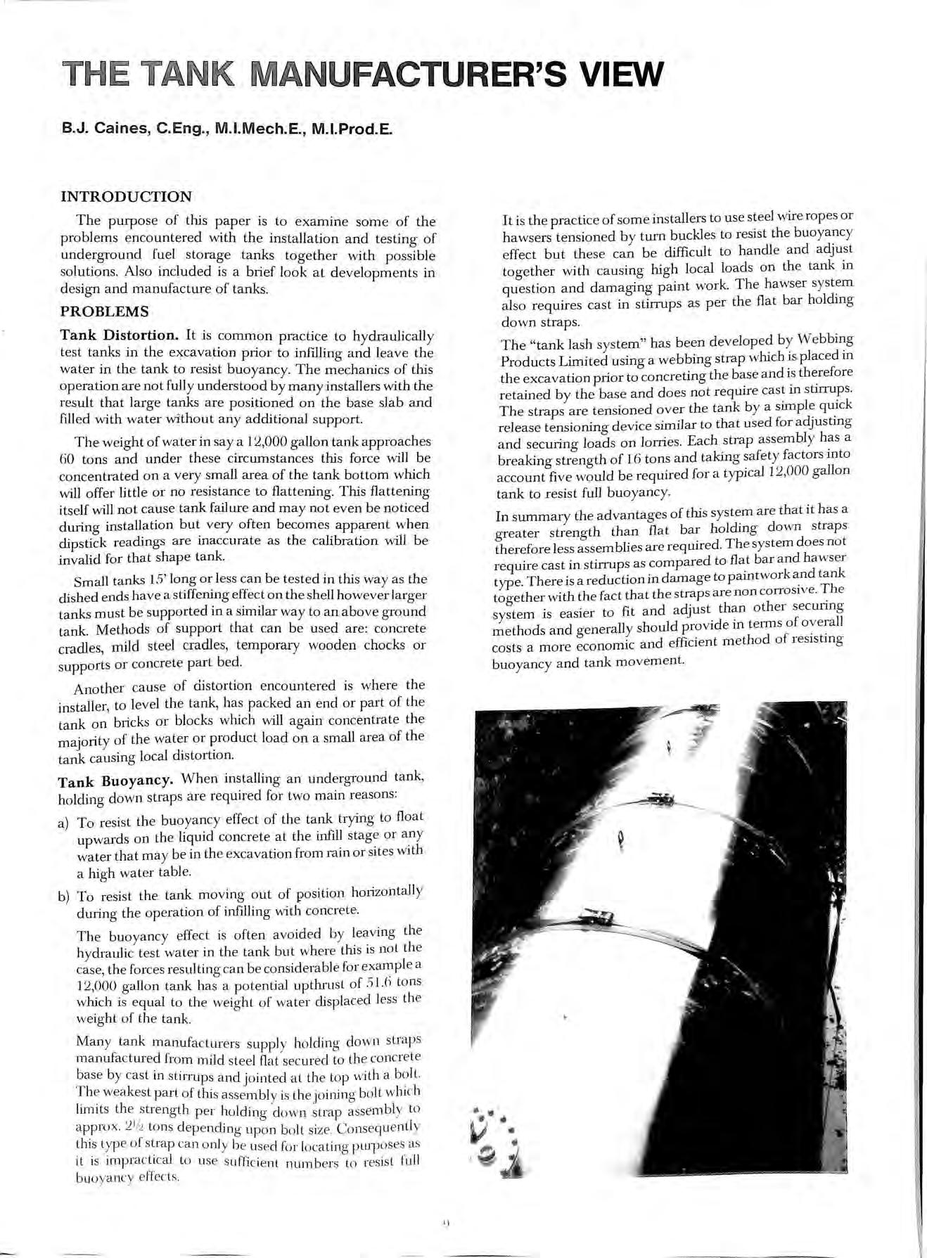
The "tank lash system" has b ee n by Prod ucts Limited using a webbing strap which IS placed m th e excavation prior to concreting the base a nd is therefore retained by the base and does not require cast m st!ITUps. The straps are tensioned over the tank by a slII1ple qU.lck release tensioning device similar to that used for adJustmg and securing loads on lorries. Each strap as sem bly has a breaking strength of 16 tons and taking safety factors mto account fiv e would be required for a typical 12,000 gallon tank to resist full buoyancy.
In summary th e advantages of this system are that it has a grea ter strength than fl a t bar holding down straps therefore less assembl ies are required. The system does not require cast in stirrups as compared to fla.t bar and haws er type. There is a reduction in damage to pamtwork and tank together with the fact that the straps are non cOITosive. system is easier to fit and a djust than other secunng methods and generally should provide in tenns of overall costs a more eco nomic and efficient method of reslstmg buoyancy and tank movem ent.
)

BS2594 MANUFACTURING TOLERANCES
Ir '/ - ---_ _---- -_. '. \ V CIRCULARITY 1% MAX. INSTALLATION LEVEL ERROR J :Wmm LEVEL ERROR f - - ----T1\ /\ EXAMPLE CALIBRATION ERRORS FROM 1200 GALLON TANK (NOM 9' DIA. x 30') MAX CONDITIONS FROM MANUFACTURING TOLERANCES AND MINOR INSTALLATION ERROR. READING ERROR SOURCE ERROR (%) LITRES GALLONS DIAMETER TOLERANCE (J..'>I '277 61 CIRClJLARITY T( )LERANCE
LENCTH TOLERANCE 0.:)
10mm LEVEL ERROR
"nnALS
1--.-. 10
LENGTHO.5'};.
'2.53 @] ]5'2
'273 (iO
1.7H 4-H(i 107
:)3'2 11'27 :-lHO
Dipsticks. One of the most frequent causes of user dissatisfaction is inaccurate dipstick readings as compared to tanker delivery figures. Most tank manufacturers supply commercially pre-calibrated dip rods which despite a warning in (clause 11.1) are misunderstood by many users.
A commercially pre-calibrated dipstick is based on a computer calculation of the nominal tank dimensions however, as tank manufacture is not a precise practice and the British Standard allows certain tolerances, if these tolerances are in the extreme upper or lower limits, they can have dramatic effect on dipstick accuracy.
Another contributory factor is the level of the installed tank which in civil engineering terms may not be critical but can have serious effect on dipstick accuracy.
To illustrate this point, appendix (A) shows the calculation for a 12,000 gallon tank where it can be seen that manufacturing tolerances and minor installation errors can result in a 5.32% error on dipstick readings. In practice some ofthese errors may be cancelled but the accuracy ofa pre-calibrated dip rod whilst being proportional to the length of the tank cannot be claimed to be more than 5%.
When investigating the problems with dipstick accuracy reading differentials of less than 5% can usually be put down to the foregoing but errors in excess of this figure could mean the wrong dipstick being used or tank flattening has occurred as in 1 and this should be investigated by checking the dipstick length when engaged with the tank against nominal tank diameter plus manhole and dip fitting. If dipstick accuracy is required then specialist calibration must be used either by precise internal measurements or volumetric fill methods but both of these techniques result in a considerably higher cost than the commercially pre-calibrated dip rod which is still the most widely used basic method of measuring tank contents.
FUTURE DEVELOPMENT
The obvious future trend is towards improvement of product quality with particular regard to environmental hazards and longer product life. Increasing installation and reinstallation costs are gradually inducing tank purchasers to consider the use of improved materials and manufacturing techniques. It is not a question of a requirement for extensive research and development work as the technology and materials are in existence to design and manufacture tanks of almost infinite life. The only limitations being economics.
It is also interesting to make observations of developments in other countries which could influence future UK practice:-
Materials of Construction
Traditionally mild steel has been used for petroleum storage tanks as despite its to corrosion, it is more cost effective than corrosIOn reslstmg steels such as the stainless ranges which can cost up to ten times as much per ton.
However a new material known as Cromweld :-lCR 12 has recently been developed in South Africa which has a.price approx. half way between that of mild steel and steel but has similar corrosion resisting propertIes to stainless. At least one major UK petroleum company is considering the use of this material for underground tanks particularly in acid soil conditions.

The early promise of fibreglass materials has not been fulfilled to date due to the high cost and low mechanical strength of this material.
Methods of Manufacture.
BS2594 clause 9.6.2 allows 25% maximum plate missaligrIffient during tank manufacture. This misaligrIffient has a significant influence on tank life as the effective tank thickness is reduced by the degree of misaligrIffient of adjacent plates. Modern semi automatic tank assembly machines reduce plate misaligrIffient to a minimum by spreading evenly any circumferential difference on adjacent place throughout the whole circumference. Improved weld quality can also be obtained from the use of the automatic submerged arc welding heads which are an integral part of the tank assembly machine. With double sided submerged arc welds excellent penetration is achieved with a resultant quality close to that of pressure vessel welds.
Methods of Protection.
Double skinned tanks are widely used in Germany with a primary tank of similar construction to that in U.K but this tank is contained in a secondry skin. There IS approximately one plate thickness gap between the. two tanks whch is filled with a chemical that reacts to gIve a change in electrical characteristics if a leak should occur from the inner tank. Although these tanks are manufactured by semi-automatic methods,. they are obviously more expensive in constructIOn than conventional. In the writer's opinion, the expense of the secondary skin would be better employed in improving the primary containment.
There are a wide range of coatings available for. the protection of both tank internals from condensatIOn! product attack and externals from soil attack. !wo pack cold cure epoxy coatings are perhaps the most w1dely used for protection of steelwork and a typical factory applied system would involve gritblasting the tanks to SA standard and applying coats of epoxy based Although these coatings are quite durable any. IS only as good as its weakest point extra care IS reqUIred in transport and installation to aVOId damage. A factory applied internal and external epoxy system would approximately double the cost of a 12,000 gallon underground tank.
Cathodic protection systems which were originally developed for use on steel hulled can be to underground storage tanks. HIgh potentral sacnfical magnesium alloy anodes are attached to the tank to assure a protective current flow. The sacrifical anodes once buried do not require any external power aI:d can be sized to suit the tank in question for the reqUIred hfe expectancy. A typical cathodic protection system would cost approx. 50'X, of the basic tank cost.
11
•
•
•
•
•
•

G.A.EDNEY b
Safety&Training
Fire,
Training
for forecourt staff at your own location.
Properties
Training
your
& Hazards of LPG
at
own location.
Management Training
Regulations
in the New
etc.
Driver Training to
the Requirements of Regulation
meet
21.
Practical Fire Training for oil & LPG
at Norwich, Blackpool etc.
All your fire and safety requirements. The Game House Elsenham Hall Elsenham Bishops Stortford Herts. CM22 SDP phone 0279 813249 Petroleum Installations (Midlands) Ltd. Pumps and Tank Engineers 50 LlGHTWOODS HILL WARLEY WEST MIDLANDS B67 5EB Tel: 021 429 3936 PUMPS TANKS PIPEWORK SELF SERVICE SYSTEMS BLIND TANK UNITSPRESSURE TESTS COMPLETE FORECOURT SERVICE MEMBERS A.P.E.A. Reg Office as above Reg No. 149 8465 England

---ia--ockon-=i! : w Ij ., lockable filler caps and breathers are the tough, I ____ safe and secure answer to fuel storage and theft. I . I • 1 I r=-j,S· • • FIL LER CAP FILLER BREAT H ER FILLER BRE ATHER W ITH I ANTI VACUUM VALV E I Fue l t heft and fu e l ta n k vandal ism can be comb atted by fi tting a UCC loc kabl e f iller cap or breath e r unit. I • Not o nl y are the y the tou g h, rob ust so lut ion
fu el I s ec urity, the po s itive sea l fil le r breathe r
sa
the • com preh e ns ive EEC 'A nti Spl as h' direc t ive 70
221 , I app li cable to mob il e fue l t an k safety. I A s im pl e b ut effec t ive m o u nt in g allows fast, sec ure I att ac hm e nt d irect to'e
tan
r
I The UCC Lockab le ca nno t be u nsc re we d
rema
g I • firmly cl amped in pla ce Writ e t oday for f urth e r Nam e Pos it ion I I info rmat ion , a nd m a ke s u re y o u ca n sa y 'Wat c h Out There 's a Comp any A dd ress I UCC Lockab le About' ! UC C In t ern ati onal Lim ited PO Bo x 3 The t fo rd N o rfo lk IP24 3 RT Te l : (0 84 2 ) 4 25 1 Te lex : 8 1258 • jobn & (!CO. 1Ltb. FIRST HANGING· BLABY ROAD ENDERBY . LEICESTER . LEg 5AQ. Telephone: Leicester 862287 (STD 0533) INSTALLATION AND TESTING OF PETR OL AND FUEL TANKS. INSTALLATIO N, MAINTENA NCE AND ROUTINE INSPECTION LPG EQ UIPMENT PURGING, 5 AND 10 YEAR TESTING OF LPG VESSELS. MEMBER A.P.E.A. L.P.G .I.T.A.
to
has
tisfied
/
ither
k-top o
stand pipe.
,
inin
EASTERN COUNTIES TANK CLEANERS LTD. St. Margarets Wharf, Stanstead Abbotts, Ware, Herts. SG12 SON TANK CLEANING, GENERAL CLEANING and 24 HOUR EMERGENCY OIL SPILLAGE ANTI-POLLUTION SERVICE TANKS Oil . Spirit· Chemical· Pharmaceutical· Water· Petrol Aviation Fuel· Tank Painting· Tank Removal Descaling of Pressure or Condensate Tanks Supplies of second hand Tanks Pressure testing of Tanks and Pipes Interceptor Pit clearance· Oil spillages Also rehabilitation of below ground Service Station Tanks. Waste Oil Collection and Recycling. Telephone: Ware (0920) 870343 Teiex: 81164 [ASH RN COUNTIES TANK CLEANERS
"THE INDEPENDENT FUEL"

--
D
LIMITE
: :J:ld:bi LIMITED I ELTRA GAS LIMITED STATION DRIVE , THORNHILL ROAD , STREETLY,
COLDFIELD ,
MIDLANDS Tel.
9
SUnON
WEST
No 021-353 6288 /
,,.,... TRA LlD
Eltra Gas offer a complete service for industrial and domestic fuel supplies of Liquified Petroleum Gas.
Roncol's Commercial Pump with new or refurbished hydrauliCs, new frame plastic coated panels, hose and automatic nozzle.

Suitable for Diesel or Petrol.
Standard or High Speed pump units. Capable of accepting fuel monitoring systems.
and precise recording of Individual and cumulative dispensing of fuels.
Basic Price (inclusive of 12 months warranty on parts and labour)
Optional Extras
High capacity (fitted with 1" delivery hose and nozzle)
Petrol (fitted with limiter)
Commercial F uel PUI11P
Double side Double sided Register DimensionS-Height 1170mm Wid t h 435mm RONCO L SERVICES LTO o ami repa i r of Fuel Storage and Dispens i ng Equipment ]Ltb . PEtROL PUMP & TANK ENG INEERS* INSTALLATIONS*MAINTENANCE CELYN WORKS BANGOR ROAD PENMAE NMAWR GWYNEDD LL3 46LF Te l ep ho n e : (0492) 623787 UN IT 3 MAIN STREET SCR APTOFT LE ICES TE R LE 79D T Tel ep hon e: (0533 ) 4 i 889 8
Lighting Single side

MANGAN BROS. L YD. Building Contractors 402 Seven Sisters London N4 2LU OFnIGIE) Telephone: 01 BOO 4651 Specialists in Petrol Filling Stations D. S. Leggett Limited EL£CTRICAL CONTRACTORS NICEIC APPf:lOVIiD 181 VICTORIA ROAD, NEW BARN ET, HERTS. Telephone: () 1-441 3958 SPECIALISTS IN P1!f7ROL STATIONS

Telephone 021-2360347 w. J. FINCH (Installations) Ltd. Steaming out and de-gassing petrol tanks; issuing gas free certificates Complete petrol and fuel oil bulk storage tank installations Petrol anCt fuel oil tank cleaning service Pressu re testing tanks and pipe work Heaton House, Camden St., Birmingham Bl 3BZ EAST MIDLANDS PREMIER PUMP tlANK CO LID SUPPLY INSTALL MAINTAIN ALL MAKt:S Of PETROL AND OIESiEL PUMPS AND TANKS DAYBROOK STREET, SHERWOOD, NOTIINGHAM Telephones : NO'iJ'TlNGHAM (0602) 621511 and 608084 Pu bl is hed by the Assoc iaii() n for Pe troleu m and Explosives Ad min is tratio n and P r inted by Mi m Press, ul?y St. 'Ed')1 l1f)d s.
