The •
REFUELLING FOR THE CUSTOMER AND THE CAR VOLUME35 No. 2
Journal of the Association for Petroleum and Explosives Administration
ORDER HERE
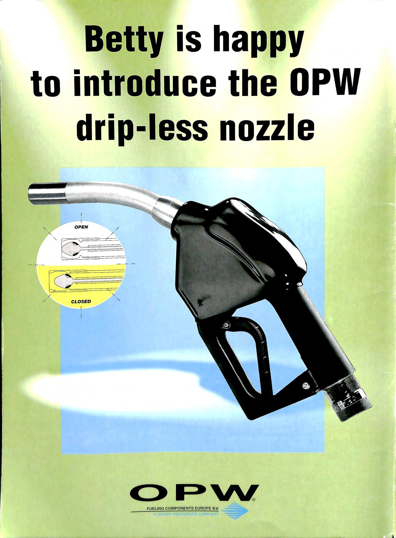
is happy to introduce the OPW drip-less nozzle I I '- OPEN / x / ' Q: · ' . x V/ CLOSED 'I I
Betty

ISO 9001 CERTIFIED
testing shows these products exceed EPA requirements for leak detection We
standards . ..
*Independent
don't just meet industry
a rage onsultancy ervices Ltd Cert . No FM 23290 Inspection Council for Eleclnca Installation Contract ng •ln E1111 APPROVED CONTRACTOR UNIT 10 MERTHYR TVDF PENTREBACH IL INDusri:u MERTHYR TYDFIL AL PAA!(_ MID GLAMORGAN CF4a 4DA TELEPHONE (Oi 4 FAX (01443) 6921 :;> ss2008 -----------FUEL TANK INSTALLATIONS APPROVED INSTALLERS OF STEEUUPP/APT PIPEVv FUEL MONITORING AND METERING EQUIPMENiORk: ERNEST IRELAND CONSTRUCTION SUB-CONTRACTOR OF THE YEAR 1995 1973 - 23 YEARS OF SERVICE TO THE PETROLEUM INDUSTRY --~----~~~~~~~~------~~~-~
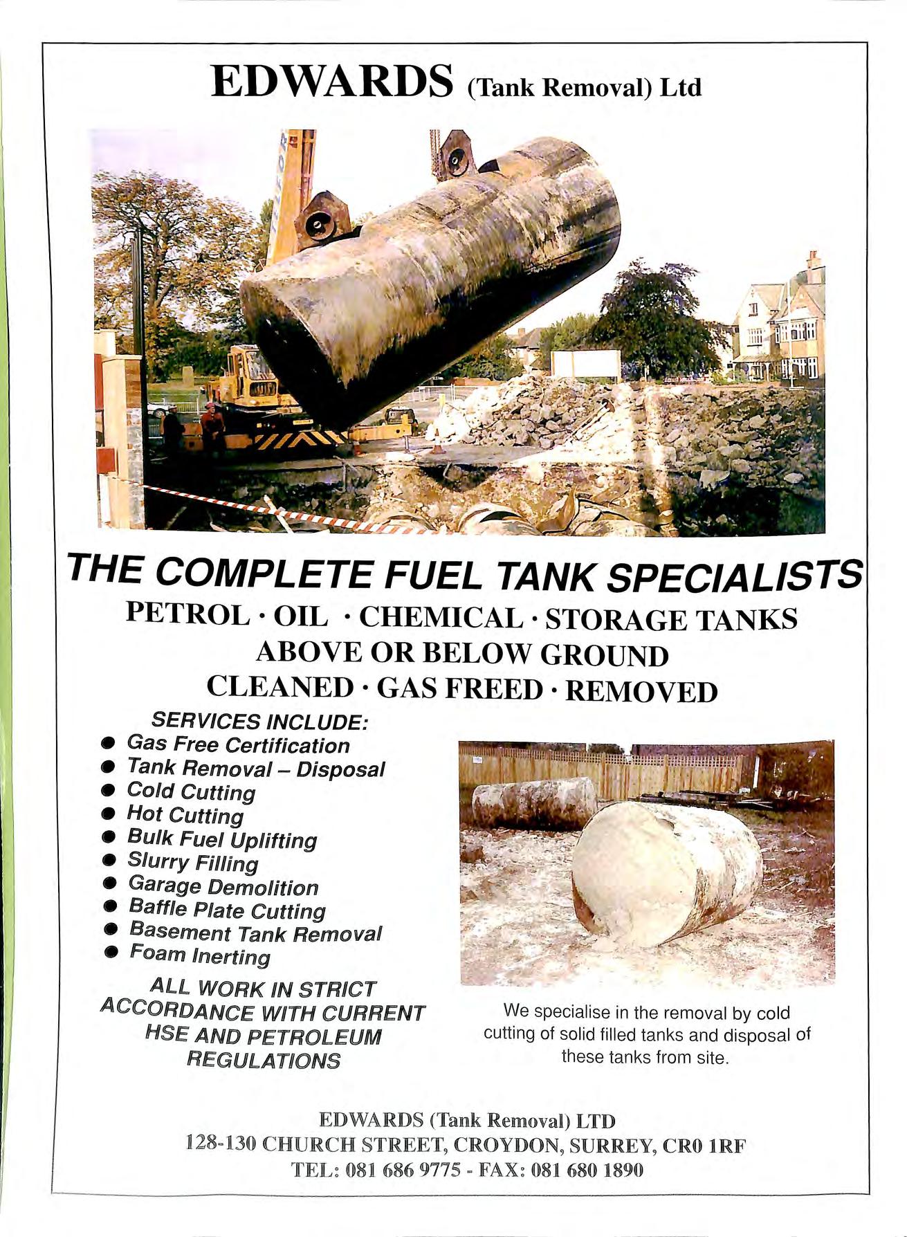
ED WARDS (Tank Removal) Ltd THE COMPLETE FUEL TANK SPECIALISTS PETROL · OIL · CHEMICAL · STORAGE TANKS ABOVE OR BELOW GROUND CLEANED·GASFREED·REMOVED SERVI C ES INCLUDE: • Ga s Free Certification • Tank Removal Disposal • Cold Cutting • H o t Cu tting • Bulk Fuel Upli ft ing • Slurry Filling • Garage Demoli t ion • Battle Plate Cutting • Basement Tank Removal • Foam lnerting ALL WORK IN STRICT ACCORDANCE WITH CURRENT HSE AND PETROLEUM REGULATIONS We specialise in the removal by cold cutting of solid filled ta nks and disposal of these tanks from site. EDWARD§ (Tank Removal) LTD J128 =13 0 CHURCH STREET, CROYDON 9 SURREY, CRO lRF 081 686 9775 081 680 1890

Sa ve time, Save money! ... Fit easy installation bulkhead seals BY TOTAL CONTAINMENT • Superior quality • Single hole installation • Suitable for all pipework systems • Suits all makes of containment chamber • Competitive prices PURFLEET FORECOURT SERVICES TOTAL = CONTAINMENT 520 London Road , West Thurrock, Grays, Essex RM20 3BE Tel: 01708 863931 Ext 219 Fax: 01708 864140 So le UK PU RFLEET FORECOURT SERVICES LTD Distributor LEDBURY WELDING & ENGINEERING LTD. (T EL : 01432-275566) NETHERWOOD ROAD, ROTHERWAS INDUSTRIAL ESTATE, HEREFORD HR2 6JU (FAX: 01432-358493) A COMPLETE RANGE OF ABOVE & BELOW GROUND STORAG E V ESS ELS QUALITY UNDERGROUND TANKS DOUBLE AND SINGLE SKIN QUALITY UNDERGROUND TANKS SPECIAUST COAT IN G LEAK DETECTION OVERFILL PREVENTION DEVICES MANWAY ACCESS FRAMES _ MULTIPLE COMPARTMENTS ABOVE GROUND 9 FULLY BLINDED TOTALLY ENCLOS E D 6 DERV=PAC KS 9 600 GALLON TO GAllON °

PETR VEND SITE SENTINEL TANK GAUGES Expandable, Modular Environmental Monitoring System for up to 128 Probes or Sensors ! ! FIBRE OPTIC CAMERA I PUMP SYSTEM Cleans Live Petroleum & Chemical Tanks without removing Product, Lids or Customers THE HYDRO CARBON ABSORBENT.. .. that you can re-use again and again....... Up to 100 times! .... Huge Range+ Free Vidio OIL AND GREASE ELIMINATING PRODUCT Ideal for Tank & Forecourt Cleaning [ ENVIRONMENTALLY FRIENDLY] + Free Vidio Sub Distributors Wanted- Excellent Discounts. Great Technical Support Leif Dige UK Ltd 9 The Colonnade Woolston Southampton SOI 9 7QT Tel: 01703 444877 Fax: 01703 447791
TEL: 0181-850 2211 FAX: 0181-850 5599
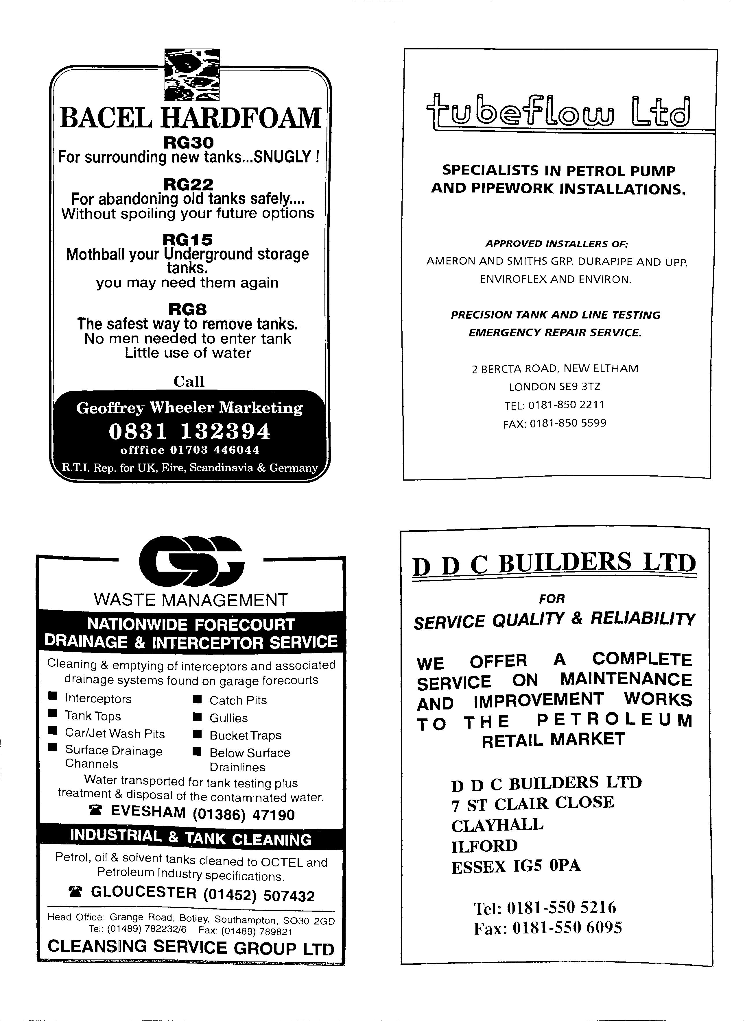
BACEL HARDFOAM RG30 For surrounding new tanks SNUGLY ! RG22 old tanks safely.... Without sparling your future options RG15 Mothball your Underground storage tanks. you may need them again RGB The safest way to remove tanks. No men needed to enter tank Little use of water Call Geoffrey Wheeler Marketing 0831 132394 offfice 01703 446044 RT.I. Rep. for UK, Eire, Scandinavia & Germany WASTE MANAGEMENT NATIONWIDE FORECOURT DRAINAGE & INTERCEPTOR SERVICE Cleaning & emptying of interceptors and associated drainage systems found on garage forecourts • Interceptors • Catch Pits • Tank Tops • Gullies • Car/Jet Wash Pits • BucketTraps • Surface Drainage • Below Surface Channels Drain lines Water transported for tank testing plus treatment & disposal of the contaminated water. a EVESHAM (01386) 47190 INDUSTRIAL & TANK CLEANING Petrol, oil & solvent tanks cleaned to OCTEL and Petroleum Industry specifications. V GLOUCESTER (01452) 5 07432 Head Office: Grange Road, Batley, Southampton 8030 2 GD Tel: (01489) 782232/6 Fax: (01489 ) 789921 CLEANSING SERVICE GROUP LTD SPECIALISTS IN PETROL PUMP AND PIPEWORK INSTALLATIONS.
INSTALLERS OF: AMERON AND SMITHS GRP. DURAPIPE AND UPP. ENVIROFLEX AND ENVIRON. PRECISION TANK AND LINE TESTING EMERGENCY REPAIR SERVICE.
APPROVED
2 BERCTA ROAD, NEW ELTHAM LONDON SE9 3TZ
D D C BUILDERS LTD FOR SERVICE QUALITY & RELIABILITY WE OFFER A COMPLETE SERVICE ON MAINTENANCE AND IMPROVEMENT WORKS TO THE PETROLEUM RETAIL MARKET D D C BUILDERS LTD 7 ST CLAIR CLOSE CLAYHALL ILFORD ESSEX IGS OPA Tel: 0181-550 5216 Fax: 0181-550 6095
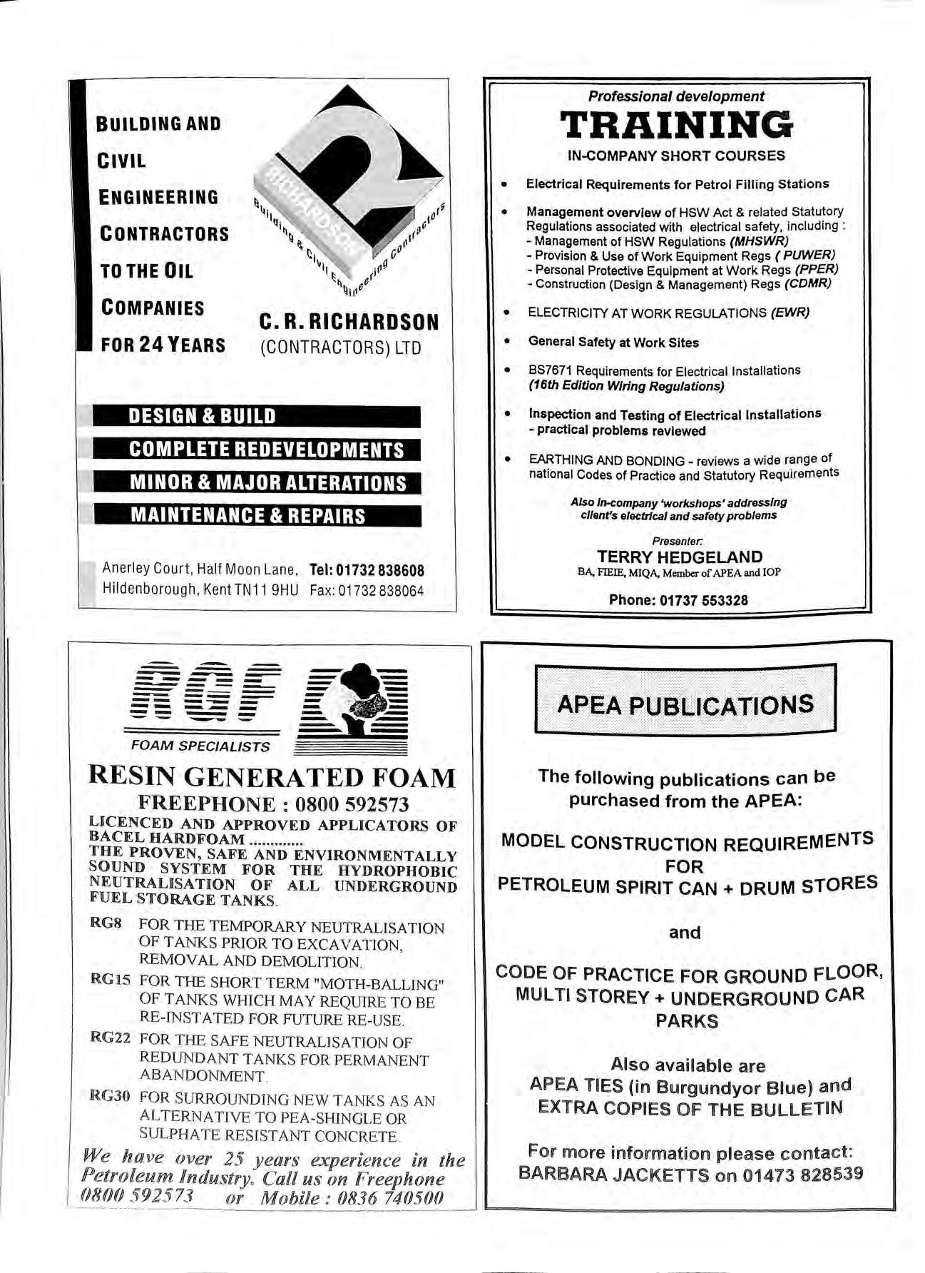
BUILDING AND CIVIL ENGINEERING CONTRACTORS TO THE OIL COMPANIES FOR 24 YEARS C.R. RICHARDSON (CONTRACTORS) LTD DESIGN & BUILD COMPLETE REDEVELOPMENTS • 1'1II:t1 J; I :J J;1:1 § i ;f:i j I1J: tW MAINTENANCE & REPAIRS Anerley Court, Half Moon Lane, Tel: 01732 838608 Hildenborough , KentTN11 9HU Fax: 01732 838064---------- ---- ---------------:-_-._ .=. .,li ..:: -. ..--FOAM SPECIALISTS RESIN GENERA TED FOAM FREEPHONE : 0800 592573 LICENCED AND APPROVED APPLICATORS OF BACEL HARDFOAM THE PROVEN, SAFE AND ENVIRONMENTALLY SOUND SYSTEM FOR THE HYDROPHOBIC NEUTRALISATION OF ALL UNDERGROUND FUEL STORAGE TANKS. RG8 FOR THE TEMPORARY NEUTRALISATION OF TANKS PRIOR TO EXCAVATION, REMOVAL AND DEMOLITION. RG15 FOR THE SHORT TERM "MOTH-BALLING" OF TANKS WHICH MAY REQUIRE TO BE RE INST ATED FOR FUTURE
We have over 25 years experien c e in the Petroleum Industry Call us on Freephone 080(} 5 92 5 73 or Mobile : ()836 74050() Professional development TRAINING IN-COMPANY
COURSES
Electrical Requirements for Petrol Filling Stations • Management overview of HSW Act & related Regulations associated with electrical safety, including : Management of HSW Regulations (MHSWR) Provision & Use of Work Equipment Regs ( PUWER) Personal Protective Equipment at Work Regs (PPER) Construction (Design & Management) Regs (CDMR) • ELECTRICITY AT WORK REGULATIONS (EWR)
General Safety at Work Sites
BS7671 Requirements for Electrical Installations (16th Edition Wiring Regulations) • Inspection and Testing of Electrical Installations practical problems reviewed • EARTHING AND BONDING reviews a wide range of national Codes of Practice and Statutory Requirements Also In-company 'workshops' addressing cl/ant's electrical and safety problems Presenter: TERRY HEDGELAND BA, FIEIE, MIQA, Member of APEA and IOP Phone: 01737 553328 The following publications can be purchased from the APEA: MODEL CONSTRUCTION REQUIREMENTS FOR PETROLEUM SPIRIT CAN + DRUM STORES and CODE OF PRACTICE FOR GROUND FLOOR, MULTI STOREY+ UNDERGROUND CAR PARKS Also available are APEA TIES (in Burgundyor Blue) and EXTRA COPIES OF THE BULLETIN For more informatnon please contact: BARBARA JACKETTS 001 01473 828539
RE-USE. RG22 FOR THE SAFE NEUTRALISATION OF REDUNDANT TANKS FOR PERMANENT ABANDON1\1ENT. RG30 FOR SURROUNDING NEWT ANKS AS AN ALTERNATIVE TO PEA-SHINGLE OR SUL PHATE RESIST ANT CON C RETE
SHORT
•
•
•
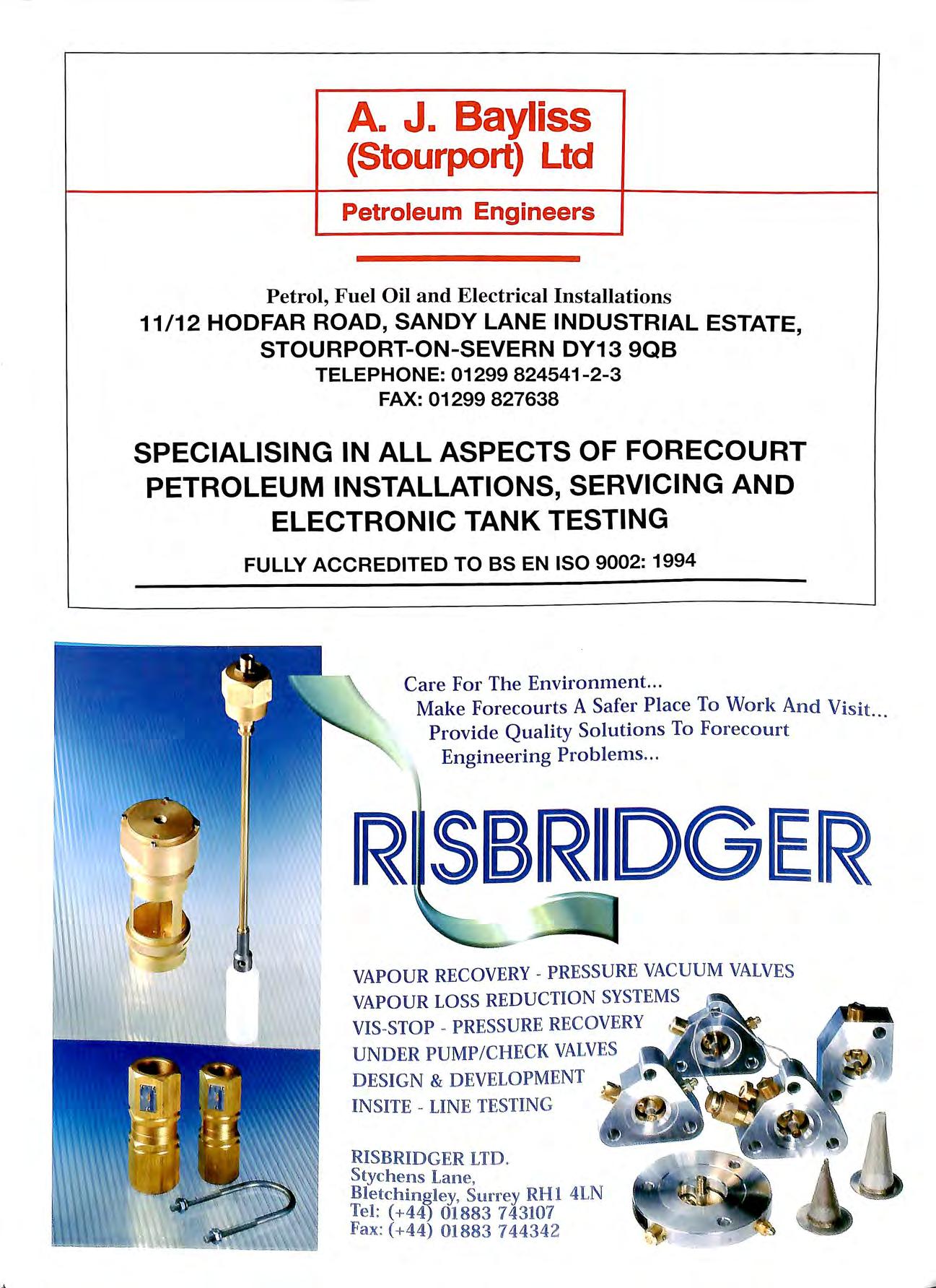
A. J. Bayliss (Stourport) Ltd Petroleum Engineers Petrol, Fuel Oil and Electrical Installations 11/12 HODFAR ROAD, SANDY LANE INDUSTRIAL ESTATE STOURPORT-ON-SEVERN DY13 9QB TELEPHONE: 01299 824541-2-3 FAX: 01299 827638 ' SPECIALISING IN ALL ASPECTS OF FORECOURT PETROLEUM INSTALLATIONS, SERVICING AND ELECTRONIC TANK TESTING FULLY ACCREDITED TO BS EN 150 9002: 1994 Care For The Environ111ent. .. Make Forecourts A Safer Place To Work And Visit Provide Quality Solutions To Forecourt Engineering Problems ... R SBRllDGlER VAPOUR RECOVERY PRESSURE VACUUM VALVES VAPOUR LOSS REDUCTION SYSTEMS VIS -S TOP - PRESSURE RECOVERY , UNDER PUMP / CHECK VALVES DESIGN & DEVELOPMENT INSITE LINE TESTIN G RISBRIDGER LTD Stychens .l ane , Bletch ing!ey, Su r rey RHl 4LN Tel: ( +44) 01883 7 43107 Fax : (+44) 01883 74434 2

INSTALLING NEW TANKS? USEBACEL HARD FOAM RG30 for backfilling tanks • Absorbs hydrocarbons • High rigidity and cohesion • Insulates tanks on 't slurry in a hurry - call now for a free estimate Square · Lonclon · EC4A 3DE · Tel 0171 58 3 2007 · Fax 9 171 583 2008 NASH Nas h & Partners ha ve been working in partn ership with the Retail Petro le um in dustry for almost thirty yea rs, planning and deve lop in g retail in sta ll ations from a s trai g htforward pump ch a n ge to Europe's largest filling statio n. Every s tep of the way, from feasibi lity s tudie s and surveying, project management a nd com mi ssio nin g, we take care of every detai l. Wh e ther a maj or o il co mpan y or an indi v idual d ea ler, Our cli e nts 1· are ass ur e d of th e Nas h commitment to qua 1ty and ad he re nce t BS o 5750, back e d b y up to -th e m in ute tec hn o logy, tnnovatio d 11 an ex pe rti se From a g re f I e n ie d s ite to a full y operat iona l in s ta ll at1on, Nas h & Partn e rs d e!'iver c re ati ve yet hi gh ly pr ac ti ca l so lu tion s + ARCHITECTS • SURVEYO RS + TOWN PL ANNERS • PROJECT MANAGER S + PROPERTY CONSULTANTS NAS H & PARTNERS LTD+ s · · tation Approach + Southgate+ Cluc h ester +
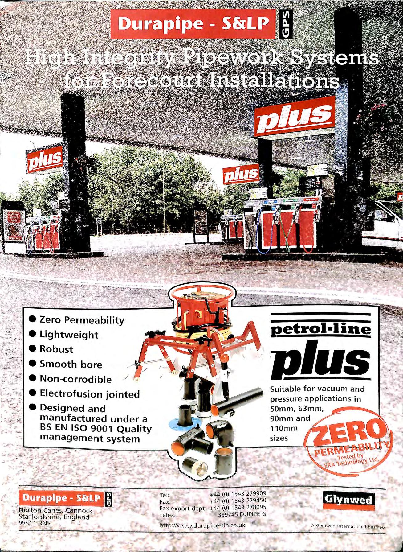
.. 'i ' •' ... ·"·,... +; ., •Zero Permeability •Lightweight •Robust • Smooth bore • Non-corrodible • Electrofusion jointed • Designed and manufactured under a BS EN ISO 9001 Quality management system .Fa x : Fax exp> €> rt C!lef§Jt: Tel e x : * 'Ftl41 1 +44 1543 .279 4 50 :1-44 (0) 154] 278095 DUF?IPE G eetrol·line Jl.fUs Suitable for vacuum and pressure applications in 50mm, 63mrn, 90mrnand L 110mm
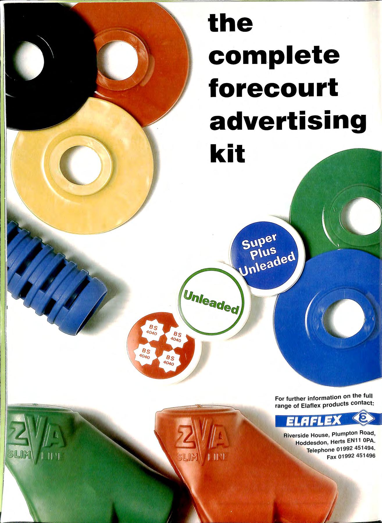
the complete forecourt advertising kit For further information on the full range of Elaflex products contact: fiiverside House , Plumpton Road , Hoddesdon , Herts EN11 OPA. Telephone 01992 451494. Fax 01992 451496

DAVID PLUMB & CC> LTD 169 Frenches Road, Redhill RH1 2HZ Telephone: 01737 767524 Service to the Petroleum Industry Since 1966 Member A.P.E.A. The safe alternative to water-filling of petrol tanks for certain applications Using our oil/water separator, we can dispose of water from petrol tanks at a fraction of the cost of tanker hire Work undertaken by fully trained and medically certificated personnel Hot and cold cutting, removal and documented disp osa l o f redundant oil and petro l t an k s . upl ift a n d tr ans f e r • Conve rti ng double=compartment tanks to s i ngle So li d f1llmg o f r edundan t t an k s • Cold cutt i ng open and disposing of solid-fi lled tanks Ex cavation • Tank removal • Con t am i nat ed soil disposal and reinstatement

D D

I CAMERON TECHNICAL SERVICES Specialist '°!f o'leco U 'lt e Oh t'lactof[,S Contract Maintenance 0 Up to 7 days/week O For all your forecourt and point of sale requirements 0 Accident & Emergency cover Comprehensive Installation Service .....----· REFURBISHED AND NEW EQUIPMENT REPAIRS & SPARES FOR ALL MAKES OF EQUIPMENT -, service exchange parts I next day delivery from extensive stock I simple payment terms 0 0 0 tel 01226 742441 fax 01226 747441
Talking Point
Proposals to amend the Petroleum (Consolidation) Act 1928 by the HSE and replace them by new regulations are well under way. The new regulations are at present being drafted and should be available for public comment during the summer.
What is important for our members on all sides of Industry is that the regulations are effective, fair and easily understood and should not allow a lesser standard of public safety. Although not on the original agenda presented to the Commission the HSE has decided that the new regulations would cover delivery of petrol to filling stations, a point made by Dr Rooker when he addressed our AGM.
This area of public safety is one the Executive needs to consider carefully, in recent years statistics show a drop in the number of delivery incidents, which is welcome news. This is almost certainly attributed to the training carried out by Industry and the result of strona and detailed legislation in this area. 0

While it is recognised that some amendments are needed to for a more flexible approach to driver controlled delivery, many on both sides of industry with years of experience are against wholesale tampering with effective legislation.
STEVE
of ROB GREEN ADVERTISING SU'RETARY
the Association
VOLUME35 Number2 MAY 1997
Bulletin Published by the Association for Petroleum and Explosives Administration
The
A company Limited by Guarantee registered in England No. 2261660 Administrator: Mrs Barbara Jacketts £8.00
Opinions expressed in this Journal are not necessarily the views (Free to Members) ISSN 0263 4597
Contents NOTES&NEWS AGM APEA TRAINING LETTER TO EDITOR TANK REMOVALS FLYING PUMP HOSES APEA BRANCH SECRETARIES 19 22 27 31 32 35 SIMON WHITE SOUTHERN BRANCH MIKE SILMON NORTH EAST BRANCH SUE MEADOWCROFT WALES BRANCH STUART CRISP EAST£RN BRANCH IAN HILLIER SCOTLAND BRANCH LINDSAY LLOYD MIDLANDS BRANCH
BLANCHARD HUMB£RSff)f: BRANCH HARRY REID NORTH WEST BRANCH NATHANIEL MCCOY IR£IAND BRANCH
We do not wish to return to the era of accidents like the Bi:istol explosion when 13 people were killed because of a misunderstanding during a deli very. THOMPSON EDITORIAL TEAM F/Jl10R 18
JAMIE
THOUSANDS OF GALLONS LEAKING FROM SMALL PETROL TANK CAUSES EXPLOSION IN WELSH HOMES
A leak of petrol from a tank at an Esso dealer site in Bontddu in North Wales last year was suspected as being the cause of an explosion in houses in April 1997, and resulted in the evacuation of a number of homes and a school close to the site.
The site is situated in a valley on the edge of the Snowdon National Park and the loss was discovered during August to September following complaints about petrol smells. Investigations revealed that a 15,000 litre (3300 gallon) tank was leaking and it was suspected that the dip stick had penetrated the tank bottom. An estimated 61,000 litres (13,500 gallons) had been lost during this short period!
The site is situated high in the valley and after the tank was removed an attempt was made to flush out the product by pumping water into the excavation. Petrol eventually found its way into the valley towards houses and a stream. At one point reports have been received of the river catching fire as officials were trying to see if the product was still dangerous.
The villagers state that they are living in fear as bungled attempts to clean up the area have made matters worse.
The attempts to alleviate the situation have so far been unsuccessful and reports of an explosion appeared on radio and TV on April I 7 followed by newspaper reports the following day. The reports came as contractors working for the Environment Agency were carrying out soil gas surveys and drilling close to houses.
During this operation the residents experienced an increase of petroleum vapour in the houses and as the local authority were called to investigate an explosion occmTed.
Mr Collet an occupier told of a small rumbling noise which grew louder. He ran outside and noticed the end of the house moving, the cupboard door under the stairs , blown off flames were seen 2ft off the floor and scorch was , marks were seen around the skirting boards and plasterboard panels were blown off the t The Soul·ce of ianition was thought to be the lire proper y. , e , from where flames were seen to turn blue JUSt belore the explosion. It was fortunate that no one was hurt. but as t_he Bulletin goes to press a public meeting has been held with the local MP and residents. and a number of awkward questions are being asked about the efforts of the various agencies dealing with this leak.
STAGE 2 VAPOUR
RECOVERY
PROPOSALS FOR THE UK
In what was a shock announcement on March 1O industry leaders were called to a meeting with the Minister for the Environment Earl Ferrers to break the news that in spite of the fact that there is at present no ao-reed timetable • b m Europe the UK government intends to introduce stao-e 2 Vapour Recovery. 0
A consultative document is expected to be published in the near future and although the thresholds and areas to be covered will be determined by consultation it ·will affect many service stations in built up areas and those with a hio-h b throughput. Industry sources were expressing dismay at the news, many had thought they had some years to prepare until the European Union had reached agreement on the timetable. The UK however are only following the action of close neighbours as Germany, Holland have already legislation in place.
SERVICE STATIONS CLOSE
The figures recently published showed that 1996 has been the worst year for service station owners in the UK. Many feel the largest number of service stations to close was as a direct result of the "price war", which shows no sign of abating. In 1996 a total of 1496 sites closed up shop and came out of the business, the largest drop in over Jo years. The survey carried out by the Institute of petroleum does not cover private refuelling installations where evidence of closure has also been high. There now remain 14,748 service stations in the UK of which 11600 are self service and 6405 of those are Oil company owned as a result of the closures the average throughput has risen per site to approx 2 million litres per year. Some industry sources are predicting that the number of sites to close will continue at this rate but settle at around 11000 stations.
TRAINING COURSES
The APEA are running a series of training courses 1997 /8 at excellent rates on all aspects of petrol hllm? statmn. details are available in a separate sheet which 1s ?emg _sent with the Bulletin. should you re4uire further 111lormat1011 or another form please contact Brian or Eileen Taylor on 01582 882170.

notes and news
J l)
APEAINTERNATIONALCONFERENCE AND EXHIBITION ON PETROL STATIONS
The APEA have organised a much larger event for the 1997 Conference and Exhibition at the NEC Metropole Hotel in Birmingham for the 10/11 November 1997.

The Conference will cover a number of subjects involved with the building of and running of petrol stations including some exciting new products that companies have chosen to launch at this years event.
Should you not have received information on the exhibition please contact Chris Knight on 01992 451494 or Barbara Jacketts on 01473 828539.
Further details will be sent to member, but please reserve these dates in your diaries.
NATIONAL ONE STOP REFUELLING SHOP
FORECOURT ENGINEERING have expanded their operation of refuelling site equipment supply and support to cover the whole of the UK.
Based in Farnborough, Hants, FORECOURT ENGINEERING offer a "one stop solution" to companies looking for pipe-work, tanks, pumps, fuel management systems, or service to their existing equipment. The company has gained a reputation for professionalism which has spread further than its traditional heartland of Southern England. So much so, that a conscious decision had to be taken about how far the company's supply area should to. Tony Jenner, Forecourt Engineering's Managing Director explains:
"Traditionally most companies operating fuelling sites, use a supply and support company close to their depot. The arises when there is more than one site. Issues can ecome quite complicated when vou have to co-ordinate several ··up 1· · d"-FF. · " P ters Ill (uerent areas."
By ff · · enng national coverage, the company believe that they w11l appeal to site operators who wish to make only one pho_ne call to have their problems solved. According to D1rector Barry Jenner, the company had little choice: Although we have been considering this expansion for some time "t II · t was rea y our customers that convinced us that the tim, . I M t was rtg 11. any our larf?er clients operate thmuf?hout tl UK u1 ze vve are pleased that thev are so confident in · / ·1· d · · · ow a 'Jt 1ty to o the 1ob, thev have requested that w,, \'UJJfJ •1 1. 1 · c • 01 t ze1r sites."
With single partnership arrangements happening more and throughout industry. perhaps we will see a lxoltlerat1·n cit· " 1 t h I · " · ·1 01 e s op s ops so ut1ons s11rn ar to that offered hy Forecourt Engineering.
NEW OVERFILL PREVENTION
DEVICE
In June 1997 Risbridger plan to release an all new design of overfill prevention device (O.P.D.) named RIS-STOP. Based on extensive investigation into existing designs and future European site requirements for this type of product, Risbridger have developed a unique valve that overcomes the performance limitations of most existing designs at a competitive price level.
By external separation of the level sensor and shut-off valve sections of the device, it is possible to provide operational testing via an integral test valve. This represents an important advantage over drop tube mounted designs allowing routine performance checks to be made whilst the tank is being filled during normal operation. Overfill and resetting failure rates with existing non-testing designs in our opinion is unacceptably high, and merely removing the valve from the tank and visually inspecting it cannot guarantee it is in working order.
Another advantage of the RIS-STOP layout is the very low pressure drop gained by mounting the sensor and shutoff valve actuator outside the drop tube flow path. This results in faster tanker drop times.
Careful attention has also been given to ease of installation, which is normally a major cost factor. By designing the valve to fit directly into an existing 4" tee, offset fill units can be installed by merely replacing the existing plug and drop tube cage with the RIS-STOP cartridge. The standard drop tube does not require modification. The sensor cartridge is similarly designed to be installed directly into any auxiliary 2" fitting. If a spare lid port is not available a special vent port adaptor will be supplied.
The majority of UK sites will require no modification to existing pipework to install a RIS-STOP. The connection between the sensor and valve cartridges is made with a petrol resistant hose assembly.
The proposed CEN standard for this category of valve can be met in all aspects by the RIS-STOP design which clearly addresses many problems outside the scope of this standard.
A direct fill version of the RIS-STOP is also under development offering similar advantages. At this time Risbridger is testing this product at selected sites to establish the optimum sensitivity, pressure and flow calibrations for the unit.
For further information please call Annie Risbridger or visit us at the Forecourt Show in June.
20
BARRY GOLDSMITH Engineer BP Oil Europe
An appreciation
It was with the most profound shock and intense sadness that I learned of the untimely death of Barry Goldsmith earlier this year. He was just 49 years of age and in the prime of his life.
Barry will be remembered by many in the retail petroleum industry here in the UK as an engineer with BP and latterly in Europe where he worked in their European headquarters. I knew him for over 17 years, having taken him on as a young engineer for BP in 1979. There was something instantly compelling about him even then and I well remember my boss's comment "he'll be trouble" on his candidature at interview, but said with that twinkle in the eye which was an affirmation of the choice!
Barry would never accept anything at face value or just because it had always been done that way without challenge. He always sought to on the existing and strove for perfection, upsetting some i'n the process whose offering was less than adequate, but he would never ask anyone to do anything he was not prepared to do himself. Never one to suffer fools gladly, he nevertheless respected wisdom, logic and genuine debate in the search for a better solution or a clearer understanding. Seen by some as the 'enfant terrible' of retail engineering he was, in truth a sound, competent, thinking and pragmatic practitioner with more than a touch of healthy scepticism which made him a good engineer rather than a high flying intellectual or an unthinking follower of the latest fad or fashion.
But it really was as a person that many of us with whom he came into contact will remember him. His personal qualities were complex but essentially compassionate. Barry was a very caring person who with a soft heart beneath an outwardly tough shell. He cared deeply about people, although he did his best to conceal it from those for whom he had no time! He held deeply and genuinely felt concerns for those who he respected and for those he considered had been treated less than fairly. He was a great communicator, believing in the importance of building relationships and maintaining contact with people after they moved on from his immediate sphere of activity. It is a measure of this quality that only last year he went to great lengths to arrange and attend a reunion in Stratford upon Avon for all those enoineerino and other retired BP staff b b with whom he had been associated during his career.
Since his early days in the industry, Barry was a supporter of the Association and was Chairman of its Eastei:n Branch whilst in the UK. Keen to help with the establishment of a Euro B h f II h. pean ranc o owmg 1s move to Brussels he beoan mak 111g t .1 1 ' . o con acts unt1 a JO, move away trom retail and then a tr· I b · · · I ')C'4 . 1p e ypass operation 111 ' 1 conspired to prevent this being followed through.

It is difficult to believe that we shall never again see those craggy good looks with the piercing blue eyes or hear those pithy comments. The industry has lot a person of great character and considerable potential as far too early an and I have lost a good friend as well as a colleague. The lives all who knew him were enriched by the experience will now be poorer for his departure. He will be sadly missed by all. To his two daughters Rachael and Becky and Gabnela we extend our deepest sympathies at this sad time.
Michael Lugg COLIN JONES
Jones a of the Association and past Chairn.rnn of the tragically died recently followmg a road accident. Cohn was badly injured when the coach he was driving crashed in Coventry two weeks previously. Colin a former Fire Officer was responsible for training in the West Midlands Brigade colleagues said that he would be greatly missed and gave ll0% to the fire service. He was instrumental in updating first aid trainin o for 3500 fire-fighters before becoming involved in fa: safety work as the petroleum officer. In addition to his work on the Association Colin was Chairman of Ryton Parish Council and secretary of the Coventry and Solihull Fire Protection Association. The Association extends sympathy to his wife and family.
Christopher James Savill, an electrician trading as L.W. Savill & Son from Witney, Oxfordshire, pleaded guilty at Cheltenham Magistrates Court on the 7th January 1997, to supplying a forged petroleum filling station electrical certificate to BoUJton Vale Garage in October I 99S contrary to the Health and Safety at Work (etc) Act 1974: These electrical certificates help prove the site is safe for the public to use. Mr Savill was found to have altered a photocopy of another certificate. Gloucestershire's tradino standards staff, however. discovered that the document wa: false, and as a result Savill was prosecuted and fined £30() with £400.
Paul Galland, County Trading Standards Officer says: "This i.1· an 111111s11a/ hut important investigation as it relates to safe(\' checks at a petrol station. \\'here rclwnce is fJUf 011 the and (J( the conipleting these cerflf1rntes. A sat1.1facton· cert1f1cute indicwcs the e/ectrirn/ on a site is safe and 11·i// not present any /w::.ard to stlCft or.111e1nher.1'_of the puh/ic using a sen•ice station. Pl'fm/eum sp1nt 1s a /ugh/.\· dangerous product and hreaches of anr /1ce11ce co11d1t1011 or !euis/uti 1111 1·,. · . . - •• ,.., \'IC\\'ed 1·en· senouslv hv the department.
21
PETROLEUM LICENSING ELECTRICAL CONTRACTOR FINED £700 FOR FORGED CERTIFICATE
AGM
 Phil Mon ge r h d. an zn g chair to B Th arry ompson /),- Rook f:' r H S Efi e ldin g c1u es tion.y on New L eg i s la tion changes
The following officers and council members were elected at the AGM at Markyate on 14 April to serve for the 1997/8 period.
Officers Chairman Vice Chairman Secretary Treasurer Editor Advertising Sec
Barry Thompson John Boudry Andy Berry Tom Wigfull Jamie Thompson Robin Green
Phil Mon ge r h d. an zn g chair to B Th arry ompson /),- Rook f:' r H S Efi e ldin g c1u es tion.y on New L eg i s la tion changes
The following officers and council members were elected at the AGM at Markyate on 14 April to serve for the 1997/8 period.
Officers Chairman Vice Chairman Secretary Treasurer Editor Advertising Sec
Barry Thompson John Boudry Andy Berry Tom Wigfull Jamie Thompson Robin Green
_J
Council Members Gordon Kinnear Chris Knight Mike Lugg Jack Samson
o
')' __
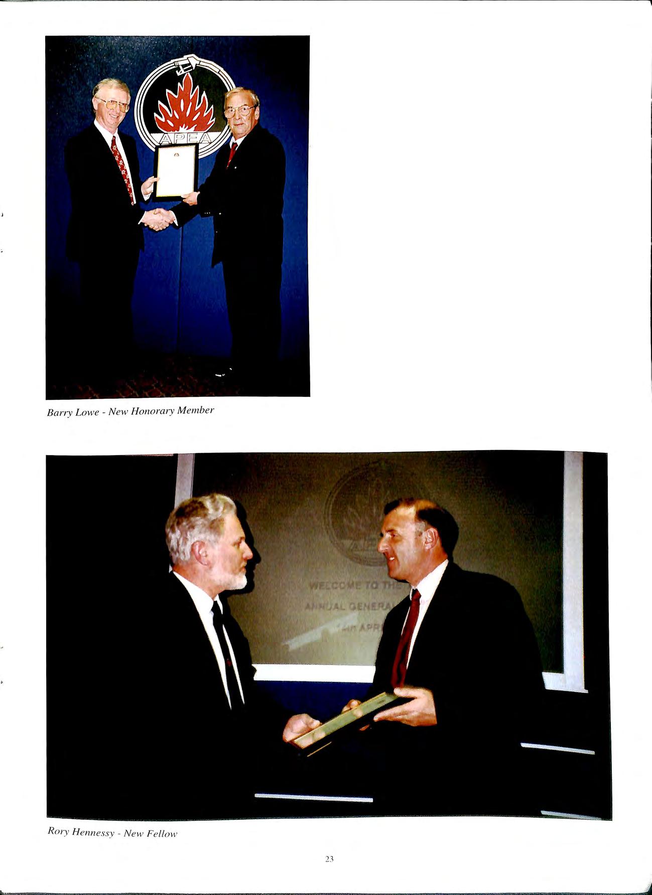
Barry Lowe N e w Honorary Member
R
ry H e n nessy New Fe ll ow
GUARANTEED BIOREMEDIATION SERVICE LAUNCHED
Leading bioremediation technology provider Response Environmental Services has launched an effluent treatment service which for the first time guarantees both performance effectiveness and cost savings for industry. The Bioflow Effluent Treatment System (BETS) has been developed by Response Bioflow, a division newly formed to champion the development and delivery of bioremediation solutions for the processing of trade effluent and other liquid waste.
At the core of BETS is Novacell™, a unique, in-situ automatic dosing system which carefully breeds and releases into the effluent stream microbes that are preconditioned according to the nature of the waste, to continually treat the contamination efficiently and effectively.
BETS comes with a distinctive double guarantee
In the first instance Response Bioflow will assess the pollution to be tackled and will only recommend that Novacell™ be installed either as a stand-alone system or as an enhancement to current treatment plant if it is proven that the user will save money. Savings typically come from two sources: lower payments to water companies for treatment of effluent discharge and the removal of lowering of payments for collection and disposal of industrial wastes.
Sec?ndly, the company promises that once the system is operatmg an • · optimum equilibrium' normally 3-6 weeks followmg install t" · ·11 · a ion then effluent quality w1 improve by at least 30% within the first 6 months of installation.
BETS is extr 1 · · · · b h . eme y versatile and 1s effective m ot contmuous flow d 1 an closed-loop applications either as an exc treatment system or in addition to existing OAF, aeration filtrati ' on, activated sludge or other systems.
This k mar et leading combination of advanced microprocessor 1 b ·t contra led hardware and high performance ac ena, Is provided h. 1 W1t m a service arrangement which, e 1mmates the d · nee for Capital Expenditure. These arrangements includ serv· h. e a range of support and advisory . ices w ich comb· users. me to maximise the benefit of BETS to
A range of sup maxim·. h port and advisory services that combine to ise t e benefit of BETS to users.
As pa11 of th . . e service, BETS users will also be offered an option whi ·h 1 . Up .. d . c a lows them to automatically receive gia es 1n equ·1Pment or advancements in biotechnology
engineering as they are developed. This has the advantage of providing its customers with a capability to face future legislative pressures and to tackle attendant cost increases with more confidence.
Contact Shelly Cockayne Tel. 01709 816104.
INNOVATIVE CLEAN AIR BLANKET
Prestige Air-Technology, the UK's leading innovator in the treatment of soil gas emissions, has developed a Clean Air Blanket for sites which are contaminated.
The Clean Air Blanket
The Clean Air Blanket is a fully integrated system, specifically designed to protect buildings from the of hazardous gases. Patented and with full efficacy insurance it is the only comprehensive product on the market for the safe protection of both existing and new build sites.
Unlike passive venting systems, the Clean Air Blanket provided continuous protection against soil gas ingress the system incorporates telemetry to further ensure this level of protection. It is the only integrated, one-stop system that has been proven to be 100% effective.
The Membrane Integrity Test , Also being demonstrated is Prestige Air-Technology s Membrane Integrity Test, designed to ensure that _gas membranes, once installed, are fully effective agamst further gas ingress. The test, which is carried out on the membrane immediately after installation and prior to the ensuing construction processes, ensures certification all leaks have been sealed. The Membrane Integrity Test is unique within the industry and can be used to test any gas membrane including the Clean Air Blanket.
Commenting on the Prestige Air-Technology systems, Malcolm Martin, director said:
"The recognition and reputation of the Clean Air Blanket and the Membrane Integrity Test is based on the number of problem sites, ranging from landfill sites to petroleum service stations, which we have been able to resolve successfully over the years since we introduced the two systems. In each case no other contractor h ad been able to find a solution, whereas the Clean Air Blanket, once installed, proved to be completely effective. I believe that our success in these problem sites, and the many other projects we have undertaken since, stand as the very best endorsement of our systems."

24
CLEAN AIR BLANKET
The Death of the Petrol Station
One reader sent me a photograph demonstrating how the death of the petrol station turned into reality as this old filling station was taken over by a Funeral Directors. The old canopy is very useful for keeping the coffin dry, the shop turned into a chapel of rest and the pump island has been fashioned into a tasteful flower bed!

,
A:ln CLEAN AIR BLANKET I
NEW GASKET MATERIAL
Hytek Ltd has introduced a new line flex gasket material for use in the petroleum industry and after some extensive testing is proving to be an adequate solution to the industry needs.
The material make up is confidential but is a flexible plastic material which is resistant to petroleum products.
Test Performed
1) A sample of each gasket was located in a simulated pipe-line situation using the corresponding flexible connector and mating flange. The flange bolts were tightened with a torque wrench to 33Nm.

The gaskets were subjected to an internal pressure of 4.0 Bar, in both open and closed positions.
Results:
No indication of the gaskets leaking could be detected.
Limited distortion took place but on relieving the pressure , the gaskets recovered their shape within a matter
of seconds without any detrimental affect to the material. The maximum level of distortion achieved did not hinder the use of the gasket when sliding them from one operational position to the other.
2) Samples of each of the gaskets were submerged in each of the currently available grades of petrol and diesel for long periods. This is an ongoing test and of course we will continue to monitor it on a week to week basis.
The same test was carried out within concentrated vapour environments of the above liquids rather than submerged in the liquid itself.
Results:
The gasket material suffered no degradation or chemical attack and the performance of the gaskets was in no way affected by the contact with petrol or diesel or their respective vapours.
Operational Parameters
The gaskets will not distort, crack or melt when subjected to temperatures across a range of -30°C to +80°C. They will suffer no loss of performance when used within this temperature range.
26
Letters to the Editor
Dear Sir
I always enjoy receiving and reading the Bulletin and Memory Lane in the last issue I can answer. I started work in the Wei crhts and Measures office in Crewe in 1932 and I b do recall the pump in question. I placed the date in my mind between 1932 and 1935. I contacted an old colleague in the Shropshire Trading Standards Department who kindly looked up the old Board of Trade notices between that period and confirmed it to be May 1934.
 Bob Holdaway Shrewsbury
Editors Note
Not bad for the Ex Editor now over 80! Some of us cannot remember what happened last week!
The
MEMORY LANE
What year was this one built?
Dear Editor
Re: Memory Lane
The petrol pump featured in Volume 35 of the Bulletin was submitted to the Board of Trade Standards Department, Chapter Street, London in 1946 to ascertain whether the pattern was not such as to 'facilitate the perpetration of fraud'. It was submitted by Broadway Equipment Ltd of Bracknell Gardens, London and received a certificate number 900 on the 27 May 1946.
Yours sincerely D James Principal Officer
hand operated one was approved in 1934 and the electric one in 1946.
3 1
Tank Removals ... Foam or Water?
By John Cole
TANK REMOVALS ... FOAM OR WATER?
Over recent years many of the established practices have been re-evaluated in the Jiaht of a aeneral consciousness of b b e nvironmental and perso nnel safety. None more than the ever-present requirement for the safe removal of redundant und erg round fuel storage tank s
Although all Licen s ing Authorities may vary in their approach to thi s operation, the collective aim has been to follow a p - t' h rac ice t at gives the highest attention to protect mg the · _ e n v u o nment coupled with the m ax imum sa fety of the pe 1·s I onne carrymg out the operatio n.
Over the la st d d eca e, the most favoured method for safe tank removal s 1 • b las ee n the use o f water for in serting the tctnks pnor to a d d .· . n u1 m g th e tank excavat ion In m any ways thi s method h · d a g reat advantages over tho se in oeneral practice ove tl . 0 1 l e preceedmg yea rs Only too well, I 1e m e mber rem ·
. ov mg underground fuel sto raoe tank s m the late s ixties a nd ea 1·l y b · ' seve nti es with only a minimum regard lo th e dano e rs t 1 . . b • o t l ose perso ns m vo lved 111 the operatio n a nd ev en less d . . . · · un erstand 1n g of the possib le det re m e nt aJ e fl ec ts t tl l · · 0 l e oca l e nvironment.
In brief, the generally accepted g uid elines for tank removals using water are to:-
01) Drain back the su cti ons to the tank and purge the lines with air, water or nitrogen
02) Remove bottoms from tank using manual or hydraulic equipment from outside the tank
03) Seal contamjnants and remove from site to a Registered site of di sposal.
04) Transport water to site and fill tank to capacity venting through the exi sting vent.
05) Excavate over and around the tank, taLing care not to puncture the tank and release any contaminated water.
06) When the tank is ready to be removed, reduce the level of water in the tank by abo ut 300mm and dispo se as 03) above.
07) Cold-cut a n opening in th e top of the tank to a ll ow easy access and water removal.
08) Up-lift the remainin g water into a tanker and remove from site to site of origin and obtain certification.

09) Ventilate tank with compressed air us ing e quipm e nt that is earthed and with air-line that is non-condu c tive.
I
0) When atmosphere is below I 0 % LEL a Gas Free Certificate is iss ued to allow the tank to be re moved.
11) A Speciali s t Operator may now e nter th e tank with full brea thin g apparatus and remove any remaining co ntamin ants.
N o w that th e use of Bace l Harclfoam has become a n <Jc n : p! e d m e thod of t·i k · · k · ' 11-.,e lnr ;i ll (1nJ...
c n 1n se rt1on we ca n now loo at its la nk re 111 ova l . lei · 1 h · c11 exa min e any ac vantages t at 1t
12) Th e tank to be re- ve ntilated until a read in g of below 10% LEL is co nstant.
l 3) The tank may then be removed from the exc avation and co ld c ut fo r di s posa l from s ite.
DISADVANTAGES
1)
ACCESS REQUIRED INSIDE TANK ... In order to remove all contaminants, it is necessary to enter the tank with breathing apparatus. This is a hazardous operation and requires specialist equipment and two specialist operators.
ACCESS REQUIRED INTO TANK EXCAVATION
In order to cold-cut the opening in the tank top, it is necessary to enter the excavation and for the operative to stand on top of the tank to carry out the works. This is a hazardous operation as there is the possibility of the operative sliding between the free-standing tank and the sides of the excavation which will be to approximately 3mts and unsupported.
FREE-VENTING OF TANK When the tank is being vented, prior to access and removal, the vapours are forced into the atmosphere and the excavation from the tank-top opening and not controlled through the tank vent.
CONTAMINATION DURING EXCAVATIONS
Should the tank be punctured during the excavation works, the contaminated effluent will escape into the excavation and contaminate the surrounding spoil. This spoil will require removal, storage and transportation to a registered disposal site.
BULK MOVEMENT OF CONTAMINANT As all the contaminated final effluent has to be returned to the suppliers sewage treatment facility, this involves the transportation of large quantities of contaminated waste for which the Client will be responsible regarding both safety and audit trail documentation.
EXTENDED TIMESCALE Should the tank be punctured during excavation, the works will be halted whilst the puncture is repaired, the water topped up and the contaminated spoil within the excavation removed.
7) EXTENDED SPECIALIST ATTENDANCE As each tank is fully excavated, the civil contractor will be required to arrange for the specialist contractor to attend site to carry out the cold-cutting of the tank for the removal of the contaminated effluent by tanker. The civil contractor has then to ensure that the tank is removed from the excavation and the specialist contractor is in attendance to demolish the tank within the 24 hours duration of the Gas Free Certificate.
8) DIFFICULTY IN OBTAINING WATER In many areas of the United Kingdom, there are considerable difficulties in obtaining water and/or final effluent. Contracts in some areas will require transportation of water from another area. This will incur further costs as each tanker will be restricted in the number of loads to site in each working day.

Drain back the suctions to the tank and fit valves at risers at pump island positions.
Remove bottoms from tank using manual or hydraulic equipment from outside the tank.
Seal contaminants and remove from site to a Registered site of disposal. out tank using a water based biological cleaning flmd to remove the bulk of any remaining contaminants.
Inject RG8 foam into all suction lines from tank to valves at pump islands and cap off.
Disconnect the vent-pipe within the tank chamber and install a temporary vent to 3mts with flame arrestor fitted.
Inject RG8 foam into the tank via the direct or off-set fill pipe until foam is forced through the vent. The vent then capped off and injection to continue to pressurise the tank prior to capping off.
The tank may now be excavated and removed to a safe area or removed from the site for demolition. The tank may then be cold-cut in a horizontal plain with the inspection chamber uppermost, and the top section removed.
Any hydrocarbon contaminant, which is no longer flammable, which is absorbed into the foam, may now be pared off, sealed and removed from site to a Registered disposal site.
The clean foam may then be removed from site as a non-contaminated product. The current method being loading into a compaction vehicle and disposal to a registered land-fill facility.
The open lower section of the tank may then be entered if required, to remove any solid waste.
In brief, the generally accepted guidelines for tank removals using FOAM are to:01) 02) 03) 04) 05) 06) 07) 08) 09) 10) 11) 12) 13)
The remaining tank sections may then be remove from site for disposal.
ADVANTAGES
1) NO REQUIREMENT TO ENTER THE TANK As the tank is removed from the excavation completely inerted with foam, the cold-cutting is caITied out at a safe area on the smface. The tank is opened into two horizontal halves and the "de-sludging" is caiTied out within the open vessel.
2) TANK IS SAFE FOR EXCAVATION As the tank is completely inerted with foam, the excavation and removal of the tank is undertaken with the maximum of safety throughout.
3) ENVIRONMENTAL SAFETY Even if the tank is punctured, there would be no escape of contaminants. The foam will have absorbed the hydrocarbons and any liquids escaping would only be componants of the foam.
4)
NO BULK MOVEMENT OF CONTAMINANTS
As the foam absorbs the hydrocarbons from within the tank. it changes colour and is pared off and stored into sealed containers. The movement of contaminated waste is confined to the bottoms from the tank and the foam parings only.
2) 3) 4) 5) 6)
5) REDUCED TIMESCALE Following the injection of the foam, the tanks may be excavated, removed from the excavation and stored on site for demolition. In the case of empty tanks that had previously been water-filled, there is a maximum period of 24 hours before the vessels require to be re-tested to provide a further 24 hour cover.
6) REDUCED SPECIALIST ATTENDANCE The bottoming and foaming operation is carried out in one attendance over one day. There is no requirement to return to cold-cut until after the tank has been removed from the excavation. This allows the civil contractor to plan the contract without taking into account that the specialist contractor must attend the site following the excavation but prior to the tank removal.
Having undertaken many tank removal contracts using both water and RG8 Foam, and having conducted monitored experiments using foam both with injection techniques and demolition systems perhaps the time is right to seriously consider the implications of safe tank removals, more especially in the li ght of present day awareness of environmental conservation and personnel safety.

In less hazardous industries, the "old ways" are very often the chosen route, but should we not, in the everchanging climate within the petroleum industry, be evaluating "new ways" in an effort to keep the industry ahead of legislation and public opinion?
John Cole M.lnst.Pet. John Cole Surveying Agency Ltd APEA Member South Wales
FLYING HOSES ON PETROL PUMPS
Recent testing has been taking place following the fitting of break couplings on petrol pump hoses at the nozzle end, and the possible danger to petrol station users following a break and the resulting back lash. The APEA extended the
invitation to Mr Jack Gall Thomson an expert in break couplings to publish his report and give a demonstration at the recent AGM and members were quite surprised at the results.

TESTING OF JACK GALL THOMSON'S CABLE RELEASE COUPLINGS ON KERBSIDE PETROL PUMP HOSES
Tests were carried out over a period of weeks during November and December, 1996 and January, 1997 at the premises of Thomson Tek Ltd, 284 Rutland Road , West Bridgford, Nottingham.
In order to appreciate the work which wa s undertaken on thi s exercise , a few thoughts on the release coupling as opposed to the breakaway coupling should be explored.
BREAKAWAY COUPLINGS are intended to be activated solely by a linear overload of the hose. They may be parted by the shearing of rivets , ten s ional fra ct ure of pin s or studs , compression or expan s ion of circlips, or breaking of nec ked clown conduits. a ll are te c hnically diffe re nt , and all are preset to paiiing within hi gh and low hose overload figure s usually determined by leg islation. In the UK these figures are currently set at a low of 800 N ew ton s, and a high of 1,200 Newtons.
RELEASE COUPLINGS are, as the name implies , allowed to come apait by the application of an outside source of energy such as compressed air, hydraulic power or mechanical means. A very important asset for a release coupling is the ability to withstand very high linear and tangential overloads in the day to clay operational requirements , and do not come apait until commanded to do so by the application of the outside source of energy.
The outside source of energy applied in th e tes ts described here will be refeITed to as LINEAR DIFFERENTIAL ENERGY, and thi s is achieved as follows
The hose has a ste e l cable passing through its e ntire length and th e y hav e a common point of anchor at one e ncl The ca bl e is longe r than the ho se and is allowed to hav e it s extra length abso rb ed in sid e th e ho se. At th e op pos ite e nd to the co mmon ai1chor, th e ho se is fitted with a re lease co upling be tween itse lf and th e no zz le. and the ca bl e is attached to a moveabl e release m ec hani s m insid e th e coupling. Wh e n the hose is s ubj ec ted to a st re tching lo ad the movement of the co uplin g and no zz le is unhind e re d
35
until the slack of the cable is taken up. Any further energy applied to stretch the hose will apply an equal energy in reverse along the cable, and this will be applied to the release mechanism in the coupling. This is differential energy being applied in a linear fashion.
It follows then, that the amount of loose cable within the hose has a very marked influence on the timing of the coupling release in relation to the stretch of the hose. The physical method of controlling this surplus cable will be covered in a later chapter of this report.
THE TEST APPARATUS in use, consists of a nine foot air cylinder of three inch nominal bore operating directly on to a trolley running along a twin rail track, and the whole thing stretches in a horizontal plane to some twenty foot span.
A six foot six inch pillar forms a common anchor at one end for the cylinder and both high and low levels for the hose, a central platform is a control point for setting the various break points as well as housing the recording instruments, and the tail of the track rests on a buffered post, suitably balasted.
The trolley is designed to accept standard pump nozzles in current use, and is also fitted with a trigger release mechanism to which the hose can be attached and permits automatic release at repeatable stretch loads. This can be adjusted to suit different types and lengths of hose.
The cylinder is active for two thirds of its stroke, at which point vent holes are drilled. The remaining third is non active and the reverse side of the piston acts against the closed end to form a cushioning brake to the stroke.
Water inlet facility is provided for keeping the interior of the hose at a pressure akin to standard petrol pump pressures.
level and low level pulls are possible as well as havmg a full simulation of retractor hose mechanism.
The test rig is capable of testing the cable release system on b?th mono and vapour recovery hoses. It is portable and a domestic 240 volt electricity supply, is fitted with garden type hose locking connections for the water and has a very modest pmtable air compressor. This last operates at eight bar, but because of a very small cap· t . aci Y st.orage cylinder, it makes the hose pulling rather slow. An mdustrial supply of air gives more spectacular results.
The entire rig is trailer mounted and can be fully assembled for demonstration and test purposes in less than an h_our. requires space of some twenty two foot long by Len loot wide by nine foot high. (See Photo)
THE COUPLINGS
As mentioned in the preamble of this report. a release niupling only separates when it receives a signal from some 1uts1de source. and is designed to remain integral in spite of rnuµh handling or high internal peak pressure surges. This

integrity is confirmed by leaving the cable anchor undone and then repeatedly stretching the hose and coupling to well over twelve hundred Newtons. These severe tests always prove positive and the couplings remain intact.
Couplings are being tested in mono hose and vapour recovery versions, but for the sake of clarity the following descriptions and drawings will refer only to the mono hose, but the principle and advantages of cable release is applied equally to the vapour recovery versions.
There are three main parts to the couplings
I.BODY, which has a suitable female thread to suit the hose and houses the valve, spring and guide. It also forms the ball track.
2. VALVE, which incorporates suitable flow porting, ball slide, viton or similar 'O' ring seal and an anchor post for the cable which also is the valve lock.
3. SWIVEL NUT, which has a suitable male thread to suit the nozzle, houses the swivel seal, and incorporates the ball cage. It has flats to permit spanner use when screwing the unit into the nozzle.
The accessories are Viton valve seal, Viton swivel seal, six steel balls, threaded valve guide and valve spring.
FIGURE 1 shows a general arrangement of the ball release mechanism which, in itself, is fairly conventional engineering practice as far as the displacement of the balls is concerned. i.e. if the balls are allowed to escape inwards, they will no longer form a locking medium, and the ball race can slip over them and escape, thus the coupling parts are separated.
The novel part of all this is in the arrangement which uses the movement of the valve in an upstream direction to release the balls inwards, and this happens only when the cable exerts a predetermined load on the valve assembly.
This load is not applied until the cable is pulled tight, and that only happens when the hose is stretched.
The releasing of the swivel nut which is in turn attached to the nozzle, means that the hose stretch is immediately relaxed, and the cable is just as speedily loosened inside the hose thus allowing the valve to rapidly close on to its seat from which it is normally held off by an abutment on to the now departed swivel nut.
When the valve is allowed to sit down on its seat, there is an immediate coincidence of the lip of the valve stem to slip sideways under the edge of the valve guide and be locked there by the influence of the spring bias. This is. of course, a great safety point to have the valve locked shut in the event of a pull-out.
THE CABLE is in two parts. The short part is assembled to the valve mechanism, and the long part which is anchored to the inlet end of the hose, passes through the entire length of the hose. By means of a pair of sliding tags.
I

FIGURE 1 c;lev>.., s f-te•"' VP.Ille __ 7
. Vapour Recovery 17
Mono Hose SHOWING BALL RELEASE MECHANISM
the two lengths of cable are allowed to lie side by side in the outflow end of the hose, and this double part is the length of free cable movement which determines the parting load of the coupling.
The release coupling can be rebuilt, but only after it has been removed from the nozzle and the hose. It will require the services of a technician who knows how to unlock the shut off valve and, as one can imagine, has the replacement balls to hand.
On-site fitting and removal of these release couplings and their cables is a simple process, and only differs from other couplings in relating the correct cable length to the appropriate hose length. This is done simply by placing the long cable against the hose and checking the equal lengths.
THE TESTS
Whilst the obvious demonstrations of using a vehicle to pull away with the nozzle wedged in the tank filler is spectacular and easy, it is extremely difficult to identify differences of reaction of the hose to varying conditions of strain. Using this Thomson Tek test apparatus, it is possible to vary speeds and loads at will, and observe the results.
Four hoses are currently on the test to establish the reliability of release of the couplings no matter what hose type or direction of pull is employed. This equally applied to whether the hose is empty, full, or under pressure.
is desirable to establish a parting load for the coupling which will safely allow it to disengage and drop to the ground with minimal recoil, instead of flying back as a dangerous missile. Equally, this must be at a level which is beyond the expectation of a super-human to apply in the normal (and sometimes abnormal) vehicle refuelling routine.
h As mentioned earlier, the test rig is capable of anchoring t e hose at a high level or at a point where a straight level f can be applied. The behaviour of the hose is violent in as back when released above 6001700 Newtons, and does nfot vary much whether top or bottom anchor when released rom the noz l d . h z e en . The results, however, are different wn· en the low level retractor simulation is applied. The hose ies back beyond th . h . so e pump m t e most violent manner, and · metimes thrashes back again as it is recoiled in to the retractor simulation.
th a cable release coupling is fitted to the hoses and e partmg load · is set at 400 Newtons, they drop away with ve1 y little th , h b k f 1 ras ac on high or low level pulls, and are e1_Y taken over by the recoil simulation when that is app 1ed.
The results . b b . FIGUR · · can est e summarised by reference to r... k E 2 where a balance between the danger of nuisance "rea s by . t · · j se ling the partmg level of the breakaways too 1 >w and th · , · . e more violent danger from hose lash back when the sett mg i . t h. . . s oo 1gh presents difficulty. The danger free <11ea at the l< , I >We1 Newtons end of the release couphng graph -; H>Ws how ll Id . 11s cou be cxplmted to offer a safer hose n ·le·1se 1 1 tt · · ' · 1 1e event of accidental pull··outs.
Fuller details can be obtained from Jack Gall Thomson at Thomson Tek Ltd., or Swivel Assets Ltd., both of whom live at 284 Rutland Road, West Bridgford, Nottingham, NG2 5EB. Telephone 0115 981 5663. Facsimile 0115 982 2489.
Patent references apply in UK, EEC, USA and Japan. APPENDIX 1 - Average Results of Hose Stretch Pulls

Metal Reinforced Hose 5/sth NB, 3/4 11 BSP Fittings, 12ft long.
No Pressure 2.8 bar Pressure Pull in Newtons Hose Length Hose Length
0 12'011 12'011 300 13'2 11 13 1 l11 400 13 16 11 13'411 420 13 18 11 13 16 11 500 1410 11 530 14'1 11 660 1417 11 1416 11 800 15'0" 875 1516 11 141 1011 1050 1610 11 15 1 111
Nylon Reinforced Hose 5/sth NB, 3/411 BSP Fittings, 11 '2 11 long.
No Pressure 2.8 bar Pressure Pull in Newtons Hose Length Hose Length 300 12'011 11 'l l 11 400 12'3 11 12'2 11 420 12'4 11 500 535 660 13'5" 12'7" 800 13'1 l" 875 14' l" 13'4" 1000 14'5 11 13 16 11 1120 13' l l 11
These figures in appendix l are averages of very many pulls, and consequently they are approximate, and the most noticeable thing is the shorter stretch of both hoses when they are under pressure, for a given Newton pull.
The recoils, however, were just as violent whether under pressure or not, and the extra stiffness and weight of a hose under pressure made for an extremely dangerous missile.
APPENDIX 2 -
Average
Recoil
Distances
Following Release <Hoses on low point horizontal pull)
In the matter of recoil distances, there was little to choose between the steel reinforced hoses or the nylon reinforced type. In all cases the hose end was attached to the trigger release mechanism as described in page 2. Test apparatus second paragraph.
I
Pull in Newtons 300 400 500 600 700 800 900 1000 plus
Fly Back Distance (feet)
3.5 4.5 7.0 9.5 12.0 15.0 18.0 20.0 plus
The 700N point was where the metal end of the hose was beginning to reach the pump base, and at 800 upwards, anyone standing in the area of the pump would have been in real danger of being struck.
UPDATING OF HOSE STRETCH TESTING FOLLOWING FIELD DEMONSTRATIONS AND DISCUSSIONS WITH OUTSIDE INTERESTED PARTIES
•..
APRIL, 1997
An intensive programme of demonstrations and discussion with users and testers of petrol pump hoses during February and March 1997 has influenced the following additions and updates our previous report dated March, l 997. The further work is still being done at the premises of Thomson Tek Ltd. by Jack Gall Thomson, and the introduction of Swivel Assets Ltd. in to the picture is purely a marketing name.

The sequence of work falls in to three phases as follows
Phase One
Prolonged series of hose stretches to identify differences if any, between the lash back of fabric or metal reinforced hoses, whether full or empty, and whether under pressure or not. The hoses were released at varying Newtons of stretch and for the requirements of these tests, there was little or no difference between the types of hose.
Averages of these tests are recorded in separate appendices.
Phase Two
Modification to the test rig to incorporate low level hose recoil simulation allowed a further series of tests to observe the effect of the recoil system on the Jack Gall Thomson release couplings as opposed to the current breakaway couplings. This release unit proved to be a big step towards reducing the lash back of the hose. patticularly as the lash back from a breakaway coupling appeared to be at its most violent when coupled to the recoil of the hose retractor.
The point of parting of the release coupling can be varied, and at a suggested figure of 350 to 400 Newtons. the resulting shock load on the petrol dispenser mechanism in the event of a pull-away will be greatly reduced. Sadly
however, this makes the system vulnerable to the nuisance break, albeit only when the hose is stretched.
A suggestion that, on full hose stretch, the dispenser mechanism should identify this situation and switch itself off was not viewed with much enthusiasm by the interested parties, and the idea of an alarm, whether visual or audible, was definitely not on.
Phase Three
The ability to pre-set stretch parting loads on the release couplings, along with its integrity at all non-stretch loads enables the user suggestions to be met within the of legislation in this new approach to the hazards of the driver pull-away on service station forecourts.
Thus, in bypassing attempts to reduce the mechanical shock to the pumps and keeping within the current breakaway coupling parting load perimeters, we use the same system we used in the all singing, all dancing release unit we evolved for vapour recovery hoses. Our mono-hose unit is exactly as demonstrated, in the March report but with the addition of the hose stretch inhibitor.
This inhibitor is a spring which is carefully chosen to absorb some 800 Newtons over a movement of five millimetres, which is sufficient to actuate the release mechanism in the coupling. The resultant hose stretch is negligible and it just drops away. The internal cable and fittings are, of course, capable of pulling the required load of 800 plus Newtons.
What we now have is a release coupling which
I. Can be works set to part at 800 N upwards to suit legislation or much lower if allowed.
2. Does not suffer from nuisance breaks by mishandling or pressure peaks.
3. Completely eliminates hose lash back
4. Is capable of releasing at angles of pull up to 60 degrees.
5. Has a valve lock out facility when parted to prevent idiot fiddling.
6. Swivel and parting point are one and the same. meaning only one seal.
7. Can only be rebuilt by trained staff with suitable spares.
8. Is available with optional down stream double closure valve.
9. Eliminates requirement for high level "piggy tail".
I O. Is equally suitable for high or low level hoses.
I I. Removes threat of hose damage on pull-out.
All the above means that a cable operated release unit. when fitted to the nozzle end of the hose. has the potential to offer a much higher standard of safety for the puhlic. whether it is applied to a high level hose installation or a low level retractor system. In both cases. a hose join pullout will drop harmlessly to the ground within the envelope of its length. and will not be a ''loose cannon" flying around the pump or thrashing the world in general out on the highway behind some vehicle.

, ¥•-.:o.o-.,,_ <"" 0 t r"'
<.
r-
I o...,................................ .j.. .. • .. • 0 "" 0 • 4" O •I O' g =.. 0 0 .., 8... 0 0 ... g i 00 Q,.. &,,. .. Q g '2. . • ...Id 9 f' 0 ::i= .. .. , ______ _ ".:?. s: -:z. $: ... ;· ,.. p "' s (:re/ " ("'\ . ... : 'H : .... ,.... "' .. . . {..,. .. "'<. -. """< ... <: " "'"""-(. .. :-e) ,.-. (b • • p u· 0 ,.- ' .. 0 < s- • D-. lr r :::t>" c ............... , " -,.. " !l.. 1 '4 1:-: . s " '2> Co n· .
"'1::l :2. • s " . ... "" ' I: • . .. (\ I' «:' > • 7'- A .,.
..... <
?) -;:::::-- In "'0 0;;;-'( c "> I:? "':'1> • \).......,A •
t... I
-It
0
. J ....
-
....,0
°l)
...._.; .... -
-
-a N IC'"\ 0:) 0 C: D . .,... D -. t c] • I -<
cl.
"' " "I
paa I
Comparison graphs showing approximate Jevels of danger which can be considered when mishandling, pressure peaks or accidental pull-outs apply to standard petrol pump hoses, when fitted with breakaway co\1plings or release r couplings. c.f ; J. l<i __,,. )> I ,,. ( r-lp1 r l ( rt) r I - "\ I -1 o- r- 'II. • ,...c; r' -tj c of',.. 4' I v; ._ () --:.t.. () o 0 c;... .., "' ..... V') .! ....,., 0 ;;r .,.. 0 ... 0 :::. ( C> Q p -D ... () " ""0 \\ .... = 11> ,, 0 • . I\ I> Q Cl I" Q () ,... 0 "' .. !>'. 1i 0 2:. 'l5.. ,.. J £. !- ;;r )< '-' "' 3. :z. ;.· r"' ,,. .. • i. :: ., b::l ,.,.... ... -...<
:::-
0 "' o:) 0('"..,... 0 ""'
"' ,,_ :s
o :x:. k 0 i r ';l" ' ... t) ,,, ,.. . (: r;; (: 0 .. ..., (' g =k I> 0 -..-. ..... 0 :: J -
.. • ,.......... ib .. ';:ii
:>--
"
"' C> ;;
.f' "'" 0
'f -;?t l :T" "
< ";.. t :t §_ -
,,_.
LEAK DETECTION SYSTEMS FOR DOUBLE SKIN TANKS.

LEAK DETECTION SYSTEMS FOR DOUBLE CONTAINMENT PIPES AND DISPENSER SUMPS.
TYPE 2000 INTELLIGENT TANK CONTENTS GAUGING SYSTEM.
INTERCEPTOR LEVEL ALARMS.
*BS 5750 Part 1 quality assurance.
*All systems meet relevant safety standards (EEx ia /IC for Zone o & EEx ib /IC for Zones 1 or 2).
*Systems approved by LFCDA.
TALK TO THE EXPERTS on: 0342-323641 Fax: 0342-315513 Northern Sales: Tel & Fax: 0706-370695
..••................................................• • EURCGAUGE EURO-INDEX
ec e a 0 "on EUROGAUGE COMPANY LIMITED IMBERHORNE LANE, EAST GRINSTEAD, WEST SUSSEX RH19 1RF cfG site Quality services for today 's forecou r t HIGH QUALITY RE-I MA GI NG OF PUMPS, CA NOPIES, SHOPS POLE SIGN ERECTIO N & MODIFICATION PLANNED IMAGE MAINTENANCE PROGRAMMES PUMPS & EQUIPMENT =HAULAGE, STORAGE & DISTRIBUTION Valley Road, Cinderford, Gloucester GL 14 2NY Telephone: 0594 826364 Fax: 0594 822807

Ii .I I You deserve h the best, wysettle for less ... THE LEADER IN PETROLEUM TANK MANUFACTURE Including: • SUCTION PIPES • FILL PIPES • OVERFLOW PREVENTION • CHAMBERS • GROUND COVERS, and much more ...

l ) ( FORECOURT ·, •IL ,CQNSTRUCTl-ON .. . -.'• . f 1 From high profile Can opies lo easy to-move Accesf Covers / Conde r provides all the cr ucial for foslt;)r forecourt construction. 'C' (a ; Wa Jh H9 us ings, prefabFieated and , f : _ fully
for rapid site assembly: .., , -l The
in Light Liquid Separators, GRP Access and · , \ Line Drainage SystemS,'for the ultimate in fuel containment. Pump
Cradle
p 1
pump
Signage you cant bu t
remrnns in
' .
r
· .' . '
li
a re ervrce
rep airtofofa I C _,.
hln ,.._.. \ refu r rs · en .I ' '\ I' .- ,.'if you' are still
over /
for the full ' I I
our
t
·r J ( ABBOTTS BARTON HQUSE, WORTH Y. ROAD Ht>.MPSHIRE 5023 7SH TEL: 0196284ll13 FAX: Ol96284 1759
f1tteq,
laiesl
lslqmd
and Sump;to
rotect
insta)lations / i.
An? , the entire fo recourt
1?nstme cond1t10n, a
Aft c
s
co mP.re
ensrve e1;
covering
b
puzzled
of Condeh ca pabilit1·es,
picture·C!Jnlact
Eus16fner Services1Depariment b n '
01962 863577.

l : Complete Integration ----· EJ.R•Jest 2001 ·- - -·-----· -_- -:=_=--=-=======I Env!1onmont11 ---r;ehno ogleo '----'----I I I I · lj Unit 1, First Quarter, Blenheim Road, Epsom, Surrey KT19 9QN Tel : +44(0)1372 747274 Fax : +44 (OJ)1372 745474

Advanced Flexible Underground Piping System 0 Ease of Installation 0 Cost Effectiveness • Pressure or suction application • All fuels UL/ULC listed • Direct: burial or secondary containment

CTRICA S VICES & SPECIALIST ELECTRICAL ENGINEERS & CONTRACTORS TO THE PETROLEUM INDUSTRY • Close-circuit TV 1"be Electri cal Con/ractol"s' il Hoe1i1 1ion R£G ISITRED • Fire Alarms & Emergency Lighting • Planned Maintenance • Inspection & Testing • Forecourt Earthing Systems VI E · P 0 MEMBER OF A.P.E.A Nationa Inspecti on Cou ncil for E ectrical Insta llation Contracting HEAD OFFICE: PROJECT HOUSE ·THE DRIVE · WORTHING · WEST SUSSEX · BN11 5LL TEL: 01903 700321 BY TOTAL CONTAINMENT Low cost, flexible so lutions for all fuel pipework IPUfRflE!ET FORECOURT • Most flexible pipework system • No underground joints • Suitable for alternative fuels • High flow rates • Comp etitive prices TOTAL CONTAINMENT 520 Lo ndon Road , West Thurro ck , Grays, Essex RM2 0 3BE Tel 017 08 863931 Ext 2 19 Fa x: 01708 864 140 Sole UK PURFLEET FORECOURT SERVICES LTD Distributor

McCARTHY BAINBRIDGE PARTNERSHIP Chartered Surveyors:Project Managers 30 Years' experience in the design, planning, construction and cost control of service stations, showrooms and workshops throughout the country From the installation of a single tank to a comprehensive development contact: 3 Park Court, Pyrford Road, West Byfleet, Surrey KT14 6SD Tel: 01932 352 727 Fax: 01932 351 545 Cp INSTALLATIONS LTD. (Established 1968) Unit 2, 275 Prince Avenue , Westc liffe on Sea 9 Essex SSO OJP, Tel: 01 702 392 110 (24hrs ans) Fax: 01702 392126 0 0 u u CREATE LESS VAPOURLOSE LESS MONEY! Lincoln Pa rtn ers Li m i ted 1 Crossways House Enderby Road Blaby Leicester England LES 4DD Tel: 0116 277 2700 Fax: 0116 277 2900 TEC THE FASTEST WAY TO : • Put 2",3" & 4" threaded entries into tank lids • Remove drop tubes • Install & supply OPD's (including 4" steel tubes) • Remove any existing sockets Ill Safe accepted by HSE & all appropriate s afety autho r it ies II Quick • Cos t effective ff MAKES GOOD SIENSE TO USE BO R T EC Ud Huds o n Hill, H e d ingha m Ro a d ,Wet h ers fi e ld Bra in t ree, Es sex C M7 4 EH ' Te l: (013 7 1) 85092 1 Fax: (01 37 1) 8 5 0 7 19

FPS95 11

Environmental Engineering & Applied Science Extensive experience in undertaking specialist contaminated land remediation in the UK and Europe provides clients tried and methods, applied by specialist staff, for dealing with polluted land and groundwater. • Site assessment on petroleum retail sites and industrial premises • Fully costed remedial design proposals • Execution of remedial works with minimum disruption • confidential prompt and professional service SPECIALISTS IN CONTAMINATED LAND CONTRACTING Telluric Ltd, Meandros House, 54A Bute Street, Cardiff Bay, CF1 6AF. Tel: 01222 303010 Fax: 01222 303011 Sofitam Pump Services Ltd • Forecourt & Commercial Pump Maintenance • Sole UK Approved Distributor of Beck Parts • Fuelling Equipment Stockists • Refurbished Equipment • New Forecourt Equipment Independent Pump Services Ltd • Pipework Installation • Tank Testing • Project Management SOFITAM Call us on (01273) 454831 Adur Boatyard, Old Shoreham Road, Shoreham-by-Sea, West Sussex BN43 5TA. Tel: (01273) 454831 Fax: (01273) 464863 With more than 17,000 installations throughout USA and Canada CONVAULT is the premium above ground vaulted storage tank system available today. Now CONVAULT'S patented system is manufactured in the United Kingdom and Ireland. This convenient, cost effective above ground fuel storage system is available for use by Fire Authorities, Airports, Schools , Hospitals , Govt. Depts ., Golf Courses , Private Businesses etc A practical alternative for storing petroleum based products and other flammable or hazardous substances: CONVAULT'S UL2085 Listed design is engineered for Safety, addressing strict ••--• environmental and fire 1r...a.1.,., •••I f ® sa ety requirements. Capacity from 1000--4000 gallon s CALL TODAY for details http://www.breton.co.uk SPECIALIST IN ALL TYPES OF PETROLEUM INSTALLATION CONTRACTING & MAINTENANCE. INDUSTRIAL I COMMERCIAL I AIR CONDITIONING. WITH OVER 20 YEARS EXPERIENCE 24 HR. 7 DAY SERVICE ALL YEAR CALL OUT FACILITY. • <><>txl\m.'\UA.:)L!l'•S'!PJ:'()f• Breton Precast Ltd 122-126 Duncrue Street Belfast BT3 9AR Telephone: 01232 351711 Fax: 01232 754 053
Take the right road
' and gear up for the future with Veeder-Root.

In the current economic climate only the strongest will survive.
Some businesses that are trading successfully today may not be around tomorrow That's so often the case nowadays with technology, or indeed , manufacturers
Not with Veeder-Root
Our tank gauging and environmental systems are entirely future proof
The reason? By designing a unique modular system , we can upgrade your equ ipm e nt quickly and easily whenever you choose to enhance your system
Whi c h i s ju s t as well. B e cause our
on-going investment in the future means we are continually developing new ways in which our tank gauges and leak detection systems can be used to help you run your business.
It's no real surprise that more than 250 ,000 underground tanks around the world already have our systems in place.
But it's not only our technology which is future proof, so is Veeder-Root. We have the resources to support you and your investment , both now , and into the future
Veeder-Root. The secure way to gear up for your future
i i ,I I ,'\! , I ·1 \I
. . , I
D VEEDER-ROOT 1:111 En v6r on m e
Sy stem s Innovating for better busin e ss Hydre x H o use , G a rden Road Ri c h mo nd Su rr ey T W9 4 NR UK Tel: 0 18 1 392 1355 Fax : 01 8 1 878 6642
nta l

High quality computer generated e ngraved Sign s & Brackets for Und erground Pipework Sys tem s for Gra d e, Vapour Reco very, Vent, Tank, Pump & Overfi ll Prevention. Made to ord er in our moder n workshops. D. Berry & Co (Pipe Fitting Supplies) Ltd , Unit 130 Middlemore Ind Estate, Kentish Road, Birmingham B21 OAY. Telephone: 0121 558 4411 Fax: 0121-555 5546


FIBRE REINFORCED PRODUCTS DO YOU HAVE CORROSION WORRIES? Certificate No. FM13561 DO YOU WANT TOTAL CORROSION RESISTANCE? ZERO TANK MAINTENANCE? CATHODIC PROTECTION NEED? HEAVY LIFT PROBLEMS? LIGHT WEIGHT/EASE OF INSTALLATION? c-_:_ DOUBLE WALL TANK INSTA LLATION AT MAIDSTONE IF YOU NEED DOUBLE WALL TANKS WITH LEAK MONITORING WE NOW HAVE THE ANSWER IN G.R.P. • Full 360 ° interstitial space monitored by air press ure (Class 1 syst em) • Co nforms w ith forthcoming CEN standards , HS(G)4 1 and M O.D ./O.W.S 05 Function al Standard s • Easy to install in granul ar material pea gravel OR crushed stone e No corros ion , no cathodi c protection and no protective coatings to damage • 30 year warrant y p lu s minimum 50 year Design Life (CEN requirement) For further detail s contact :FIBRE RE INFORC ED PR O DU CTS LIMITED 2 W HITEHOUSE WAY SOUTH WEST !NOU STR IAL ESTATE PETERLEE. CO DURHAM , SR8 2H Z " Competitively Priced TEL: FAX: 019 1 5865 3 '11 019 1 5861 27 4 E Mail: frp @octacon .co. uk

J British Steel • environ Dara&IP-e P-etrol·line A\a11ea'o•1 fRllSBfRllDGlEfR [CRANE I @tain•lt op\t CONDER II Victaulic F 1B R E L1T E ARNOLD Systems THE ONE STOP SHOP • T HE A SSOCIATION f'O R PETRO LEU M AND EX l'L OSI VES A DM I N I STRATI ON D. Be rry & Co (Pipe Fitting Supplies) Ltd . Unit 130, Middlemore Ind. Estate, Ke nti sh Rd ., Birmingham B21 OAY. Telephone: 0121 -558 4411 Fax: 0121-555 5546

WHEN YOU REQUIRE QUALITY Roadtankers I Pipe fittings Hose fittings Fuel Dispensing Nozzles @ ELAFLEX LTD Riverside House Plumpton Road Hoddesdon , Herts EN 11 OPA Te lephone : 0992 451494 Fa x 099 2 451496 Te le x 2529 7 PERM EX G §) ·
I
100% nylon liner for zero permeability.
UPP - 16 years experience with over 5000 installations in SO countries worldwide.
I •• I
Extra lined pipe in a range of four sizes, giving zero permeability for zero expansion in fuel, suction and pressure lines. Optional unlined pipe for vent and vapour recovery lines. ---===;;...._-'
Pressure rated to PN10, easily exceeding pressure generated by submersible pumps.

Wide choice of diameters and lengths , including straight lengths and coils. i'
Material code indicates 100% vi rgin polyethylene . --;--;------=-----
Une num b er, sh ift n u mber, w eek and ye a r of f " manufacture for full traceability and warranty. -.= ---:-:- --;--:-- -:;:#-:::--:;:;,;._
Metre markings for ease of on-site measurement and quality control during J Secondary c t · ·ned UPP fulfils every requirement for Po ntainment , mo · 'ring and recovery. Engineered for use with rnost leak detection systems. -------------------lt
PETROTECHNIK
