( ' '· ,,., ''1 : . ·1 ·'> .1 /· ''" The •· ' •
MORE SERVICE STATIONS CLOSE VOLUME 37 ·. ,,
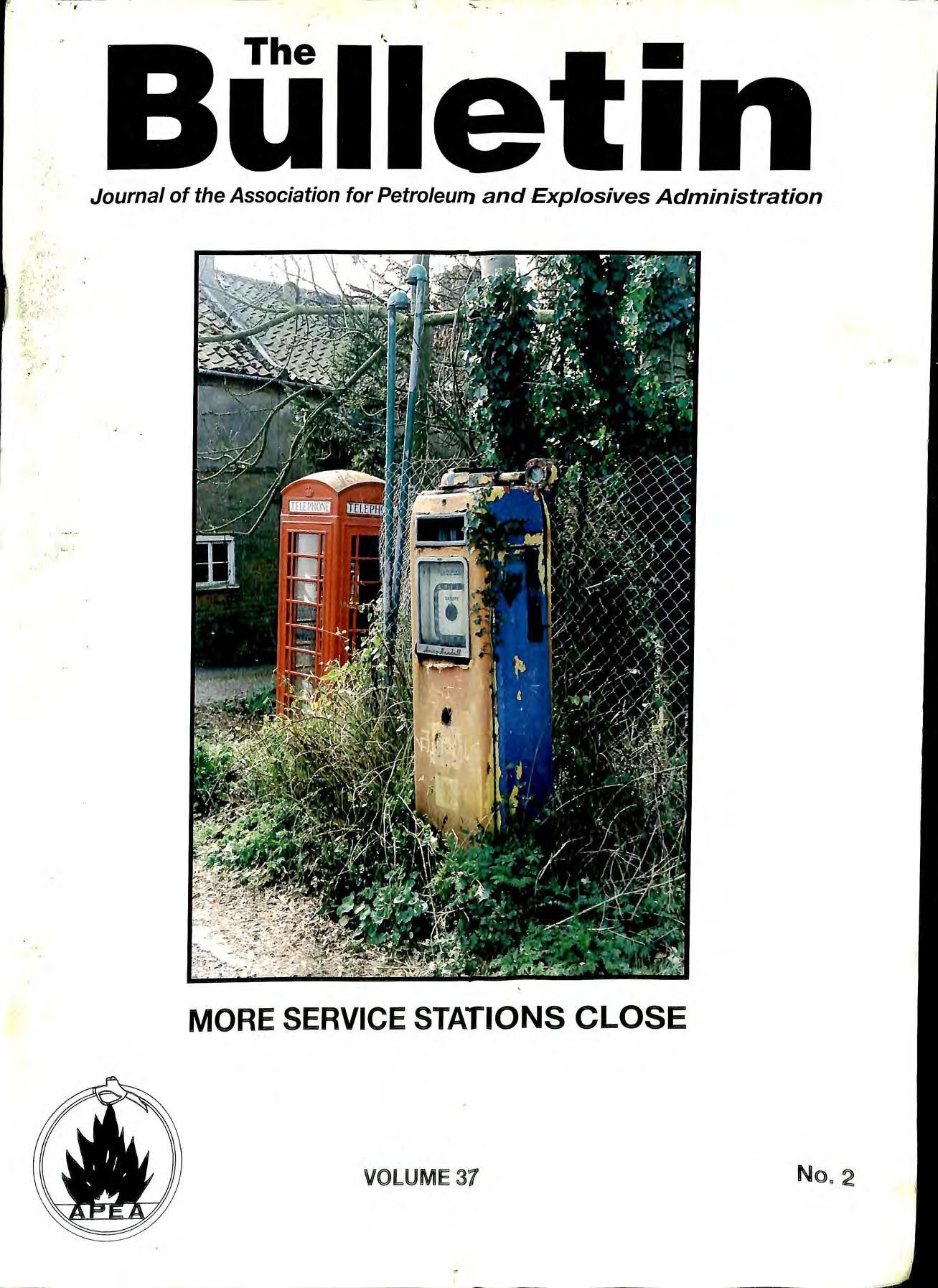
Journal of the Association for Petroleum and Explosives Administration
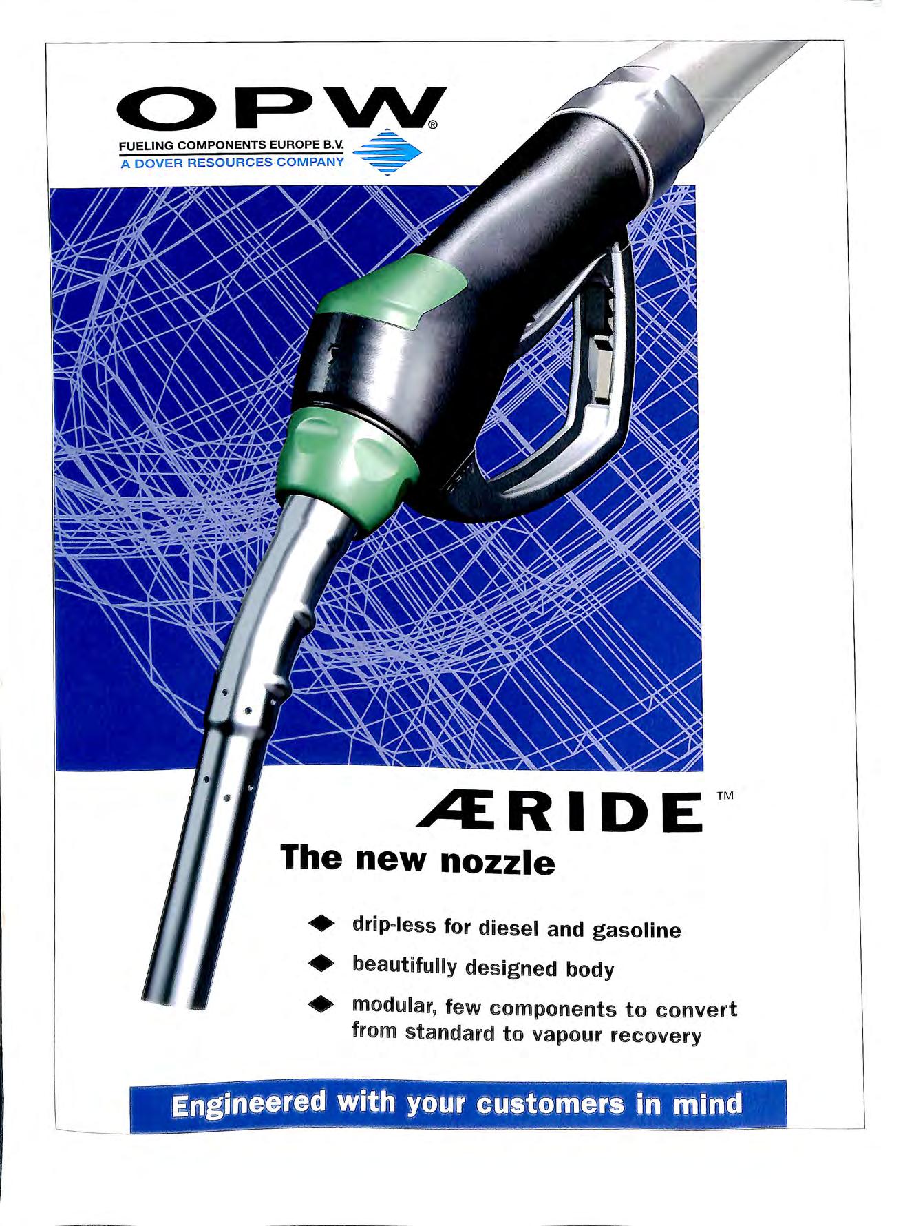
FUELING COMPANY A DOVER HES The new nozzle drip-less for d1ese . I and gasoline • • . ed body beautifully design nvert onents to co + modular, few comp our recovery from standard to vap ··- .i.
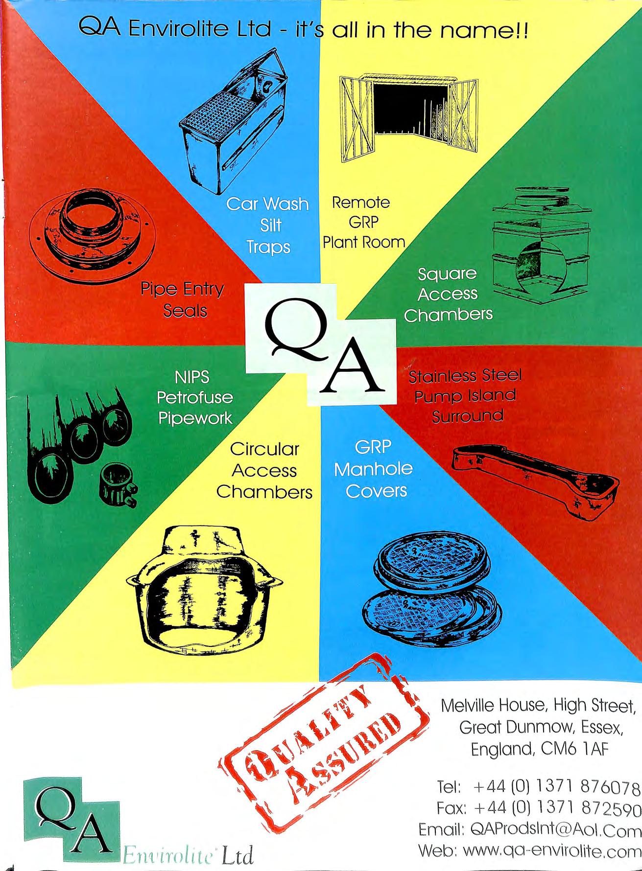
Access Chambers Remote GRP 't , Melville House, High Street, , Great Dunmow, Essex, England, CM6 l AF , Tel : +44 (0) 13 7 1 8 76 0 7 8 :_/ Fax: +44 (0) 13 7 1 872590 Email: QAProds lnt@Ao l.Com !boo.-.,~En tc " Ltd Web: www.q a -e nviro lite.corn
.. . ,f<·. i i • i' ii • I ' H I f '!f I 1:· . ·c .· ..._\.:_,.·pe1 ·.:t .··· .. 1 . __ tv ··. •.! ·· .· f.. . 1 •.d ·. "· · •. ' · I "' f! h,, n'If • 1·o1'1'I · m _ a.(•.;l;· .111ne • _ t liAll .· · ·=-. _ aft . ·.· -.1 'I ·1· 1 ,- ,.,. f 1·1 -1 , 11 1 • I i _.1 f -. ' t ,' . I • •I J. » • · I. ·./· 1 '· l I,,.,: · ·· P " ·--41 · • , ·• · · · • k f.l · • _·· va'd. 1 a _ I ,_:e ·tol• M r-· ___ _j -'· '.. 1 r· r· t .._ .- ...... __ ---v_·.,... .,.. , . . . I . . -.. t . ... , .. " .,-1 : •' 'f • '.'.' , . .: . . ", .·I, l .. ' . l ' . .·.' •, ••. ,litt ,o1• I : j# l i• ' 11_" 'O • 't j d • ·':-, Por ca ll rt-4 41 AO]·,· •. 41·.. t . ,- ' (··· ' •. •1· " • 'O f' . ' \• • "'' r •' ' f . • • A. • I ;,_ '1 ", I 1 : 1' ;' .\ ' ' !'\I.. l ·, : " ' l ; ' i0:1 i !/ ,_._ I\. ,-4 °"' \ •· ' ' I · ' [l) l\ . , 1\:_: . . . : :;.If • ' li!'i. ' • l" c ' :.t " ' • • . fil r.- ,.,. • . r _ ·,z,_ i., .. , ., . . I _ __
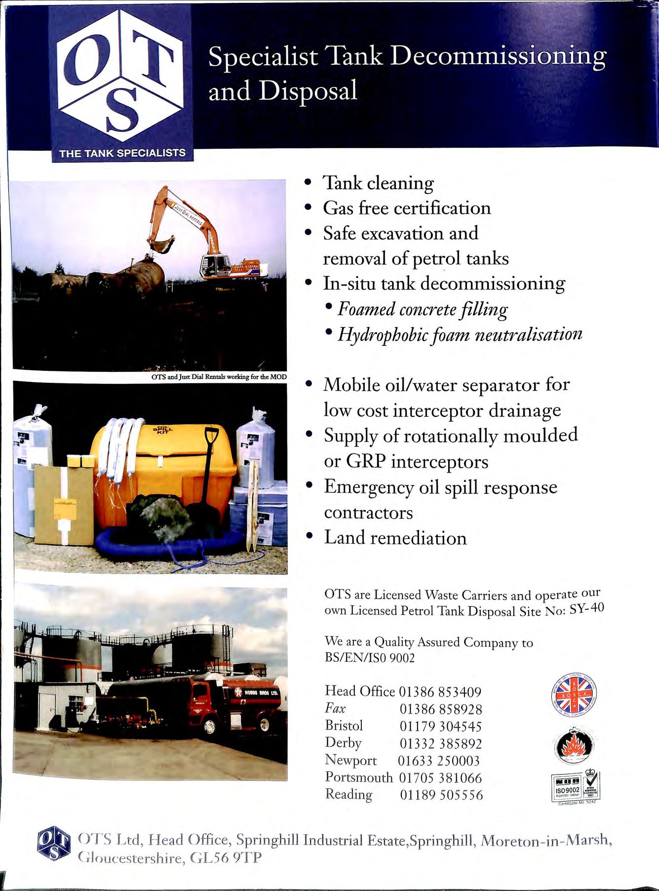
• Tank cleaning • Gas free certification • Safe excavation and removal of petrol tanks • In-situ tank decommissioning •Foamed concrete filling • Hydrophobic foam neutralisation • Mobile oil/water separator for low cost interceptor drainage • Supply of rotationally moulded or GRP interceptors • Emergency oil spill response contractors • Land remediation OTS are Licensed Waste Carriers and operate our own Licensed Petrol Tank Disposal Site No: SY-40 We are a Quality Assured Company to BS/EN/ISO 9002 Head Office 01386 8 53409 Fax 01386 8 58928 Bris t ol 011 79 304 54 5 Derby 0133 2 3858 9 2 N ewport 0163 3 25 000 3 Ports m outh 01 70 5 38 10 66 Re adi n g 0 1189 50 5556 ... " < 6 "'°""fD' OTS Ltd , I-lead Office, Springhill Industria l Esta t e,Springh ill, Mor e ton in Mar sh, V ( ; Joucestershire, GL56

High integrity pipework systems for forecourt installations Distri b uted by PURFLEET FORECOURT SERVICES PURFLEET FORECOURT SERVICES LTD 520 London Road West Thurrock, Grays, Essex RM2 0 3BE l!etrol·line -o_lus Durapipe - S&LP • No 1 UK manufacturer of polyethylene pipes • Superior electrofus ion jointing system • High flow rates • Available in four sizes for suction and pressure systems • Competitive prices • Nationwide delivery Tel: 01708 863931 Ext. 219 Fax: 0 1708 864140 co uk e mai l: purfleet forecou rt serv1ces@ hams-group. Ml LEDBURY WELDING & ENGINEERING LTD. Ml NEW MILLS INDUSTRIAL ESTATE LEADON WAY, LEDBURY HEREFORDSHIRE HR8 2SR (TEL: 01531 632222) 01 531 6347 1 8 ) A COMPLETE RANGE OF ABOVE & BELOW GROUND STORAGE VESSELS QUAUTY !UNDERGROUND TANKSDOUBLE AND SINGLE SKIN Ql!JAUTY UNDERGIROIUND TANIKS SPEC IA U ST COATI NG LEAK DETECTION OVERFILL PREVENTION DEVICES MANWAY ACCESS FRAMES MULTIPLE COMPARTMENTS ABOVE GRO!UJNlOi fFlUJll r B!UJNlDElD lOTAllV IENClO !ElD 6 DEIRV=PACK§ j 6(())(()) GAllON TO 20\0(())0 AllON . }

• • • • • • • • • THE COMPLETE FORECOURT SERVICE FROM SOME OF THE WORLD'S LEADING MANUFACTURERS Refurbishment & Retrofit Services Vapour Recovery Systems Petroleum Pipe Systems Drainage Products & Interceptors Paving Jet Wash & Air Systems Petrol Hose & Fixings Access & Inspection Chambers Tanks • • • • • • • • GRP Lightweight Covers Galvanized Steel Covers Double Skin Tanklining Signage Silt Traps GRP Multi Purpose Plant Rooms Pipe Entry Seals Pump Island Surrounds Fo r ecourt Furniture .................................................... And even more Tel: +44 (0) 1371 876078 Fax: +44 (0) 137 Po Box 4153, Melville House, High Street, Great Dunmow, Essex, CM6 1WE E-Mail: QAProdslnt@Aol.com Web: www.qa-envirolite.com Some supp li ers bes t enginee ri ng for a Secon dary Conta ined Tee Our engineering. We run the R&D giving vo u: Cost saving Time sav ing !)/ \ Ill' I \ II _, O \\\ H J l, J/ I ... Your choice ·· ··· ·· PETRO L PI PE SYS TEM. l)i ll ll1<' H(> 10- ()() l :l \ I Oh -\{)
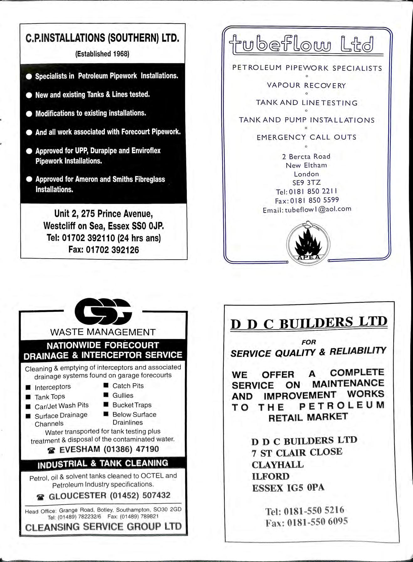
C.P.INSTALLATIONS (SOUTHERN) LTD. (Established 1968) e Specialists in Petroleum Pipework Installations. • New and existing Tanks & Lines tested. • Modifications to existing installations. e And all work associated with Forecourt Pipework. • Approved for UPP, Durapipe and Enviroflex Pipework Installations. • Approved for Ameron and Smiths Fibreglass Installations. Unit 2, 275 Prince Avenue, Westcliff on Sea, Essex SSO OJP. Tel: 01702 39211 O(24 hrs ans) Fax: 01702 392126 WASTE MANAGEMENT NATIONWIDE FORECOURT DRAINAGE & INTERCEPTOR SERVICE Cleaning & emptying of interceptors and associated drainage systems found on garage forecourts • Interceptors • Catch Pits • Tank Tops • Gullies • Car/Jet Wash Pits • BucketTraps • Surface Drainage • Below Surface Channels Drainlines Water transported for tank testing plus treatment & disposal of the contaminated water. ir EVESHAM (01386) 47190 INDUSTRIAL & TANK CLEANING Petrol, oil & solvent tanks cleaned to OCTEL and Petroleum Industry specifications GLOUCESTER (01452) 507432 Head Office : Grange Road , Batley, Southampton , 8030 2GD Tel (01489) 782232/6 Fax (01489) 789821 CLEANSING SERVICE GROUP LTD PETROLEUM PIPEWORK SPECIALISTS 0 VAPOUR RECOVERY 0 TANKAND LINETESTING 0 TANK AND PUMP INSTALLATIONS 0 EMERGENCY CALL OUTS 0 2 Bercta Road New Eltham London SE9 3TZ Tel : 0181 850 2211 Fax : 0181 850 5599 Email : tubeflow l@aol.com D DC BUILDERS LTD FOR SERVICE QUALITY & RELIABILITY WE OFFER A COMPLETE SERVICE ON MAINTENANCE AND IMPROVEMENT WORKS TO THE PETROLEUM RETAIL MARKET D DC BUILDERS LTD 7 ST CLAIR CLOSE CLAYHALL ILFORD ESSEX IGS OPA 0181 =55 0 5216 0181 =55 0 6095

r Forecourt Specialists Electrical Maintenance Design Testing Unit2 Gregory s Bank Trading E s tate Worc e ste r WR3 8AP TE L : 0 1 905 28402 FAX: 01905 28410 For safe handling and d isposa l. w CALL US F I RS T YE A RS EXPE RIENCE IN TH E PETROLEU M INDUSTRY RD TO GIVE YOU A QUALITY, PERSONAL SERVICE Professional developmen t TRAININ G IN-COMPANY SHORT COURSES • Electrical Requirements for Petrol Filling Stations • Management overview of HSW Statutory Regulations, including: Management of Health & Safety at Work Regs (MHSWR) Workplace Health, Safety and Welfare Regs (WHSWR) Provision & Use of Work Equipment Regs (PUWER) Personal Protective Equipment at Work Regs (PPER) • Essentials of Health & Safety at Work Sites • Introduction to Health & Safety Risk Assessment • ELECTRICITY AT WORK REGULATIONS (EWR) • Construction (Design & Management) Regs (CDM) • BS7671 Requirements for Electrical Installations (16th Edition Wiring Regulations) • Inspection and Testing of In-Service Electrical Installations • EARTHING AND BONDING Reviews a wide range of national Codes of Practice and Statutory Requirements Presenter. TERRY HEDGELAND BA FIE IE MIQ A. Me mbe r o f APEA and !O P Phone: 01737 553328 SPECIALIST BUILDERS TO THE PETROLEUM INDUSTRY • FORECOURT INSTALLATION INCLUDING STEEL & PLASTIC PIPEWORK • SHOP REFURBISHMENTS • ELECTRICAL INSTALLATION • MAINTENANCE AND REPAIR 01269 831038 FAX (01269) 831201 Acer Court , Cross Hands Business Park , Cross Hands ,Carmarthenshire SA146RE The As sociation for Petroleum and Explosives Administration
The introduction of Petrol-Line Vent Plus and Petrol-Line Plus Offset -and Fill pipes provides cost effective Offset Fill and Vent systems which comply fully with the IP Specification requirements .
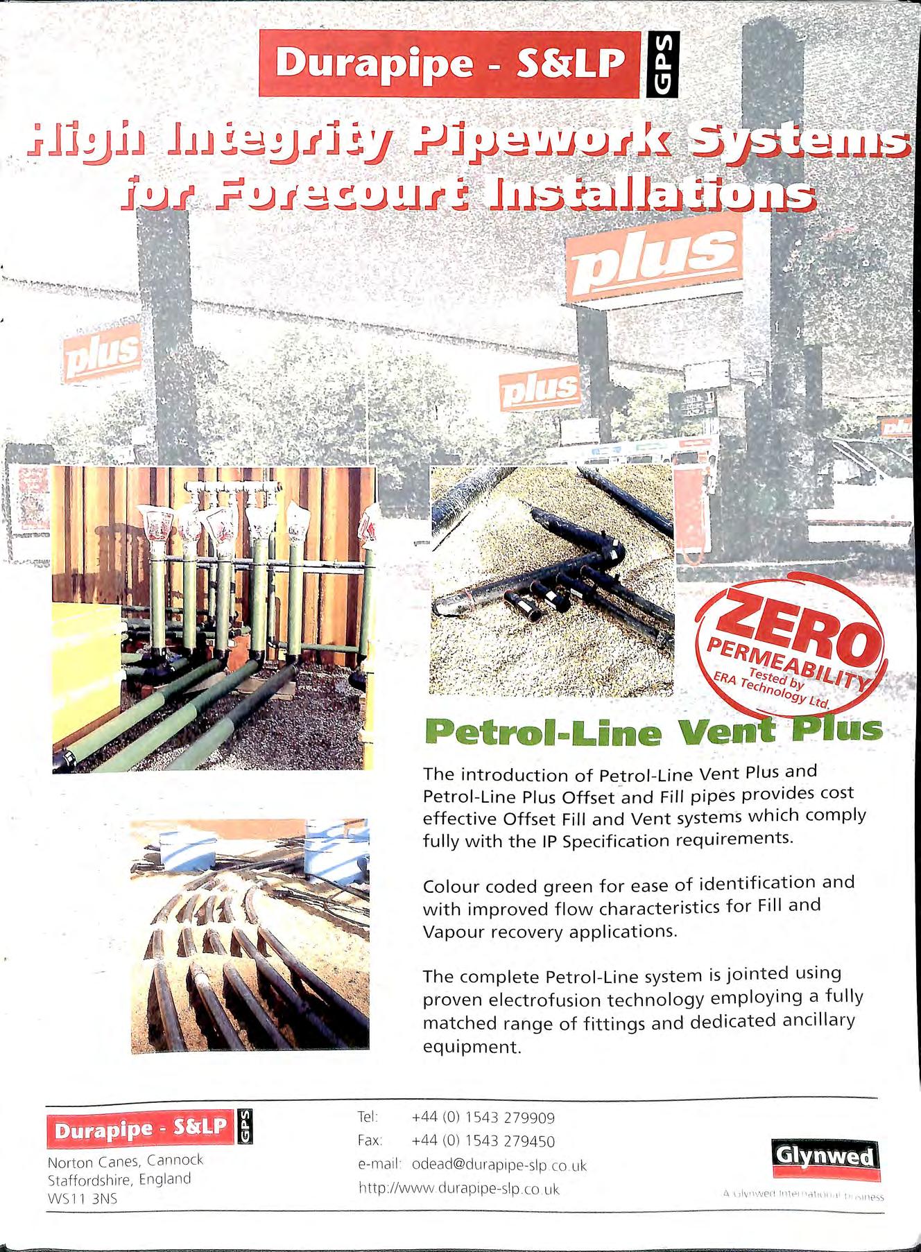
Colour coded green for ease of identification and with improved flow characteristics for Fill and Vapour recovery applications.
The complete Petrol Line system is jointed using proven electrofusion technology employing a fully matched range of fittings and dedicated ancillary equipment
(0) 1543 279909
(0) 154 3 279450 e- mail o dead@du rap 1pe-slp co uk http//www du1 apipe- slp co u k
i -_ No rto n Canes, Cannock St affordshire, England WS1 1 3NS ·"' " Te l Fax
+44
+44
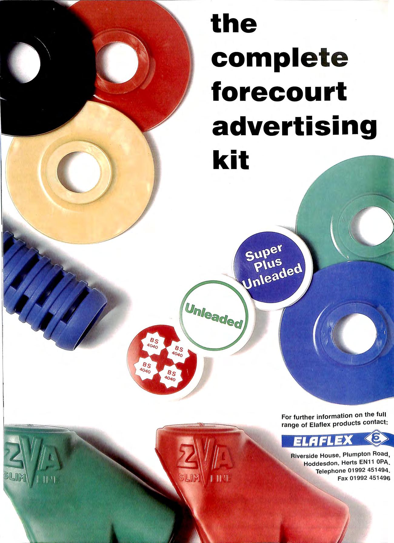
the complete forecourt advertising kit For further information on the full range of Elaflex products contact: Riverside House , Plumpton Road, Hoddesdon , Herts EN11 OPA. Telephone 01992 451494. Fax 01992 451496
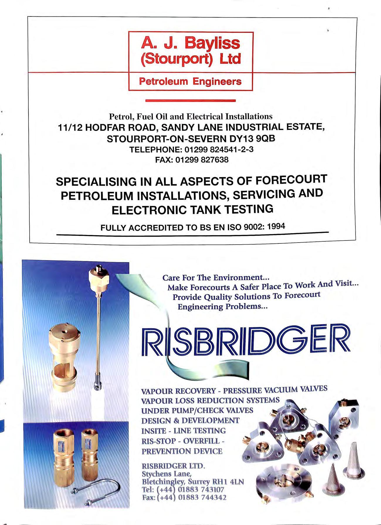
I· A. J. Bayliss {Stourport) Ltd Petroleum Engineers Petrol, Fuel Oil and Electrical Installations 11/12 HODFAR ROAD, SANDY LANE INDUSTRIAL ESTATE, STOURPORT-ON-SEVERN DY13 9QB TELEPHONE: 01299 824541-2-3 FAX: 01299 827638 SPECIALISING IN ALL ASPECTS OF FORECOURT PETROLEUM INSTALLATIONS, SERVICING AND ELECTRONIC TANK TESTING FULLY ACCREDITED TO BS EN ISO 9002: 1994 Care For The Envi r onment... Make Forecourts A Safer Place To Work And Vis it.. · Provide Quality Solutions To Fo r eco u rt Engineering Problems... RSBRllDGER VAPOUR RECOVERY - PRESSURE VACUUM VALVES VAPOUR LOSS REDUCTION SYSTEMS UNDER P UM P / CHECK VALVES DESIGN & DEVELOPMENT IN SITE UNE TESTING RIS-STOP - OVERFULL P lllEVENTION DJEV1ICJE RXSJBIUDGJER LTD §tychens Lame, §11mrey RlHl 4lN 'feR: ( +4 4 ij18 83 7 4 3107 lFax: (+44 !01883 744342
Sofitam Pump Services Ltd
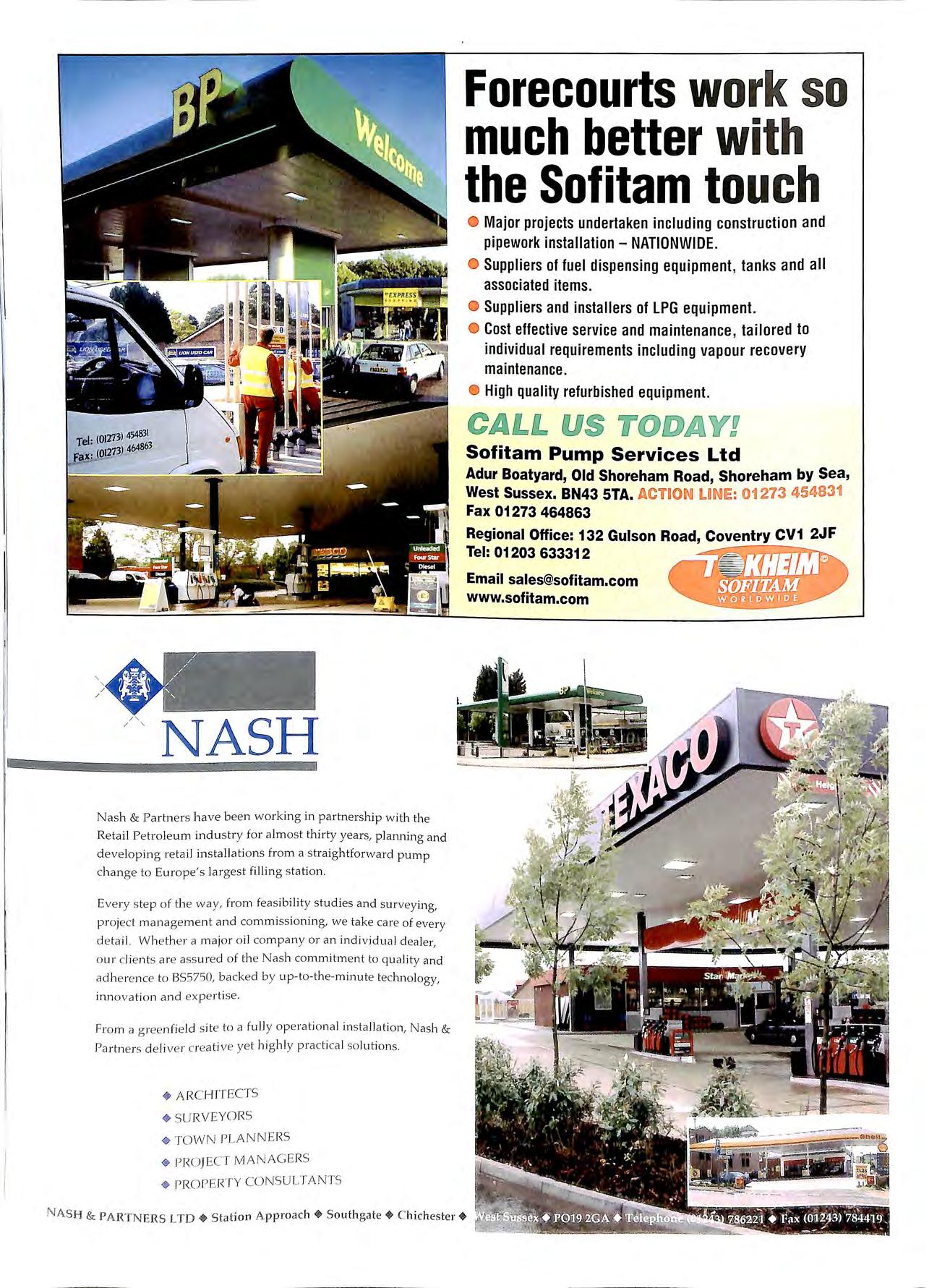
NASH Nas h & Partners have be e n working in partnership w ith th e Re tai l Pe tro leum indu s try for a lmo s t thirty years, planning and d eve lopin g reta il in s ta ll ations from a s traj ghtforward pump ch a n ge to Europe's largest fil lin g sta ti o n. Every s te p of the way, fr o m feas ib il ity studies and surveying, pr oject manageme n t and commissioning, we take care of every d e tail. Whether a major o il co mpan y or a n individua l deal e r, our cl ie nts are ass ured o f th e Nas h co mm ihnent to quality and ad h e re n ce to BS5750, back ed by up-to-the-minute technology, inn ova ti o n a nd expe rt ise. From a gree nfi e ld s ite to a full y ope rationa l in s tallation, Nas h & Partn e rs d e li ver c rea t ive ye t hi g hl y pra ctica l so luti o ns. + ARC HIT ECTS PLANNERS PJWJECT MA NAGE RS • PROPERTY CONSULT.ANTS Forecourts work
better with the
Major projects undertaken including construction and pipework installation - NATIONWIDE. Suppliers of fuel dispensing equipment, tanks and all associated items. Suppliers and installers of LPG equipment. Cost effective service and maintenance, tailored to individual requirements including vapour recovery maintenance. High quality refurbished equipment.
so much
Sofitam touch
Adur Boatyard, Old Shoreham Road, Shoreham by Sea, West Sussex. BN43 STA. ACTION UNIE: 01273 454831 Fax 01273 464863 Regional Office: 132 Gulson Road, Coventry CV1 2JF Tel : 01203 633312 Email sales@sofitam.com www.sofitam.com
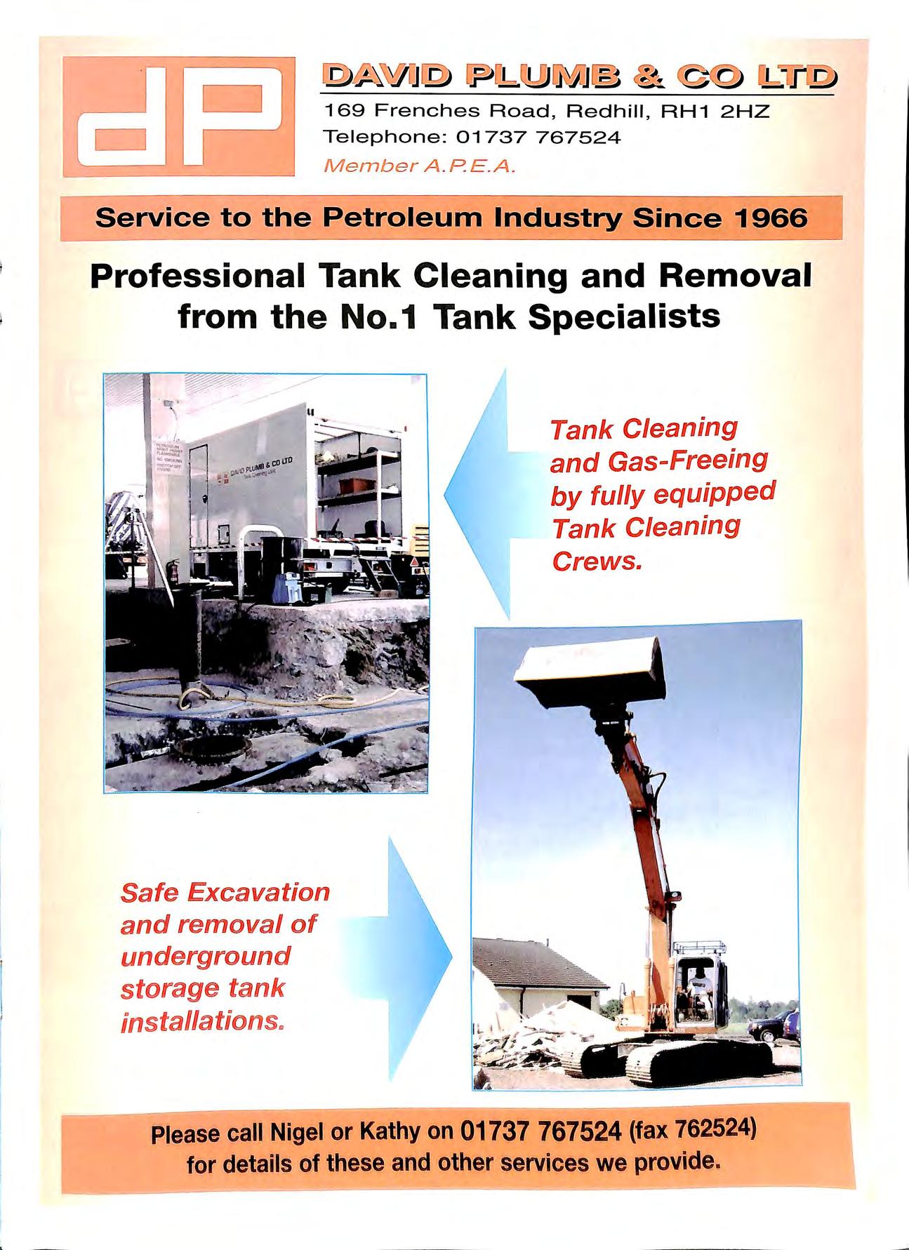
169 Frenches Road,
Telephone: 01737 767524 Member A PE A. Service to the Petroleum Industry Since 1966 Professional Tank Cleaning and Removal from th e N o.1 Tank Specialists Safe Excavation and removal of underground storage tank installations .. Tank Cleaning and Gas-Freeing by fully equipped Tank Cleaning Crews. Please call Nigel or Kathy on 01737 767524 (fax 762524) for details of these and other services we provide I
Redhill , RH1 2HZ
-· 'O C'> C'> Q) D') Q) c: c: ..c C'> 0 - CtS C'> "- CtS - - :l rJ) Q) 0 a: m :l "'O(/) "- Q) 0 'O s: c: s cn ·u i! a E ::s ,, Cl) .c .. .. ns i tl c Cl) E a. 0Cl) ,, 't: ::s a .e en ·Q) :t=e .a · -LI. Snaygill Industrial Estate Keighley Road Skipton N Yorkshire BD23 2QR United Kingdom T: + 44 (OJ 1756 799773 F: + 44(OJ 1756 799539 e m ail: covers @ fib reli ce .c om websi te: www fibreli t e com =========------------------------------------ ---j
NO-ONE ELSE WILL MAKE YOU A BETTER OFFER.
No other company is quite like Veeder-Root.
We're the world's leading supplier of tank gauges, wet stock reconciliation and leak detection systems. Our equipment monitors over 300,000 storage tanks throughout the globe. We supply most of the major oil companies, as well as supermarket groups and other major petrol retailers.
And no wonder. We built our reputation on developing leading-edge technology of outstanding quality Every tank gauge we
produce is proven to reliable, and easy to use.
We also listen to what our customers have to say. Our attitude to service, coupled with our wide range of gauges , means we can put together systems that are exactly right for you.
Call us on 0800 3285931 and talk to the experts in wet stock control and leak detection. You ' ll soon find that when it comes to great service, unbeatable products and real value , no-one has more to offer than Veeder-Root.
It VEEDER - ROOT Precise l y th e righ t deal f or your business .. Hydrex House , Garden Ro ad , Ric hm o nd , Surrey TW9 4 N R Tel: 44 (0) 181 39 2 1355 Fax : 44 (0) 181 878 6642
The
Published by the Association for Petroleum and Explosives Administration
A company Limited by Guarantee registered in England No. 2261660
Administrator: Brian Taylor
Opinions expressed in this Journal are not necessarily the views (Free to Members)
£10.00
Talking
ISSN 0263 4597 Website: www.apea.org.uk
The Bulletin in this issue is having to report on two products which have been causing some safety and environmental concerns. Although this is not always welcome for those involved, this industry takes safety and environmental issues seriously. If any good comes out of these situations it provides the manufacturer with an opportunity to put matters right, and renew the faith that industry had with these products.
AGM
The following post were filled at the AGM last month for 1999/2000:-
Chairman Ian Taylor Vice Chairman Ian Hiller Treasurer Mike Silmon Secretary Andy Berry Editor Jamie Thompson
SIMON
of the Association
VOLUME37 Number2 MAY 1999
Bulletin
Point
Contents TALKING POINT NOTES &NEWS PROSECUTIONS LPG DISPENSING AT PETROL STATIONS EXPLOSION PROTECTION NEW APPROACH PETROL DISPENSERS AND ATEX CONTAMINATED LAND VAPOUR RECOVERY PUMPS ABOVE GROUND TANKS APEA BRANCH SECRETARIES 32 33 37 39 44 48 50 52 56
WHITE SOUTHERN BRANCH MIKE SILMON NORTH EAST BRANCH SUE MEADOWCROFT WALES BRANCH
Chris Knight, Peter Allen, Paul Chawner and Phil Monger were all appointed to Council. MARTINIUSSEN EASTERN BRANCH RUTH SUTHERLAND SCOTLAND BRANCH DENNIS O'DEA MIDLANDS BRANCH
ANTON
BLANCHARD HUMBERSIDE BRANCH '. 1 '\RRY REID NORTH WEST BRANCH NATHANIEL MCCOY IRELAND BRANCH EDITORIAL TEAM
STEVE
32
ADVERTISING
.JAMIE
THOMPSON EDITOR
ROB GREEN
SECRETARY
notes & news
APEA CONTACTS GERMAN ASSOCIATION
Chairman John Boudry and Editor Jamie Thompson attended a meeting of the Bundesverband Behalterschutz (BBS) in Freiburg last month as o-uests of the President of b the Association Hans-Werner Harling .
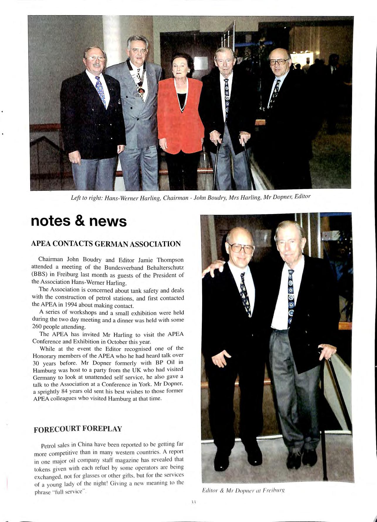
The Association is concerned about tank safety and deals with the construction of petrol stations, and first contacted the APEA in 1994 about making contact.
A series of workshops and a small exhibition were held during the two day meeting and a dinner was held with some 260 people attending.
The APEA has invited Mr Harling to visit the APEA Conference and Exhibition in October thi s year
While at the event the Editor recognised one of the Honorary members of the APEA who he had heard talk over 30 years before. Mr Dopner formerly with BP Oil in Hamburg was host to a party from the UK who had visited Germany to look at unattended self service, he also gave a talk to the Association at a Conference in York. Mr Dopner, a sprightly 84 years old sent hi s best wishe s to those former APEA colleagues who vi sited Hamburg at that time
FORECOURT FOREPLAY
Petrol sale s in China hav e bee n reported to be getting far more competitive than in many western countries. A report in one major oil compan y staff ma gazin e ha s re veal ed th at to kens g iven w ith e ac h refu e l by som e op erato rs are bein g exc han ged , not for glasses or oth er gift s but for th e se rvices of a yo un g lad y of th e ni g ht 1 G ivin g a new me anin g to th e ph rase " full se rvice"
Left to right: Hans-We rner Harling, Chairman John Baudry, Mrs Harling, Mr Dopn e1; Editor
Edi1 or & Mr Dopn e r at F' re ih 11 rg
, ,
LARGE FALL IN UK SERVICE STATION
NUMBERS
There have been further falls in the number of service stations in the UK at the end of 1998 the review by the Institute of Petroleum showed that 1066 service stations closed which equates to 3 sites per day closing. Indeed the figures already this year suggest this trend is continuing. There are now 13,758 service stations recorded at the end of 1998 and over the last 10 years 6258 sites have closed.
TEST RESULTS CONFIRM CONCERNS ABOUT PETROL PIPE SYSTEM
Results from tests carried out by ERA Technology the UK based test house has recently confirmed concerns in certain quarters about a polyethylene pipework system. The results show that the samples tested do not meet the requirements of the Institute of Petroleum specification in that permeation is exceeded. This has caused some concern amongst some oil company engineers, and has raised some questions about the validity of these certificates.
The LFCDA has already taken action by removing the acceptance of this product in London until the matter is resolved. The HSE is also considering the matter.
The Institute of Petroleum, regulators and ERA are meeting to set up a system to ensure that manufacturers are not able to get a pipe approved to the standard and then market a product which does not meet the standard.
CLIFFORD T. PEACOCK
It is with regret that we report the recent death at the age of 88 of Cliff Peacock, Chairman of the APEA in 1968-69 and Hon Treasurer from 1971 to 1980.
Cliff commenced his career in local government at Stockton Rural District Council in 1927. Upon qualifying as a Sanitary inspector he held appointments in the London area before returning to Yorkshire as chief public health officer, Hemsworth RDC in I 947.
Upon joining the APEA he was instrumental in the formation of the Yorkshire branch in 1965, being elected Secretaryffreasurer and branch representative.
It is. however, as the Hon Treasurer of the Association, a position he accepted upon his retirement in 1971, that he will be remembered. His was the stewardship, along with that of the Hon Secretary John Frid, that brought the Association through the difficult years following local government reorganisation in 1974.
He was a keen walker and naturalist and where better to engage in those activities than in the broad acres of his beloved Yorkshire.
A last memmy of Cliff In J 99'i he attended the Annual
Conference and Exhibition held at the NEC, Birmingham. A snapshot showed him at ease with the world, content in the knowledge that the Association was in good hands and fulfilling its aims as set out by those pioneers in 1958.
Bob Holdaway
UK SPEARHEADS DRIVE BY BP AMOCO FOR CLEANER MOTORING ACROSS THE WORLD
BP Amoco announced that its service stations in the UK are to be the first in its worldwide network to move en masse to selling new ultra-low-sulphur diesel.
The new fuel, which is already available at 75% of the company's 1,600 sites across Britain and is rolling out rapidly to the remainder, emits 90 per cent less sulphur dioxide and nearly a third less particulates and black smoke than standard diesel. It is also widely sold to BP's commercial customers.
BP Amoco is the first oil company to offer the new fuel, called BP Greener Diesel, on a countrywide basis and at no extra cost to customers.
Globally, the company said it intends to spend more than $100 million over the next two years modifying, refining and associated plant, to make its ultra-low-sulphur diesel available in more than 40 of the world's major cities most troubled by pollution and smog.
This is the first phase of a much larger investment which the company plans over the next six years to produce a range of cleaner fuels that maximise performance but minimise exhaust emissions.
The investment reflects a wider commitment by BP Amoco chief executive Sir John Browne to reduce greenhouse gases and other pollutants both from the company's own manufacturing operations and from the use of its products, particularly transport fuels.
Browne recently targeted a 10 per cent reduction from a I 990 baseline in emissions from BP's own operations by the year 20 I0. He also said the company would introduce cleaner motoring fuels including replacing 4-star petrol in the UK with an unleaded alternative by the end of the year and elsewhere within three years.
Browne today revealed plans to develop the UK's largest network of liquefied petroleum gas (LPG) outlets. with 70 sites planned by year-end and 300 within five years. BP Autogass is a light hydrocarbon fuel that delivers maximum efficiency in LPG and dual-fuel vehicles. whilst almost eliminating particulate emissions.
"As soon as possible we want the fuels we sell to be unleaded, low-benzene, low-sulphur or no sulphur." he said. "I believe we can show, year by year, that the products we supply contribute to a progressive improvement in air quality. without denying people the fundamental right of mobility"
..
BUDGET A MAJOR BOOST TO AUTOGAS: NOW 35.9p PER LITRE
Chancellor of the Exchequer, Gordon Brown turned political rhetoric into reality and confirmed the present government's green credentials by reducing excise duty on Autogas from 21.13p/kg to 15p/kg in his budget announcement at the beginning of March . This means a 29% reduction, and provides the LPG industry in this country with the firm governmental endorsement that it needed to further enhance the effects of the freeze on duty over the past two years. At the same time, duty on petrol and diesel has been increased by 6% over inflation.
The news was greeted wannly by the LP Gas Association, who felt that its strenuous efforts in lobbying the Treasury had finally paid off. "The budget goes a long way toward meeting the request from the LP Gas Association and gives a major boost to our industry," said Tom Fidell, the director general of the LPGA.
These sentiments were echoed by the major fuel suppliers A spokesperson for BP said that the announcement was "most welcome, and sure to increase the demand for Autogas in the coming months. A demand that BP are prepared to meet."
Flogas has been swamped with telephone enquiries by fleet managers since the Budget, asking after installation of Autogas refuelling facilities. David Brice, field sales manager for the company said that "the waiverers from amongst the fleet managers will now be coming to Autogas ," and he applauded the LPGA for all the hard work that it had put in.
With 3 9 pence per litre added to premium unleaded petrol, and 3.07 pence cut from LPG, LPG Autogas is now priced at 35.4p per litre at Jet service stations , compared with around 65p per litre for premium unleaded. And as we know from previous Budgets and from the Government ' s stated long-term policy, this differential will increase in future years.
PUMPTRONICS AUTOGAS DISPENSERS
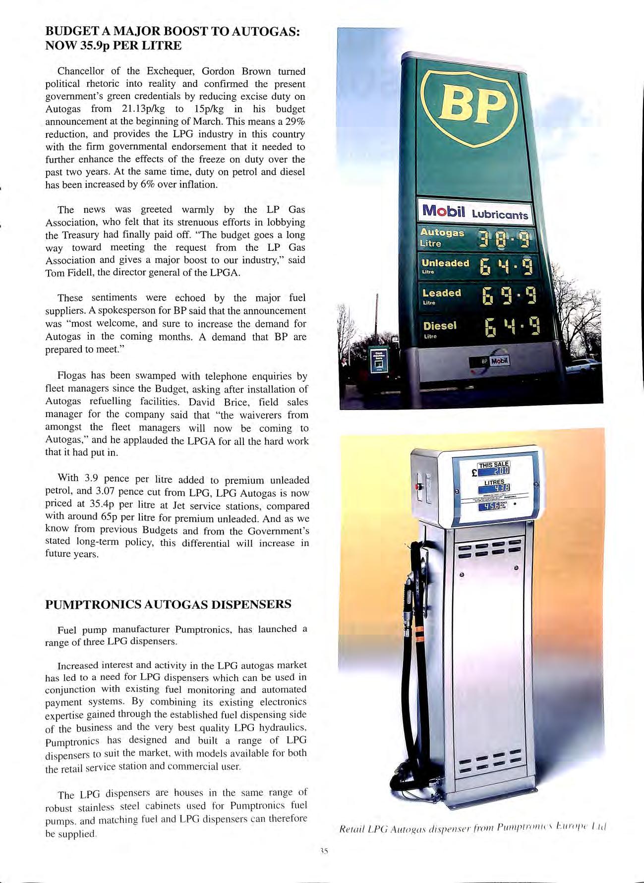
Fuel pump manufacturer Pumptronics , has launched a range of three LPG dispensers.
Increased interest and activity in the LPG autogas market has led to a need for LPG dispensers which can be used in conjunction with existin g fuel monitoring and automated payment systems. By combining it s existing electronics experti se gained through the establi shed fuel dispen sing side of the business and the very best quality LPG hydrauli cs , Pumptronic s ha s de signed and built a range of LPG di spensers to suit the marke t, with models available for both the retail se rvic e station and co mmercial use r.
Th e LPG di spen se rs are hou se s in th e sa me rang e of robu st stainless stee l cabinets use d for Pumptroni cs fu el pumps , and matching fue l and LP G dispensers can the refo re be suppli ed
R e toi l LPG Auro g o s disp n 1s!! 1 f lm11 P111111Jr ro11 i n E111np c l .1r/
PETROL PUMPS - PUBLIC SAFETY ISSUE
ZVA Slimline nozzles Fatigue Failures of Swivels
In the UK there have been 26 incidents reported to Elaflex over a period of 2 years where standard swivels and safety break swivels have separated on th ZVA Slimline nozzle during operation. This has resulted in customers being sprayed with petrol and caused spills on forecourts. There have been other incidents in Ireland and Portugal but there have so far been no reported incidents in other European countries.
Technical Background
Investigations and tests were carried out which involved Elaflex co-operating with the London Fire Brigade, Esso Petroleum and BP Amoco. The failures could not be traced back to drive-in or drive-off incidents. The failed swivels all showed signs of metal fatigue cracks. The cracks started in the groove of the circlip holding the swivel nut and grew until the final rupture.
(I) All reported incidents in the UK have occurred with nozzles assembled to wire braided hoses. There have, so far, been no reported incidents with standard swivels fitted to textile braided hoses.
The Universities of Surrey and Hanover independently conducted measurements of the pressure peaks in the swivel area. It has been established that pressure peaks at nozzles with wire braided hoses are as much as 10 bar higher than with textile braided hoses. Pressure peaks of 32 bar have been recorded at the joint in the tests at Surrey University for micro seconds, using the Elaflex nozzle.
(2) Incidents of failed safety break swivels SSBl6 were reported failing after only one years service, however incidents with standard swivels EA 175 (after 98 EA 075) failing occurred normally after at least 5 years of operation. The reason for the former is that the aluminium alloy of the safety brake swivel contained lead until production end I 997 and therefore was more susceptible to fatigue hreaks.
Since the production of the easy rotating ivel EA 075 from production period first quarter 98, the aluminium alloy and the construction of standard swivels and safety hrcak swivels have heen standardised and are identical.
<1 J Si nee March J 999 Elaflex have strengthened the construction of the standard swivel EA 075 and the safety hreak swivel SSB 16 (production marked :99J This construction change increased the service life to I()- 15 even when used with wire hraided hoses.
(4) Since the end of April 1999 further modifications are made warranting an infinite service life for use with all types of hoses. (Production marked .: 99)
Action Plan
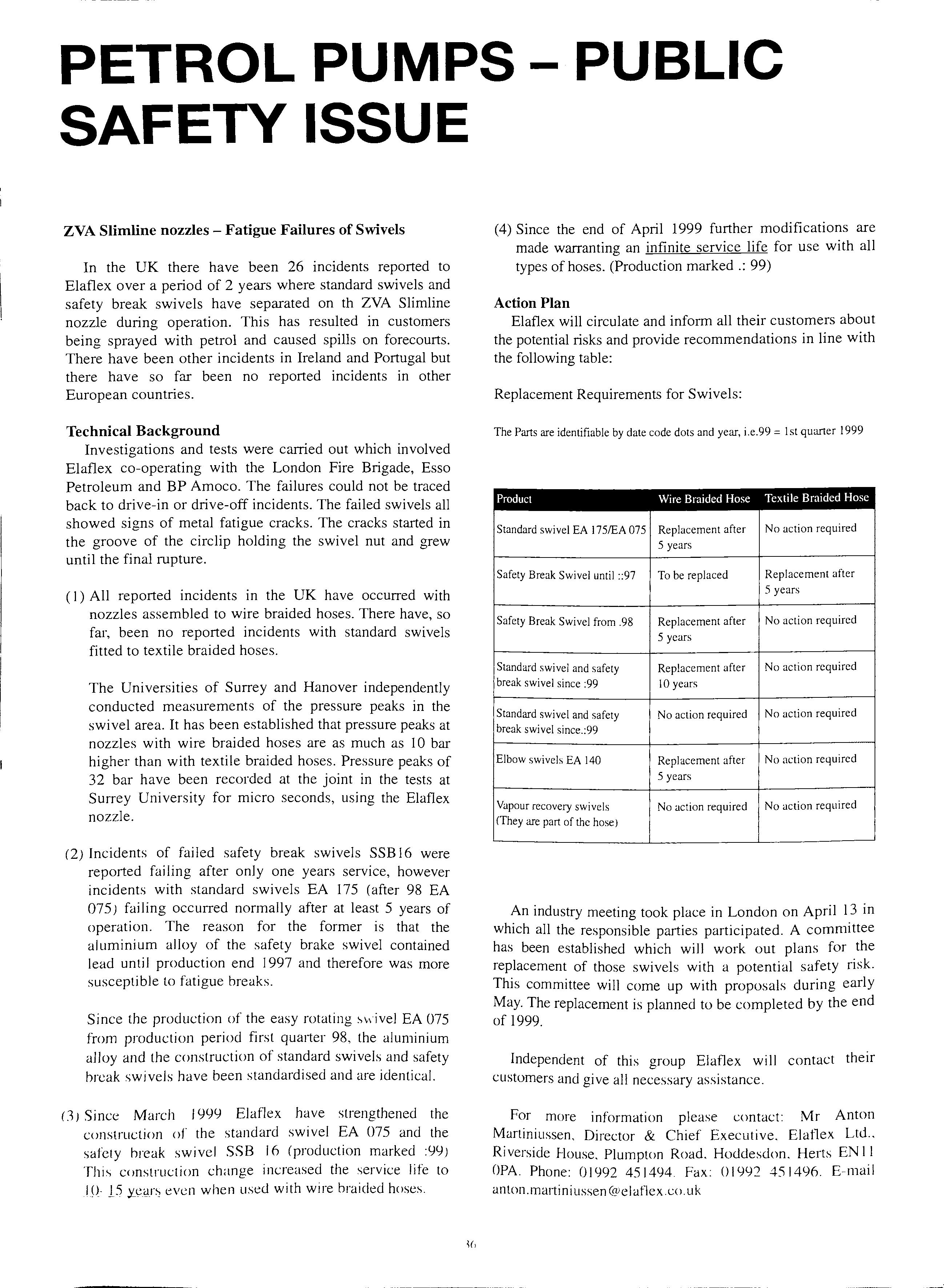
Elaflex will circulate and inform all their customers about the potential risks and provide recommendations in line with the following table:
Replacement Requirements for Swivels:
The Parts are identifiable by date code dots and year, i.e. 99 = l st quarter 1999
Product Wire Braided Hose Textile Braided Hose
Standard swivel EA 175/EA 075 Replacement after No action required 5 years
Safety Break Swivel until ::97 To be replaced Replacement after 5 years
Safety Break Swivel from .98 Replacement after No action required 5 years
Standard swivel and safety Replacement after No action required break swivel since :99 10 years
Standard swivel and safety No action required No action required break swivel since.:99
Elbow swivels EA 140 Replacement after No action required 5 years
Vapour recovery swivels No action required No action required (They are part of the hose)
An industry meeting took place in London on April 13 in which all the responsible parties participated. A committee has been established which will work out plans for the replacement of those swivels with a potential safety risk. This committee will come up with proposals during early May. The replacement is planned to be completed by the end of 1999.
Independent of this group Elaflex wi 11 contact their customers and give all necessary assistance.
For more information please contact: Mr Anton Martiniussen, Director & Chief Executive. Elaflex Ltd., Riverside House. Plumpton Road, Hoddesdon. Herts EN I I OPA. Phone: 0 I992 45 I494. Fax: 01992 451496. E-mail an ton. marti niussen (<velatlex.co. uk
PROSECUTIONS
ESSO POLLUTION FINE
Esso has been ordered to pay a fine of £13,800 by Wimbourne magistrates for polluting undercrround water b with thousands of gallons of petrol following a leak at a forecourt in Dorset.
The forecourt's operator noticed discrepancies in fuel storage figures between 11 and 15 July last year and notified Esso. On 31 July contractors brought in by the oil company identified the leak in a worn underground pipe and also found that the leak detection system had failed.
On 03 August the Environment Agency was informed by J?orset County Council Trading Standards that up to 7,000 litres of unleaded fuel had leaked into the ground at the Lake Gates service station on the A3 l road near Wimbourne.
The forecourt is located 1 mile from an imp011ant drinking water source for Poole, and the Environment Agency informed Wessex Water, Bournemouth & West Hants Water and East Dorset District Council Environmental Health. The water abstraction point was closed as a precaution.
Esso's plans for the recovery of fuel and clean up of contamination was supervised by environment protection officers from the Agency. The fuel storage tanks were removed and replaced and a treatment system was installed to clean up contaminated water below ground. The recovery operation is still underway with an estimated 5-6,000 litres of fuel still to be recovered. Environmental Agency spokesman Bridget Norris said: 'There was a delay between the leak happening and the Environment Agency finding out. Esso didn't tell us. We found out almost by accident via the local council. That shouldn't happen in future with the new powers we have been given.'
The Agency says such incidents are far from isolated. Many of the 14,500 filling stations in Britain are old and underground tanks and pipes are rusty.
'The scale of the problem appalls us,' said the Agency's hydro-geologist Jonathan Smith.
'Until now, legislation hasn't allowed us to do anything about installations, even if we fear they might be too old. We could only wait until they leaked. but by then it might be too late.'
As 30 to 35 per cent of drinking water comes from groundwater, petrol leaks near to underground reservoirs can have major repercussions. The safe level for pollution is only 1O parts per billion. That means only one or two litres of leaked petrol can pollute thousands of gallons of water.
OIL COMPANY PROSECUTED FOR THE INADEQUATE TRAINING OF 'COMPETENT PERSON'
The inadequacy of the training for 'competent persons' as required by Regulation 8(2)(a) of Schedule 12 to the Carriage of Dangerous Goods by Road Regulations 1996 (COG) came to light during an investigation into a spillage of petrol that occurred on 10 April 1998 at the Jet filling station in Yeadon near Leeds.
At 2249 hours on 11 April 1998 the West Yorkshire Fire Service received a 999 emergency call from the night attendant at the filling station complaining of a severe smell of petrol in the shop.
On arrival at the filling station the responding firefighters were met with a very strong smell of petrol when they entered the shop. As the night attendant was unaware of any recent spillages, the firefighters inspected the interceptors and all the fill point chambers for evidence of any leakages. When they removed the cover of one of the storage tank fill points they found the chamber to be almost full to the top with neat petrol.
The duty Fire Safety Officer (FSO) was summoned to the incident and when he obtained a reading of 25% LEL on the gas detector, ordered the site to be closed and the premises to be evacuated for the remainder of the night.
The source of the petrol vapours_ entering shop through the conduit in the electrical cab111et was presumed to be from the residual product f?und_ 111 the storage tank fill chamber. To alleviate_ the and prevent any possible off-site hrehghters 'set-to' and manually baled out. with111 reachmg distance. approximately 50 litres of petrol from the deeper than average chamber.
When on the following day a specialist contractor had pumped out a further 30 litres of petrol from the chamber and the vapours in the shop had fallen below 1% LEL. the FSO allowed the site to re-open for business.
The unaccountable presence of some 80 litres of neat petrol was the subject of a full investigation by Petroleum Officers of the West Yorkshire fire Service. Initially their enquiries found there had been a delivery on the clay before the incident ( 1() April). Subsequent interview:-. ot the tanker driver. the two attendants who supen ised the delivery and representatives of the licensee identified a combination of circumstances which gave rise tu an unseen spillage (outtlovv) of petrol during the lk\1\t'r\ un 10 Apri I 1
The conclusion of the investigation, which included two trial deliveries, was that the cause of the spillage was primarily due to the recklessness of the tanker driver in failing to re-connect the vapour balance hose after he repositioned his road tanker; thereby over pressurising th vapour balancing system. This omission was exacerbated on two counts by others involved in the unloading process. Firstly by the failure of the 'competent person ' (who supervised the commencement of the delivery) to replace the fill pipe cap of the first tank to receive product which had accidentally been dropped into the deep chamber during stock checks the previous day. This mistake allowed product to outflow (unseen) from the pressurised system after the chamber cover had been replaced. Secondly by the inexperienced attendant who took over supervision duties part way through the delivery, when she permitted the unloading to continue in the knowledge that the driver had failed to reconnect the vapour balance hose.
A further significant factor that pl aye d a major part in the circumstances giving rise to the spillage, and an offence for which the Fire Authority subsequently charged the company with, was the inadequacy of the training given to the appointed 'co mpetent person' following the retro-fitting of a Stage 1b vapour balanc ing system some 12 months prior to the spillage.
On 19 March 1999, Conoco Ltd pleaded guilty at the Pudsey Magistrates Court to a charge of 'failing to ensure that the 'com petent person' had received adequate trainina b m accordance with the requirement s of 'Regulation 8(2)(a) of Schedule 12 CDG'. The Magi strates imposed a fine of £1000 an d awarded £2,304.94 prosec ution cost to the Fire Authority.
With the tanker driver being di smissed as a consequence of hi s misconduct, the Fire Authority decided not to take any action aga inst him for an offence contrary to Regulation ll (c) of Schedule 12 CDG.
R Marri s Assistant Divisional Officer We st Yorkshire Fire Service
NEW
PUMP
MODELS INCREASE RANGE AND AFFORDABILITY OF PUMPTRONICS
PUMPS
Pumptronics has introduced into its range of fuel pumps a new Standard design which offers customers a more affordable styling option than the units which were launched in 1998.
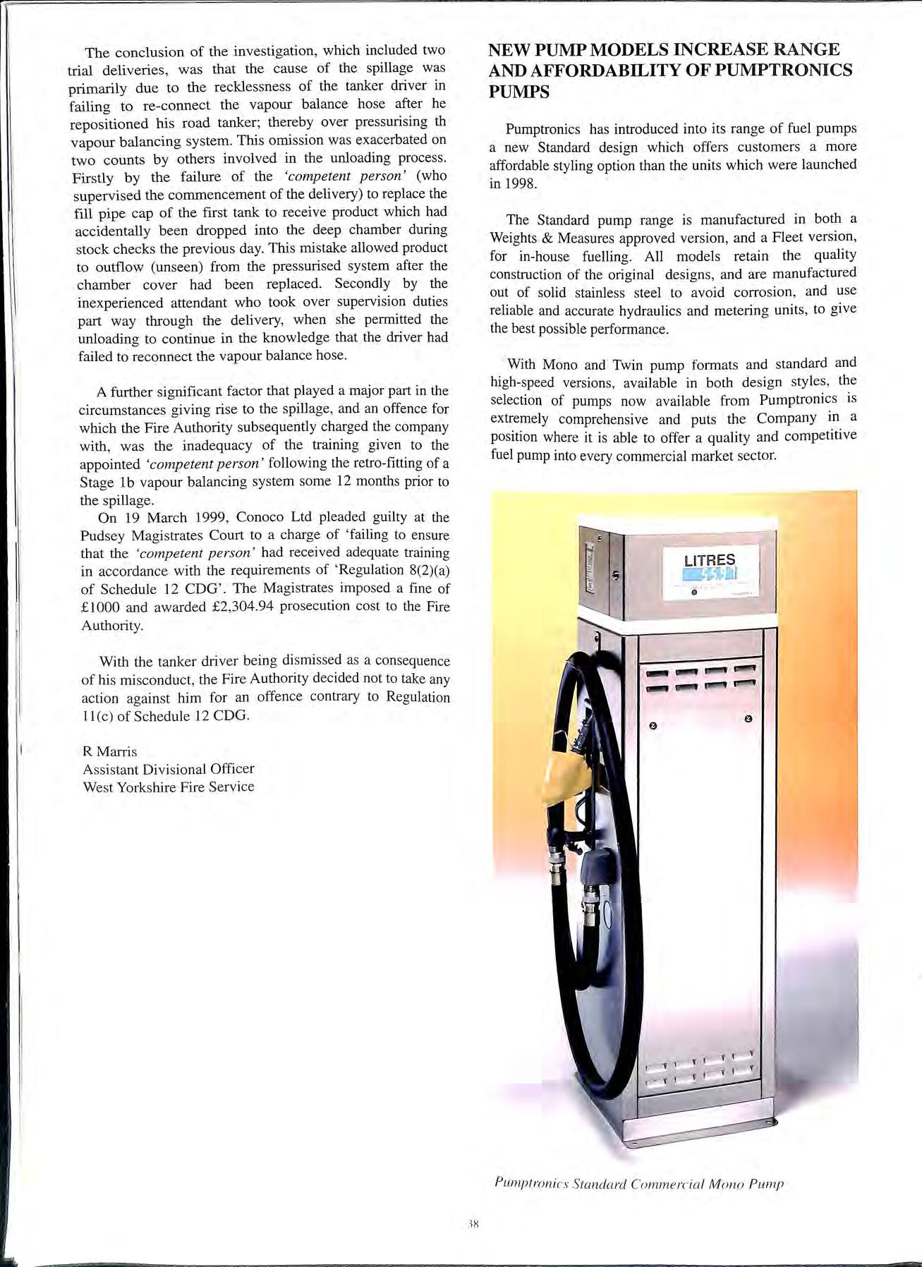
The Standard pump range is manufactured in both a Weights & Measures approved version, and a Fleet version, for in-house fuelling. All models retain the quality construction of the original designs, and are manufactured out of solid stainless steel to avoid corrosion, and use reliable and accurate hydraulics and metering units , to give the best possible performance
With Mono and Twin pump formats and standard and high-speed versions, available in both design styles, the selection of pumps now available from Pumptronics is extremely comprehensive and puts the Company in a position where it is able to offer a quality and competitive fuel pump into every commercial market sector.
- ---!"ii"
LITRES
Pumptroni c. 1 · Standard Commercia l Mono Pump
.18
SAFETY CONSIDERATIONS IN THE STORAGE AND DISPENSING OF LPG AS A FUEL FROM THE FORECOURT
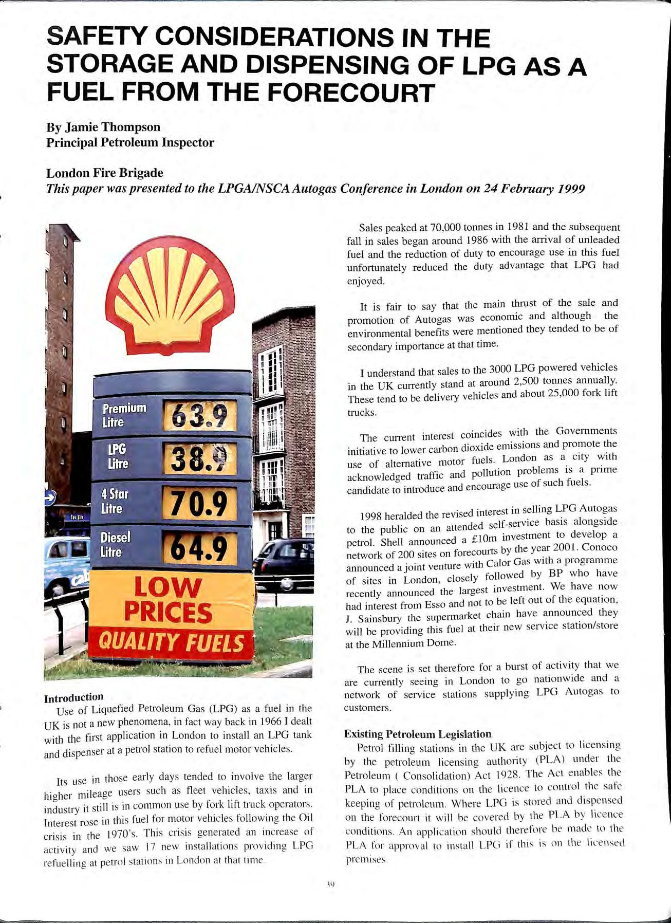 By Jamie Thompson Principal Petroleum Inspector
London Fire Brigade
By Jamie Thompson Principal Petroleum Inspector
London Fire Brigade
This paper was presented to the LPGAINSCAAutogas Conference in London on 24February1999
Sales peaked at 70,000 tonnes in 1981 and the subsequent fall in sales began around 1986 with the arrival of unleaded fuel and the reduction of duty to encourage use in this fuel unfortunately reduced the duty advantage that LPG had enjoyed.
It is fair to say that the main thrust of the sale and promotion of Autogas was economic and although the environmental benefits were mentioned they tended to be of secondary importance at that time.
I understand that sales to the 3000 LPG powered vehicles in the UK currently stand at around 2,500 tonnes annually. These tend to be delivery vehicles and about 25,000 fork lift trucks.
The current interest coincides with the Governments initiative to lower carbon dioxide emissions and promote the use of alternative motor fuels. London as a city with acknowledged traffic and pollution problems is a prime candidate to introduce and encourage use of such fuels.
1998 heralded the revised interest in selling h bi ttended self-service basis alongside to t e pu ic on an a I Sh II d a £1 0m investment to develop a petro . e announce network of 200 sites on forecourts by the year 2001. Conoco announced a joint venture with Calor Gas with a progra1rune · · J I "ollowed by BP who have of sites m London, c ose y 1' recently announced the largest investment. We have now had interest from Esso and not to be left out of the equation, J. Sainsbury the supermarket chain have they will be providing this fuel at their new service station/store at the Millennium Dome.
Introduction
Use of Liquefied Petroleum Gas (LPG) as a fuel in the UK is not a new phenomena, in fact way back in 1966 I dealt with the first application in London to install an LPG tank and dispenser at a petrol station to refuel motor vehicles.
Its use in those early days tended to involve the higher mileage users such as fleet vehicles, taxis and in industry it still is in common use by fork lift truck operators. [nterest rose in this fuel for motor vehicles following the Oil crisis in the I 970 's. This crisis generated an in c rease of activity and we saw 17 new installations providing LPG refuelling at petrol station s 111 London at that tim e.
The scene is set therefore for a burst of activity that we are currently seeing in London to go nationwide and a network of service stations supplying LPG Autogas to customers.
Existing Petroleum Legislation
Petrol filling stations in the UK are subject to licensing by the petroleum licensing autho1ity (PLA) under the Petroleum ( Consolidation) Act 1928. The Act enables th e PLA to place conditions on the li ce nc e to co ntrol th e safe keeping of petroleum Where LPG is stored and disp e ns ed on the forecourt it will be covered by the PLA b y li ce nce co ndition s. An application should therefore b e mad e \l) the PLA for approval to install LPG if this is on the li ce ns e d premises
The PLA's range from Metropolitan Fire Authorities such as the LFCDA which has specialist inspectors and is the largest PLA in the UK to the smaller Unitary Authorities who may have only recently taken on the task following local government reorganisation. The enforcing officers generally come under the Fire Authority, Trading Standards or Environmental Health.
Planned changes in the legislation programmed to take place on lst April 1999 have recently been shelved. The Acts will continue to be in force until at least the year 2001. A full review of all flammable and explosives legislation will now take place to enable new UK legislation to be in force during 2001 to support the EC Chemical Agents Directive.
LPG VPetrol
The chemical substance most commonly involved in operational incidents in London is Liquefied Petroleum Gas (LPG), followed by Petrol.
Operational Incidents in the London Fire Brigade 1998
LPG 133
Petrol 100
LPG operational incidents mainly involve cylinders which at present are the most common form of access to the Gas, these ranged from domestic incidents to some more serious industrial fires.
Petrol in comparison gave us slightly fewer incidents and ranged from petrol smells in houses to a 27 ,OOO litres loss which invoked a major incident procedure.
Petrol is by far the most common hazardous substance that the general public have ready access to, and in excess of 24 million tonnes are purchased by the consumer each year from petrol filling stations. It is a task carried out daily by the vast majority of the adult population of the UK.
The use of LPG for refuelling vehicles is minute (2,500 tonnes) in comparison, but as you will already have heard today this figure is likely to grow as LPG use is encouraged.
Fuel Characteristics
Lower/upper flammability limits
Auto ignition temperature Density relative to Air
LPG Petrol
2.2 to 10% 460 to 550°C 1.4 to 1.55
AUTOGAS
The hazards of storing and dispensing LPG are reasonably well known and although in the UK we may not have the breadth of experience that we have in dispensing petrol, the knowledge of Autogas and the experience in other countries assist us in this area.
LPG is used quite extensively in Europe with 5500 service stations dispensing LPG. It is estimated that over l million motorists in Italy and 112 million in the Netherlands regularly use LPG powered vehicles. There is also widespread use in Belgium and France.
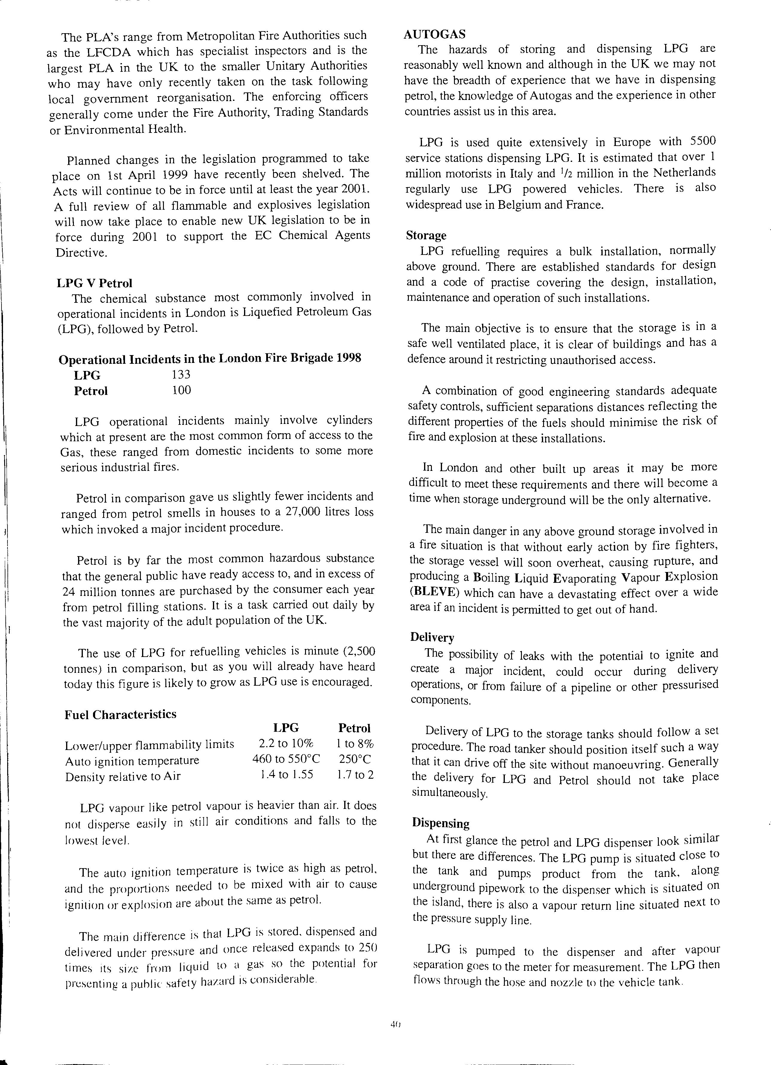
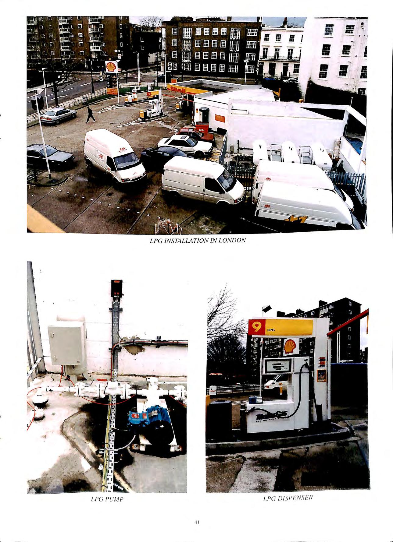
Storage
LPG refuelling requires a bulk installation, normally above ground. There are established standards for design and a code of practise covering the design, installation, maintenance and operation of such installations.
The main objective is to ensure that the storage is in a safe well ventilated place, it is clear of buildings and has a defence around it restricting unauthorised access.
A combination of good engineering standards adequate safety controls, sufficient separations distances reflecting the different properties of the fuels should minimise the risk of fire and explosion at these installations.
In London and other built up areas it may be more difficult to meet these requirements and there will become a time when storage underground will be the only alternative.
The main danger in any above ground storage involved in a fire situation is that without early action by fire fighters, the storage vessel will soon overheat, causing rupture, and producing a Boiling Liquid Evaporating Vapour Explosion (BLEVE) which can have a devastating effect over a wide area if an incident is permitted to get out of hand.
Delivery
The possibility of leaks with the potential to ignite and create a major incident, could occur during delivery operations, or from failure of a pipeline or other pressurised components.
I to 8% 250°C 1.7 to 2
LPG vapour like petrol vapour is heavier than air. It does not disperse easily in still air conditions and falls to the lowest level.
The auto ignition temperature is twice as high as petrol, and the proportions needed to be mixed with air to cause ignition or explosion are about the same as petrol.
The main difference is that LPG is stored. dispensed and delivered under pressure and once released expands to 250 times its site from liquid to a gas so the potential for presenting a puhl ic safe! y hazard 1s considerable
Delivery of LPG to the storage tanks should follow a set procedure. The road tanker should position itself such a way that it can drive off the site without manoeuvring. Generally the delivery for LPG and Petrol should not take place simultaneously.
Dispensing
At first glance the petrol and LPG dispenser look similar but there are differences. The LPG pump is situated close to the tank and pumps product from the tank, along underground pipework to the dispenser which is situated on the island, there is also a vapour return line situated next to the pressure supply line.
LPG is pumped to the dispenser and after vapour separation goes to the meter for measurement. The LPG then flows through the hose and nozzle to the vehicle tank.
, I
411
= • .. -... ,..,, .. ••a • , ! ...,- :. • - I • •• • • •
LP G D IS P EN S ER .+ I
L PG INSTALLATION IN LOND ON
LPG PUMP
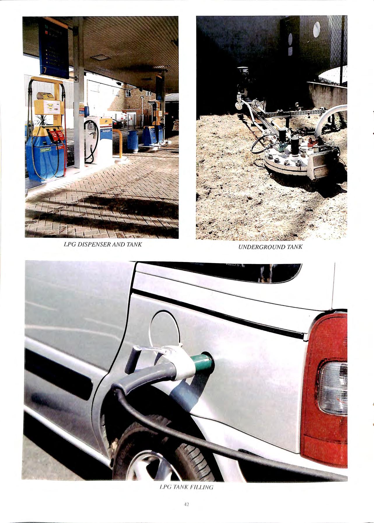 LPG DISPENSER AND TANK UNDERGROUND TANK
42
LPG TANK FILLIN G
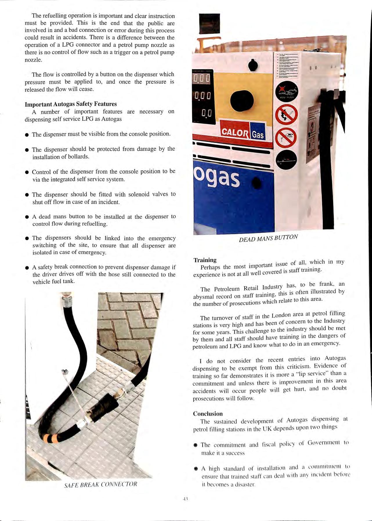
The refuelling operation is important and clear instruction must be provided. This is the e nd that the public are in volved in and a bad connection or error during this proces s could result in accidents. There is a difference between th e operation of a LPG connector and a petrol pump nozzle as there is no control of flow such as a trigger on a petrol pump nozzle
The flow is controlled by a button on the dispenser which pres sure must be applied to , and once the pressure is relea se d the flow will cease.
Important Au togas Safety Features
A number of important features are necessary on di spensi ng se lf service LPG as Autogas
• The dispenser must be visible from the console position
• The dispenser should be protected from damage by the installation of bollards .
• Control of the dispenser from the console position to be via the integrated self service sys te m
• The di spenser should be fitte d with solenoid valves to shut off flow in case of an incid ent.
• A dea d mans button to be install ed at the dispenser to control flow during refuelling
• Th e di spensers should be linked into the emergency switc hing of the site, to e nsure that all dispenser are iso late d in case of emergency
e A safe ty break connection to prevent di spenser damage if th e driver drives off with the hose still connected to the vehicle fuel tank.
--
Training
of all , which in m y
Perhaps the most imp011an t iss ue · 11 ·ed is staff trarnmg ex perienc e is not at all we cove i
d u· has to b e frank , a n
The Peti·oleum Reta.II In us Y ' . . this 1s often illu strate d by aby smal record on staff u·a1111ng, . 1 · I relate to this a.I ea. the number of prosec ut10n s w 1IC 1 ff th London ru·ea at petrol filling
The turnover of sta 111 e h. h d has bee n of co ncern to the Indu stry station s 1s very Jg an ' Th h !Jen ae to th e mdu sti·y should be met for some year s 1s c a o by them and all staff sho uld have trrumn g 111 the dange1 s of petroleum and LPG and know what to do 111 an e m erge ncy.
I do not consid e r the recent e ntrie s into Autogas dispensina to be exemp t from this criticism. Ev id ence of trainina fru· demon strates it is more a "lip se rvi ce" than a an d unl ess there is improv e m e nt in thi s area accidents will occur peopl e w ill ge t hurt , and no doubt prosec ution s w ill follow.
Co nclusion
The sustain ed dev e lop me nt of Aut ogas di spe ns in g a t pe trol filling stat ions in th e UK depends up o n two thm gs
• The commitment and fisc a l policy of Gove rnm e nt tu make it a success
• A high sta ndard of installation a nd a l ommilme nt l\. l e nsu;e that trai ned staff c an dea l with an y incid e nt b efon:' il becomes a di sas te r.
• • • ------
SAFE BREAK CONNEC TOR
DEAD MANS BUTTON
Explosion protection - The "New Approa ch" in Europe
A demonstration of product safety
By Bob Cooper
Potentially explosive atmospheres can occur in a wide range of industrial applications, forecourt filling stations , the chemical and petrochemical industries, underground mines, where there is a risk of a built up of an explosive gas, vapour or mist. Operators have a duty to protect people working in such environments since any sparks, arcs or hot surfaces can potentially cause an ignition and sub sequent explosion.
For this reason electrical equipment installed in these locations must be protected and there is a wide range of methods available to protect electrical equipment. Since 1976 there has been legislation in Europe governing the testing, certification and approval of electrical equipment for use in potentially explosive atmospheres but this has been a process entered into by manufacturers entirely voluntarily. However in 1996, a new directive came into force which made the testing , certification and approval of such equipment mandatory and from I July 2003 it will be a criminal offence to sell or place on the market equipment which has not been approved. This ' New Approach' directive is known as the ATEX Directive.
The ATEX Directive follows the same lines in terms of conformity assessment as a number of other 'New Approach ' Directives , but differs from the existing directives in place throughout the member states in Europe which manufacturers have been following for more than 2 decade s.
The term ' ATEX ' stem s from the French 'Atmospheres Explo sives ' and with ATEX we see the introduction of new terminology. It is the aim of thi s article to explain how ATEX work s from a manufacturer' s view-point, de scribe the role s of Notified Bodies in the conformity ass essment procedures and give some examples of the new marking that we will start to see on equipment.
The 'Old' Approach
Traditionall y, m a nufa c ture rs a nd Notified Bodies have foll o wed a vo luntary produ c t certifi cation procedure based o n th e follo wing Direc ti ves:
76/ J 17/EEC of J 8 Dece mb e r 197 5
79/ 196/ EEC of 6 Fe bru a ry 1979
82 / 130/EEC o f J 5 Fe bru ar y 1982
T hese direc ti ves have bee n a mend ed up to six times sin ce 1979 to e nco mp ass a me ndm e nt s to the E uro pea n Standard s a nd to re fl ec t the c urre nt ·state-of th e- an · in the des ig n of ex plos io n pro tec ted e lec tri c a l e quipm e nt. As th e C'ENELEC'
standards developed so the directives were amended accordingly. This process of amendment resulted in delays of up to 5 years before a current standard co uld be used for certification.
Implementation of these directives in the UK is achieved through a Statutory Instrument known as the Electrical Equipment for Explosive Atmospheres (Certification) Regulations 1990. This In strument has been laid before Parliament and embraces the leai slative framework around which the voluntary scheme works. Similar instrument s e xist within th e 15 member states within the European Union , which al so work to the requirements of the se 3 direc tive s Th e objective has been to e nsure that compliant products can pass freely acro ss national boundaries within Europe without being subject to further control s. It is worth pointin g out that whi lst not mandatory. a produ ct whi ch doe s not carry the correct marking , doe s not co mpl y with th e Standard s and does not ha ve ce rtifi ca tes iss ued ag ain st th ese direc ti ves wo uld sta nd ve ry littl e c ha nce of be in g so ld within Europ e
44
Bob Coope1; General Manager, Sira 's Hazardous Area Centre, Chester
Standards listed under the 'Old' Approach
The subsequently amended directives list the 'Harmonised Standards' which must be applied, meaning the Standards to which equipment must be constructed and subsequently tested and assessed by Notified Bodies which issue the Certificates of Conformity. These are widely known as the 50014 Series of Standards of which there are 7 concept specific standards. The list below is not exhaustive but it gives the most commonly used standards.
+EN 50014 General requirements
+EN 50015 Oil immersion 'o'
+EN 50016 Pressurized apparatus 'p'
+EN 50017 Powder filling 'q'
+EN 50018 Flameproof 'd'
+EN 50019 Increased safety 'e'
+EN 50020 Intrinsic safety 'i'
+EN 50028 Encapsulation 'm'
All these standards were first published by CENELEC, the European Standards making body back in 1977 and have been amended up to 5 times in some cases. Between 1992 and 1995 these standards were issued in their '2nd Edition' format.
During the l 990's when the 2nd editions were published, manufacturers were keen to design and manufacture their equipment so that it complied with these new standards. However, since every change to each standard resulted in an amendment to the Directive this also resulted in a change in the member states' national legislation. All this took a great deal of time and we found ourselves in a situation where whilst the '2nd Edition' General Requirements Standard was published by CENELEC in 1992 and the Flameproof Standard was published in 1994 it wasn't until February 1998, some 6 years later that manufacturers were able to have equipment tested, assessed and certified against 2nd Edition standards. It is encouraging that the 'New Approach' goes some way in addressing this problem.
Procedures currently followed by manufacturers selling within Europe
Manufacturers have traditionally designed their products in accordance with the 50014 series of standards, then submitted a sample of the equipment together with 'descriptive documents' (schematic drawings. circuit diagrams etc ), to a Notified Body. The Notified Body conducts tests and assessments on the sample. examines the drawings and issues a Certificate of Confom1ity. Once the Certificate of Conformity has been issued the manufacturer ·t aaree to some form of surveillance of manufacture. mus b · I where the Notified Body visits the manufactunng site anc assesses the manufacturer's capability to consistently manufacture comp! iant products.
The surveillance has been a contentious subject
throughout Europe for the last few years. Whilst the requirement for surveillance is laid clown in the Directive it is left to the individual Member States to enforce it. The requirements therefore have been interpreted very differently throughout the Member States. In the UK there are now three Notified Bodies, one of which is Sira. Even in the UK, Sira and its competitors interpret the surveillance criteria differently. In continental Europe these are interpreted differently again and some Member States choose not to carry out any form of surveillance of manufacture at all. Clearly this is a very unsatisfactory state of affairs but this problem too should be solved with the adoption of the 'New Approach' ATEX Directive.
Manufacturers with a Certificate of Confonnity, having undergone surveillance of manufacture (whilst variable) can then apply the appropriate 'mark of confonnity'. This is known as the 'distinctive community mark' (j]; This mark has become well known over the past two decades both inside and outside Europe and whilst there have been faults in the system generally things have worked well and the industry has enjoyed an excellent safety record.
'New Approach' ATEX Directive
Directive 94/9/EC of 23 March entered into March 1996 and is implemented 111 the UK by e Equipment & Protective Systems Intended Usle99i6n . A h res Recrulat10ns · Potentially Explosive tmosp e b Known as the ATEX lOOa Directive, many people are not . d f . posal for a second aware that there 1s also a ra t pro directive called ATEX l l 8a.
The ATEX lOOa directive was established under Article 100 of the Treaty which first established what now A . 1 1OOa deals with placmg the European Union (EU). rtic e . .th. th . h ·nto service w1 111 e Products on the market, puttmg t em 1 1 f ods across nat10na EU and the free movement 0 go · a d . 1 oncemed with improvme boundaries. It is not irect Y c D'. fve is directly £ Th roposed I! Sa uec I product sa ety. e P h T eaty specifically safety-related. ARticle I I Sa of t thr workplace. The · f ·kers Ii1 e addresses the protection °. wor. · cl "worker protection" P ·t· " text of a p10pose "Common os1 10n ffi · 1 Journal of the directive was published in theb 0 .1c1la999 The effect of ·f on ?2 Fe rua1y · European Commum iesl 1 cl " fety of workers is doubtful. this proposal on hea t 1 In l 997 it was whilst its cost to mdustry is I f' . t 25 h UK industry over t 1e 11s estimated that the cost to t e years would be over £600 million.
b ·
f 'New A111xoach'
ATEX !OOa is only one of a num e1 o t ' Directives. There are cmTently some 20 New h , 0· t' 'OVe1·1'11cr a vast aJT<lY 01 products from Approac uec 1ves c b • low voltage equipment through to toys. The Toy Safety Directive was one of the first to be adopted and where the now familiar CE marking was first seen. We can expect to see many more ·New Approach· Directives in the future.
Why a New Approach?
One of the primary l)bjectiws of the Treaty of Rome in 1957 was to facilitate the free movement nf vvithin the
European Union. The Single European Act of 1987 introduced amendments to the Treaty and gave an added impetus to this and other objectives with the aim of completing a real single European market by 1992.
To complete the Single Market a radical change to the methods used to harmonise regulations within the individual member states was necessary.
The principal objective of the "New Approach" is to harmonise safety objectives by laying down the minimum requirements which products must meet. Harmonised standards are available for proving that the products conform to these minimum requirements.
Adopted in 1985 one of the most striking aspects about the 'New Approach' Directives therefore is the absence of Standards.
If we consider how the process previously worked we had a situation where CENELEC would write the Standards, these would be implemented into the Directives and the Directives would be transposed into the Laws of the member states. We effectively had a situation where Standards making bodies were effectively writing laws in Europe and this was not satisfactory. Instead we now have a set of generally worded Essential Health & Safety Requirements (EHSR's) which lay down in broad terms, the requirements that equipment must meet. These EHSR's are supported by 'Harmonised Standards' although you will not find the 'Harmonised Standards' or any reference to them written in the Directive.
'Harmonised Standards'
When a 'New Approach' Directive comes into force mandates are given to one of the 3 recognised Standards making bodies. These are:
+ CEN European Committee for Standardisation
+ CENELEC European Committee for Electrotechnical Standardisation
+ETSI European Telecommunications Standards Institute
CENELEC deals with electrical equipment and CEN with mechanical equipment. In the case of ATEX, committee TC305 of CEN is responsible for writing the Standards for quality management systems and for mechanical equipment. For electrical equipment this responsibility is given to committee TC3 l of CENELEC. CENELEC's job will be relatively easy as it will simply amend the 50014 series of standards to 3rd editions and these will be adopted as the 'Harmonised Standards· under the ATEX Directive. Some 3rd editions have already been published. EN 50014: 1997 was published by CENELEC in June 1997. The remaining standards are expected to be published well before compliance with the ATEX lOOa directive becomes mandatory in July 2003.
f'EN has a more difficult task as it will have to produce
new standards for non-electrical equipment since the ATEX Directive covers not only electrical equipment but also mechanical equipment and mechanical risks of ignition. Since the standards making process involves industry, manufacturers, users and regulators it can often take several years to develop a new standard. For this reason we are not expecting to have a full set of 'Harmonised European Standards' in place when compliance with the ATEX Directive becomes mandatory in July 2003. This is particularly true for mechanical equipment.
Requirements of ATEX
The main differences between 'New Approach' ATEX and the existing directives are
• ATEX includes electrical and mechanical equipment.
• It introduces CE marking for the first time and it will be illegal to sell or place on the market equipment that doesn't carry the CE marking after July of 2003.
Before ATEX there were 2 directives; one looking after Group I (Mining) and another for Group II (Non-mining) equipment. These 2 directives were looked after by different parts of the European Commission, DG III in Brussels and DG V in Luxembourg. The requirements of the two sets of legislation weren't always aligned but the new ATEX Directive covers the requirements for mining and non-mining equipment in one directive. To put this in perspective, the EHSR's listed in ATEX number about forty compared with the Low Voltage Directive which only has 3 EHSR's, and so for ATEX it is a fairly complicated set of requirements. On the positive side having generally worded Health and Safety Requirements does mean that there is no longer a need for continual amendment of the regulations as standards develop and new protection concepts are invented. Laid down in the Directive is a set of Conformity Assessment Procedures, most of which will be carried out by Notified Bodies whose role it is to work with manufacturers in the testing, assessment and certification of their products.
The Role of Notified Bodies
Under the 'Old' Directives there were 15 Notified Bodies in Europe actively carrying out this type of work.
The 'New Approach' ATEX Directive differs in that there are very many more Notified Bodies 27 at the last count. not all of which operate under all different sets of the requirements of the Directive. Some have been set up purely to assess the Quality Management Systems which the manufacturing process of certified equipment, and this is a trend which is being followed among a number of the other 'New Approach' Directives.
A Notified Body is appointed under national regulations. In the UK Notified Bodies are appointed under Government's Department of Trade & Industry (DTt). Following this, the appointment is notified to the European Commission which is where the term 'Notified Body hails from. It is the responsibility of the Notified Body to caJTy out the appropriate tests and assessments on the product. to
46
issue Certificates of Conformity and conduct surveillance of the Quality System which controls manufacture of the product. Whilst these are the Notified Body's responsibilities it is always the responsibility of the manufacturer to declare conformity and to affix the appropriate marks Notified Body's do not award marks of conformity. It is the manufacturer who declares conformity by affixing the CE marking
How does a manufacturer declare conformity?
Annexe X of the Directive lays down what is required in a Declaration of Conformity and EN 45014 also gives some guidance on the preparation of a declaration. It is this declaration which allows the manufacturer to apply CE marking.
Marking
The following is an example of the mm1mum marking which we can expect to see on equipment that complies with the ATEX Directive. Some is required by th e Directive itself, some by the constructional standards. Many think there is too much marking and that it is not useful to the installer.
BAC Analytical Ltd 94/9 / EC, Annex /I-Sect 1.0.5 Birmingham, UK
CE 0518 (i]} 112 G 94 /9/EC, Article 10, Annex /I-Sec t 1.0.5, Annex X
Series 246 controller 94 19/EC , Annex /I-Sect 1.0.5. EN 50014: 1992 , Sect 27.2
Serial No. 1997/00081 9419 / EC , Annex /I Sect 1.0 5. EN 50014: 1992, Sect 27 2
EEx d llC T4 9419 /EC, Annex II-Sect 1.0.5. EN 50014: 1992, Sect 27.2
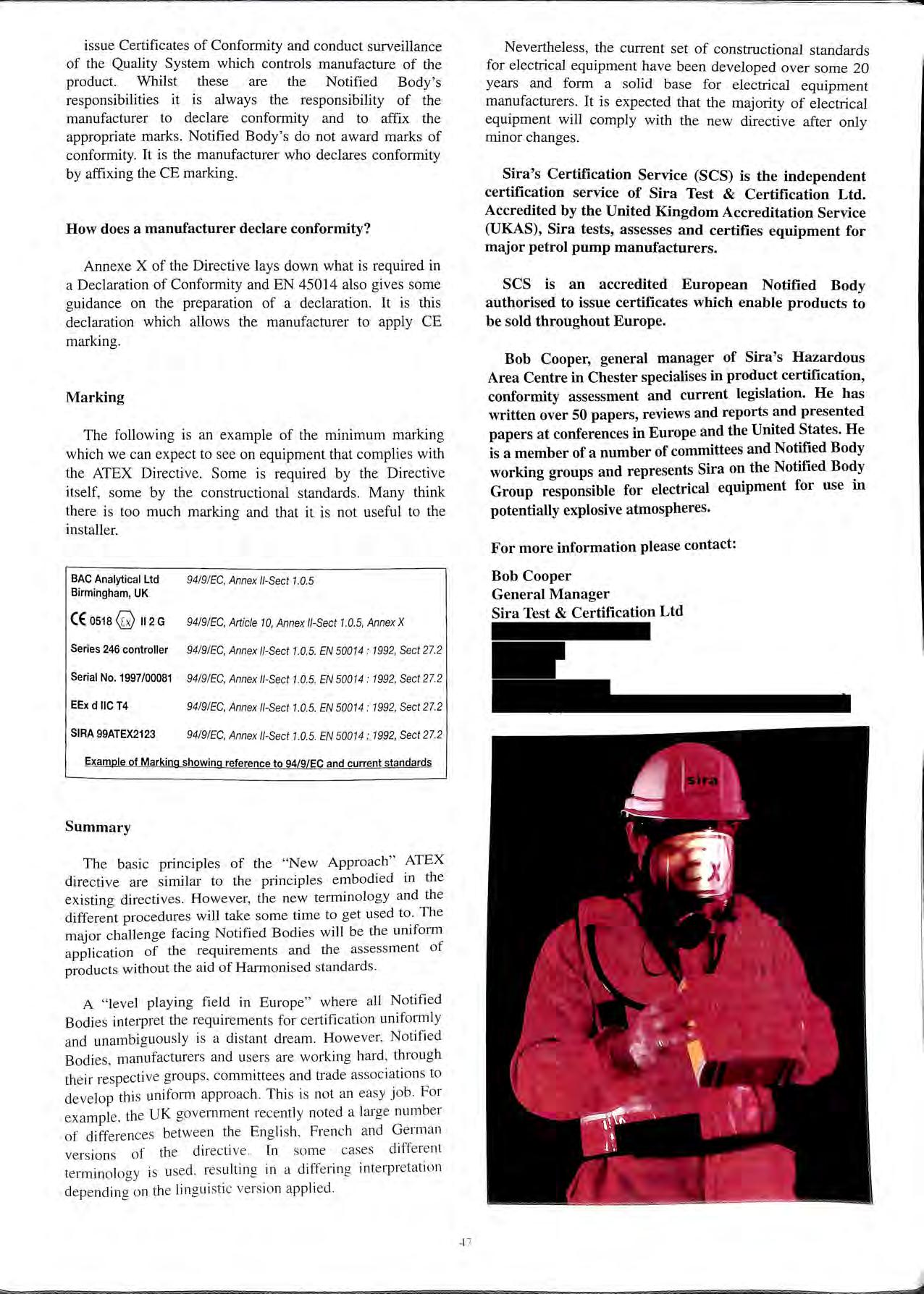
SIRA 99ATEX2123 9419/EC , Annex /I-S ect 1 0.5. EN 50014: 1992, Sect 27.2
Example of Marking showing reference to 94/9/EC and current standards
Summary
The basic ptinciples of the " New Approach " ATEX directive are similar to the principles embodi ed in the existing directives . Howe ver, the new term.inolog y and th e different procedures will take some time to get used W. Th e m ajor challenge facing Notified Bodies will be the umform appli cation of the requirem e nts and the ass e ssment of products without the aid of Harmoni sed standards.
A " level playing fi eld in Europ e" w here all Notified Bodi es interpret the require me nt s for ce 11ifi cati on uni fo rml y and un a mbiguou sly is a di stant dream. However, Notifi e d Bodie s, manufacture rs and users are workin g hard , thro ug h th e ir re s pec ti ve group s, committees and trade assoc iati o ns to deve lop thi s uni fo 1m appro ac h. Thi s is no t an easy j o b. Fo r exa mpl e , th e U K gove rnm ent rece ntl y noted a large numb er of differe nce s betwee n th e Eng li s h, Fre nc h and G e rman ver sio ns of th e direc ti ve . In so me cas es diffe re nt te rmin o logy is use d res ul tin g in a di ffe rin g in te rpreta ti o n de pendin g o n the lin g ui sti c ve rs io n appli ed
Nevertheless , the current set of constructional standards for electrical equipment have been developed over some 20 years and form a solid base for electrical equipment manufacturers. It is expected that the majority of electrical equipment will comply with the new directive after only minor changes.
Sira's Certification Service (SCS) is the independent certification service of Sira Test & Certification Ltd. Accredited by the United Kingdom Accreditation Service (UKAS), Sira tests, assesses and certifies equipment for major petrol pump manufacturers.
SCS is an accredited European Notified Body authorised to issue certificates which enable products to be sold throughout Europe.
Bob Cooper, general manager of Sira's Hazardous Area Centre in Chester specialises in product certification, conformity assessment and current legislation. He has written over 50 papers, reviews and reports and presented papers at conferences in Europe and the United States. He is a member of a number of committees and Notified Body working groups and represents Sira on the Notified Body Group responsible for electrical equipment for use in potentially explosive atmospheres.
For more information please contact:
Bob Cooper General Manager
Sira Test & Certification Ltd
4 7
CATEGORISATION OF PETROL DISPENSERS UNDERATEX
By John Hazeldean HM Principal Specialist Inspector
This paper provides the HSE view with respect to the equipment categorisation for petrol dispensers under the ATEX Directive.
Background
1. Under the ATEX Directive (94/9/EC) manufacturers will have duties to design and manufacture equipment to meet relevant essential health and safety requirements that take into account faults and misuse as well as normal operation. These requirements include measures:
• to prevent, if possible, the equipment from forming explosive atmospheres
• to prevent the ignition of explosive atmospheres from electrical and non-electrical sources
• to halt or limit the range of any residual dangerous explosion flames and pressures to a safe level.
2. The Manufacturer will also have to demonstrate conformity with these requirements by various testing and auditing arrangements depending on the particular equipment group and category for which it is designed.
Issues
3. Although the manufacturer will mark his equipment with the relevant equipment group and category it will be for the user to decide which particular equipment group and category he requires depending on the particular circumstances in which he intends to use it. In this decision making process the user, in this case the petrol filling station operator, will need to consider the risks arising from the use of the dispenser and be able to justify his conclusions to the relevant health and safety enforcing authority.
4. HSE seek to provide sound legal and technical advice to the numerous enforcing authorities for petrol filling stations in order to obtain a common position with respect to enforcement and safety.
5. Petrol dispensers present a number of issues under ATEX. Firstly they are potential ignition sources and secondly not only are they used in potentially explosive atmospheres created by both the dispenser itself and other forecourt equipment they generate .flammable atmospheres within the dispenser housmg. The categorisation procedure for a complete '.s not normally related to any hazardous w1thm equipment but on the hazardous areas that anse around 1t. The hazardous atmospheres within the pump are relevant to the pump manufacturer in that they will need to select and properly install components that are suitable for those atinosphercs. It could. however. be argued that because the hazardous atmospheres in the dispenser are not isolated from
those outside there needs to be an assessment for those components in order to minimise the possibility of a fire or explosion developing within the dispenser and then escalating to the outside.
6. As the conditions of use for petrol dispensers changes very little between different petrol stations we would expect some universal agreement on their categorisation particularly as petrol dispensers are regularly moved between sites. Slight variations in categorisation may occur but these will be only in abnormal or unusual circumstances. Such circumstances may include, for example, installation in a very windy and exposed position or within a building as may be the case in a car assembly factory.
Conclusions
7. The consensus of opinion within HSE is that we would recommend to the dispenser manufacturer and the DTI that new petrol pumps are defined as group II category 2 equipment under ATEX.
8. DTI are the lead body in UK who are seeking to obtain common agreement at the ATEX Standing Committee in Europe on issues arising from the Directive, and in reaching this concensus we take into account:
• The criteria, specified in the ATEX Directive, for determining the classification of equipment categories. ATEX states "Group II category 2 comprises equipment designed to be capable of functioning in conformity with the operational parameters established by the manufacturer and of ensuring a high level of protection. Equipment in this category is intended for use in areas in which explosive atmospheres caused by gases, vapours, mists or air/dust mixtures are likely to occur."
• The hazardous areas around a dispenser include zone 0, zone I and zone 2 areas. The hydraulic housing of the dispenser is surrounded by a zone 2 area with a zone I area all around up to a height of 250mm. There are also zone I areas at the nozzle housing and at the vent from the air separator. Small zone O areas exist within the nozzle spout housing and within the opening of the vent pipe from the air separator. Even if the vent outlet is within the dispenser housing, as opposed to discharging directly to the outside, the potentially for explosive atmospheres to exist outside hydraulic housing would still occur.
• A fire or explosion within the hydraulic housing would not be contained but would be able to communicate to the hazardous areas outside of the pump. Inadequate controls on the dispenser could also allow an explosion within the dispenser to spread to other connected equipment such as the vehicle fuel tank and the underground storage tank
• Dispensers are used by untrained and largely unsupervised members of the public who may not appreciate the hazards from petrol. Normal use will generate an explosive atmosphere around the nozzle and because of the flexibility of the hose this atmosphere could exist anywhere within the reach of the hose.
• It is foreseeable that use and misuse can give rise to spills of petrol around the dispenser.
• Tolerability of risk. Those likely to be affected by any hazards arising from dispensers are generally members of the public and this could include children as occupants of a vehicle. It is generally accepted that higher levels of control are required to protect members of the public
from risks arising from work activities than for employees. This is especially true for hazards involving fire and explosions which are particularly dreaded by people.
• Whenever explosive atmospheres arise people will be near to the dispenser and exposed to the potential fire and explosion hazards.
• Past experience within the UK has found it advisable to have petrol dispensers tested by a notified body in order to demonstrate that they meet the required standards of safety. There is no evidence to suggest these requirements should change.
UK BAN ON THE SALE OF LEADED PETROL
The Government intends to ban the general sale of leaded petrol in the UK from 1 January 2000 under the EU Directive 98/70/EC. DETR anticipate that the necessary revision to the Motor Fuels (Composition and Content) Regulations 1994 will be laid before Parliament before the summer recess. The new Regulations will also control the sale of the small amount of leaded petrol which will continue to be sold under a special derogation.
Background
In order to comply with the general ban on leaded petrol the UK retail petrol industry will phase out leaded petrol in the 4th quarter of this year. At the same time an alternative will be introduced to cater for the millions of motorists affected by the ban. The alternative will either be a lead replacement petrol pre-blended with anti-wear additives or bottles of anti-wear additives that the motorist can add to the petrol in the fuel tank. Both methods are in use in Europe but most countries have opted for pre-blended lead replacement petrol. The solution to be adopted in the UK is a commercial decision for each company.
In terms of the consumer the petrol retailing industry wants to minimise confusion by continuing the current practice with leaded petrol ie selling lead replacement petrol through wide diameter nozzles with red shrouds. Signage at the service station and on the pump combined with company literature will advise the motorist of the change. (Note the small amount of leaded petrol marketed for "characteristic cars" post 2000 may also be sold through similar pumps.)
Effect on the industry
The general ban will cause a number of major. sh011 term operational problems for the industry. These are:-
1. Lead Content
The current Motor Fuel Regulations only allow petrol to be sold if it has between 0.05 and 0.15 g/litre or less than 0.013 g/litre of lead. The complete ban on leaded petrol requires the UK production of leaded petrol to stop well before 1 January 2000 so that the distribution system can be flushed out. Unfortunately the need to flush the whole system at once might result in lead replacement petrol (LRP) containing more than 0.013 g/litre of lead being distributed in the early stages. LRP would only be dispensed wide diameter nozzles, as leaded petrol is now, so converters would not be affected. The LRP would contam anti-wear additives. Fuel suppliers will of course keep the changeover period as short as possible.
The only alternative would necessitate the uplift and collection of the tank bottom contents. This would be a potential source of environmental and safety risk and cause massive disruption to the petrol distribution system.
2. Labelling
The grades of petrol being sold on a service station are indicated on the pole sign and on individual pumps. The rapid conversion programme will make it difficult to ensure that all signs on every site are changed at once. There may therefore be a period when temporary labelling is used to advise the consumer that an alternative grade is being supplied in place of leaded petrol.
3. Changeover Period
CmTently the envisaged changeover period where some flexibility is required is from 1 October 1999 to 31 December 1999. UKPIA, AUKOI and the PRA are discussing cooperation with LACOTS to ensure a smooth transition in the switch from leaded petrol.
.+<J
Defining the prob lem and controlling development costs
Given the general complexity of the shallow geological environment, si te observation of where a spilled product has entered into the ground, may then be followed by the thou g ht " I wonder where it has gone exactly?" This may be crucial on more than one count, where chemical attack on underground serv ices is a pos sibility via migration, through to environmental liabihty Checking potential " un seen" contaminant so urce s, in particular underground storage tanks may already be on the environmental agenda. Understanding contamination (in its three dimensions) can prevent further mjgration and can be used to dev elop an appropriate monitorin g and remediation pro gramme
Q uantifyin g contamination within a given area is often based up o n little dat a from a minimal number of boreholes, trial pits or extrapolatin g from surfac e so il vapour meas urements Thj s may be sufficient in many cases, but actual boundarie s , both latera ll y and at sha llow depth are ge nera ll y ill defined , often wit h extrapolati on of a boundary taken at some arb itrary point between two sa mplin g points. T he probl e m to be so lve d ma y therefore appear far worse than it act uall y is due to lac k of knowledge These factor s may remain with li tt le further reso lu tion at the site remed iation stage w he n whol e areas of potentiall y co nta min ated so i1 may be removed or treated , far more th an ma y be neces sa ry ( i f needed a t a ll )
A recent advance in non-intrusive technology now enables a whole area to be scanned (particularly for hydrocarbons) in detail. Its comprehensive coverage provides a greater certainty of detecting any "hot spots" of contamination, compared to boreholes a lone. Its nonintrusive nature has further advantages in its ability to rapidly collect data, whilst mirumising any disruption to operational sites.
The three dimensional mapping of contamination is ac hieved by undertaking field surveys using Ground Penetrating Radar (GPR). This is an established method to locate underground tanks, pipes and geological information
The ability of GPR to detect contamination is a fairly recent achievement, but now has an established track record of over 250 surveys. Thi s has been poss ible through the recognition of particular contamination signatures appearing in the field data and through the development of computer software (Enviscan) to enable these zones to be accurately defi ned These surve ys have to date concentrated on hydro carbon contamination and have been carried out on petrol stations. airfield s, brownfield sites, fac tori es, o il refineri es and chemical plants . Surveys mapping ot her types of organic contamination ha ve also been carried out. The GPR data is quantitative through correlati o n with a minimal numb e r of laboratory analy ses of so il o r g ro und wate r sa mpl es
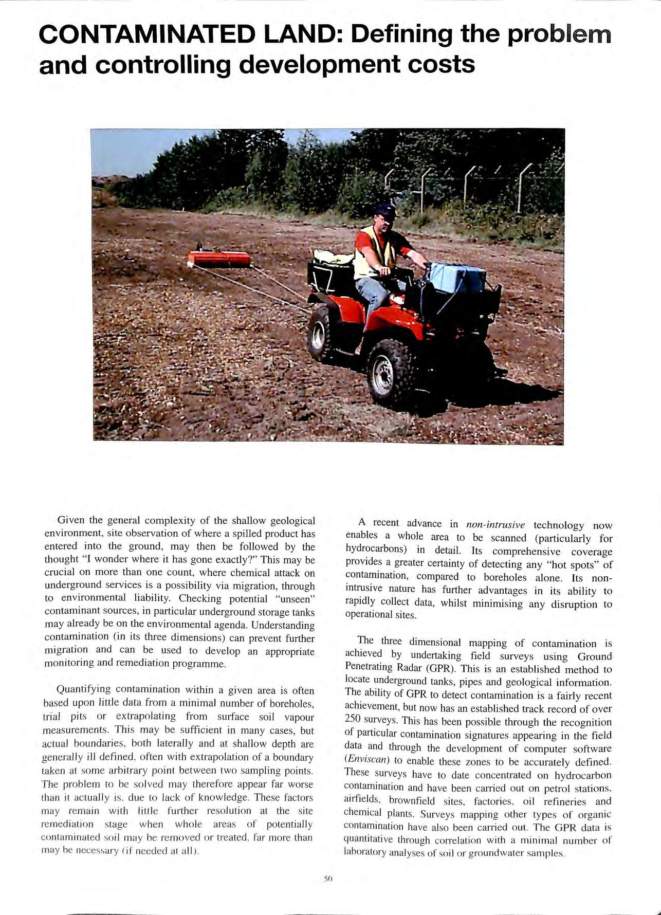
CONTAMINATED LAND:
50
Enviscan provides a powerful visual analysis of location and concentration of hydrocarbons in the soils beneath a survey area. The various colours shown in the example of a petrol station recently surveyed represent this threedimensional variation in concentration Red equates to the highest relative concentrations, through orange, yellows, greens and finally blues, equating to background concentrations. Enviscan is exclusive to Technos in the UK and Eire.
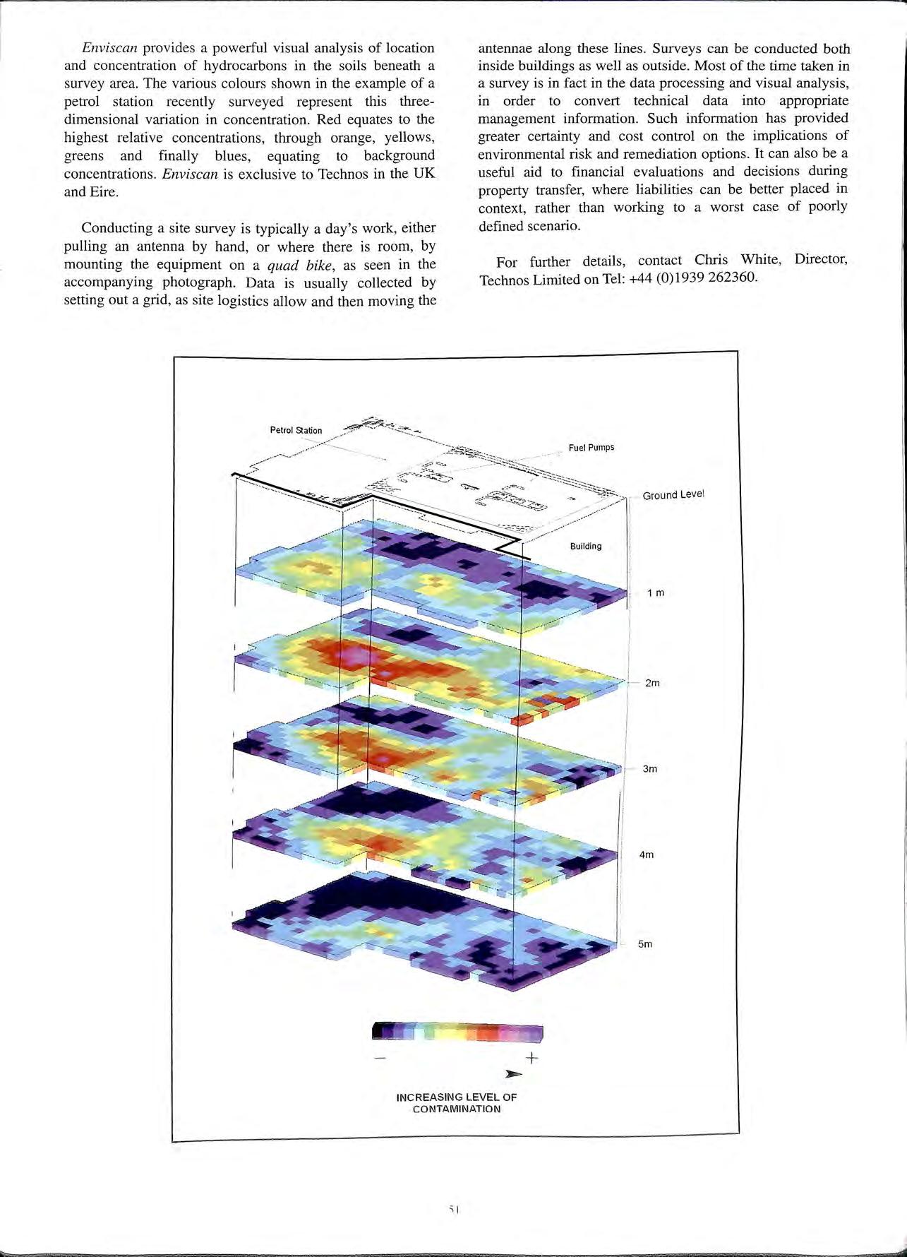
Conducting a site survey is typically a day's work, either pulling an antenna by hand, or where there is room, by mounting the equipment on a quad bike, as seen in the accompanying photograph. Data is usually collected by setting out a grid, as site logistics allow and then moving the
antennae along these lines. Surveys can be conducted both inside buildings as well as outside. Most of the time taken in a survey is in fact in the data processing and visual analysis, in order to convert technical data into appropriate management information. Such information has provided greater certainty and cost control on the implications of environmental risk and remediation options. It can also be a useful aid to financial evaluations and decisions during property transfer, where liabilities can be better placed in context, rather than working to a worst case of poorly defined scenario.
For further details, contact Chris White, Director, Technos Limited on Tel: +44 (0)1939 262360.
-.:: ;'-'=t,
Petrol Station
2m 3m 4m 5m + INCREASING
_,- Fuel Pumps Ground Level Building 1 m
LEVEL OF CONTAMINATION
VAPOUR RECOVERY PUMPS
By Gordon Ward
Fenner Fluid Power first became involved in Stage II Vapour recovery when the company purchased Charles S Madan in 1990.
Charles S Madan had developed a vacuum pump suitable for pumping fuel vapour. At the time of purchase the pump had acquired all the necessary legislation and safety certificates and was being introduced to the market place.
The original specification that Charles S Madan had worked to was brief and basically covered flows and pressures. The medium being pumped was petrol fuel vapour and therefore the pump had to meet the necessary safety requirements such as Physikalisch-Technische Bundesanstalt (PTB).
Shortly after the introduction of the pump Fenner Fluid Power's quality system registered a high number of warranty returns due to pump seizure. It soon came to light that the fuel dispensing industry had failed to mention the possibility of liquid entering the system. Pump designed for vapour is totally different to a pump designed to handle liquid. Vapour is a compressible medium and fuel is virtually incompressible and therefore obviously affects the design of the pump.
Fenner Fluid Power's design engineers therefore hurriedly went to work to find a solution to the obvious problem, that of liquid handling.
A solution was found whereby the pump could be modified to handle a small amount of liquid and although the Sales Department made many enquiries no one in the industry was prepared to say exactly how much liquid could get into the system. In fact no one would even admit that liquid got into the system.
The modified pump was introduced into the market and product numbers damaged by fuel dropped drastically. The Engineering Department had proved that when liquid is suddenly introduced into a pump design for vapour internal pressures increase drastically to the point of failure. The rotor shaft was extended to include a back bearing to prevent this deflection. Galleries were introduced into the pump to allow the liquid to pass through it. It was these early designs of pump in Europe and the lack of knowledge of the market that caused many of the pumps to fail, not only the Madan pump but their competitors too.
Fenner Fluid Power decided it was time to go back to the drawing board and totally redesign the pump with the knowledge they had learned from the market place. A survey was carried out to find out what the industry expected of Stage fI Vapour recovery Pumps now and in the future. From this survey a number of surprising points came to light as follows:-
1. The noise level of the pump was very important as many fuel stations work 24-hours a day and are in close proximity to residential areas. Whilst the noise may not be noticed during a normal working day with heavy traffic, at 3 a.m. in the morning a quiet pump became an important factor.
2. Dispenser manufacturing is a global industry and many of the major players manufacture both in Europe and America. It was therefore obvious that a worldwide pump design would have to meet knot only European standards (PTB) but also the American standards (UL).
3. The pump must be able to pump liquid continuously and then return to vapour without damage to the operation of the pump.
4. The pump must be suitable for either pulley drive or directly coupled to an electric motor but again bearing in mind the safety regulations on both sides of the Atlantic.
5. Up to the point of the survey all multi-purpose dispensers (MPD) that had been fitted with the Stage II Vapour Recovery had one pump for each side of the dispenser. The industry could see an advantage in having one pump within the dispenser capable of handling the vapours from both sides simultaneously, providing a control system could be obtained to maintain it within certification limits.
6. If the pump was to be marketable on both sides of the Atlantic consideration would have to be taken to the motor speeds when close coupling to an electric motor i.e. 1750 rpm in the USA and I 450 rpm in Europe. The different thread connections would also have to be taken into consideration on the inlet and outlet of the pump.
7. Oil companies and therefore dispenser manufacturers are asking for 2 years plus warranty periods for the system to remain within legislation.
8. The Sales Department required all of the above features building into one pump for the World Market.
It took the Research & Development some I 8-months to meet the above specification. With one pump design the Engineering Department have been able to meet all of the requirements. The four pumps designated, G50, G56. G I 00 and G 112, the only variable being the length of rotor.
GSO
This pump was designed to run at 1750 rpm and recover vapour from one nozzle. Minimum 45 l/min.
G56
This was designed to run at 1450 rpm and recover vapour from one nozzle. Minimum 45 l/min.
This pump was designed to run at 1750 rpm and recover vapour from two nozzles simultaneously. Minimum 90 l/min.
G112
This pump again recovered vapour from two nozzles simultaneously while running at 1450 rpm. Minimum 90 l/min.
These four models met the requirements of PTB safety certificate in Europe and UL requirements in the USA. They are suitable for close coupling to motors running at either 1450 rpm or 1750 rpm and could recover the vapour from one nozzle, or from two nozzles simultaneously. All of the pumps could either be pulley driven directly coupled to a motor and more importantly did not fail when liquid was introduced into the pump.
The G56 and the G112 were both given PTB approval and passed the TUY system tests and were introduced to the market place. The pump was launched at exhibitions and demonstrations were given in its liquid handling capabilities and its versatility on mounting in any position driven by pulley or motor showed it was suitable for a world market.
The companies that took up the new Fenner pump were not disappointed as the pump met all expectations and product returns were virtually zero. Of the few that were returned the pumps were found to have black sooty deposits in them. The initial concern was that this black deposit was coming from the carbon blades within the pump. Analysis showed that whilst the black deposit was carbon it was of a totally different material to that of carbon blades and was in actual fact coming out of the fuel and even then the number of cases was very small.
In many systems today a Stage II Vapour Recovery Pump on the left side of an MPD runs on full vacuum when only the right side is dispensing fuel i.e. they use one common drive for the two pumps which works well but generates heat. With the G 112 pump if either or both sides of the MPD are in use you always have vapour passing through the pump which in tum keeps the pump cooler and less risk of the sooty carbon deposit.
Sales figures of the G56 rose rapidly. The Sales Department still had a hard job ahead of them as a number of companies had started to believe that the vane principal of vacuum pumps was unsuitable for Stage II Vapour Recovery and these companies turned to the recently introduced piston design of pump. They believed, wrongly, that the piston design did not fail when liquid entered the system, even though many of the piston pumps on the market were known to be more noisy than the vane type pump, physically larger and very restrictive in the location and mounting orientation of the pump.
During the design of the Fenner pump they had considered manufacturing a piston unit but found that the piston had many limitations including the noise level of the pump but also the physical size 1f 1t was to meet BASEEFA and PAS0'.22 requirements.
Sales of the G56 continued to do well but the sales of the G 112 had only reached 1/20th of that of the G56 and yet this pump offered a huge cost saving to the industry and a space saving within the dispenser. There was one drawback no one had developed a suitable control system for this particular pump. A control circuit was required where the vacuum from one side of the dispenser did not affect the vacuum from the opposite side when both were running simultaneously.
Fenners Research & Development department turned their attention to looking at a control system which would control vapour into th G 112 pump and achieve what the company still believed that the fuel dispensing industry required, one pump in a dispenser.
The ideal control circuit accepted by most of the industry was called the 'feed back' system whereby the vapour recovered was actually measured and compared with the fuel being dispensed and the valve adjusted accordingly. This ensured that both the vapour recovered and the fuel dispensed remained exactly equal by volume. This principal of Stage II Vapour recovery system has been known for some time and accepted as the correct way to do it. However, the stumbling block had always been to obtain a cost effective, fast response flow meter that would meet the industries requirements.
Fenner Fluid Power tested many flow meters and they all failed for various reasons, but most commonly because they did not have the response time to changes in flow that were required for the industry. Early in 1997 Fenner Fluid Power was asked to test a Fleisch tube. This is basically a flow meter that has been well established in the medical industry for many years, tried, proved and tested. Fenner were surprised it fitted the requirements of the mdustry perfectly. It had no moving parts, was unaffected when liquid entered the system, it had a complete linear and had a very fast response to changes in flows and rt . h · t requr"rements of PTB, would also easrly pass t e stnngen BASEEFA and other safety bodies.
t m far exceeded
The accuracy of the Fenner sys e . d. d th t you must contmually expectations. Leg1slat10n 1ctate a . . . sm f th fuel being dispensed by recover vapour w1thm -10 o e volume and yet Fenner Fluid Power had. a easily controlled it to within l % and most umes withm /_to l/4 per cent. The hard work that the Engineering Department was expending was beginning to pay off.
A world-wide patent was obtained for the use of the Fleisch tube within Stage II Vapour Recovery systems.
Development work continued in earnest on the system, but at the same time the UK was slowly movmg towards legislation. Up until then the G56 and the G 12 pump had been accepted in Europe with a PTB safety ce1tificate. If Fenner Fluid Power wanted to get into the UK market they knew they would have to meet BASEEFA requirements which is a safety requirement for components installed in a dispenser within the UK. Fenner also knew that this safety requirement was of a far higher standard than that of PTB.
GlOO
'i.,
The Engineering Department were asked to continue the work on the control circuit but at the same time ensure that the pump would meet BASEEFA requirements and also PAS 022. There was no doubt the pump would require some changes in dimensions to meet these requirements including a new pedestal and an increase in the external dimensions of the pump by some 3rnm. This slowed down what had become known as the Fenner EVR system (Enhanced Vapour Recovery). By mid 1998 both the G56 and Gll2 pumps were submitted to BASEEFA for approval. At the same time Fenner submitted the new control system to BASEEFA for approval.
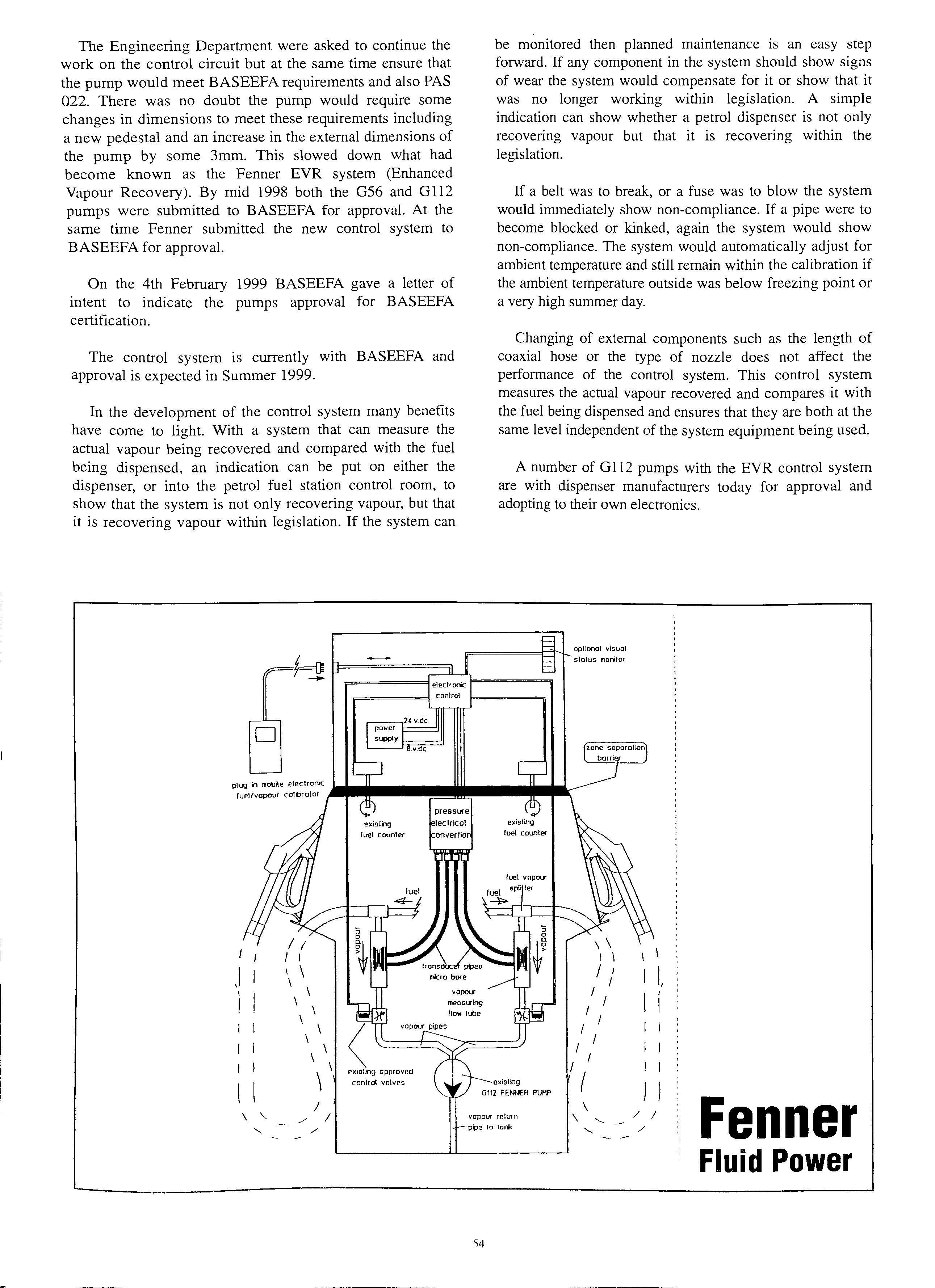
On the 4th February 1999 BASEEFA gave a letter of intent to indicate the pumps approval for BASEEFA certification.
The control system is currently with BASEEFA and approval is expected in Summer 1999.
In the development of the control system many benefits have come to light. With a system that can measure the actual vapour being recovered and compared with the fuel being dispensed, an indication can be put on either the dispenser, or into the petrol fuel station control room, to show that the system is not only recovering vapour, but that it is recovering vapour within legislation. If the system can
be monitored then planned maintenance is an easy step forward. If any component in the system should show signs of wear the system would compensate for it or show that it was no longer working within legislation. A simple indication can show whether a petrol dispenser is not only recovering vapour but that it is recovering within the legislation.
If a belt was to break, or a fuse was to blow the system would immediately show non-compliance. If a pipe were to become blocked or kinked, again the system would show non-compliance. The system would automatically adjust for ambient temperature and still remain within the calibration if the ambient temperature outside was below freezing point or a very high summer day.
Changing of external components such as the length of coaxial hose or the type of nozzle does not affect the performance of the control system. This control system measures the actual vapour recovered and compares it with the fuel being dispensed and ensures that they are both at the same level independent of the system equipment being used.
A number of GI 12 pumps with the EVR control system are with dispenser manufacturers today for approval and adopting to their own electronics.
D J I I I I I \ \ \ exi9lilg fuel counler
opliooal visual slolus 1110111tor \ \ I I I I I I I, \ \ meac1Xlng I I flow lube \ \ vapour pipes I I \ \ I I I \ \ I l l conlrol valve!i exi9ling ( I I G1\l FENNER PUMP I \ Fenner \ " ./ I vapour relurn \ ' / I ' / pf.>c to lank '-. / Fluid Power 'i4
THE ABOVE GROUND SOLUTION TO UNDERGROUND PROBLEMS
By M. Burgess
Nationwide interest in the preservation of our environment has prompted all levels of government to issue strict guidelines for the protection of our environment. As a result owners of petrol and diesel installations now face catastrophic clean up costs if a contamination problem arises.
Councils are now leading the enforcement of these new guidelines particularly in respect of contamination of our waterways, where most petrol and diesel leaks eventually find their way to. As a result owners/operators are now faced with expensive upgrades, testing, monitoring equipment and pollution liability insurance to comply with these requirements. In the event of a leak in a diesel or petrol tank below ground the actual cost for soil and ground water clean up can be catastrophic. The installation costs of new below ground tanks now have escalated due to the requirement of double skin tanks, leak detection of the same observation wells around the tank area. These tanks will also require monitoring equipment to test for potential leakage of tanks and tank contents to ensure that discrepancy is always below 5%. Anything above .5% must be reported immediately. All tanks below ground are now to be double skinned and leak detected. All petrol tanks are now to have Stage l B vapour recovery fitted.
The first of these new guidelines which is now being enforced in 1999 is Stage l B Vapour Recovery where the delivery tanker must connect to the tank vent and recover the vapour while bunkering tanks. This involves costly modification to existing installations. The existing vents now have to have fitted a 3" vapour recovery line from vent stack to offset fill point complete with cross contamination valves fitted if multi-tanks, flame arrester unit on vent line at offset fill point, offset vent connection preferably camlock couplings, all necessary warning notices i.e. warning connect vapour recovery before off loading and also inside tank manhole a warning that this tank is manifolded for vapour recovery. Below ground tanks must now be regularly tested for tank integrity. This includes all pipelines and below ground equipment. Furthermore the existing hydrostatic gauge fitted to many installations is no longer of any use so these gauges must be changed on fitting vapour recovery.
County Councils are leading the enf?rcement of these regulations and Trading Standards and Fire and_ Rescue_ are very much involved in inspecting fuel mstallat10ns particularly in respect to below ground storage.
Historically the storage of petrol up to 1998 on sites other
than terminals, has always been below ground in the UK. The US, Canada and many other countries for the last I O years have preferred above ground storage of these fuels because of the potential ground and water contamination and the environment effect of this contamination. If ground is contaminated by fuel or any other matter it is no longer sufficient to remove the source but the contamination must also be removed. No-one knows the cost until excavation is in progress and then only then when all is removed it has to be disposed of to a licensed toxic disposal site. All these costs are the responsibility of the owner/operator and liability insurance companies are very aware of this problem.
The UK has now decided to follow the US and other countries and allow the storage of these fuels above ground as a potential environmental problem can be detected before it arises (if you can see it you can avoid it). If it is below ground it can be a number of years before it can be detected and then it is too late as it becomes an expensive clean up operation
To this end Mid Bucks Engineering have introduced into this country above ground petrol storage tanks designed and patented by ConVault Ltd of the USA. The ConVault meets government, environmental and fire safety regulatwns and meets all safety requirements for primary and secondary containment leak monitoring, spill containment and overfill protection.
The above ground petrol storage tank has been approved ffi · 1 · over 20 OOO global by environmental protect10n o icia s m • sites, including all 50 states of the USA and all provmces m Canada, without a single system failure. It has a number of advantages over below ground tanks it can be seen at all times it needs no expensive excavation or ground work and it is p'ortable and can be moved from site to site. !t has engineered for safety as Con Vault tanks are engmeered _tor tightness integrity, utilising patented manufacturmg procedures. The result is a seamless six-inch thick_ vault which oives thermal protection. mm1m1smg temperature for flammable and combustible liquids stored in excessively hot or cold environments. The system contains no cold joints or heat transfer points on the bottom or sides. The monolithic shell also provides ballistic and vehicle impact protection for secondary as well as primary containment.
For further assistance in this matter contact Mid Bucks Enginee1ing Ltd Tel: 01296 422039. Fax: 01296 or visit our website at www.mid-bucks.com.
HSE ADVISES ON SIDP AND SHORE TRANSFERS OF DANGEROUS SUBSTANCES
Advice on the safe transfer of dangerous liquids and gases between ship and shore is given in a new guidance book published by the Health and Safety Executive (HSE).
' The bulk transfer of hazardous substances between ship and shore' provides information on the fire, explosion , toxic and environmental hazards associated with such transfer operations and is aimed at harbour or port authorities , and owners, operators and users of berths.
The objectives are to:
• help in the assessment of the risks from the transfer of dangerous liquids and gases between ship and shore, and
advice on how to control these risks:
• increase the awarene ss of the potential fire, explosion, toxic and environmental hazards associated with the transfer of dangerous liquids and gases between ship and shore ;
• advice on safe management procedures and appropriate precautions to prevent or reduce injuries and damage caused to property or the environment associated with such operations;
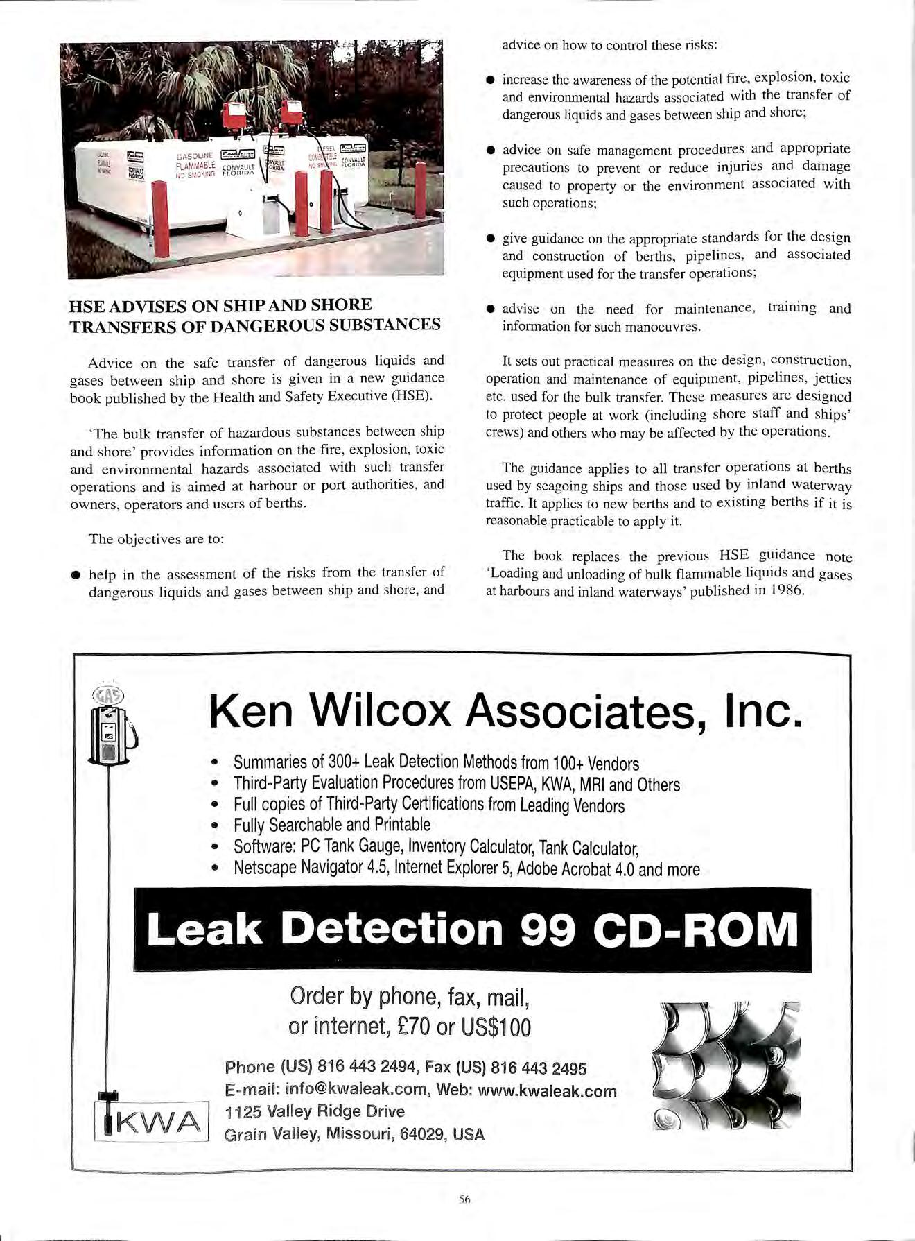
• give guidance on the appropriate standards for the design and construction of berths, pipelines , and associated equipment used for the transfer operations;
• advise on the need for maintenance, training and information for such manoeuvres
It sets out practical measures on the design, construction, operation and maintenance of equipment, pipelines, jetties etc. used for the bulk transfer. These measures are designed to protect people at work (including shore staff and ships' crews) and others who may be affected by the operations.
The guidance applies to all transfer operations at berths used by seagoing ships and those used by inland waterway traffic. It applies to new berths and to existing berths if it is reasonable practicable to apply it.
The book replaces the previous HSE guidance note 'Loading and unloading of bulk flammable liquids and gases at harbours and inland waterways ' published in 1986.
Ken Wilcox Associates, Inc. • Summaries of 300+ Leak Detection Methods from 100+ Vendors • Third-Party Evaluation Procedures from USEPA, KWA, MRI and Others • Full copies of Third-Party Certifications from Leading Vendors • Fully Searchable and Printable • Software: PC Tank Gauge, Inventory Calculator, Tank Calculator, • Netscape Navigator 4.5, Internet Explorer 5, Adobe Acrobat 4.0 and more Order by phone, fax, mail, or in ternet, £70 or US$100 Ph o ne {U S) 8i 6 443 2494, Fax (U S) 816 443 2495 E- mail : info @kwa leak .co m, Web: www.kwaleak.com 1125 Va lley Rid ge Dri ve Grain Vall ey, Missou ri, 64029, USA 56
diesel nozzle
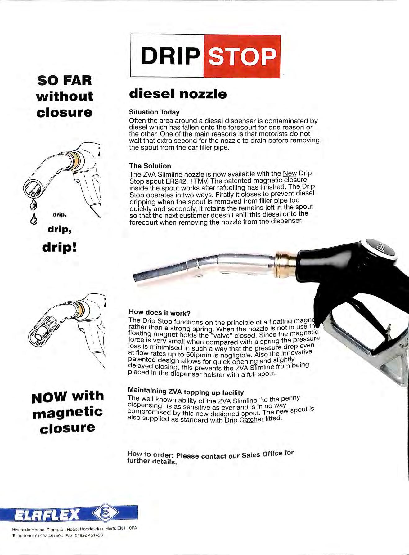
Situation Today
Often the area around a diesel dispenser is contaminated by diesel which has fallen onto the forecourt for one reason or the other One of the main reasons is that motorists do not wait that extra second for the nozzle to drain before removing the spout from the car filler pipe
The Solution
The Z.VA Sliml ine nozzle is now available with the New Drip Stop spout ER242 1TMV. The patented magnetic closure inside the spout works after refuelling has finished. The. Drip Stop operates in two ways Firstly it closes to prevent diesel dripping when the spout is removed from filler too quickly and secondly, it retains the remains left 1n the spout so that the next customer doesn't spill this dies_el onto the forecourt when removing the nozzle from the dispenser.
How does it work?
The Drip Stop functions on the principle of a floatin!;J rnagn than a strong spring. When the nozzle is not 1n use • magnet holds the "valve" closed. Since the magnetic force: is l?mall when compared with a spring the pressure loss is m1nim1sed in such a way that the pressure drop eyen at flow rates to 501pmin is negligible. Also innovative patented allows for quick opening and slightly closing, this prevents the Z.VA Slimline from being placed in the dispenser holster with a full spout.
Maintaining 'ZVA topping up facility known ability of the ZVA Slimline "to the penny is as sensitive as ever and is in no way ut is compromised by this new designed spout. The new spo also supplied as standard with Drip Catcher fitted.
How to order : Please contact our Sales Office for further details.
SO FAR without closure ' I • .,.._"'=_.,,___;- ..!\ \ drip, drip, drip! NOW with magnetic closure DRIP
STOP·
Riverside House , Plumpton Road , Hoddesdon , Herts EN 11 OPA Telephone: 01992 451494 Fax : 01992 451496
The I S PET SE System offers the total solution the industry has been asking for. Consider the credentials of NIPS Petrofuse and Fusamatic. • FULLY WELDED SYSTEM • CORROSION-RESISTANT • NON-PERMEABLE • NON-BRITTLE • TRACEABLE PIPE JOINTING • LOW COST • RIGID SYSTEM • DETECTABLE PIPELINE The product range consists of a range of pipe, fittings and tooling in the size range 50mm, 63mm, 90mm, 11 Omm The pipe outside diameters are based upon BS 5556 and ISO 161 /I. All of the pipe and fittings are black pigmented. Black has been carefully selected as it affords the best and most cost effective solution against environmental UV degradation, that can occur with polymers .The polymer has also been carefully selected to provide the 30 year design life required by the specifications of the industry fUSAMATUC c WORLD EADING AUTOMATIC ElECTROfUS UON SYSTEM

Tank G auging and Leak Detection \ I I ' 40 60 / -20 so100 a {II 8 HHL HL U. EURCGAUGB Lavol AJarms tk!udiu;& k: .. I TES T REFILL I LIQUID FILLED AND DRY AIR PRESSURE LEAK DETECTION SYSTEMS FOR STEEL OR GRP DOUBLE SKIN TANKS. LEAK DETECTION SYSTEMS FOR DOUBLE CONTAINMENT PIPES, ACCESS CHAMBERS AND PUMP ISLAND SUMPS. "PROLEVEL" TANK GAUGING SYSTEM FOR UP TO 16 TANKS. PC AND MODEM COMPATIBLE FOR LOCAL AND REMOTE MONITORING. "TANKGUARD" LOW COST ELECTRONIC TANK GAUGING SYSTEM. "TANKMATE 160' ' SELF-POWERED TANK GAUGE FOR DIESEL AND GAS OIL. INTERCEPTOR AND OIL SEPARATOR LEVEL ALARM SYSTEMS. BS EN ISO 9001 QUALITY ASSURANCE. ALL SYSTEMS MEET RELEVANT SAFETY STANDARDS. EEx ia /IC FOR ZONE O AND EEx ib /IC FOR ZONES 1 AND 2 . .... .. .... ..... . . ... . . .... . . .. . . ... ........... . .. . ..... Why not talk to the specia/ists:EUROGAUGE COMPANY LIMITED IMBERHORNE LANE, EAST GRINSTEAD , WEST SUSSEX RH191RF Tel: 01342 323641 Fax : 01342 315513 Qitality services for today 's forecoitrt HIGH QUALITY RE-I MAGING OF PUMPS, CANOPIES, SHOPS POLE SIGN ERECTION & MODIFICATION PLANNED IMAGE MAINTENANCE PROGRAMMES PUMPS & EQUIPMENT= HAULAGE, STORAGE & DISTRIBUTION Valley Road, Cinderford, Gloucester GL 14 2NY Telephone : 0594 826364 Fax: 0594 822807
Ii .J You deserve h the best, wysettle for less ... THE LEADER IN PETROLEUM TANK MANUFACTURE Including: • SUCTION PIPES e FILL PIPES e OVERFLOW PREVENTION • CHAMBERS • GROUND COVERS, and much more ...


Tiu Elatricnl MEMBER OF A.P.E.A Nationa lnspec!1on Council lor Eleclrica Installation Contract ng SPECIALIST ELECTRICAL ENGINEERS & CONTRACTORS TO THE PETROLEUM INDUSTRY Co 11tn1crors'tlrsocin rio11 • •111E111 REGISTERED MEMBER APPROVED CONTRACTOR • Closed-circuit TV e Fire Alarms & Emergency Lightning e Planned Maintenance • Inspection & Testing • Forecourt Earthing Systems HEAD OFFICE: PROJECT HOUSE• THE DRIVE• WORTHING• WEST SUSSEX• BN11 5LL TEL: 01903 700321 FAX: 01903 507498 BY TOTAL CONTAINMENT Low cost, f lexib le so lution s for all fuel pipework PU Rf l EIET FORECOURT • Most flexible pipework system • No underground joints • Suitable for alternative f u el s ' • Hig h flow rates ' • Competi t ive prices TOTAL CONTAINMENT 520 London Road, West Thurrock, Grays, Essex RM 20 3BE Tel: 01708 86393 1 Ext 219 Fax 01708 864 140 Sole UK PURFLEET FORECOURT SERVICES LID Distr ibutor
Since pioneering the conce canopy back in the early 60'?t of pre-erigineeree development has se th' s, continuous protection evolve form weather image projecting struct sophisticated ure that rt 1s today.
Over the years Conder h . philosophy to other f( as applied this same objective of improvin elements with the construction time Tug qualrty whilst reducing h ese now incl d h was enclosures fact u e s op and car assembly, pump islandory prepared for rapid site di sunrounds with t I era es and sumps and ba in egra fuel dispensing equipmentrners to guard vulnerable
In protecting the environ never faltered and · d ment, Conder's resolve has advanced range of emonstrated by the most with coalescing filte ght liquid separators, complete pollutant level I rs, automatic closures and chambers silt t arms. to this the GRP access refurbishn°i raps. an a first class repair and b tt ent service the forecourt couldn't be e er protected.
CONDER FORECOURTS ABBOTIS BARTO N HO USE W O RTHY RO AD WI N CHE STER HAMP SHI RE S0 23 7SH FAX 01 96 2 8 41
PETRO
Le ss co stly th a n total tank replacement
No need for site closure
Continuous vacuum tank monitoring means no more periodic tank testing
Can be used to make pe1forated tanks (within reason) as good as new
Ta nk modifications po ss ible
No need to survey tank prior to lining as if tank i s d a maged it can be rep aired
· -------------- · . --------------.
IN OLD TANKS? NEUTRATANK
RG15
RGS
INSTALLING NEW TA N KS ? THERMOTANK RG30
e Absorbs
e High
cohesion e Insulates e tanks >!' USEBACELHARDFOAM Don't slurry in a hurry - call now for a free estimate
FILLING
RG22 for permanent tank abandonment
for tank mothballing
for safer tank excavation • Lightweight and high loadbearing • No need to remove lids or de-gas tanks • Fast clean application
for backfilling tanks
hydrocarbons
rigidity and
+
+
+
+
+
+
+
+
+
+
+
LIVE PETROLEUM TANK CLEANING using fibre optic
system
4/5 Gough Square, London EC4A 3DE Tel : 0171 583 2007 Fax : 0171 583 2008
TANKLINE Line your tanks with double skin GRP and save money
Effectively provides new tanks without the expense and disruption of total tank replacement
No requirement for expen sive Civil Works
Much less disruption to site
Fast installation Usually less than one week
+
30 y e ar life e xp ec ta nc y
S ye ar wa rra nty on labour and material s
camera/pump
• Safe precision removal of water and sediment • No lid removal, minium disruption • National coverage , version for large storage tanks • Also suitable for Derv gas and chemical tanks • Guaranteed to remove water • Competitive prices
w .I RJ & NJ WJilLILJIAlViS JLTD WJ[JLILIAMS SO UlliJE ILID Building & Civil Engineering Contractors Main Contractors to the Petroleum Industry for over 2 5 years Design & Build/Tendered/Negotiated Management Car & Jet Wash Installations Tank Removal & Disposal Fuel Tank Installations to Quality BS EN ISO 9002 : 1994 Area of Operation Safety Procedures Client Driven RJ & NJ Williams Limited Tel: 01752 201300 Fax: 01752 201299 Williams Southern Limited Tel: 01635 871828 Fax: 01635 871784 D T I E INSTITUTE OI l'l;rJIOl.l:tlM SAFE, AUTOMATIC I OCK RELEASE Just one of the benefits of the new ACIF ER Just one item in our product Range Vapour Recovery, Valves & Fittings, Manholes & Covers, Pipework, Spill Containers, Tank Truck, Nozzles, Gauges. The EBW Group Worldwide, Partners in Technology PO Box 5499, Wigston, Leicester, LE1 8 2ZE, Tel + 44 (0) 116 277 2700. Fax +44 (0) 116 277 29 paulch awner@ebw-apt.co uk THE FASTEST WAY TO :• Put 2" ,3" & 4" threaded entries into tank lids • Remove drop tubes • Install & supply OPD's (including 4" steel tubes) • Remove any existing sockets ---· II Safe accepted by HSE & all appropriate safety authorities • Quick • Cost effective IT MAKIES GOOD SENSE TO USE BORTIEC Ltd Hudson Hill , Hedingham Ro a d,Wet hersfie ld , Brain tree , Esse x CM7 4EH Tel (013 7 1) 850921 Fa x (0 1371) 850719
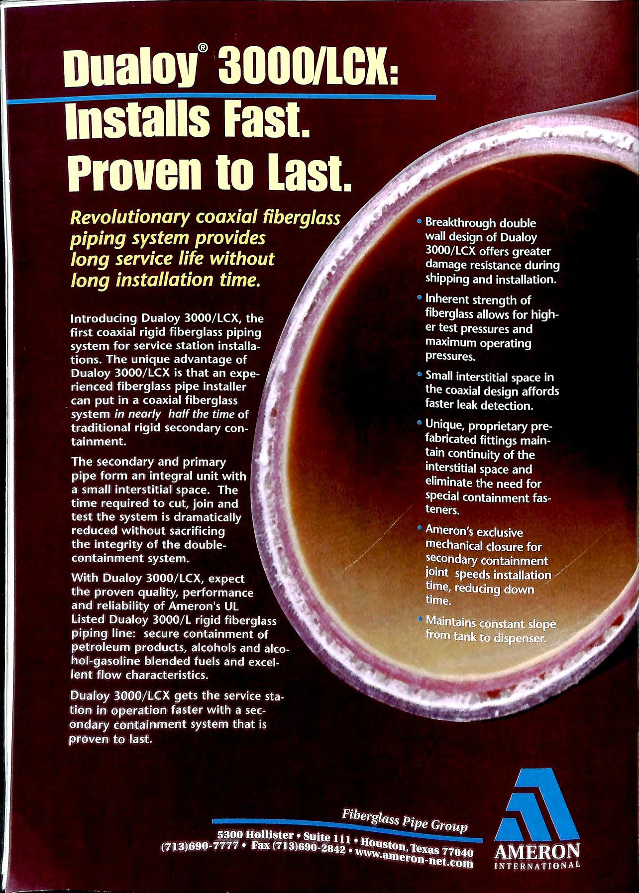
I L Environmental Engineering & Applied Science Extensive experience in undertaking specialist contaminated land remediation in the UK and Europe provides clients with tried and tested methods , applied by specialist staff, for dealing with polluted land and groundwater • Site assessment on petroleum retail sites and industrial premises • Fully costed remedial design proposals • Execution of remedial works with minimum disruption • Confidential prompt and professional service SPECIALISTS IN CONTAMINATED LAND CONTRACTING Telluric Ltd, Meandros House , 54A Bute Street, Cardiff Bay , CF1 6AF Tel: 01222 303010 Fax: 01222 303011 Toureen (Plant) Ltd. CIVIL ENGINEERING & DEMOLITION CONTRACTORS SPECIALISTS IN DEMOLITION AND DECOMMISSIONING OF PETROL STATIONS • • • • • Tank De-gassing and Removal Tank Installation Tank Cleaning Gas Free Certification Foreco urt Breakout and Reinstatement 247 Ch apter Road , W ill esden , London NW2 5LU Tel: 0181 45 1 2002 Fax 01814592146 Mobi le : 0831 35565 5 0777 59930 30 0 37 4 269 736 • WE CAN SUPPLY THE FOLLOWING CARD READERS DISP ENSERS (ALL OPTIONS AVAILABLE) TANKS ELECTRONIC LOCKS ELECTRICAL INSTALLATIO NS CIVIL ENGINEERING PIPE INSTALLATI O NS CONSULTANCY SERVICE TO COMPLETE LPG INSTALLATIO NS TEL: 01905 729662 SPECIALIST IN ALL TYPES OF PETROLEUM INSTALLAT ION CONTRACTING & MAINTENANCE. INDUSTRIAL I COMMERCIAL I AIR CONDITIONING . WITH OVER 20 YEARS EXPERIENCE 24 HR. 7 DAY SERVICE ALL YEAR CALL OUT FACILITY.
TANK LINING
Installation of retro-fit Double or Single Skin lining systems using the well proven "ADISA" systems used over a 20 year period by major oil companies throughout
TANK
TANK
TANK SIERVICE UNffS
All equipment has been designed constructed to be granted UK and TUV European Petroleum Regulation approval for product uplift and transfer in conjunction with inflammable liquids belonging to all dangerous categories.
All works undertaken in st rict compliance with HSE and Petroleum Regulations including "OCTEL" Leaded Gaso l ine Tank Cl ea nin g standard an d TuV ap p roval.
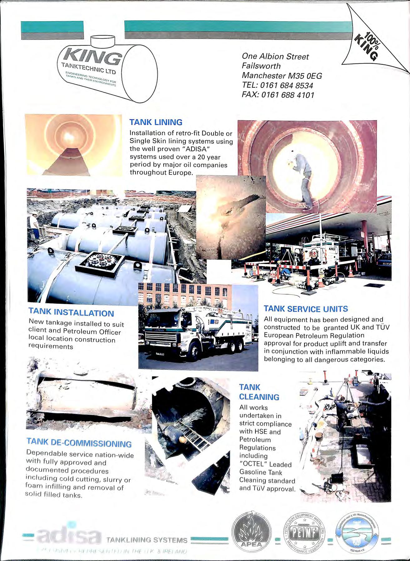
New tank age installed to s uit client and Petroleum Officer local location c onstruction re quirements
r
I ! SYSTE M S IJi!iW!iil!illl!!!!lliiillMli!IJUJlll ,, I I ,/ 11{ I /!{ i'f-1/ ',f /\/ '/ {.IN Tf-!t I I r. 8 !HE! AiV{)
TANK Dependab le se
v ice nat ion-w ide with fu ll y approved a n d documented procedures inc l ud i ng cold cutting, s l urry or fo am inf i lling and remova l of so li d fille d tanks
One Albion Street Failsworth Manchester M35 OEG TEL: 0161 684 8534 FAX: 0161 688 4101
• erv1ces National Inspection Council for Electrica Installation Contr2ctmg G:':JDI]§ E•C APPROVED CONTRACTOR UNIT 10 MERTHYR TYDFIL INDUSTRIAL PARK PENTREBACH MEMBER OF MERTHYR TYDFIL W BRm'" "'"" couNm MID GLAMORGAN CF48 4DR )j C-.YESTOR L'\ PEOPLE Telephone: (01443) 692008 Fax:(01443)692159 E Mail: gcs ltd@btinternet.com Fuel tank, pipework & pump installations. Stage 1 B vapour recovery installations. Fuel monitoring & metering equipment. EfL'JZ 'ft' 'JJfl' 'JJ"t' tJJ"(' 'JJEfu' 'JJEfG' 'J 'tCi 'fo1&i 'Ja Fuelling planes, trains or automobiles? (or anything else for that matter) f I r lu be-oil. Full range e approved and in-house models, for petro l, derv 0 ets the Range of d1spens1ng speeds from 45LPM to 14oLPM. All equ ipment me latest standards, is manufactured out of stainl ess steel and bui lt to last. R ad North For more 1nformat1on p lease contact PUMPTRONICS at Fo lgate o ' Wal s ham, Norfolk, NR28 OAJ . Tel: 01692 500640, Fax : 01692 406710 .

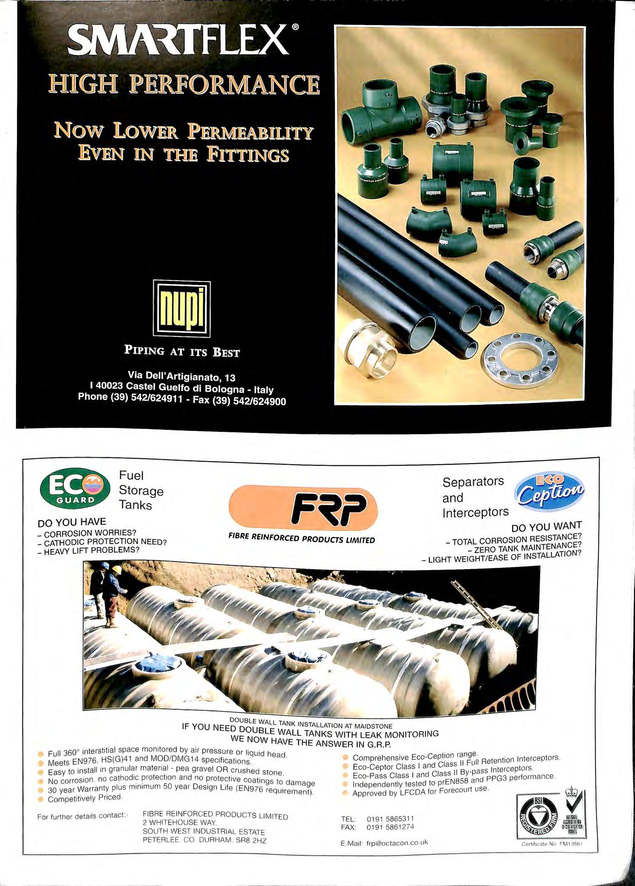
Fuel Storage Tanks Separators and Interceptors FIBRE REINFORCED PRODUCTS LIMITED DO YOU WANT RESISTANCE? TOTAL ZERO TAN LATION? LIGHT WEIGHT / EASE OF INSTAL DOUBLE WALL TANK INSTALLATION AT MA IDSTON E IF YOU NEED DOUBLE WALL TANKS WITH LEAK MONITORING WE NOW HAVE THE ANSWER IN G . R.P. 0 ters titial space mon itore d by air pressure o r liq uid head. • Full HS (G)4 1 and MOD/DMG 14 specifi ca tions • Meets 1 11 ' in granu lar material pea grave l OR crush ed sto ne • Easy to ins a no cathodic protect ion an d no protect ive coa tin gs to damage • No corrowsion nty plus minimum 50 year Des ign Life (EN 976 requ ireme nt) 3o year arra • Co mpetitively Pri ced Fo r further details co ntact :- FIBRE RE INFORC ED PRODUCTS LIMITED 2 WHITEHO USE WAY. SOUTH WEST INDUSTR IAL ESTATE PETER LEE CO DURHAM SR8 2HZ t n range tors • Com prehensive Eco Cep io II Fu ll Retention lnte rcep e Eco Ceptor Class I and Class _ ass Interceptors Eco Pass Class I and Class II By p d PPG3 performance d t prE N858 an l odopeodco Uy ' "" 1° Focecm1rt "" Approved by LFCDA or @G. I TEL : 0191 5865311 FAX: 0191 586 1274 · • 1 E Mail : frp @octacon.co.uk Ccrtif1 c.:l tO N o l=M1 35Gl
Durapipe - S&LP EMCD WHEATON • environ A\n1e•11on <>PWFUELi NG COMPONENTS EUROPE B Y. -=A DOVER RESOURCES COMPANY -=""' AND MANY MORE The Worlds Major Forecourt Products from the UK's Major Distributor ., , D Bmy & Co (Pipe fittin g Supplies) Ltd , 1W Un it 130, Middlemore Indu stria l Estate, Kentish Road, B'ham 821 OAY. Tel : 0121 558 4411 Fax : 0121 555 5546 AO \f f ''i!/ ffi/Aflf>.'I. 0 1 . •
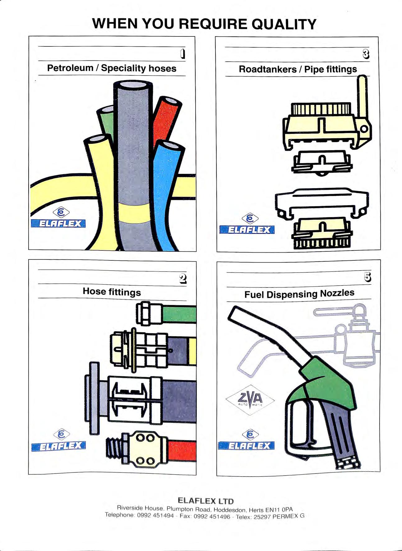
WHEN YOU REQUIRE QUALITY Petroleum I Speciality hoses Roadtankers I Pipe fittings Hose fittings Fuel Dispensing Nozzles _,/ / ElAFLEX LTD Rivers ide House Plumpton Road Hoddesdon He1is EN11 OPA Te lephone 099 2 451494 Fa x 099 2 451496 Te le x 2529 7 PE RM EX G
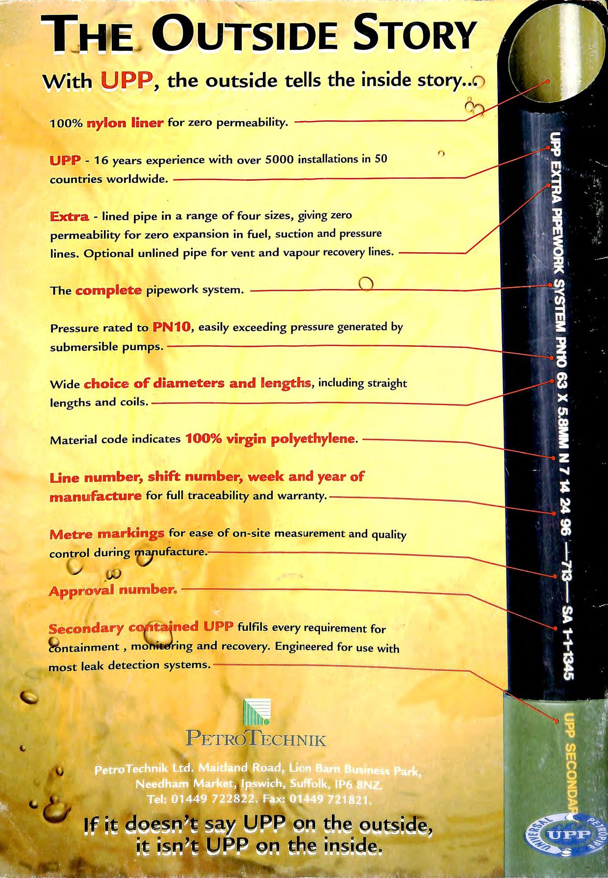
UPP 16 years experience with over 5000 installations in SO countries worldwide. ------------:-------======----Extra lined pipe in a range of four sizes, giving zero permeability for zero expansion in fuel, suction and pressure lines. Optional unlined pipe for vent and vapour recovery lines. Pressure rated to PN10 , easily exceeding pressure generated by submersible pumps. Wide choice of diameters and lengths, including straight lengths and coils. --=-----------------::--------Une number, shift number, week and year of manufacture for full traceability and warranty. Metre markings for ease of on-site measurement and quality control during 'Ci" ufacture Approval number.--------- ------ --Secondary c - ·ned UPP fulfils every requirement for 'B ntainment , mo ing and recovery Engineered for use with most leak detection systems. --------------....
