The •
THIS ISSUE FORECOURT CONTROL TANK TESTING UNDERGROUND STORAGE TANKS USA v UK j, VOLUME28 No. 4
Journal of the Association for Petroleum and Explosives Administration
Ameron's Dualoy®3000/L fib erglass piping is li s ted with Underwriters' Laboratories for use in und er gro und fu e l-handlin g syste m s It h as a lso been tested and acce pted by th e London Fire and Civil Defe n ce Authorit y.
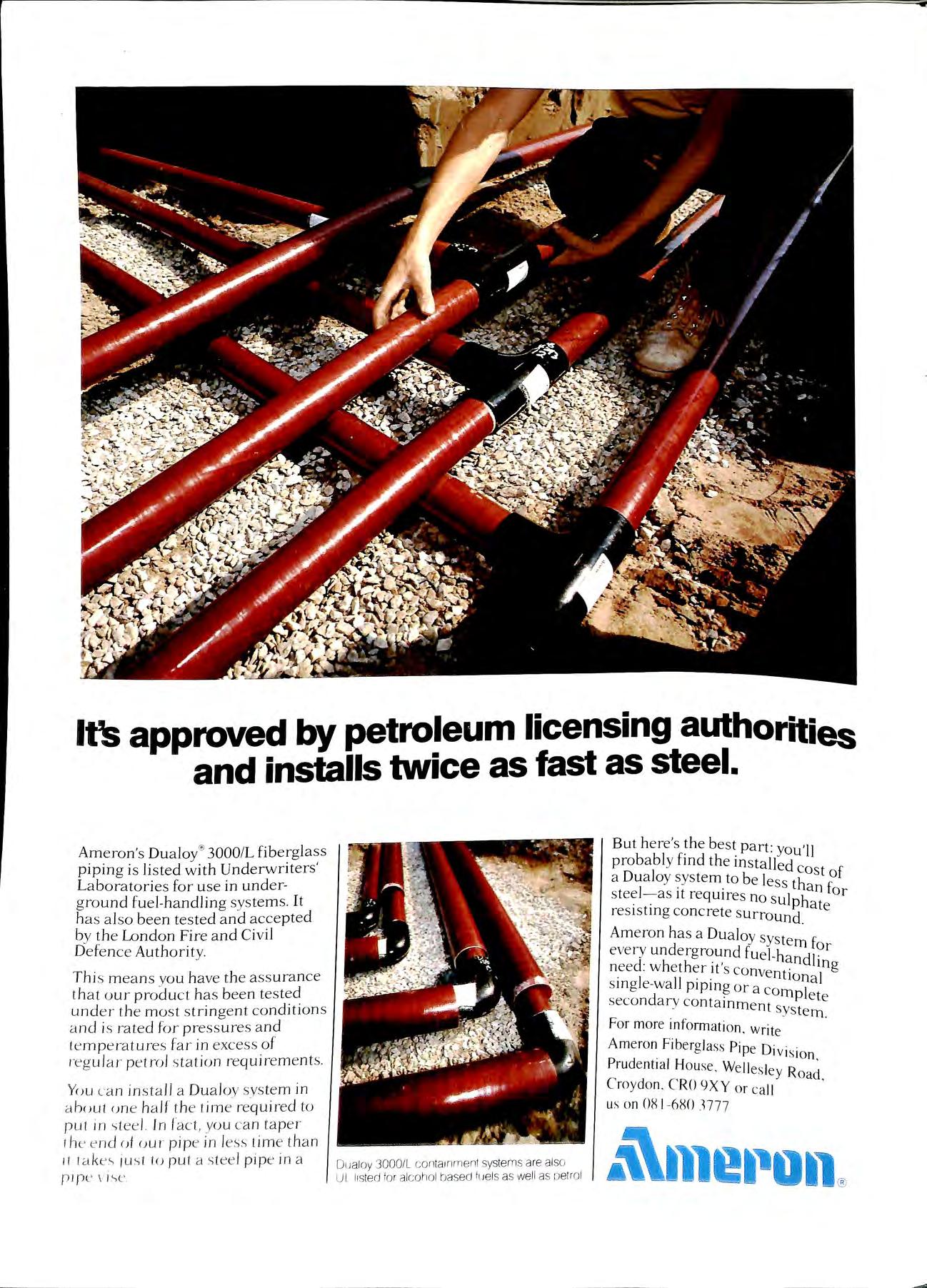
Thi s m ea n s you have th e ass ura n ce th a t our product ha s b ee n tes te d und er th e mo s t s trin ge nt co ndition s a nd is rat e d for press ures a nd te mp era tures far in excess o f reg ul ar petro l s tation re quire m e nt s Yuu ca n in sta ll a Du a loy sys te m in a h()uf un e h a lf t h e t im e req uire d to pul in -;tee l. Jn fact, you c an tap e r the e nd ()1 uu r pip e in less t im e t h an 11 tak e'> ju s t tu put a s tee l pipe in a p i pl' \ l.'>e
But h e re's b es t part: yo u'll proba bl y fmd the installed a Du a loy sys tem to be les host of s tee l as it requires no s sl tha n for resisting concrete ate Ameron has a Dualoy syste · every und e rground fuel-h 111 for n ee d : whether it's conve ta ndlin g s in g le-wa ll piping or a 10 n a ] seco nd ary co ntainme t mpl e te . n sys tem .
For more infonnation w 1 · n e Am e ron Fibergla ss Pipe o· .. . 1v1 s1o n Prudentia l House. Welle s le R · · Y oact Cro ydo n CRO 9XY or ca ll ' us on 08 1 680 3777
It's approved by petroleum licensing authorities and installs twice as fast as steel.
Dualoy 3000/L co ntainm ent systems are also UL listed for alcohol based fuels as well as petrol
C p INSTALLATIONS LTD. (Established 1968) Specialists in Petroleum Pipework Installations New and existing Tanks and Lines tested Modifications to existing Installations And all work associated with Forecourt Pipework 39 BROOK ROAD, RAYLEIGH WEIR INDUSTRIAL ESTATE RAYLEIGH, ESSEX SS6 7XN Tel: 0268 781184 / 781859 (24 hrs ans) Fax: 0268 776697 PHONE: 071-739 9538 FAX: 071-729 6108 TUBEFLOW LTD SPECIALISTS IN PETROL PUMP, TANK AND PIPEWORK INSTALLATIONS AND ASSOCIATED WORKS APPROVED CONTRACTORS TO THE PETROLEUM INDUSTRY AND LOCAL GOVERNMENT AUTHORITIES 29 TEMPLE STREET, LONDON E2 6QQ MEMBER A.P.E.A.
-W. LAMB LTD. THE PREMIER PUMP AND TANK COMPANY Forecourt and Commercial Above and Below Ground Supply Test Exchange Service lnstal Product Transfer De-Watering Removal Purchase Tank Demolition - Removal - Safety Filling Large Stocks of New and Secondhand Petrol and Diesel Pumps, Tanks and Accessories DAVB ROOK STREET, SHERWOOD, NOTTINGHAM 0602 621511 + 608084 TRINITY WORKS, BOURNE END LANE, HEMEL HEMPSTEAD 0442 872296 WJ FINCH LTD (INSTALLATIONS and CONTRACTORS) Regd. Office: HEATON HOUSE 121 - 137 CAMDEN STREET BIRMINGHAM Bl 3BZ Tel: 021 236 034? Fax: 021 236 s1 45 OFFERING A TOTAL SERVICE COVERING ALL ASPECTS OF FORECOURT REQUIREMENTS, RANGING FROM CONSTRUCTION & INSTALLATION OF COMPLETE NEW BUILD OR REDEVELOPMENT ' WITH FULL DESIGN & BUILD OPTION, TO GENERAL PIPEWORK & PUMP=TANK INSTALLATION & TESTING, IN ADDITION TO OUR GENERAL SITE MAINTENANCE WORKS. ESTABLISHED 1964
TAMES LuKE ASSOCIATES Safety & Training Consultants to the Petroleum Retail Industry ) li!!'illlllllllBlli'll, SALUKI HOUSE 4 BURNT COMMON CLOSE RIPLEY, SURREY GU23 6HH Tel: 0483 222946 Fax: 0483 211328 1 obn Uigf ull & <!o. Jltb. FIRST HANGINGS BLABYROAD ENDERBY LEICESTER LE9 SAQ Telephone (0533) 862287 Fora Comprehensive service for liquid fuel & LPG installations Consu/Jancy, design, installation, maintenance & decommissioning Gasafree certificates Site surveys LPG vessel 5 & 1Oyear inspections MEMBER AP EA, LPGITA DESIGN FUELLED B EXPERIENC Personal attention in design & development for the petroleum retail industry • Principal with over 25 years experience • Project Management specialists • Progress ive & inn ovative outlook • Consultants for statutory & planning requirements • Comprehensive or tailored service to suit PLANACOURT Planacourt Limited PO. Box 27 Bill ericay Essex CM ll 2ES 0277 630868
C · S ·STANSFIELD MECHANICAL SPECIALISTS IN FORECOURT PETROLEUM INSTALLATIONS SERVICES Unit 10 Boundary Road Industrial Estate Sturmer, Haverhill Suffolk, CB9 7YH Tel: 0440 712505 Fax: 0440 712506 BELHAN CONSTRUCTION CO LTD Building Contractors (Est 1970) Comprehensive Development and Maintenance Services By Petrol Station Specialists 58 St. Andrews Road Shoeburyness Essex SS3 9JJ Tel: 0702 295197
MANGAN BROS. LTD. Building Contractors 402 Seven Sisters Road, London N4 2LU (REGISTERED OFFICE) Telephone: 01 800 4651 Specialists in Petrol Filling Stations D. S. Leggett (Electrical) Limited ELECTRICAL CONTRACTORS N/CEIC APPROVED 181 VICTORIA ROAD, NEW BARNET, HEATS. 01-441 3958 SPECIALISTS IN PETROL STATIONS
Introducing from the new 61-SO Overfill Prevention Valve
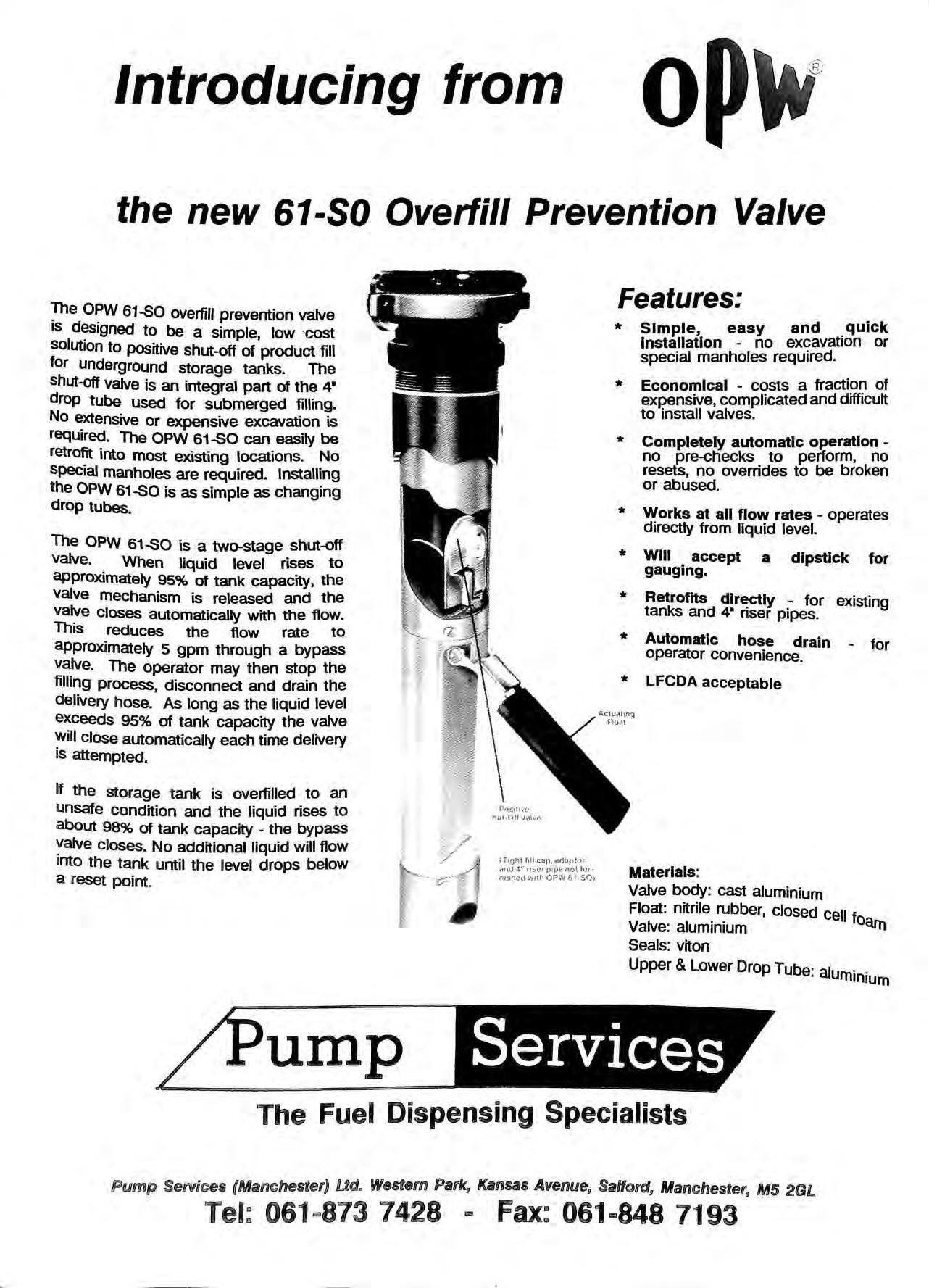
!f1e 61-SO overfill prevention valve is to be a simple, low cost solution to positive shut-off of product fill for underground storage tanks. The shut-off valve is an integral part of the 4" drop tube used for submerged filling. No extensive or expensive excavation is required. The OPW 61-SO can easily be retrofit into most existing locations. No Special manholes are required. Installing the OPW 61-SO is as simple as changing drop tubes.
The OPW 61-SO is a two-stage shut-off valve. When liquid level rises to approximately 95% of tank capacity, the valve mechanism is released and the Valve closes automatically with the flow. This reduces the flow rate to approximately 5 gpm through a bypass valve The operator may then stop the filling process, disconnect and drain the delivery hose. As long as the liquid level exceeds 95% of tank capacity the valve close automatically each time delivery ts attempted
If the storage tank is overfilled to an unsate condition and the liquid rises to about 98% of tank capacity the bypass closes No additional liquid will flow into the tank until the level drops below a reset point.
* Simple, easy and quick Installation no excavation or special manholes required.
* Economical costs a fraction of expensive, complicated and difficult to install valves.
* Completely automatic operation no pre-checks to perform, no resets, no overrides to be broken or abused.
* Works at all flow rates operates directly from liquid level.
* Will accept a dipstick for gauging.
* Retrofits directly for existing tanks and 4" riser pipes.
* Automatic hose drain for operator convenience.
LFCDA acceptable
ump (Tight fill cap. MJ<.Jp tvr <'Ind 4" nsei pipe nol fu1 n.:sh€'C! v;!th OPVJ o 1-so i
Features:
Materials: Valve body: cast aluminium Float: nitrile rubber, closed ceu f Valve: aluminium oarn Seals: viton Upper & Lower Drop Tube· alum· · 1n1um Services The Fuel Dispensing Specialists Pump Services (Manchester) Ud. Western Kansas Avenue, Salford, Manchester, M5 2GL Tel: 061..,873 7428 tm Fax: 061..,848 7193
*
On October 2nd ERIC FORTH opened the APEA seminar at Dunstable which proved to be the laro-est conference hosted by the Association. Delegates from USA Europe, Africa as well as the UK gave the seminar international flavour, and a full house of 400 delegates meant that several late applicants had to be turned away. The Minister launched HS(G)41 at that meeting and the Association welcomes its publication.
It supports fror:i the Oil Industry that early reconvemng of the committee will be necessary to
Give guidance on interpretation
Review new installation techniques, new materials and tank testing technology in what has become rapidly changing times.
VOLUME, 28 Number4 NOVEMBER 1990 £5.00 (Free to Members) Contents TALKING POINT NOTES & NEWS LETTERS TO EDITOR FORECOURT CONTROL The Bulletin
the Association for
Explosives
company Limited by Guarantee
Reg.
49 50 53 55
Published by
Petroleum and
Administration A
registered in England No. 2261660
Office: Stoughton House, Harborough Road, Oadby, Leicester LE2 4LP ISSN 0263 4597
Opinions expressed in this Journal are not necessarily the views of the Association
Talking Point
BACK TO THE
FUTURE
BRANCH MEETINGS NEW MEMBERS UNDERGROUND TANK TESTING HUMBERSIDE BRANCH J. Horsburgh EASTERN BRANCH R. G. Green Honorary Secretary: Mr. B. D. Taylor, 58 59 63 SOUTHERN BRANCH M.Cox Normond Instruments Ltd.,
1)
2)
MEMBERSHIP SECRETARY B. J. Thompson MIDLAND BRANCH Mr. L. Lloyd CMS Ltd. ADVERTISING SECRETARY J. Luke 49 Honorary Editor: Mr. J. A. J. Thompson,
(UST)
57
EMPLOYMENT'S "GREEN MINISTER" OPENS APEA SEMINAR
Eric Forth, the Employment Department's new "Green" Minister, delivered the opening address to the APEA petroleum seminar as his key engagement during a visit to Bedfordshire on Tuesday 2 October.
Mr Forth, who is the Minister responsible for health and safety issues, opened the International Petroleum seminar and exhibition in Queensway Hall, Dunstable.
The Minister took up his new environmental role following the launch by Environment Secretary Chris Patten of the Government's White Paper on the Environment. The Employment Department is responsible for training, tourism and health and safety, all of which have a significant impact on Britain's environment.
At the seminar, organised by the Association for Petroleum and Explosives Administration, the Minister's 400-strong audience included delegates from other European countries and the United States.
He toured the exhibition of 38 companies displaying products manufactured for use in petrol stations.
REVISION ON CODES FOR FLAMMABLE LIQUIDS
Precautions for firms to take against the potential hazards from storing flammable liquids on their pre1:nises are set out in two guidance documents recently pubhshed by the Health and Safety Executive (HSE).
They deal respectively with the design, construction, operation and maintenance of (i) installations used for storing flammable liquids in fixed tanks a total inventory of up to 10,000 cubic metres). and (11) storage areas for portable containers.
The precautions are designed to minimise the risk of fire and explosion involving stored liquids, or the escape of liquid or vapour. They do not deal with from external source, such as a major incident affectmg a wide area, or with toxic, corrosive or oxidising hazards posed by particular flammable liquids.
Work on new designs or on modifications to existing storage areas should follow the advice set out in the guidance; people who manage existing areas should consult the guidance to see whether there are any reasonable practicable improvements they should make to their storage arrangements.
However. variations from the recommendations may be appropriate to local conditions so long as they provide equivalent or higher overall safety.
The storage of flammable liquids in fixed tanks (up to I o.ooom.i total capacity J. HS(G )50, ISBN 0 l l 885532 8, is priced at £3.75 and: The storage of flammable liquids in containers. HS<G )5 I. ISBN 0 11 885533 6. costs £3.50.
Both are available from HMSO.
PIPE JOINT PROBLEMS WITH PTFE TAPE
Two recently completed redevelopments of petrol filling stations have been closed and the suction lines have been dug up again after the lines had been found to be leaking.
It would appear that a contractor from the Rotherham area used PTFE tape on the underground line joints. The lines which apparently held up to pressure test before concreting, began leaking within a short time of being used. Some concern is being expressed within the area by petroleum licensing authorities as to how many other sites may be similarly affected.
GRP TANKS DAMAGED
A recent GRP tank installation in the Manchester area recently caused some concern when the tanks were damaged before installation. The first problem occurred when the tank rib was damaged by a contractors JCB. and then ":'ere damaged by vandalism which the police are mvestigatmg. The installation was eventually completed satisfactorily and all the tanks were replaced with new ones.
In North London two separate incidents within 10 days where the GRP tank was mishandled from the lorry and fell to ground ?amaging the neck. Another was damaged in transit to the site. In both cases the tanks were returned and new tanks made to replace these.
It would that better training in the handling of G.R.P. products seem necessary for all contract . t II" G.R.P. tanks. ors ms a mg
FEES FOR PETROLEUM LICENCES: HEALTH AND SAFETY (FEES) REGULATIONS 1990
FEES PAYABLE TO KEEP PETROLEUM SPIRIT
Item
For a licence to keep a quantitynot exceeding 2,500 litres exceeding 2,500 litres, not exceeding 50,000 litres exceeding 50,000 litres for transfer of a licence
Current Fees
Proposed Fees
£22 per annum £24 per annum
£33 per annum £36 per annum
£65 per annum £71 per annum £6 each £7 each
FIREWORK FACTORY EXPLOSION: ONE FATALITY
A man died in an explosion at the Le Maitre f. f · p b 1reworks actory m eter orough, Cambridgeshire on 6th s t b · Th · h. · · ep em er e m 1s 1s believed to have been killed when fireworks on which he was working exploded.
The Company in firework displays for pop concerts and events. In 1988 a worker died when sparks 1gmted fireworks. which blew up and demolished a wooden workshop.
notes
and news
'iO
BP BANS BBQ FUEL
Following a major fire on one of its stations, BP has stopped stocking liquid barbecue fuel on company-owned premises.
The fire was caused by a leaking container of barbecue fuel on a stand outside the forecourt shop. The canopy was burnt out, the shop front partially melted and the entire shop stock destroyed or smoke-blackened.
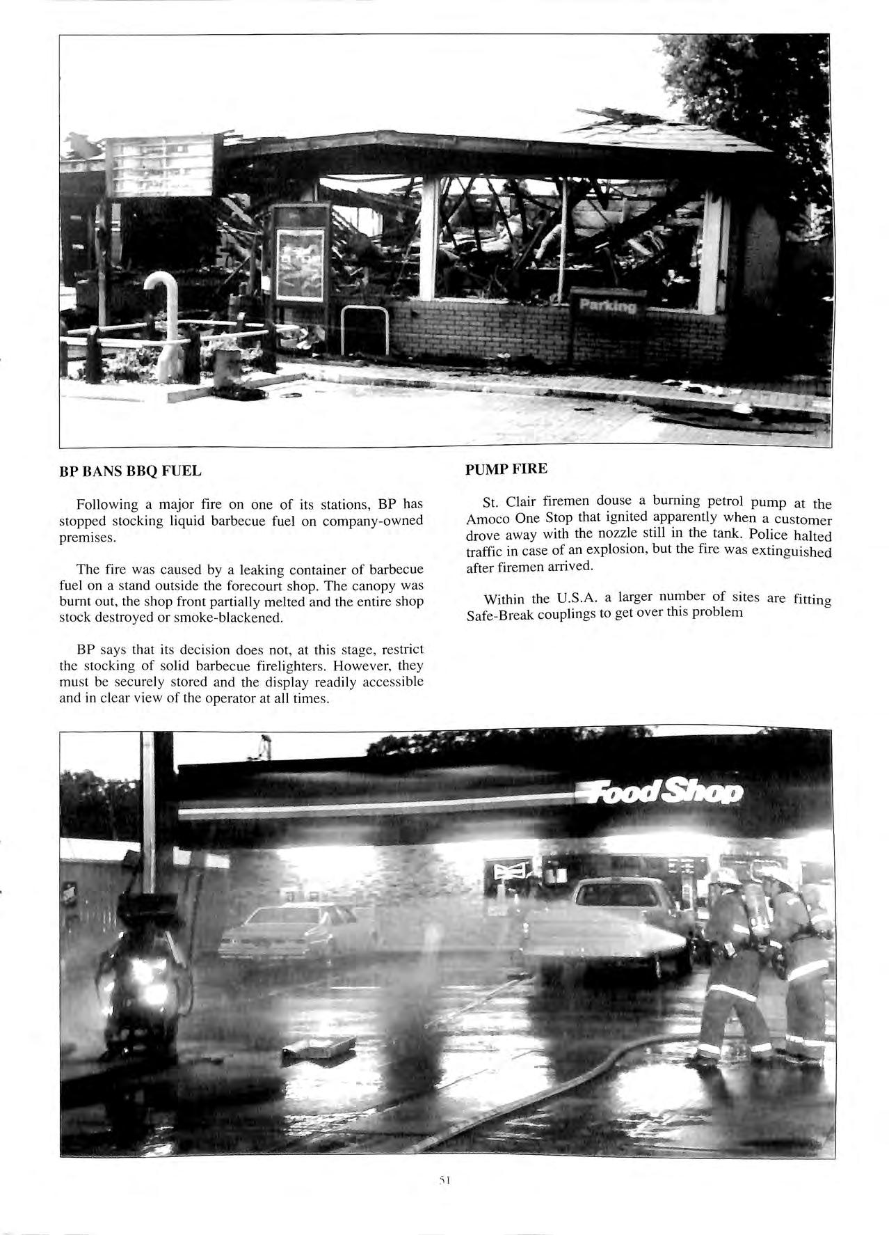
BP says that its decision does not, at this stage, restrict the stocking of solid barbecue firelighters. However, they must be securely stored and the display readily accessible and in clear view of the operator at all times.
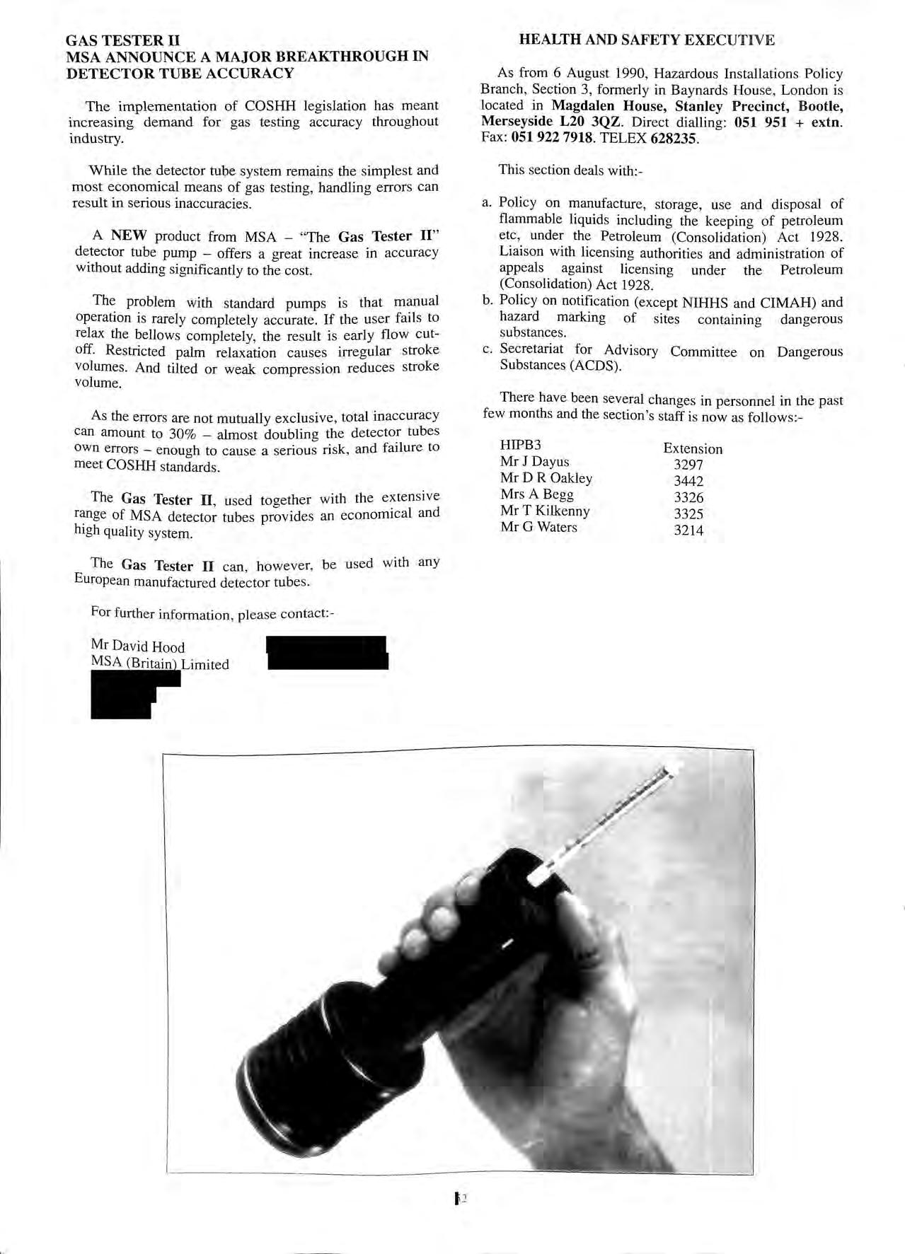
PUMP FIRE
St. Clair firemen douse a burning petrol pump at the Amoco One Stop that ignited apparently when a customer drove away with the nozzle still in the tank. Police halted traffic in case of an explosion, but the fire was extinguished after firemen arrived.
Within the U.S A. a larger number of sites are fitting Safe-Break couplings to get over this problem
5 1
TESTER II
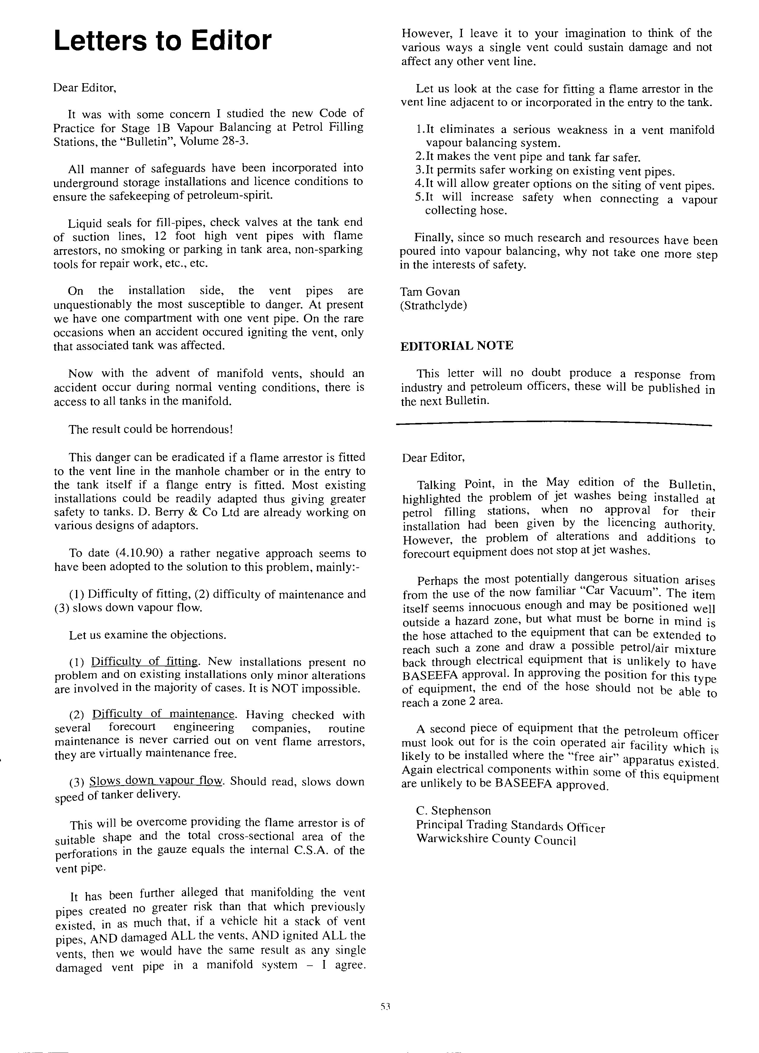
MSA ANNOUNCE A MAJOR BREAKTHROUGH IN DETECTOR TUBE ACCURACY
The implementation of COSHH legislation has meant increasing demand for gas testing accuracy throughout industry.
While the detector tube system remains the simplest and most economical means of gas testing, handling errors can result in serious inaccuracies.
A NEW product from MSA "The Gas Tester II" tube pump offers a great increase in accuracy without adding significantly to the cost.
The problem with standard pumps is that manual operation is rarely completely accurate. If the user fails to relax the bellows completely, the result is early flow cutoff. Restricted palm relaxation causes irregular stroke volumes. And tilted or weak compression reduces stroke volume.
As the errors are not mutually exclusive , total inaccuracy can amount to 30% _ almost doubling the detector tubes own errors enough to cause a serious risk, and failure to meet COSHH standards.
The Gas Tester II, used together with the extensive of MSA detector tubes provides an economical and high quality system.
The Gas Tester II can , however, be used with any European manufactured detector tubes.
For further information, please contact:-
Mr David Hood MSA (Britain) Limited
HEALTH AND SAFETY
As from 6 August 1990, Hazardous Installations Policy Branch, Section 3, formerly in Baynards House, London is located in Magdalen House, Stanley Precinct, Bootle, Merseyside L20 3QZ. Direct dialling: 051 951 + extn. Fax: 051 922 7918. TELEX 628235.
This section deals with:-
a. Policy on manufacture, storage, use and disposal of flammable liquids including the keeping of petroleum etc, under the Petroleum (Consolidation) Act 1928. Liaison with licensing authorities and administration of appeals against licensing under the Petroleum (Consolidation) Act 1928.
b. Policy on notification (except NIHHS and CIMAH) and hazard marking of sites containing dangerous substances.
c. Secretariat for Advisory Committee on Dangerous Substances (ACDS).
There have been several changes in personnel in the past few months and the section's staff is now as follows:-
HIPB3
Mr J Dayus
MrDR Oakley
Mrs A Begg
Mr T Kilkenny
Mr G Waters
Extension 3297 3442 3326 3325 3214
GAS
2
EXECUTIVE
Letters to Editor
Dear Editor,
It was with some concern I studied the new Code of Practice for Stage 1B Vapour Balancing at Petrol Filling Stations, the "Bulletin", Volume 28-3.
All manner of safeguards have been incorporated into underground storage installations and licence conditions to ensure the safekeeping of petroleum-spirit.
Liquid seals for fill-pipes, check valves at the tank end of suction lines, 12 foot high vent pipes with flame arrestors, no smoking or parking in tank area, non-sparking tools for repair work, etc., etc.
On the installation side, the vent pipes are unquestionably the most susceptible to danger. At present we have one compartment with one vent pipe. On the rare occasions when an accident occured igniting the vent, only that associated tank was affected.
Now with the advent of manifold vents, should an accident occur during normal venting conditions, there is access to all tanks in the manifold.
The result could be horrendous!
This danger can be eradicated if a flame arrestor is fitted to the vent line in the manhole chamber or in the entry to the tank itself if a flange entry is fitted. Most existing installations could be readily adapted thus giving greater safety to tanks. D. Berry & Co Ltd are already working on various designs of adaptors.
To date (4.10.90) a rather negative approach seems to have been adopted to the solution to this problem, mainly:-
( 1) Difficulty of fitting, (2) difficulty of maintenance and (3) slows down vapour flow.
Let us examine the objections.
( 1) Difficulty of fitting. New installations present no problem and on existing installations only minor alterations are involved in the majority of cases. It is NOT impossible.
(2) Difficulty of maintenance. Having checked with several forecourt engineering companies, routine maintenance is never carried out on vent flame arrestors, they are virtually maintenance free.
(3) Slows down vapour flow. Should read, slows down speed of tanker delivery.
This will be overcome providing the flame arrestor is of uitable shape and the total cross-sectional area of the in the gauze equals the internal C.S.A. of the vent pipe.
It has been further alleged that manifolding the vent pipes created no greater than. that _which previously existed in as much that, 1f a vehicle hit a stack of vent pipes, AND damaged ALL the vents, AND ignited ALL the vents then we would have the same result as any single vent pipe in a manifold system -I agree.
However, I leave it to your imagination to think of the various ways a single vent could sustain damage and not affect any other vent line.
Let us look at the case for fitting a flame arrestor in the vent line adjacent to or incorporated in the entry to the tank.
I.It eliminates a serious weakness in a vent manifold vapour balancing system.
2.lt makes the vent pipe and tank far safer.
3.lt permits safer working on existing vent pipes.
4.It will allow greater options on the siting of vent pipes.
5.lt will increase safety when connecting a vapour collecting hose.
Finally, since so much research and resources have been poured into vapour balancing, why not take one more step in the interests of safety.
Tam Govan (Strathclyde)
EDITORIAL NOTE
This letter will no doubt produce a response from industry and petroleum officers, these will be published in the next Bulletin.
Dear Editor,
Talking Point, in the "M:ay edition the Bulletin, highlighted the problem of Jet washes bemg installed at petrol filling stations, when no for their installation had been given by t?e licencmg authority. However, the problem of and additions to forecourt equipment does not stop at Jet washes.
Perhaps the most arises from the use of the now familiar Car Vacuum The item itself seems innocuous enough and may be positioned well outside a hazard zone, but what must be borne in mind is the hose attached to the equipment that can be extended to reach such a zone and draw a possible petrol/air mixture back through electrical that is unlikely to have BASEEFA approval. In approvmg the position for this type of equipment, the end of the hose should not be able to reach a zone 2 area.
A second piece of equipment that the petroleum ff" " · h · o 1cer must look out 1or 1s t e com operated air facility h' h . likely to be installed where the "free air" apparatu ,w 1.c is s existed. Agam electncal components w1thm some of thi's · eqmpment are unlikely to be BASEEFA approved.
C. Stephenson Principal Trading Standards Officer
Warwickshire County Council
53
DTP'S v BC: no, not dsd's!
by J D Johnson G!FireE (Petroleum and Explosives Officer for West Yorkshire Fire Service
I am minded, at this time, to put pen to paper as the old adage goes, although when I start, it is in pencil, in order to compile notes and tends to go on a bit, I think, however, the old topic of 'forecourt control' does need airing again, together with, in my opinion, a new area of concern.
Problems have arisen in my area and I know they exist in other areas and which I believe have now to be taken on board by way of applying Additional Conditions to Licences because the matter is getting worse and not being addressed by Licensees themselves. Licensees will, of course, plead the usual mitigation, as one did last week, and state that "other authorities are not pursuing these matters, we have built similar or we have the same arrangements in other parts of the country and they have been approved". When this is stated I wonder how many authorities actually oversee installations in operation rather than oversee construction work and interest ceases following licence issue? How many Officers I wonder were about at the advent of self service and know the reasons why additional conditions for such use were made?
One problem area has obviously arisen before as a very good and comprehensive article appeared in the July 86 Bulletin by Barry Lowe Forecourt Sales The Enforcement View. Has any Authority had to act, however, in these matters since highlighted years ago. or is everyone complying with what is reqmred? I do not mtend to rake over the coals but the specifics with regard to 'forecourt control' requirements note, requirements meaning mandatory not optional do need to be reemphasised, particularly the practical aspect of 'control'. It appears from the attitude of many Licensees, and not just the small independent trader, one could go on emphasising and re-emphasising from now until doomsday without effect. Is this also the outcome elsewhere?
I add two areas of concern. One is related to that mentioned above which highlights the need for extra vigilance in the matter of forecourt control and which I term the 'DTP' principle 'Drive to Pay' and the other which I term the 'BC' syndrome 'Bazaar/Convenience Store' arrangements. My first concern is that of the 'DTP' principle, where a customer refuels the vehicle and instead of walking to the kiosk to pay, the customer gets back into the vehicle and drives to a kiosk to pay a cashier. Invariably this type of installation is sited adjacent to a large supermarket which caters for the shopping needs of the customer hence there is no need for the usual kiosk with shop. Additionally there is usually two kiosks side by side to cater for a cashier for each island with provision for up to four dispensers (8 sides) per cashier.
It is stated that the 'DTP' principle provides an additional 33% volume of sales when compared with a conventional type installation with similar number of dispensers. One would easily come to the conclusion therefore that if the required 'Forecourt Control' is not being provided for a conventional system. and I agree with the remarks of Barry Lowe and I have evidenced the failure to control. then 'control' cannot he exercised at a system which is designed and provides for a greater throughput of vehicles. by one person who is a cashier.
At peak trading periods, which tend to equate with the adjacent peak supermarket shopping times, Thursday, Friday evenings and Saturday mornings, Officers have evidenced that it is impossible for the two cashiers in their respective kiosks to give the required practical 'control' of the forecourt. Practically, the cashier is dealing with a paying customer, invariably not a simple task as with just cash payment but also cash card requiring receipt, from a customer outside in one vehicle parked at the kiosk. There are also four further vehicles, two side by side, queuing between dispenser island and the one parked and a minimum of four vehicles, depending on number of dispensers, at dispenser positions either waiting for their dispenser to be commissioned or have had the dispenser commissioned and are dispensing. Additionally vehicles are waiting for a vacant dispenser position, in total some eleven vehicles per island, with four dispensing positions. How on earth one cashier deals with up to eight dispensing positions I don't know. Well, I do. It is because no actual practical control of what is happening on the forecourt is carried out. Dispenser commissioning is done by sight and the sound of the bleeping on the control equipment with a cursory glance only, up to the forecourt.
In my view control means practical control not theoretical. The requirement being to pre\'ent a dangerous situation occurring not necessarily only being able to deal with a dangerous situation when it has occurred. I only indicate here, as a reminder, of some of the points which must be taken into account by the person who is controller before a dispenser is commissioned and during refuelling: Is the loudspeaker system in working order and the microphone, where it is of the moveable type, positioned for immediate use? If it is defective the installation cannot operate as self-service. Can the vehicle be seen at the dispenser? If it cannot be seen for whatever reason, a line of parked vehicles, a high sided vehicle or the dispenser itself (these wide multi-product dispensers) is obstructing vision, that specific dispenser cannot be commissioned. Is the vehicle's engine running? is anyone smoking in the danger area, is the person about to dispense fuel over 16 years of age, if a container is to be filled is it of an approved type correctly labelled. If the answer to the questions is in the bearing in mind that without asking the customer via the loudspeaker system, note the required use of further kiosk equipment, to produce the container to the controller to verify correct type, the respective dispenser cannot be If motor spirit is permitted to be dispensed mto an unapproved container, the offence has already been committed! Also of course, during refueling, anticipating the opening of the boot lid to take out a container, having left the dispenser delivering fuel by way of the vehicle filler cap pushed into the nozzle trigger guard to hold the latch open!, the stretching of the hose like a bow string across the back of the vehicle and trying to force the nozzle 'round the comer'. All of which are malpractices required to be corrected by the person in the kiosk through the tannoy system? and only a cashier does all this, during peak trading times while also dealing with a constant flow of some 30% more vehicles! How is control effective in this instance when it cannot be done at a convenient type installation.
'i4
Add one most important and usually forgotten fact. When any number of dispensers are dispensing fuel into vehicles, each side of each respective dispenser can now be operated at the same time, speeding up the whole forecourt.
Additionally, with the modern electronic equipment in the kiosk the cashier can 'stack' sales at dispensers, permitting even speedier operation. In this case is not at least double the time spent on control required? It was not long ago that a dispenser could only be operated one side at a time, a customer on one side having to wait until the other completed delivery and the equipment zeroed before recommencing delivery -a much slower operation and much easier to control.
What of training for the supposed controller? What really bugs me is the lack of training given in respect of matters of control to persons who are invariably employees, by their respective employers in this most specific and important area. Bearing in mind the point previously mentioned, the requirement to actually control, contained in Conditions of Licence, a large number of installations specifically designed for self service use, should in practice, be operating as attended service installations because of failure to comply with what is required by way of practical and effective control.
I have spoken with many National Company's Training Officers recently and asked to discuss their documentation relating specifically to the training of the 'controller' and if there is a section within their schedules that specifically relates to the important position the controller holds? Also if the importance of the position is doubly underlined in that the acceptance of the self service facility is only granted on condition of the controller practically doing what he/she is required to do and then training them in what to do and ensuring that they control effectively. In many cases the above matters are not provided for in their training. Many matters are covered, every company policy, how to operate everything to do with the shop, equipment in the shop or kiosk, all about emergency switches for electrical equipment, how to operate and use the fire equipment in actual fact every conceivable circumstance, except the most important one that of practical control of the forecourt. This fact of the non-provision of specific training is based on the evidence by myself asking employees purporting to be controllers of the training they have been given in the specifics, not just general, and invariably the answer is none.
In all this, am I barking up the wrong tree and not being able to differentiate the wood from the timber!
My second area of concern, as previously mentioned, is the 'BC' syndrome. This syndrome reminds me of Xmas but is constant all year round. I have recently had to remonstrate rather with a Licensee because at his installation there was twice as merchandise for resale, 99 % of which comes w1thm the classification of mbustible. out on the forecourt as there was in the co . . h forecourt shop. This was not a ere he might have had an excuse to say that 1t was his tenant in the . d'oining premises and he would have words! This was his a J b 'Id' . own shop/kiosk, no other were mvolved. I could not even remember a total hst ol s_tock. there was so much. to such an extent that customers trom the forecourt had to walk through an alleyway of goods before even reaching the shop entry door. Although rn!t positioned within the normal safety distance nt the dispensers. I was
thinking of how the persons inside the building would get out through the door if all the goods outside caught fire as it was all under an overall canopy to forecourt and building.
A previous inspection of the premises found that the forecourt emergency switch for the dispensers was obstructed by stock on the forecourt and a photograph taken for evidence purposes at another time showed forecourt stock obstructing the view of the controller of the forecourt from the kiosk!
The above instance indicates arrangements that are clearly OTT. However they have a striking similarity to other National Companies who appear, although completing their buildings only just recently, not to be making the building large enough to accommodate the merchandise they wish to stock for resale. A large percentage of the stock in a variety of colours, plastic storage boxes and pots of every size, charcoal, coal, flowers, potatoes, o-arden accessories and signs etc are encroaching the forecourt. Not, mind you, only on the usual footpath width outside the window of the building, but onto the forecourt.
Are these arrangements going to go on and on? There is one important fact that should be borne in mind. We must not overlook the point that the figure of 4.2m distance from a dispenser (we will forget about vent pipes for this purpose) is that within which we refer to as the safety distance and is based on the supposition that a vehicle when standing and being refuelled has the fuel entry port on the side nearest to the dispenser being used. If the fuel port ends up on the side farthest from the dispenser and the dispenser hose has to stretched vehicle, then the safety distance relative that operation 1s extended by at least the width of the vehicle, say l .5m. We then found the combustible merchandise was being kept in a danger area.
It would appear that Petrol Companies and Independent Licensees are not taking matters seriously as far as forecourt safety is concerned. I am sure there would be no objection from Licensing Authorities if companies wished to reduce the length of hoses to dispensers so that fuel could only be dispensed with the vehicle fill port at the correct side, of that next to the dispenser. Alternatively, there would also be no objection to a very limited quantity of merchandise, say a maximum of three separate articles in acceptable storage containers positioned so that they 'are outside any danger area or such a1:ea as extended as mentioned above. Or, what about building the shop b' enough to put all the goods in. But. would it then be 0 ig d h h 1 ver 60m2 in size an ave ot er imp 1cat1ons !
Again it woul? appear that if this matter is not to be addressed by Licensees themselves there w·11 b · h · · · · 1 e no alternative to t e 11npos1t1on of Additional Cond't' . b b h C d' 1 ions. ut may e t e ex1stmg on 1t1ons are sufficient t . · 1 · ? F d t' h o p1ov1de reso ut1ons. oo or t ought no doubt! No th t' d · 1 ' 'd h h I • C 00 IS a ways ms1 e t e s op. ·
In conclusion therefore my m·11'11 ·11·e·1 C)f. · I ' , ' concern 1s t rnt ot the Forecourt Controller· not beino ti··11 d · 1 · • ::o , ne 111 w rnt 1s re4uired to provide 'practical' control on II t , t. · II · b . a ypcs o msta at1ons ut more importantly those d " d . . . es1gne to cater tor a larger number of vehicles ai1d/01· )·11.,e · I I tl · L b I s 10p. 11 11S 1espect l hst. 111 the attachecj scl1edtile wt1 1 l · 1 · . a cons it er to be_ done by the 'Controller· to control and must form part ot any Controller's training.
DUTIES AND RESPONSIBILITIES OF FORECOURT CONTROLLER
To afford practical and effective control of all dispensing activities and the actions or omissions of any person in the hazardous areas associated with the premises and to ensure the installation is operated safely and that the relevant Conditions of Licence are complied with at all times.
CONTROL can only be effective if carried out PRACTICALLY, not theoretically. CONTROL has to be constant to PREVENT a dangerous situation occurring. CONTROL duties take precedence over ALL other tasks including that of a cashier.
CONTROL required BEFORE a pump/dispenser is commissioned for use:-
I.
CHECK IF VEHICLE CAN BE SEEN AT THE PUMP/DISPENSER
If it can not be seen for whatever reason, a line of parked vehicles, a high sided vehicle, a vehicle with loaded luggage rack, caravan, bus, lorry, etc, that pump/dispenser must NOT be commissioned for use.
CONTROL required DURING the use of a pump/dispenser:-
I. Items 4, 5 and 6 above are to be continuously monitored by THE CONTROLLER and on any unlikely act or omission such as a person leaving the pump/dispenser delivering fuel by way of inserting an object into the nozzle trigger guard to hold the trigger open and/or a container is to be filled or a person is smoking or about to smoke, de-commission the pump/dispenser until the act or omission has been rectified and/or verification that the container is of an approved type.
2. The CONTROLLER is NOT permitted other than in an emergency on the forecourt to leave the CONTROL POSITION under any circumstance when a person(s) or vehicle(s) is/are approaching and/or are at a forecourt dispensing position.
2.
CHECK IF VEHICLE ENGINE RUNNING
If it is running, that pump/dispenser must NOT be commissioned for use.
3. CHECK IF PERSON APPARENTLY UNDER 16 YEARS OF AGE
If person who is to dispense is apparently under 16 years of age that pump/dispenser must NOT be commissioned for use.
3. The CONTROLLER is NOT permitted to leave the CONTROL POSITION unless all pump(s) dispenser(s) have been de-commissioned. If the CONTROLLER is to operate a pump/dispenser, that pump/dispenser only, may remain commissioned for use.
EACH OF THE ABOVE ITEMS MUST BE CHECKED, BY THE USE OF THE TANNOY SYSTEM FOLLOWING DE-COMMISSIONING AND BEFORE RE-COMMISSIONING ANY PUMP/DISPENSER FOR USE.
4.
CHECK IF ANYONE IS SMOKING
If person who is to dispense or anyone else in or about the vehicle, when vehicle window open, is smoking, that and any other pump/dispenser must NOT be commissioned for use.
5. CHECK
IF A CONTAINER IS TO BE FILLED
If a container is to be filled, is it of an APPROVED type? Unless it is of an approved type that pump/dispenser must NOT be commissioned for use. Approved type Metal, correctly labelled, Approved plastic, correctly labelled.
4. The CONTROLLER'S view of each pump/dispenser and its respective DISPENSING AREA (a distance of 4.3m from each pump/dispenser) from the CONTROL POSITION, whether the controller is seated or standing, must not be obstructed by equipment, window stickers, shop goods and shop goods display racks.
6.
CHECK ANY OTHER UNLIKELY, ACT OR OMISSION
If any other unlikely act or omission may lead to a dangerous situation, such as a person trying to force a pump dispenser hose round to the other side of the vehicle, that pump/dispenser must NOT be commissioned.
EACH OF THE ABOVE ITEMS MUST BE CHECKED BY THE USE OF THE LOUDSPEAKER SYSTEM BEFORE ANY PUMP/DISPENSER IS COMMISSIONED FOR USE.
5. The CONTROLLER is provided with a loudspeaker system specifically to communicate with customers on the In the event of the loudspeaker system becommg defective, self-service must cease and the be attendant operated. The exception to this rule is where, in addition to the controller, there is one other trained person on site who shall remain available in the immediate vicinity of the control point or on the forecourt, to practically assist the controller in supervising the forecourt.
NOTE: The maximum number of pump/dispenser hoses permitted to be under the supervision of one controller is "eight".
6. In certain circumstances a closed circuit television system monitor is provided to view specific or all pumps/dispensers and their respective dispensing areas. In the event of the CCTV system becoming defective, self-service for all or the respective dispensers must cease and all or the respective dispensers be attendant operated.
FORECOURTS WITH
PROVISION FOR SELF SERVICE
56
Back to the (UST) Future
By: Brian C. Donovan
Brian C. Donovan is President of ST/CO Management Services, Inc., in Lake Zurich, Illinois and former Executive Vice President of the Steel Tank Institute.
I recently led a delegation from the United States to England which provided a look at Underground Storage Tanks days-gone-by as well as a look into the future. There are a number of contrasts and similarities between the storage tank markets in the two countries.
Environmental regulations in the U.S. have greatly impacted the underground storage tank (UST) market. The resultant growth of the U.S. tank industry has made it technologically mature versus its English counterpart. The environment movement in the U.S. began to impact USTs in the early I 980's, the "Green" movement in England is just beginning to impact the UST market in the UK.
Despite the delayed evolution of the English UST market to corrosion protected or double walled tank technologies, there are a number of innovative tank system designs and practices which are worthy of note.
THE UST MARKET
Whereas the size of the UST market in the U.S. is approximately 110,000 new tanks per year, in England the total market is closer to 3500 tanks. The existing UST infrastructure in England is approximately 100,000 tanks versus 4-6 million in the U.S. The average tank age in England is slightly over twenty years, as compared to under 18 years in the U.S.
Single wall steel tanks with black asphaltum coating represents 98% of the UST market in England. This type of tank was virtually outlawed in the U.S. five years ago.
Whereas fiberglass tanks (FRP) have been installed in the U.S. for over 20 years, this tank has only recently been introduced in England. Structural failure problems with FRP (GRP) tanks may well be encountered in England, as has been the case in the U.S. One English consultant commented "Steel tanks leak, GRP tanks empty".
For a number of reasons, including monthly tank throughput and space limitations, tanks in England are much more likely to be compartmentalized. Virtually all new single wall tanks in England are shipped with the manhole openings versus the common practice in the U.S. of individual 2" and 4" bung openings.
Corrosion protection of the UST system in the U.S. is somewhat complex, what with cathodic protection, composite technology (fiberglass coated steel), fiberglass tanks, plastic jacketed tanks, etc. In contrast, corrosion protection of UST systems in England has typically been through the use of unprotected steel tanks and galvanised piping, totally encased in a sulphate resisting concrete.
Interestingly, the English UST leak experience has shown piping to be the culprit over the tank at a 4: I ratio almost identical to the U.S. experience. Corrosion theory. of course, knows no national boundries. The principles of corrosion are universal. Piping. due to the higher residual energy levels vis-a-vis the tank. will typically become
anodic to the tank (CATHODE). This is especially truewhen galvanized pipe is used. The English have been unknowingly using cathodic protection for years . . . whenever galvanized pipe, or black pipe was connected to the steel tank without dielectric isolation, the pipe became the sacrificial anode.
INSTALLATION PRACTICES
The most obvious difference between U.S. and U.K techniques is the previously mentioned use of concrete: Whereas a typical U.S. UST installation consists of backfilling the excavation with a clean, inert, homogenous material such as sand, pea gravel or crushed stone, high pH concrete is the backfill of choice in England.
Concrete does provide uniform, structurally sound support. It is further believed that the high pH concrete creates a benign environment where corrosion of the tank and piping system cannot occur.
Another installation practice in England is the frequent use of paving bricks instead of concrete or asphalt at grade. The use of paving bricks appears to be a high cost practice but provides for easy, low cost access to components of the UST system in the event of the need for repair or replacement. I am not sure however, how the use of tabor savincr pavincr bricks in England makes sense in light of the of "burying" the UST system in concrete.
SERVICE STATIONS (FORECOURTS)
Service stations, or forecourts as they are known in the UK, tend to enjoy a cleaner, colorful design than their American cousins. Color coded dispenser nozzels and hose , are commonplace in the metropolitan forecourts. colourful facades and canopies add to this clean look.
Jn the U.S. service stations have evolved fro m auto repair and gas d1spensmg. to a comb. mation gas star· I · · ion car wash or convemence store/gas station Thi·s h . · onzontal growth has gone even further 111 England o t .·d · · · · d . ' · u s1 e of Birmingham I v1s1te a new forecourt th· t · · a not only dispensed motor spmt (gas) and derv 1 di·e. I) h · ' se ut also operated a convemence store, carwash and 1 1 · · , n enc osed d car showroom. · use
The use of blenders or dispensers h' ·h d t · · · · w 1c blend two gra es o motor spmt mto a third 1·s nlu ·h · c more p I · the UK than in the U.S. Interestingly tl rev a ent 111 · · · 1e octane nnge · the UK 1s 95-100 as compared to 87-9 2 , . ' 111 U I d d . . . octane 111 the U s n ea e_ motor spmt is just beginnincr to. , , , · · volume 111 the UK h'I · h · '=' dccount 101 much . , w ' e m t e U.S. the search for leaded gasoline 1s a tul I tune quest as I hav f d 1 for fuel for my '57 T-Bird. e oun w 1en search111g
Suction systems and remote fills are commonplace at forecourts. In the U.S. suction systems are a distant second to pressurized systems utilizing a submerged turbine pump and typically, fill lines are located directly above the tank. Suction systems tend to be more environmentally friendly than a pressurized system where the pump does not know if gasoline is being dispensed into the cars' gas tank or into the ground through a breech in the piping system.
The single most environmentally significant difference between the U.S. and UK forecourts is the use of interceptors or oil/water separators at all new UK forecourts. The purpose of the interceptor is to collect and separate gasoline and oil from storm water runoff. This is also commonplace at parking garages or any place when oil or gasoline can drip from automobiles.
THE FUTURE
In Summary, the tank system in use in the UK tends to be 10-20 years behind the U.S. The lack of corrosion resistant tank and piping materials at forecourts is surprising in light of the use of suction systems, remote fills and interceptors and other environmentally sensitive equipment. To date, only a handful of double wall, or double skinned tanks have been manufactured in England.
I am sure most Europeans are growing weary of predictions commencing with the phrase "Wait until EC '92", however, I would expect that the unification of the European economies will hasten the UK trend to corrosion
BRANCH MEETINGS
BARRY THOMPSON MEMBERSHIP SECRETARY
I have been asked to write this Article by the National Council, in order to clarify to members the position regarding Branch Meetings and to answer questions that have been raised by individual members in recent months.
At present there are FOUR Branches that meet throughout the year, and the names and addresses of the Branch Secretaries can be found on the front page of the Journal. At the end of this article are listed the catchment areas for each Branch.
It is readily apparent that all areas containing members are not covered by the Branches, although members outside the c_atchment areas do already attend convenient Branch and there is no reason why others who wish to be mcluded cannot be invited.
It is also possible that some members are not receiving invites from the closest Branch, because they are using their employers address, which may be in another area, or outside the main catchment areas.
Some members may also wish to be invited to the meetings in more than one Branch. Again there is no ohjection to this, hut the capitation fee on their behalf, can only be collected hy one Branch.
To sum up. any member who wishes to be placed on the circulation 1ist of a particular Branch. should contact the Branch Secretary concerned, and if they are already on the circulating list of another Branch. they should indicate this to rhe second Branch Secretary.
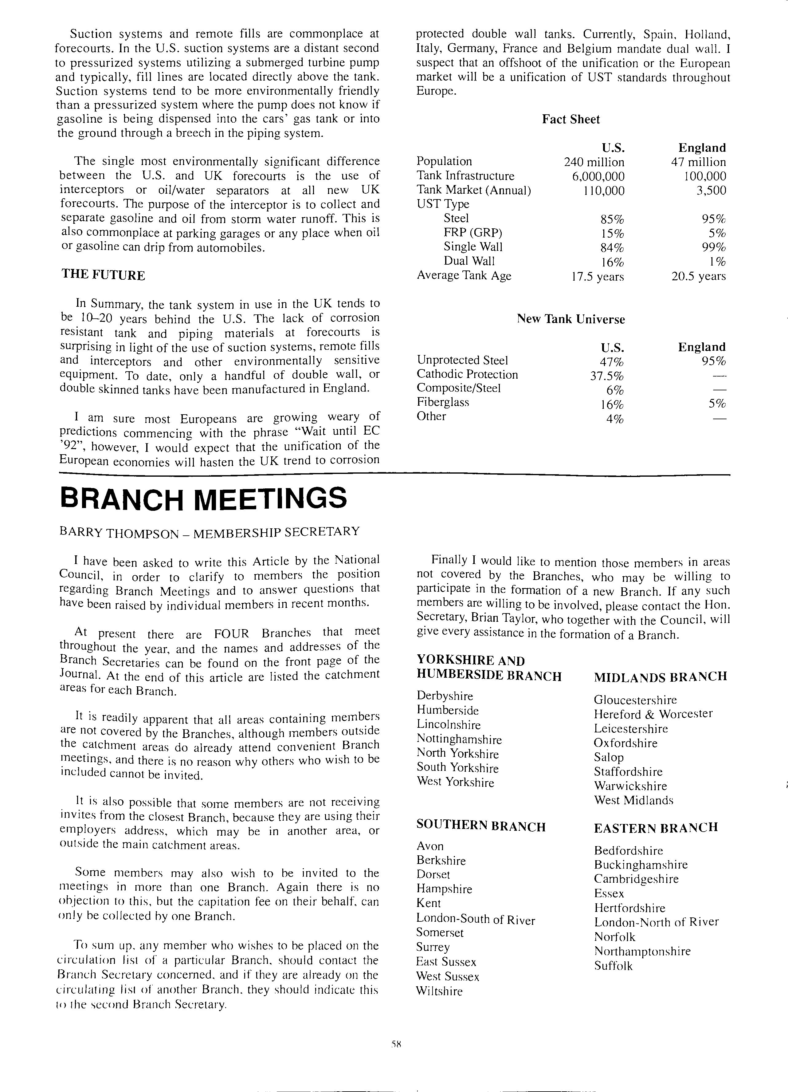
protected double wall tanks. Currently, Spain, Holland, Italy, Germany, France and Belgium mandate dual wall. I suspect that an offshoot of the unification or the European market will be a unification of UST standards throughout Europe.
Fact Sheet
Population Tank Infrastructure Tank Market (Annual) UST Type Steel FRP (GRP) Single Wall Dual Wall Average Tank Age
U.S. 240 million 6,000,000 110,000 85% 15% 84% 16% 17.5 years
New Tank Universe
Unprotected Steel Cathodic Protection Composite/Steel Fiberglass Other
U.S. 47% 37.5% 6% 16% 4%
England 47 million 100,000 3,500 95% 5% 99% 1% 20.5 years
England 95% 5%
Finally I would like to mention those members in areas not c?vere? by the Branches, who may be willing to part1c1pate m the formation of a new Branch. If any such members are .willing to be involved, please contact the Hon. Bnan Taylor, who together with the Council, will give every assistance in the formation of a Branch.
YORKSHIRE AND HUMBERSIDE BRANCH
Derbyshire Humberside Lincolnshire Nottinghamshire North Yorkshire South Yorkshire West Yorkshire
SOUTHERN BRANCH
Avon Berkshire Dorset Hampshire Kent London-South of River Somerset SmTey East Sussex West Sussex Wiltshire
MIDLANDS BRANCH
Gloucestershire Hereford & Worcester Leicestershire Oxfordshire Sal op Staffordshire Warwickshire West Midlands
EASTERN BRANCH
Bedfordshire Buckinghamshire Cambridgeshire Essex Hertfordshire London-North of River Norfolk Northamptonshire Suffolk
'i8
New Members
 The Association welcomes the following new members
Gordon Robb Highland Regional Council
Andrew Coe J Sainsbury pie
Western Welding & Engineering Co. Ltd.
Johanne Kelly 'Forecourt Trader'
David Pounds
Frank Hare Poslec Developments Ltd
John Wright Poslec Ltd
Mr Andrew Swan Dunclare Dispensers (UK) Ltd
R L Weeks 'Byways' Brockenhurst Road
Mrs Morag Clewes Texaco Ltd
GR Bryant Central Electrical Installation Limited
Andrew James Renals
Cornwall County Fire Brigade
Nicholas Western Kuwait Petroleum International
Derek Painter Essex County Council
MR Weston Faithful Gould
Charles Stephen Handley Burmah Petroleum Fuels
R. H. Prichard Conoco Ltd (Jet)
Frederick CR Neaves
John Waller Shell UK Oil
Vincent Coughlin
Mr John Suesse JFS Forecourt Installations Ltd
The Association welcomes the following new members
Gordon Robb Highland Regional Council
Andrew Coe J Sainsbury pie
Western Welding & Engineering Co. Ltd.
Johanne Kelly 'Forecourt Trader'
David Pounds
Frank Hare Poslec Developments Ltd
John Wright Poslec Ltd
Mr Andrew Swan Dunclare Dispensers (UK) Ltd
R L Weeks 'Byways' Brockenhurst Road
Mrs Morag Clewes Texaco Ltd
GR Bryant Central Electrical Installation Limited
Andrew James Renals
Cornwall County Fire Brigade
Nicholas Western Kuwait Petroleum International
Derek Painter Essex County Council
MR Weston Faithful Gould
Charles Stephen Handley Burmah Petroleum Fuels
R. H. Prichard Conoco Ltd (Jet)
Frederick CR Neaves
John Waller Shell UK Oil
Vincent Coughlin
Mr John Suesse JFS Forecourt Installations Ltd
SEMINAR 1990
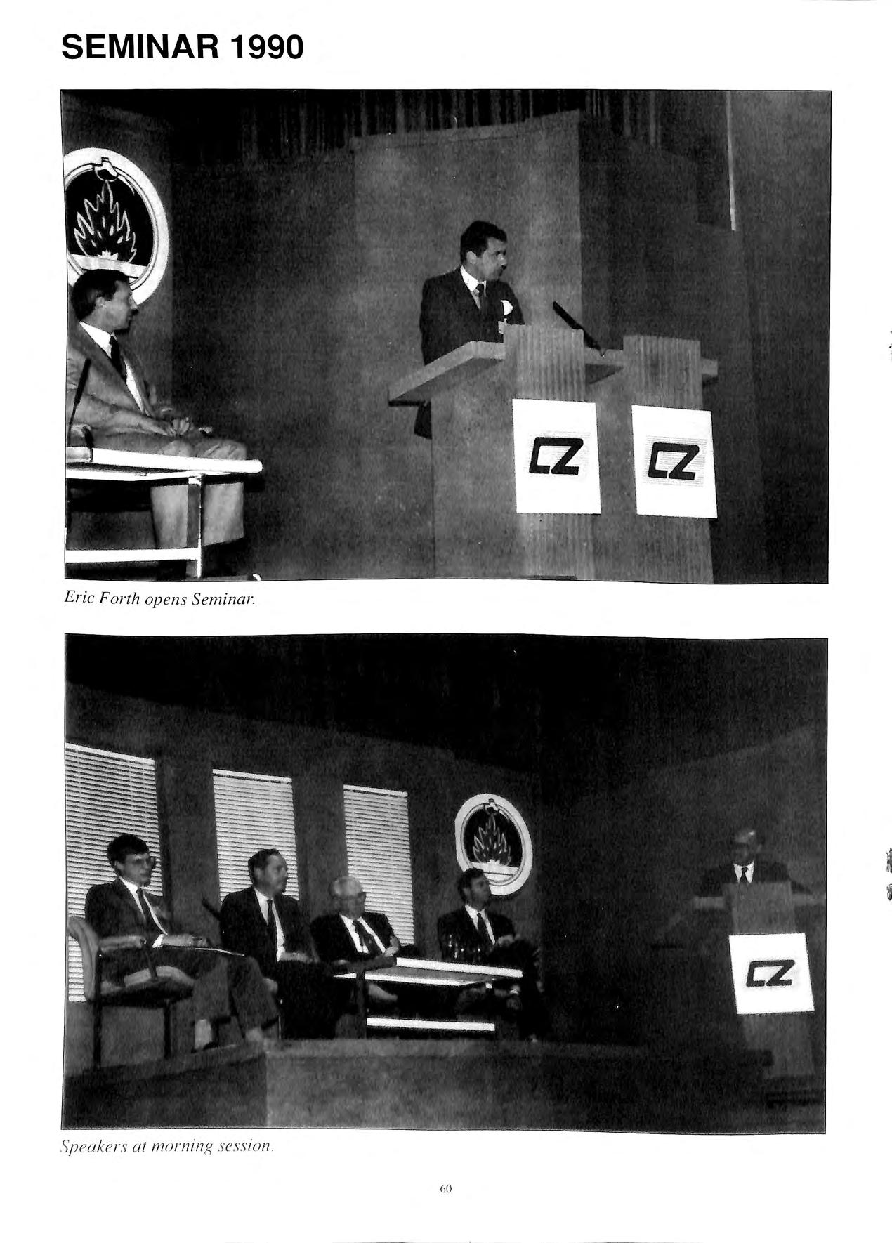 Eric Forth opens Seminar.
60
S peaker s al morn i ng sess i on
I '
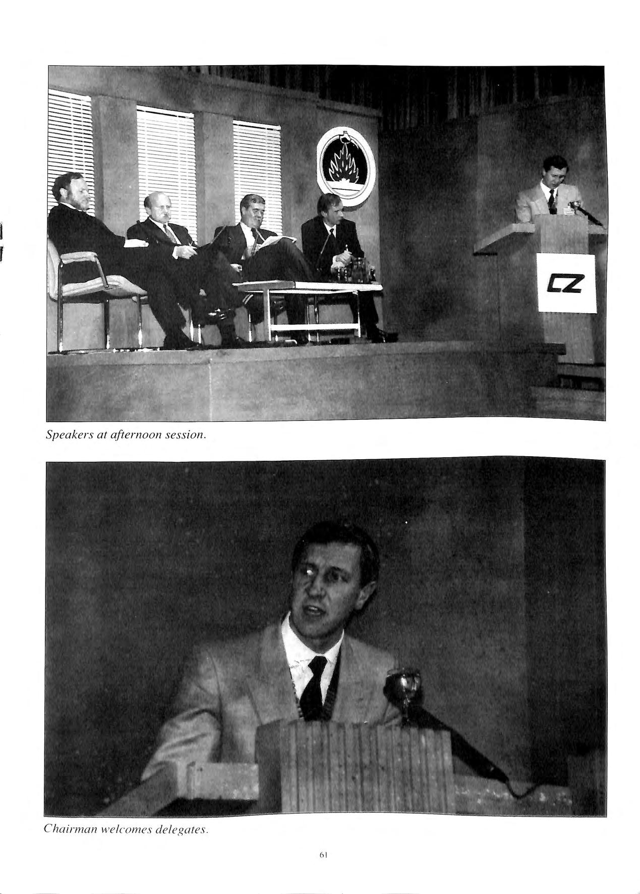
Speakers at afternoon session.
61
Cha irman welcomes delegates.
Rick Smi t h of Redja c k e t RAVENA CONSTRUCTION LTD Building & Civil Engineering Contractors Specialists in all forms of forecourt petroleum installations FOR FREE QUOTE TELEPHONE: 0926 624489 (Office) or 0831 461061 (Mobile) The WiHow Tree, Wa sperton, Barford, Warwick, CV35 8EB h2
an Underground Storage Tank and Product Handling System
Presented at the APEA Seminar, October 2, 1990 by George S. Lomax, Technical Services Manager, Heath Consultants Inc., Stoughton, Massachusetts, U.S.A.
Testing an underground storage tank and product handling system begins with a good general knowledge of the storage system being tested, the environment in which the system operates, and the test method employed. This paper will address problem areas related to the mechanics of an underground storage system, environmental factors that affect tank volume during an integrity test, and the necessary components of a valid tank tightness test.
DEFINITION OF TERMS
Throughout this paper any reference to a tank or tank system includes the buried tank, all connected piping, the pump system, and any other associated components that contain or may contain product. In addition, the usage of the terms tightness test, integrity test, or precision test, all relate to the same procedure, unless otherwise indicated.
THE PERFECT TANK
To better understand some of the problems encountered with the mechanical components of a tank system, it is necessary to review selected components of what would be considered the perfect tank.
Entrapped vapor or air anywhere in a tank system can be a major cause of inaccurate test results. The perfect tank should be level and have an opening to the vent line or fill pipe at either end to prevent the entrapment of any volume of air or vapor. This would also allow any amounts of air or vapor that could remain in the tank, after fill up, to go to atmosphere.
If there is a man way on the tank, it should be accessible and have a valve or threaded plug that would allow entrapped air or vapor to be vented during the fill up for testing.
Piping connected to the tank should be installed according to sound engineering practices. The vent and product lines should have a gradual upward slope from the tank to the point at which they enter a building or come above grade. This type of installation prevents the entrapment of air or vapor during the fill up for testing.
Installation of the tank in the excavation and the type of back-fill material should also be considered. The vertical center line of the tank should be perpendicular to grade: If the tank is allowed to roll or pitch off of placement into the excavation. all the associated p1pmg will be affected. Openings on the tank will no longer be at top dead center; causing entrapment of air or vapor in the upper atmosphere of the tank.
For U.S. design tank systems, specific back-fill materials are required depending on the design of the tank system. When installing a steel tank. or fiberglass clad steel tank.
washed pea gravel or sand is required as fill material. For tanks, only washed pea gravel is allowed by the vanous manufactures as back-fill material. Proper compact1on of the backfill is most critical for adequate structural support of the tank after installation. Here in the United Kingdom concrete has been the prefered back-fill material for your tank system designs. The concrete offers excellent structural support for the tank system.
Other components of the perfect tank and associated piping would be site or monitoring wells for determination of the water level around the tank and for leakao-e inspection, cathodic protection on all buried steel used in the system, and in some environmentally sensitive areas double wall construction. Monitoring or release equipment such as automatic tank gauging systems, vapor and liquid product sensors in monitoring wells and double wall tanks are also desirable.
A problem with almost all existing facilities is lack of documentation on the tank system. The perfect tank system would have a complete set of diagrams on the location and layout of the tank system a complete listing of the materials used in the construct10n of the system.
THE NOT SO PERFECT TANK
The not so perfect tank is often found in the real world. Industrial tank systems seem to have more problems than retail petroleum tank systems. Here are some of the problems frequently encountered.
Information on tank capacity, location, and details on the associated piping sometimes are not available. If there are any drawings or diagrams on the system, they are either design prints or plans and not as built final d.iagrams. If any diagrams or prmts are at. the locat1on, they have probably not smce mstallation. It is often the case at an that the tank to be tested isn't even located where md1cated on company drawings.
is in the tank or connected to the tank that operating personnel or the tester should know'J Me h· · 1 · C dl11Ca components. check v.alves. buned manways, welded drop tubes, and gauge Imes may all cause a probl 111 · 1·d · h em perfonrnng a va 1 t1g tness test.
A tank may have been used for stor·toe ol' i · ' e one proc uct taken out of service for a while: and put ba 'k · t . . "· · · d.ft· l 111 o se1 vice conta111111g a 1 erent 1Jroduct Res1.liti·tl 1111 t 1· 1 t · · OU n S O t 1e prev10us material may have formecl ·i l·iyei· t· ·l d TI · ' ' o s u oe. 11s layer ot sludge can have an adverse effect on the r:..,ults of the test.
Was this tank properly installed? In the first section of this paper; the perfect tank and the proper way to install a product handling system is discussed. When evaluating a system for testing, it is important to keep in mind the properties of a good tank installation in order to determine the status of an existing system. An indication of potential problems would be the overall settling of the concrete or asphalt pad and surrounding excavation area of the fuel handling system. This settling of improperly compacted back-fill material will cause a number of problems with the system.
The tank may be out of "round" due to loss of support from the fill material. This will change the volume in the vessel. Piping connected to the tank will be under mechanical stress due to subsidence of the ditch wall and fill area causing a swag in the product and vent lines, and possibly mechanical failure. The swag in the product or vent lines may result in the entrapment of air or vapor during testing.
Other considerations when evaluating a system for testing are the location of the fill pipe and access points, the presence of a buried manway, and the tilting of the tank on either the vertical or lateral axis. If the tank has two access points, a fill pipe and manway, for example, the inclination of the tank can be checked providing there is an amount of water in the bottom of the tank. Using water finding paste on a gauging stick, check the detected water level at both openings. If the measurement is the same, or near the same in both openings, the tank is near level.
A plumb line can be dropped into the fill pipe to determine if the fill pipe is vertical. If the fill pipe does not appear to be vertical, either the tank is tilted on the vertical axis or the fillpipe may have been struck and bent. This possible damage may be a source of leakage.
THE PHYSICAL PROPERTIES OF AN UNDERGROUND STORAGE SYSTEM AND SELECTED CONTENTS
Assuming the tank and associated p1pmg is properly instaled, the physical properties of the tank and contents, as well as the surrounding environment, is the next area of discussion. For purposes of simplification, gasoline will be used as the reference material.
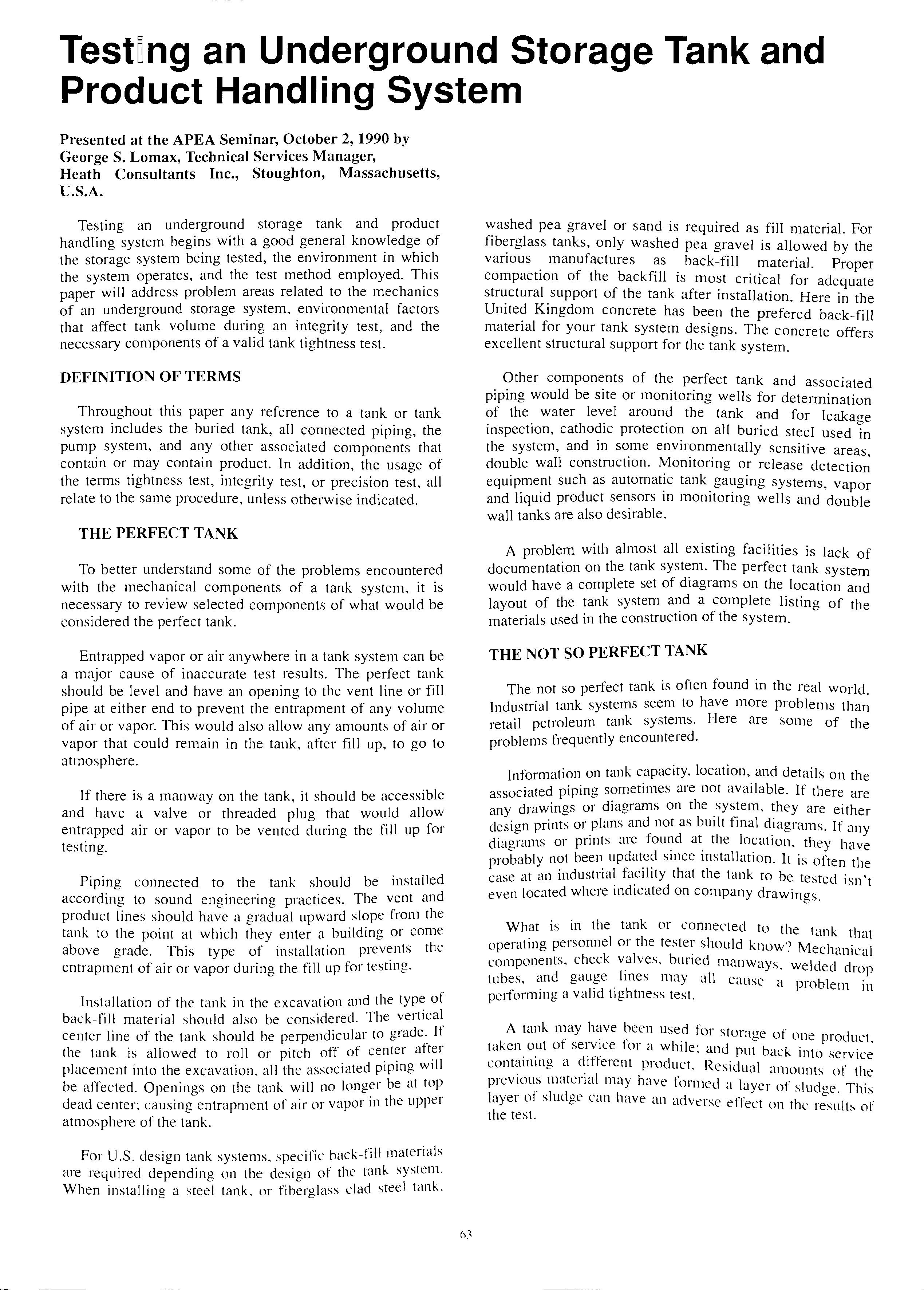
As mentioned in the first section of this paper, the use of proper backfill material and the correct compaction of this backfill is important to afford structural support to the tank and associated piping. This is necessary to minimize structural deformation of the tank. However, the tank, when properly installed, will change shape and volume due to pressures brought to bear on the inner and outer walls. As a steel tank is subjected to the cyclical loading and removal of product, the tank ends will deflect outward and then again inward. This is referred to as tank end deflection. (See table I)
APPARENT LOSS OF PRODUCT VOLUME DUE TO FORCE ON TANK ENDS-IN GALLONS END DEFLECTION IN INCHES TANK 2.93 48" .498 .98 1.47 1.95 2.44 I I I I I I I I I I I I I I I I I 34;. NINE "B" "A" PROBABLE LIMIT OF TANK END DEFLECTION CAPACITY INCREASE " '-' B"
OF
TANK END DEFLECTION CAPACITY
64" 72" 76• 64• 120" 126" .872 1.74 2.61 1.101 2.20 3.31 1.227 2.46 3.68 1.50 3.00 .(50 1.957 3.91 5.87 2.21 4.42 6.65 3.06- 6.12 4.41 4.91 6.00 7.62 865 5.22
8.97 6.02
6.12 7.36
7.50 ..,,
12.00 9.n 11.75 15.65 11.06 13.30 15.50
19.57
' 12.25 15.30 18.38 21.40 24.50-L 3670 260 4900 I " I'\ · 4 ·
· 3.37 6.75 10.12 13.00 16.85 20.3 23.8 27.0
40.5 47.2 54.0 80.7 MAXIMUM DEFLECTION FIGURES ARE PRELIMINARY BASED ON LIMITED DATA FROM TANK MANUFACTURERS AND COMPLETELY FLUID SOIL CONDITIONS MEASUREMENTS WERE MADE WITH AIR PRESSURE ABOVE GROUND
Table
Apparent Loss of Product Volume (4) Due lo Force on Tank Ends In Gallons
Petro
Tank
Bulletin 64
LIMIT
MAXIMUM
INCREASE
8.10
1.12 0.02
8.60 9.81
10.50
'\.70 11.01 12.27 15.00
22.20 18.00 23.50 28.60
,_____
,33.75
l/io" 1;.•
I
Ref: Heath Consultants, Inc.,
Tite
Tester
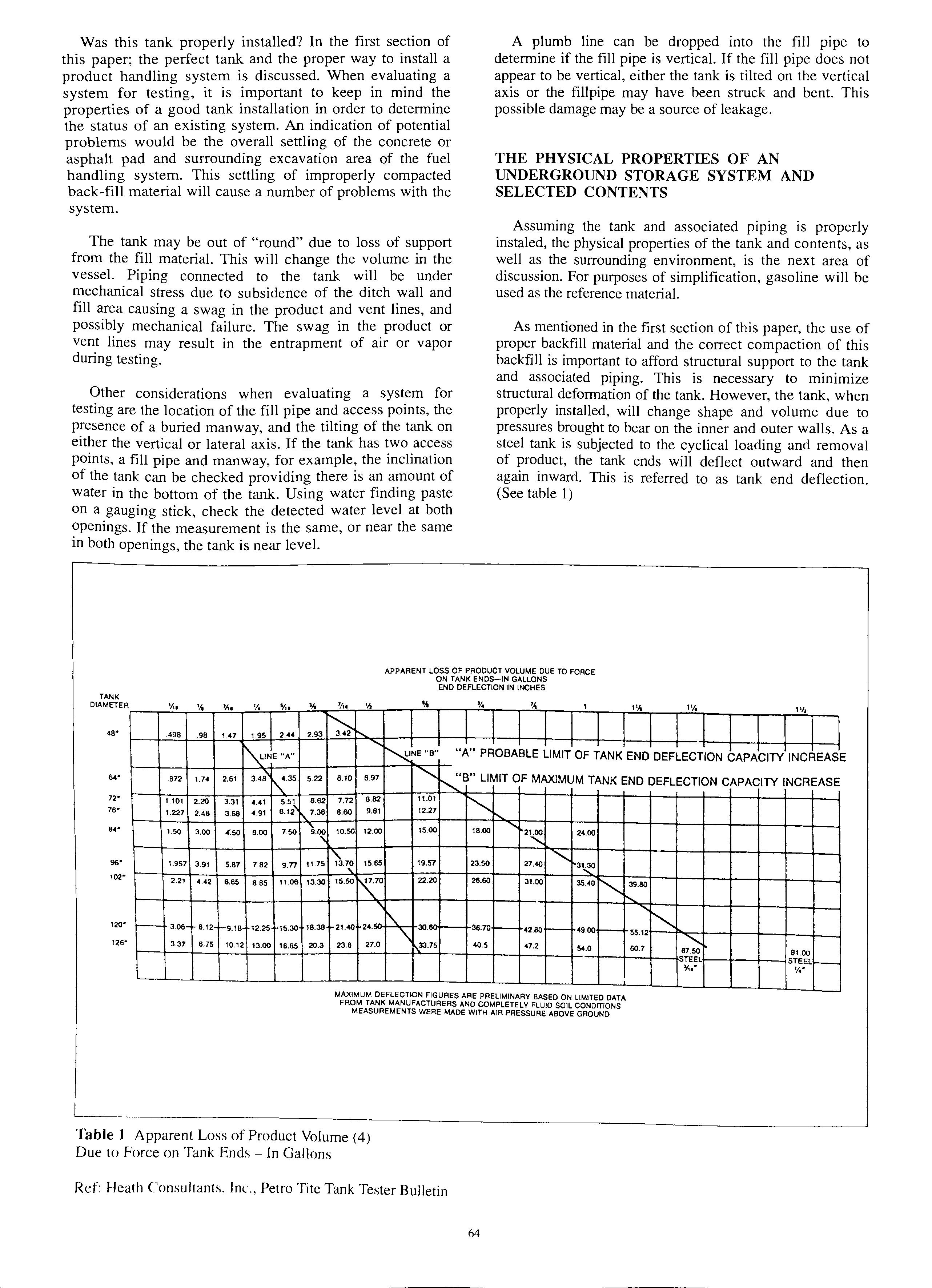
Fig. 1 Tank End Deflection (4)
Ref: Heath Consultants, Inc. Petro Tite Tank Tester Bulletin
On the other hand, a fiberglass reinforced plastic tank will not experience the tank end deflection of a steel tank due to the design of the end caps. It will, however, experience expansion of the side walls over the entire vessel. The expansion of either a steel or fiberglass reinforced plastic tank during the tank test will result in an observed loss of product. (See figure 1)
External pressure on the outer wall of the vessel can be a result of subsurface water or a high water table exerting a counter force. The effects of this external counter force will be discussed in greater detail in the section on tank test procedures.
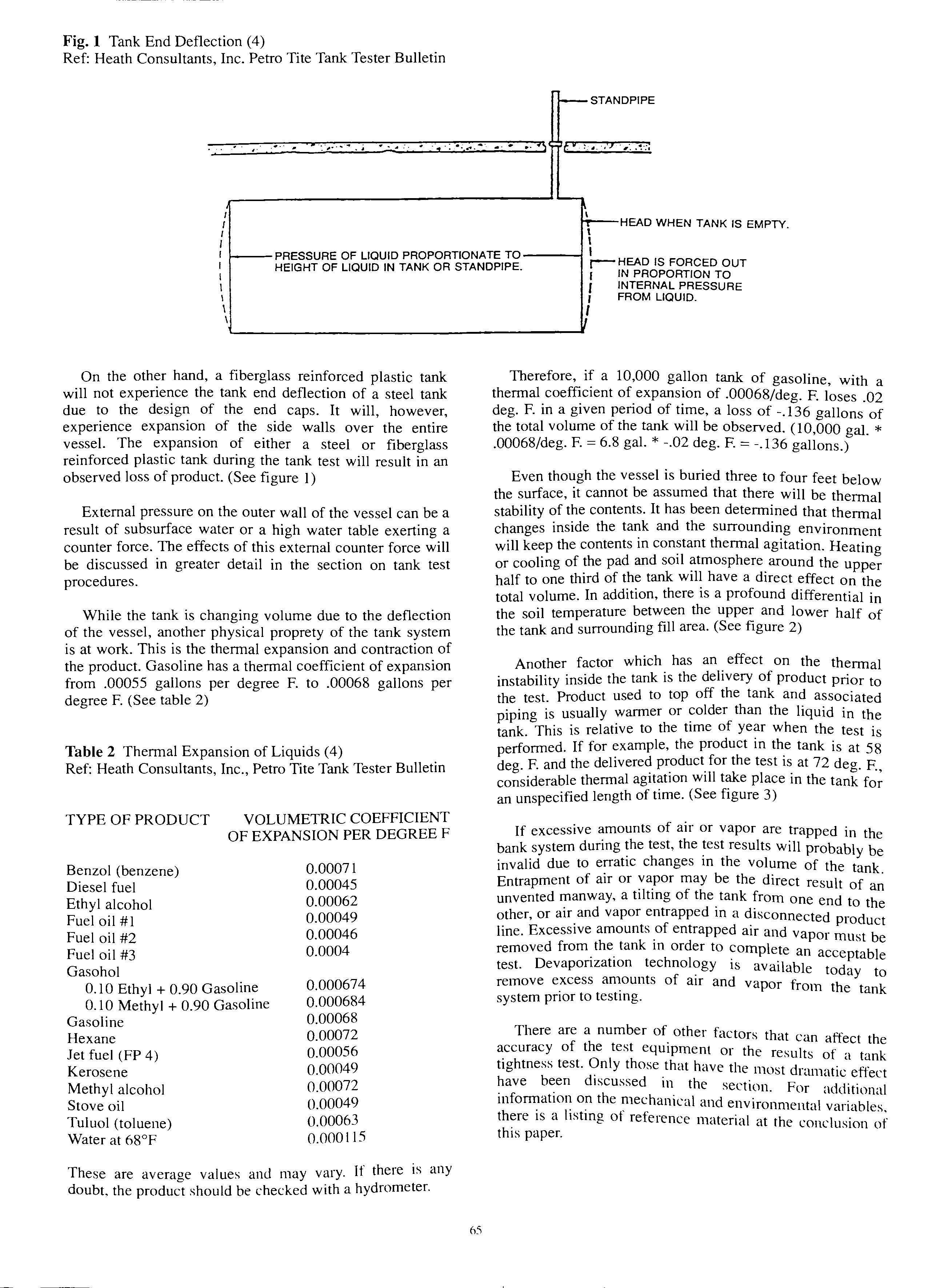
While the tank is changing volume due to the deflection of the vessel, another physical proprety of the tank system is at work. This is the thermal expansion and contraction of the product. Gasoline has a thermal coefficient of expansion from .00055 gallons per degree F. to .00068 gallons per degree F. (See table 2)
Table 2 Thermal Expansion of Liquids (4)
Ref: Heath Consultants, Inc., Petro Tite Tank Tester Bulletin
TYPE OF PRODUCT VOLUMETRIC COEFFICIENT OF EXPANSION PER DEGREE F
Benzol (benzene)
Diesel fuel
Ethyl alcohol
Fuel oil #1
Fuel oil #2
Fuel oil #3
Gasohol
0.10 Ethyl + 0.90 Gasoline
0.10 Methyl + 0.90 Gasoline
Gasoline
Hexane
Jet fuel (FP 4)
Kerosene
Methyl alcohol
Stove oil
Tuluol (toluene) Water at 68°F
0.00071 0.00045 0.00062 0.00049 0.00046 0.0004 0.000674 0.000684 0.00068 0.00072 0.00056 0.00049 0.00072 0.00049 0.00063 0.000115
These are average values and may vary. If there is any doubt, the product should be checked with a hydrometer.
I IN PROPORTION TO f INTERNAL PRESSURE I FROM LIQUID. I
Therefore, if a 10,000 gallon tank of gasoline with thermal. of_ expansion of .00068/deg. F. .O; deg. F. m a given penod of time, a loss of -.136 gallons of the total of the will be observed. (I 0,000 gal. * .00068/deg. F. 6.8 gal. -.02 deg. F. = -.136 gallons.)
Even though the vessel is buried three to four feet below the surface, it cannot be assumed that there will be thermal stability of the contents. It has been determined that thermal changes inside the tank and the surrounding environment will keep the contents in thermal agitation. Heating or cooling of the pad and soil atmosphere around the upper half to one third of the tank will have a direct effect on the total volume. In addition, there is a profound differential in the soil temperature between the upper and lower half of the tank and surrounding fill area. (See figure 2)
Another factor which has an effect on the thermal instability inside the tank is the delivery of product prior to the test. Product used to top off the tank and associated piping is usually warmer or than the liquid in the tank. This is relative to the time of year when the test is performed. If for example, the product in the tank is at 58 deg. F. and the pr_oduct_ for the test is at 72 deg. F., considerable thermal ag1tat10n will take place in the tank for an unspecified length of time. (See figure 3)
If excessive of air or vapor are trapped in the bank system durmg test, the results will probably be invalid due to changes m the volume of the tank. Entrapment of air or vapor may be the direct result f ·1. f h o an unvented manway, a t1 tmg o t e tank from one end t h . d t d. ot e other, or air an vapor en rappe 111 a disconnected . d . . f p10 uct hne. Excessive amounts o entrapped air and vapo. b . e removed from the tank m order to complete an acceptab le test. Devaponzat1on technology is availabl t d . e o ay to remove excess amounts of air and vapor fr h · om t e tank system pnor to testmg.
There are a number of other factors that ,,. · can auect the accuracy of the test eqmpment or the . 1 . f . . . resu ts o a tank tightness test. Only those that have the 1110 ·t d · ff' s ramat1c e ect have been discussed 111 the secti'cJn F d :1· . · or a c 1t1onal the and environmental variables, there 1s a hstmg of reference m·iteri·al at th 1 , , e cone us10n of this paper.
STANDPIPE _._ ·• •.;:.. :. .•.••. t•.: 'J· ' I HEAD WHEN TANK IS EMPTY. I I I I I PRESSURE OF LIQUID PROPORTIONATE T0----1 I HEIGHT OF LIQUID IN TANK OR STANDPIPE. r-- HEAD IS FORCED OUT I I \ \ I \
65
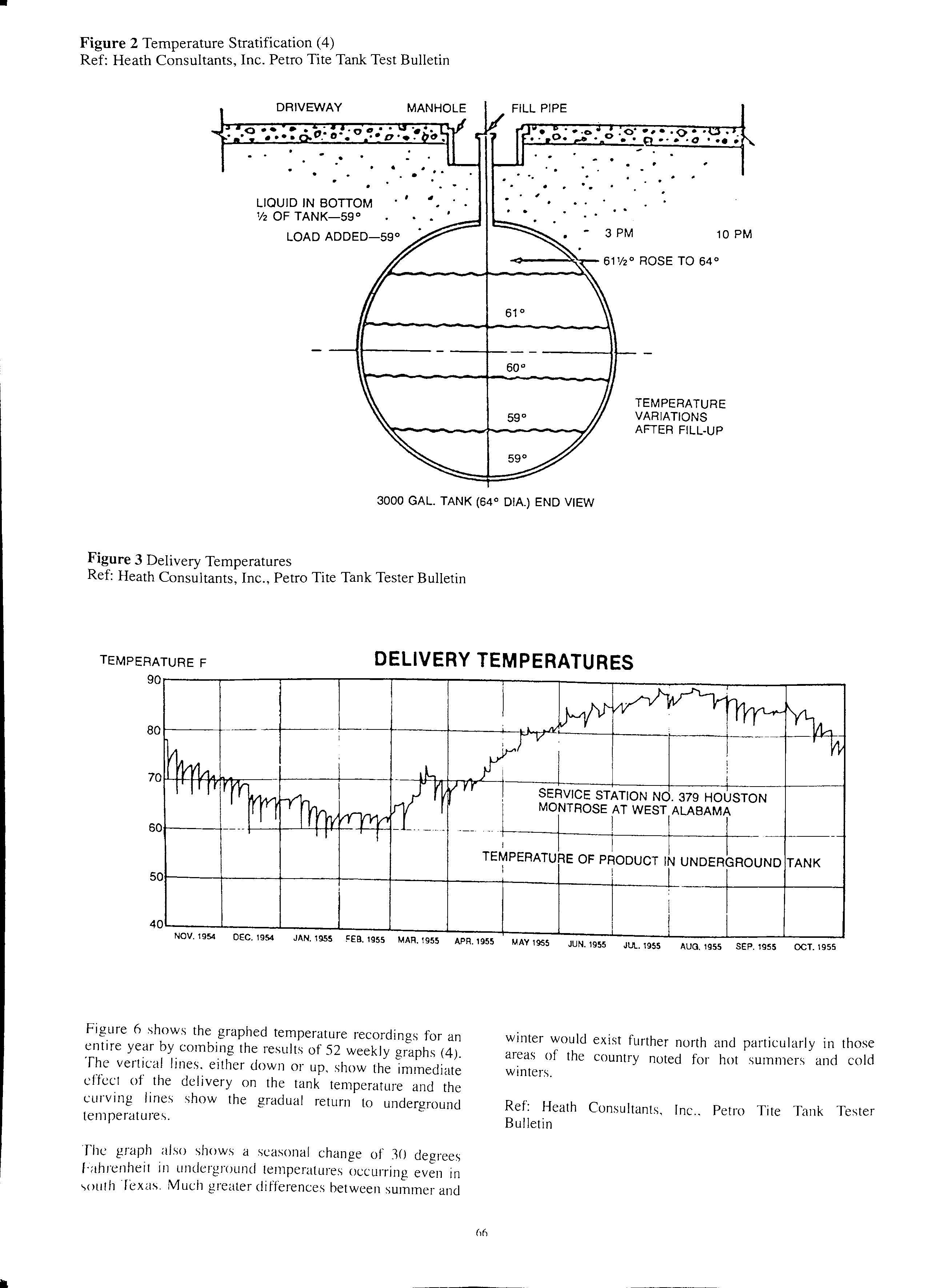
Figure 2 Temperature Stratification (4)
Ref:
Tite
Ref: Heath Consultants, Inc., Petro Tite Tank Tester Bulletm
Figure 6 shows the graphed temperature recordings for an entire year by combing the results of 52 weekly graphs (4). The vertical lines. either down or up, show the immediate effect of the delivery on the tank temperature and the curving lines show the gradual return to underground temperatures.
The graph also shows a seasonal change of 30 degrees Fahrenheit in underground temperatures occurring even in -, 0 uth ·rexas. Much greater differences between summer and
winter would exist further north and particularly in those areas of the country noted for hot summers and cold winters.
Ref: Heath Consultants, Inc.. Petro Tite Tank Tester Bulletin
•
Heath Consultants, Inc. Petro
Tank Test Bulletin LIQUID IN BOTTOM 1/2 OF TANK-59° LOAD ADDED-59° MANHOLE FILL PIPE -3 PM 10 PM TEMPERATURE VARIATIONS AFTER FILL-UP 3000 GAL. TANK (64° DIA.) END VIEW Figure 3 Delivery Temperatures .
TEMPERATURE
80t-----r 60r---, I SERVICE STATION NO. 379 HOUSTON MONTROSE AT WEST ALABAMA I TEMPERATURE OF PRODUCT IN UNDERGROUND TANK I I 501----+----+---t-----11----+----+----+---+----l----+----t-----; NOV. 1954 DEC. 1954 JAN. 1955 1955 MAR. 1955 APR. 1955 MAY 1955 JUN. 1955 JUL. 1955 AUG. 1955 SEP. 1955 OCT. 1955
DELIVERY TEMPERATURES
F
66
TANK TESTING PROCEDURES
It is most important that when performing a volumetric test of an underground storage tank system that we follow a specific test protocol. This protocol must be specified in writing for manual testing and also be part of any data base used to operate a computerized testing system. With only two exceptions, no deviations from a written test protocol are acceptable. These are:
1. The test may be terminated prematurely in the event of a gross leak being detected early on during the test.
2. The test protocol may be extended to accomodate unusual fluxuations in temperature that would be observed during the test.
The written protocol and the physical equipment used to test a tank system should take into consideration all the variables discussed in the previous section to produce a valid tank system test. Persons performing the test must be trained and qualified in the proper operation of the testing equipment.
Before the commencement any work at the location, safety of the job site must be our first priority. The tank area must be isolated from all vehicle movement with barricades, safety cones, or construction tape. Often a testing contractor will place the service van directly in the path of normal vehicular movement, especially if the driveway or access to the dispensers is directly over the tanks.
Any vehicles in the work area must be removed. If a tanker truck is in the process of topping off the tank systems for testing, no work activity can begin until the tanker truck has completed filling the tanks and has left the station.
A minimum of two approved fire extinguishers must be available at all times to testing and fire safety personnel. The placement of these fire extinguishers at the job site is critical. Only certified testing personnel and fire safety personnel are allowed in the work area.
Prior to arrival at the work site, arraignments need to be made by the tank owner or the contractor for fill up of the tanks to be tested. Testmg personnel should make every attempt to be at. th.e while the delivery tanker is filling the tanks. This 1s for safety reasons and to insure that the delivery truck dnver leaves the tanks as full as possible for testing.
Once the tanker truck has left the job site and the work · d J'or sa"ety reasons testing personnel can area 1s secure I' ' • begin the process of inspecting the tank system for h · 1 blems that may need to be addressed. All mec amca pro · ·.· , 1 control anel dispensers must be turned off at th.e elect11ca . . P and locked out of service at the island. At this time they · "th the station operator will usually commumcate w1 · regarding the necessary infonnation required for documentation prior to testing.
There are two primary means of testing a tank syste.m. Both technologies employ a volume measurement device and a temperature measurement system. Dependmg on the viscosity of the product contained in the tank.. we must choose between a tester intended for heavy liquids such as heating and lubrication oils, or a tested intended for use
with motor and aviation fuels. The testing system used with the lighter liquids uses a circulating system for temperature control. A tester used for the heavier liquids cannot circulate the liquid and must therefore test the product in a static temprature stabilized condition.
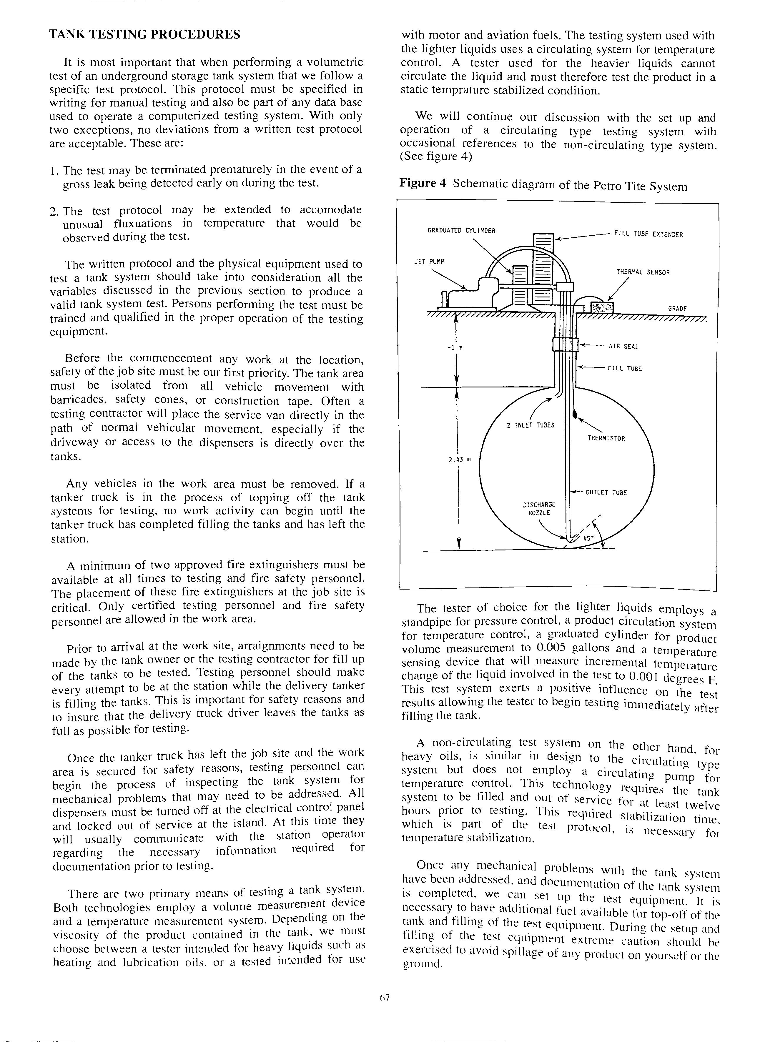
We will continue our discussion with the set up and operation of a circulating type testing system with occasional references to the non-circulating type system. (See figure 4)
Figure 4 Schematic diagram of the Petro Tite System
The tester of choice for the lighter liquids employs a standpipe for pressure control, a product circulation system for temperature control, a graduated cylinder for product volume measurement to 0.005 gallons and a temperature sensing device. :Viii incremental temperature change of the hqu1d mvolved m the test to 0.001 deorees F b • This test exerts a on the test results allowmg the tester to begm testmg immediately after filling the tank.
A non-circulating test system on the other h· d t· ·1 ·1 d . dn 01 heavy 01 s, 1s sum ar 111 es1gn to the c 11·ctil·dt.mg type system but does not employ a circuhtino t' •• < <=- pump or tempe1 dture control. This technolooy 1·equ11-e. tl •• • <=- s 1e tank system to be filled and out o1 service for ·it I ·t 1 c eas twe ve hours pnor to testmg. This reL\uired stabi·1· t. · • c 1zc1 ion tune which 1s part of the test protocol is ne f' · b .1. · • · cessc11y or temperature sta 1 1zat1on.
Once any mechanical problems witl1 tl1 t k · e an system have been addressed. and document·1t1·011 ot· tl t k . . . " ' 1e an · system 1s completed. we can set up tl1e test eq · I · · rnpment. t 1s necessary ,add1t1onal fuel available for top-off of the tank and h \ling ot the test ec1uipment. During tl . t . l .. 1I' , f l . . 1e se up dill 11 o t 1e test equipment extreme caution should he exercised to avoid spillage of any product 011 yourself or the ground.
67
·l m AIR SEAL -<--FILL TUBE 1 THERMISTOR 2. m
During the set up and filling of the equipment, testing personnel should observe for any unusual conditions gross leakage. If the tank is located in a high water table and water is known to be around the tank, it will be necessary to elevate the standpipe in order to compensate for the effects of this water table on any detectable flow rate or leak in the tank. (See figure 5)
After the equipment is set up on the tank and filled with product, the electrical connections can be made. It will be necessary to turn the circulating pump on and off a couple of times to cycle any additional vapor out of the tank and test equipment. Once this is completed the circulating system is turned on and the test can begin.
At the beginning of this section of the paper, we discussed the importance of a specific test protocol. Here is a complete summary of the protocol requirements for a 6,000 gallon tank filled with gasoline:
Test Phase #1, Pre-circulation.
This test phase is based on the total volume of the tank. The circulation time is 5 to 8 minutes per thousand gallons based on the viscosity of the liquid. For example, 6,000 gallons of gasoline will be circulated for a minimum of 30 minutes. Whereas, 6,000 gallons of diesel fuel will be circulated for a minimum of 48 minutes.
This circulation time can be extended, often testing personnel will leave the pump system to circulate while they inspect for obvious leaks in the equipment and the tank or while they clean up the work area and return nonessential tools to the service vehicle. During this test phase the standpipe is kept at maximum product level, above 42".
Test Phase #2, Density Calculations.
At the conclusion of test phase #1, a sample of circulated product is removed from the tank. A thermometer and hydrometer for petroleum products are placed in the sample and allowed to temperature stabilize. A reading of the temperature and the density is then taken and recorded on the data chart. A calculation is then made to determine the thermal coefficient of the liquid involved in the test. This number is then used throughout the test to convert all temperature measurements to volume. This test phase usually takes no more than fifteen to twenty minutes.
Test Phase #3, High Level Test.
Test phase #3 is actually a pre-test of the tank system. The product level in the standpipe is maintained at exactly 42" and precise measurements of the observed volume and change are recorded. The length of time requlfed for test phase #3 is based on the diameter of the (See table 3) For a 6,000 gallon tank that is 96" in test phase #3 will consist of minimum of 8 fifteen mmute readings or two hours.
During test phase #3 specific temperature and volume trends are anticipated for validation of the test. If temperature volume trends are irratic, testing personnel must determme source of the problem and eliminate it. Problems may anse from improper circulation or the presence of a large air/vapor pocket. If a consistent detectable flow. rate is observed, it behooves the test operator to termmate the test as this is usually evidence of a leak.
If there is no obvious leaks in the tank system, and temperature and volume trends are consistent, the tester may proceed to test phase #4.
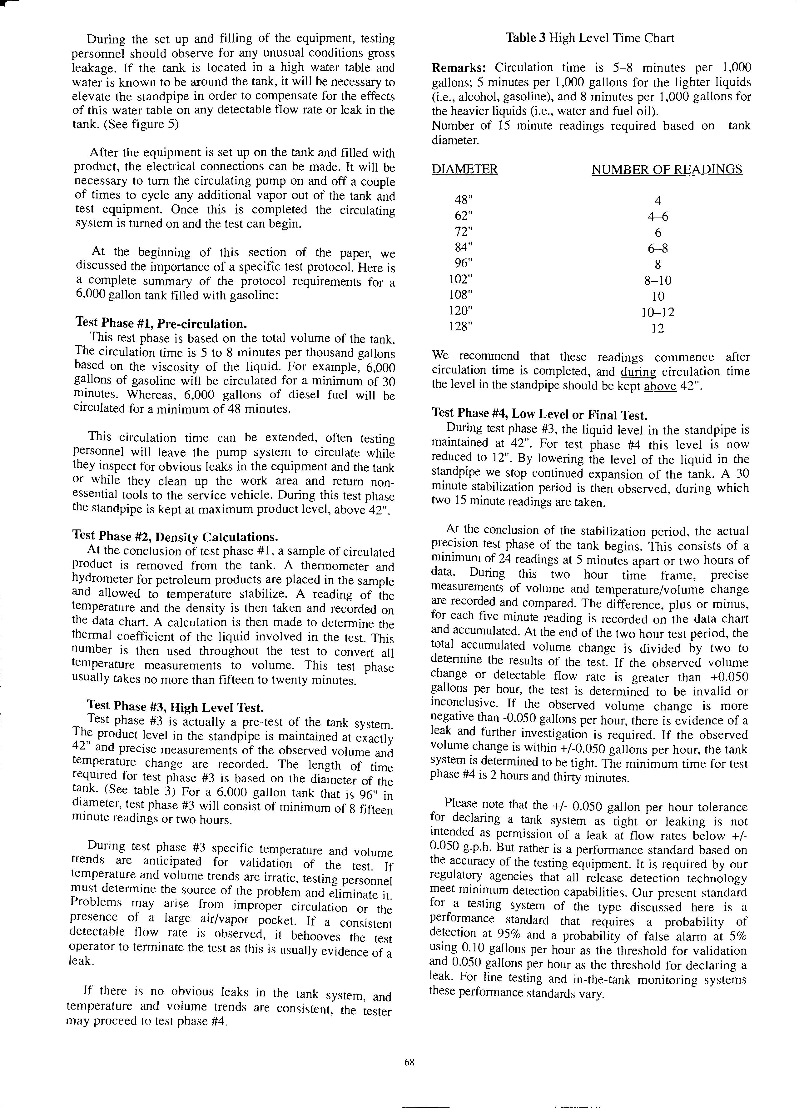
Table 3 High Level Time Chart
Remarks: Circulation time is 5-8 minutes per 1,000 gallons; 5 minutes per 1,000 gallons for the lighter liquids (i.e., alcohol, gasoline), and 8 minutes per 1,000 gallons for the heavier liquids (i.e., water and fuel oil).
Number of 15 minute readings required based on tank diameter.
DIAMETER
NUMBER
OF
READINGS 48" 4 62" 4-6 72" 6 84" 6-8 96" 8 102" 8-10 108" 10 120" 10-12 128" 12
We recommend that these readings commence after circulation time is completed, and during circulation time the level in the standpipe should be kept above 42".
Test Phase #4, Low Level or Final Test. During test phase #3, the liquid level in the standpipe is maintained at 42". For test phase #4 this level is now reduced to 12". By lowering the level of the liquid in the standpipe we stop continued expansion of the tank. A 30 minute stabilization period is then observed, during which two 15 minute readings are taken.
At the conclusion of the stabilization period, the actual precision test phase of the tank begins. This consists of a minimum of 24 readings at 5 minutes apart or two hours of data. During this two hour time frame, precise measurements of volume and temperature/volume change are recorded and compared. The difference, plus or minus, for each five minute reading is recorded on the data chart and accumulated. At the end of the two hour test period, the total accumulated volume change is divided by two to determine the results of the test. If the observed volume change or detectable flow rate is greater than +0.050 gallons per hour, the test is determined to be invalid or inconclusive. If the observed volume change is more negative than -0.050 gallons per hour, there is evidence of a leak and further investigation is required. If the observed volume change is within +/-0.050 gallons per hour, the tank system is determined to be tight. The minimum time for test phase #4 is 2 hours and thirty minutes.
Please note that the +/- 0.050 gallon per hour tolerance declaring a tank system as tight or leaking is not mtended as permission of a leak at flow rates below +/0.050 g.p.h. But rather is a performance standard based on the accuracy of the testing equipment. It is required by our regulatory agencies that all release detection technology meet minimum detection capabilities. Our present standard for a testing system of the type discussed here is a performance standard that requires a probability of at 95% and a probability of false alarm at 5% usmg 0.10 gallons per hour as the threshold for validation and 0.050 gallons per hour as the threshold for declaring a leak. For line testing and in-the-tank monitoring systems these performance standards vary.
68
6).4" correct elevat1on to 12" level
195.4" Total He1gh
Tank bottom to grade ·level
1. Locate the water table in reference to the tank bottom.
2. Calculate the pressure exerted by the water on the tank bottom. 30" x .036 = 1.08 psi
3. Add the 4 psi to determine the internal liquid pressure. 1.08 psi + 4.00 psi = 5.08 psi
4.Calculate the total height from the tank bottom. 5.08 psi 195.4" .026
5. Determine the height of the stand-pipe above grade to the 12" level. 96" + 36" = 132"
(Total height) (Tank bottom to grade) = Elevation to the 12" level 195.4 132" = 63.4"
6. The height of the stand-pipe above grade to the 12" mark is 63.4"
Note: Certain high level elevations may slightly exceed 5 psi hydrostatic pressure. Appropriate measures should be taken.
Once we have completed a full system test of the tank and all associated piping, the job may not be completed. If the tank system uses pressurized product piping, where the product pump is in the tank, this piping must be tested separately with a hydrostatic testing system. During the system test using the tank testing apparatus, only .8 p.s.i. or less is exerted on the product piping. This piping must be tested a one and one half times operating pressure for a valid leak test.
Like a test of the tank system, pressure testing of product piping also has a specific test protocol that must be followed to produce valid and consistent results. The test of product piping usually takes no more than two hours to complete with a one hour test requirement that consists of four 15 minute readings. During this one hour test, observed pressure and volume changes are calculated to measure any leakage. The tolerance for declaring a leak on pressure piping is +/- 0.0 I 0 gallons per hour flow rate.
Suction piping systems are usually tested at 15 p.s.i., as these systems operate under a . vacuum, as a matt.er of general principle. The same baste test protocol applies .to testing suction piping, except that the tolorance tor declaring a leak is+/- 0.025 gallons per hour.
Regardless of the outcome of the tank test a test of the product piping is required for pressure. and recommended for suction piping. 1f a leak ts mcltcated either as a result of the total system test or an individual test of the piping, it is most important that we do n?t begi.n digging up the tank system until the suspected fatlure ts confirmed.
The perfomrnnce standard for release detection equipment requires a detection capability of 9YYr with a YYr
margin of error. Most system_s will exceed the detection capability with a smaller margm of error, however, there is still the possibility of a false alarm. Therefore it is important when we have an indicated failure we investigate further before digging up any of the tank system for two reasons. The first is to confirm the indicated failure and the second is to attempt to determine if the leak is on the piping or the actual tank.
Here are some basic steps to follow if the system test indicates a possible leak:
I. Do a hydrostatic test of the piping.
2. With the piping free of product and the tank at less tha full: test the tank _top and. piping with tracer (helium) m order to confirm or pmpoint a leak on the t of the tank or the piping. op
3. Disconnect the piping and test the tank and piping separately.
4. Inspect the tank internally.
The goal of this procedure is to identify h . · · k mec a111cal tatlures or lea s on the top ot the tank ·md th · · · · . . . '" e ptpmg that ccm be repa.tred with ." mm1mum ot exc·ivat· 11· ·h · · . ' ion. t e final test of the tank with the ptpmn disconnect cl
•
• , • • • • • i::- e · 01 <1n mternal 111spect1on, 111d1cdtes d det1111te le·1k tl1e th k · ' · n e tan must be repatred, abandoned, or removed. ·
At the conclusion of any t·mk or 1 t . . · 1 ' ttK' est It 1s most 1mp01t.111t tut the test data ts re···ii··l'1 · 11 ,_· · '-' 'Cl 111 1e complete and led101ble mc1nne1 tor prnper docu111c·nt )j. th t I l e est resu ts. The test data chart ts often looked upon by authorities as " leg,11 don1ment. fherefore there mu ·t b omissions.
. s e no errors or
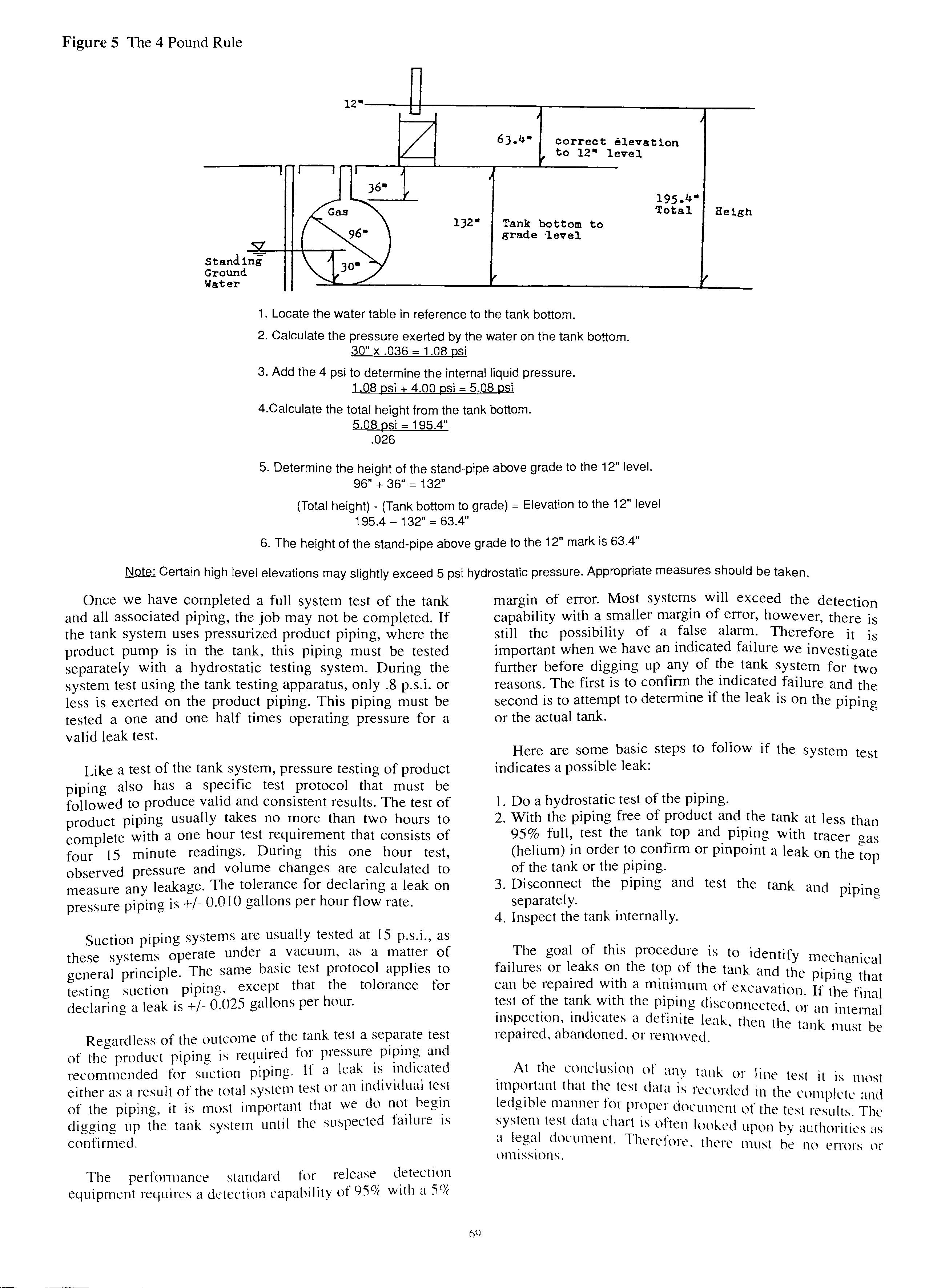
Figure 5 The 4 Pound Rule
SUMMARY
Testing an underground storage tank and the associated pipin g is no easy task. Some people look upon tank testing as more of an art than a sc ience. It is important that testing personnel have a good fundamental understanding of the components of a proper tank installation, a good general understanding of the phys ical properties of a tank system , and that they be trained and certified in the use of the technology required for the test.
Tank testing equipment must meet mm1mum performance requirements and be operated accordincr to a documented test protocol. The must be documented by third party evaluation. And finally, all test data and the results of a tank or line test must be properly documented .
REFERENCES
1. Heath Consultants Inc. , Stoughton, Ma BASIC PRINCIPLES OF TANK TIGHTNESS TESTING.
2. National Fire Protection Association, Quincy, Ma. Publication 329-1987, UNDERGROUND LEAKAGE OF FLAMMABLE AND COMBUSTIBLE LIQUIDS.
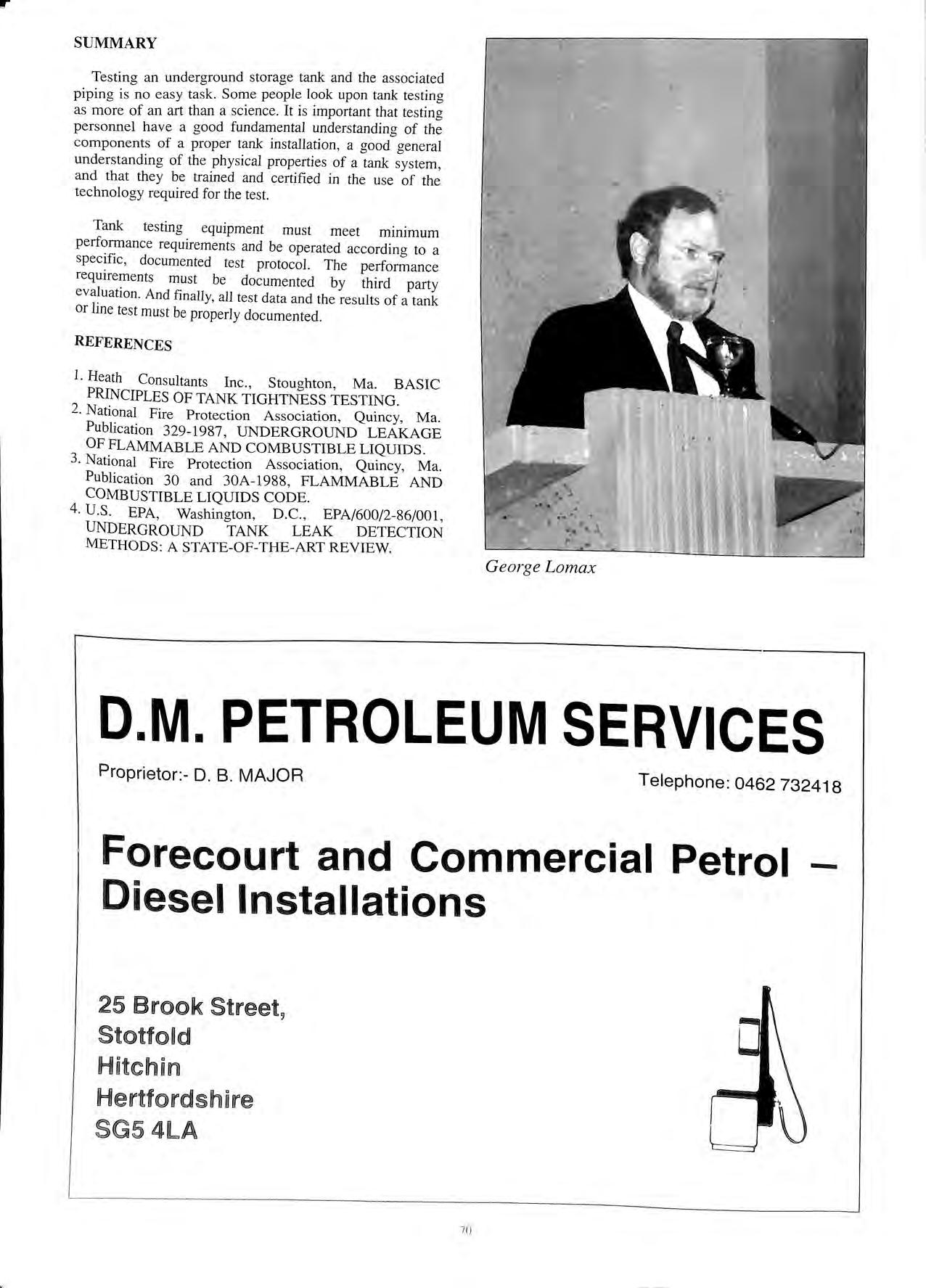
3. National Fire Protection Association , Quincy, Ma. Publication 30 and 30A-198 8, FLAMMABLE AND COMBUSTIBLE LIQUIDS CODE.
4. U.S EPA , Washington, D.C., EPA/600/2-86/001, UNDERGROUND TANK LEAK DETECTION METHODS : A STATE-OF-THE-ART REVIEW.
r
D.M. PETROLEUM SERVICES Proprietor:- D. B. MAJOR Telephone: 0462 732418 Forecourt and Commercial Petrol Diesel Installations 25 Brook Stotfold Hitchirn SG54LA 70 -
George Lomax
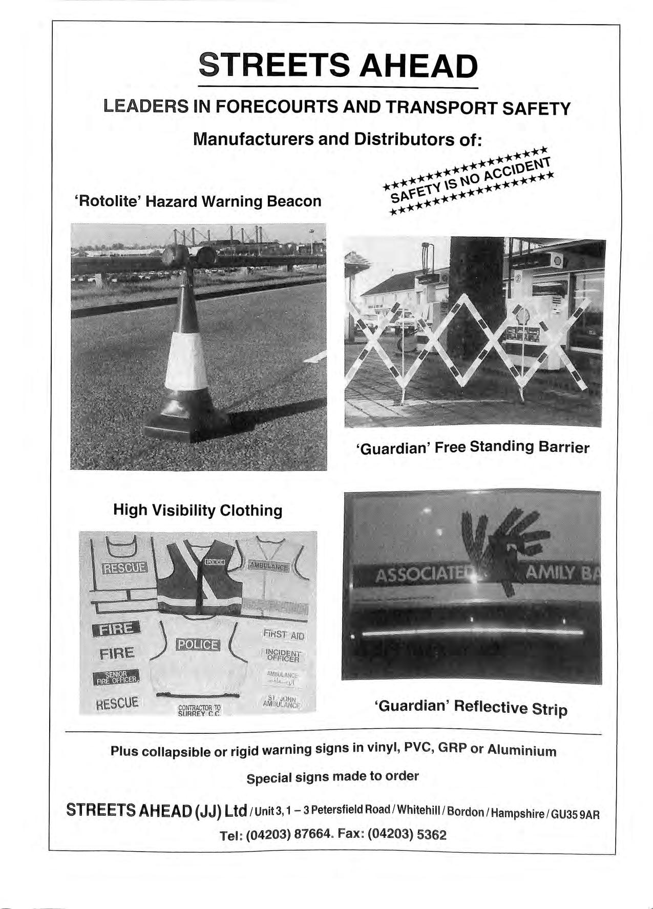
STREETS AHEAD LEADERS IN FORECOURTS AND TRANSPORT SAFETY 'Rotolite' Hazard Warning Beacon High Visibility Clothing ,,, U c ' '111111._.__ . _ _...,_. RE.SC coNTRACmR ro SURREY C C I INCIDENT ' Of'F.ICER 'Guardian' Free Standing Barrier 'Guardian' Reflective Strip Plus collapsible or rigid warning signs in vinyl, PVC, GRP or Aluminium Special signs made to order STREETS AHEAD (JJ) Ltd/ Unit 3, 1 -3 Petersfield Road I Whitehill I Bordon/ Hampshire/ GU35 9AR Tel: (04203) 87664° Fax: (04203) 5362
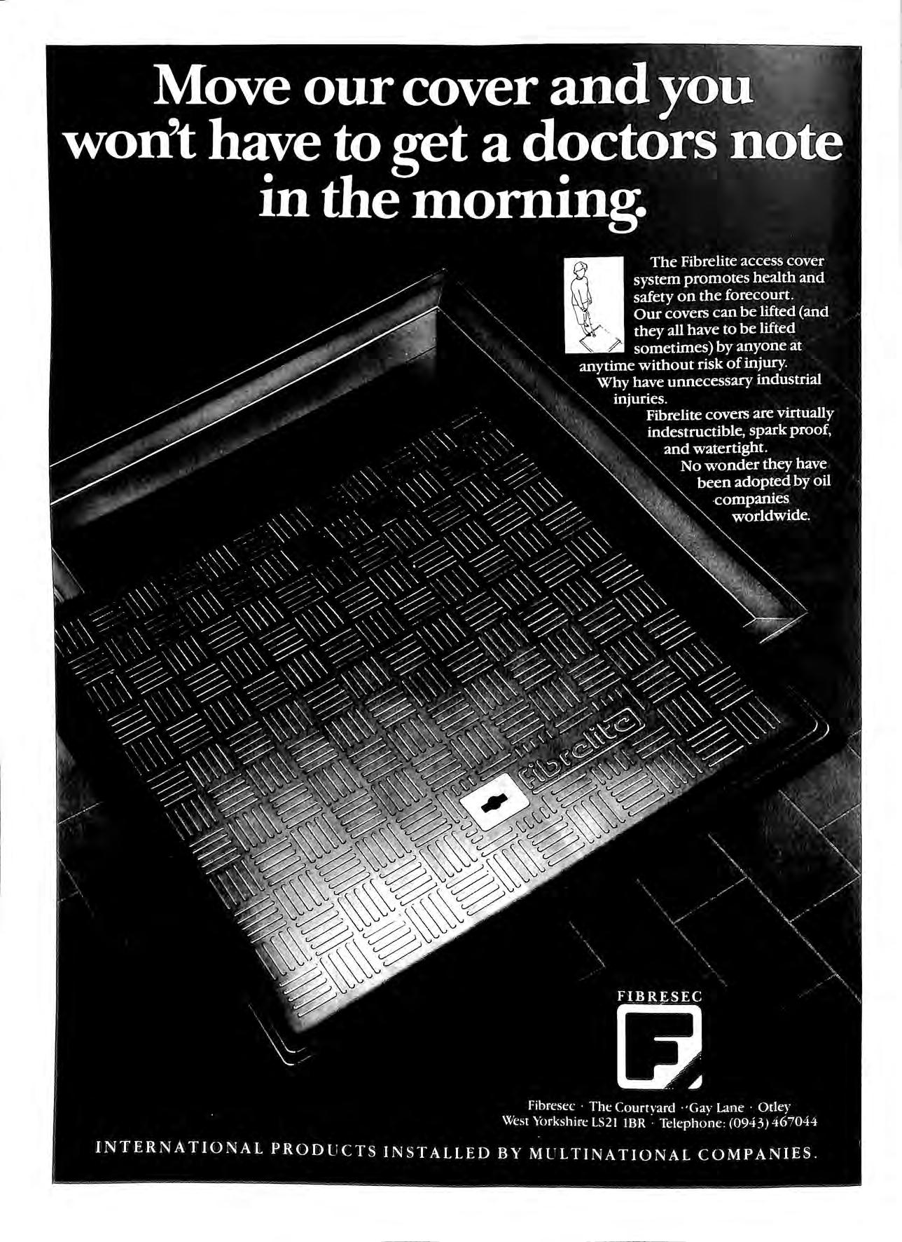
Y OU HAVE COMPLETE CONTROL OF YOUR LIQUID ASSETS?
In today's financial and environmental climate the forecourt operator must have complete control of his wet stock.
No one can afford to allow wet stock losses to go undetected particularly as the new Health and Safety guidelines, HS(G)4 l, require all petroleum retailers to make daily stock reconciliation checks.
Normand has the products that can deliver the control you need to counter any problems you may experience in the area of oil loss. And the ability to offer you practiadvice on the most appropriate package for your service station.
We made our name specialising in supplying the oil industry with
the most successful range of tank gauges in Europe, with complete servicing back-up and calibration expertise.
Together with CMS we helped to develop and perfect Driver Controlled Delivery.
And we're now in the business of protecting you and the environment with a superb range of leak detectors and monitors, as well as consultancy, advisory and risk assessment services from our Environmental Systems division .
We know our range of products will give you both complete performance and peace of mind.
Call us for more information now before you experience any form of stock loss.
Normond Instruments Limited
Hydrex House, Garden Road, Richmond, Surrey TW9 4NR , UK Tel: 081 392 1355 Telex: 9 19193 Fax: 081 878 6642
Nonnoncl
CAPITAL DEMOLITION <NHEJ LTD Specialist removal of fuel tanks General demolition Concrete breaking BYFLEET (09323) 46222 41525 46005 C & S STANSFIELD LIMITED AMERON APPROVED INSTALLER FOR FIBERGLASS PETROLEUM INSTALLATIONS Unit 10 Boundary Road Industrial Estate Sturmer, Haverhill Suffolk, CB9 7YH Tel: 0440 712505 Fax: 0440 712506
OLD
Corroshield have been lining petrol storage tanks for over a decade endorsing our quality of specification and experience in this specialist field
Corroshield System 80 tank rehabilitation is not a repair or temporary solution: (it is new tanks for old) backed by our guarantees extended for as long as you require In any forecourt operation tank
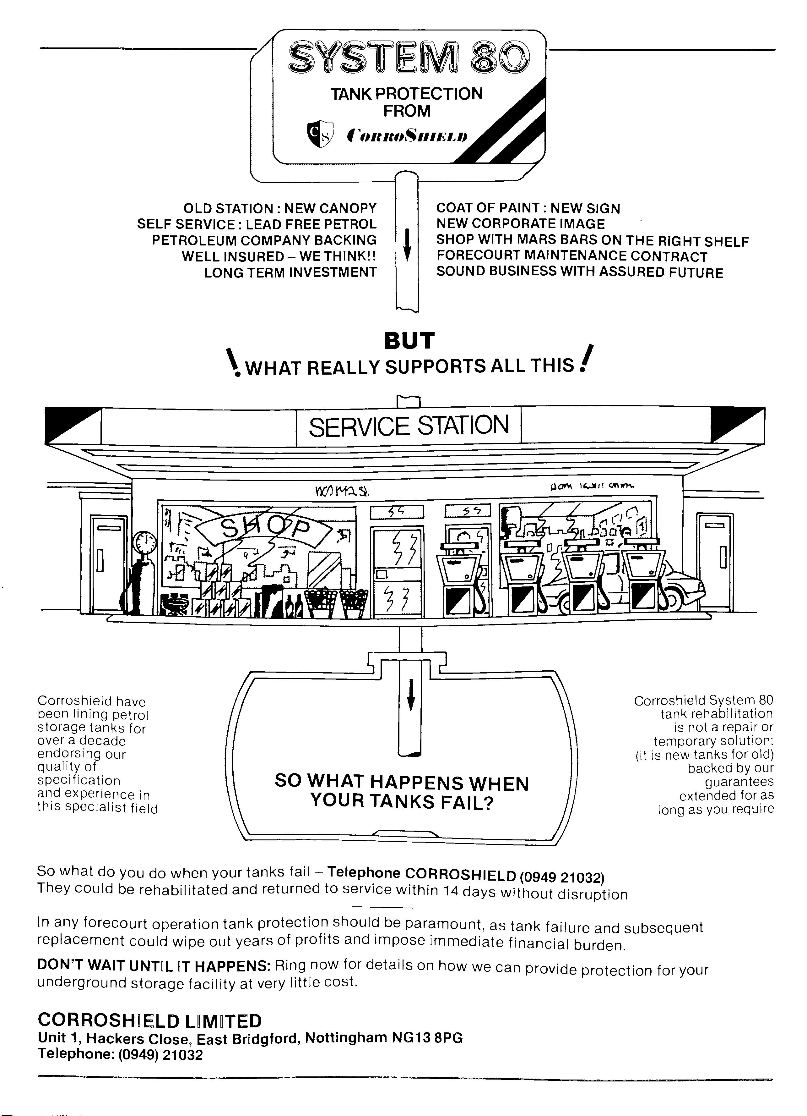
TANK PROTECTION
f
FROM
1(Jlllttl,.,.lllEl,/I
COAT OF PAINT: NEW SIGN NEW CORPORATE IMAGE
STATION: NEW CANOPY SELF SERVICE: LEAD FREE PETROL PETROLEUM COMPANY BACKING WELL INSURED- WE THINK!! LONG TERM INVESTMENT
0
SHOP WITH MARS BARS ON THE RIGHT SHELF FORECOURT MAINTENANCE CONTRACT SOUND BUSINESS WITH ASSURED FUTURE
BUT \WHAT REALL y SUPPORTS ALL THIS I SERVICE STATION SO WHAT HAPPENS WHEN YOUR TANKS FAIL?
you
when your tanks fail - Telephone CORROSHIELD
They
returned
service within
days
So what do
do
(0949 21032)
could be rehabilitated and
to
14
without disruption
be as tank failure and subsequent replacement could wipe out years of profits and impose immediate financial burden.
DON'T WAff n HAPPENS: Ring now for details on how we can provide protection for your underground storage facility at very little cost. Unit 1, Hackers Close, East Bridgford, Nottingham NG13 8PG Telephone: (0949) 21032
COMMERCE HOUSE, THE MALTINGS, STATION ROAD, SAWBRIDGEWORTH, HERTS. CM21 9JX Telephone: 0279 723448
Aden con Draughting Services Ltd.
Specialists in the preparation of drawings for petrol filling service station redevelopments, alterations and tank or equipment installations and obtaining all necessary statutory authority approvals (i.e. planning permission, building regulation approval, petroleum officer approval etc.)
GRAHAM WHITE GARDEN SERVICES Specialists in Forecourt Landscaping, offering National Landscaping Services to all the Oil Companies (Established 10 Years) 32 ONSLOW DRIVE, LEA PARK, TIIAME, OXON OX9 JYY THAME (084 421) 7134
MEMBER A.P.E.A.
PREVENTION DEVICE SAVES THE DAY
At a brand new petrol filling station with overfill prevention devices, one Oil company did not have to wait long before reaping the benefit of installing these devices.
At one delivery the road tanker driver noticed that the tanks could not be filled .as the OPD had operated. The gauge was checked and it was noticed that according to the reading there was still room to install more product.' The hose was drained however and the remaining product was returned to the terminal. The
manager had thought that something had _gone wrong with the overfill prevention device. However, On investigation it was noticed that the numbering of tanks to gauges was incorrect, the gauge that was supposed to refer to the tank in question referred to another tank The fitting of the overfill prevention device saved product loss, possible danger from fire and explosion and of course environmental damage.
The A PEA. Bulletin. August 1990
A wise choice today. For all our tomorrows.
Th e simple fa t is the fo recourt in question was fitted with an OPW 61 SO Overfill Prevention Valve.
Wisely specified by a major multinational it was simple, quick and easy to install (even in existing sites) and soon proved itself in the field.
Needless to say the OPW 61 SO Overfill Prevention Valve is an example of OPW's ongoing commitment to reducing environmental and safety risks on the forecourt, backed up by OPW's leading position in the USA, where the
world's most stringent forecourt safety standards have been in force for some time.
If like the wise multinational, you ' would like to know more about OPW products, contact OPW Fueling Components Europe.
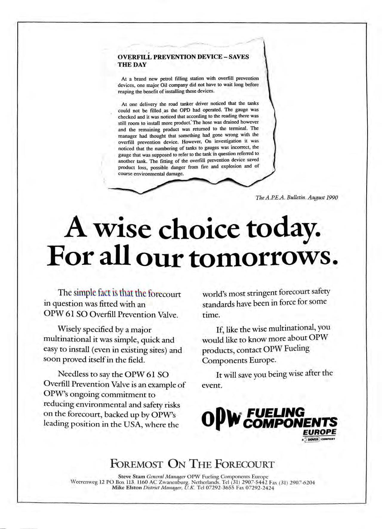
It will save you being wise after the event.
FoREMOST ON THE FORECOURT
Steve Stam General Manager OPW Fueling Components Europe Weerenweg 12 PO Box 113. 1160 AC Zwanenburg. Netherlands. Tel (31 ) 290 7- 5442 Fax ( 31 ) 290 7-62 04 Mike Elston District Manager, UK. T el 07292 3655 Fax 0 729 2-2424
Op lu FUEUNG P COMPONENTS EUROPE
LOXDENE LTD FORECOURT SERVICES Established 1984 CERTIFIED AND EXPERIENCED AMERON GRP INSTALLERS PURPOSE DESIGNED ALL WEATHER INFLATABLE TRENCH COVERS FOR WORKING WITH GRP PIPE CONVENTIONAL STEEL PIPE INSTALLATIONS NATIONWIDE SERVICE APEA MEMBER 45 Vivian Avenue Hendon London, NW4 3XA Tel: 081-202 8035 Fax: 081-202 1642 D DC BUILDERS LTD FOR SERVICE QUALITY & RELIABILITY WE OFFER A COMPLETE SERVICE ON MAINTENANCE AND IMPROVEMENT WORKS TO THE PETROLEUM RETAIL MARKET D D C BUILDERS LTD 7 ST CLAIR CLOSE CLAYHALL, ILFORD ESSEX IGS OPA 081 =550 5216 081 =550 6095
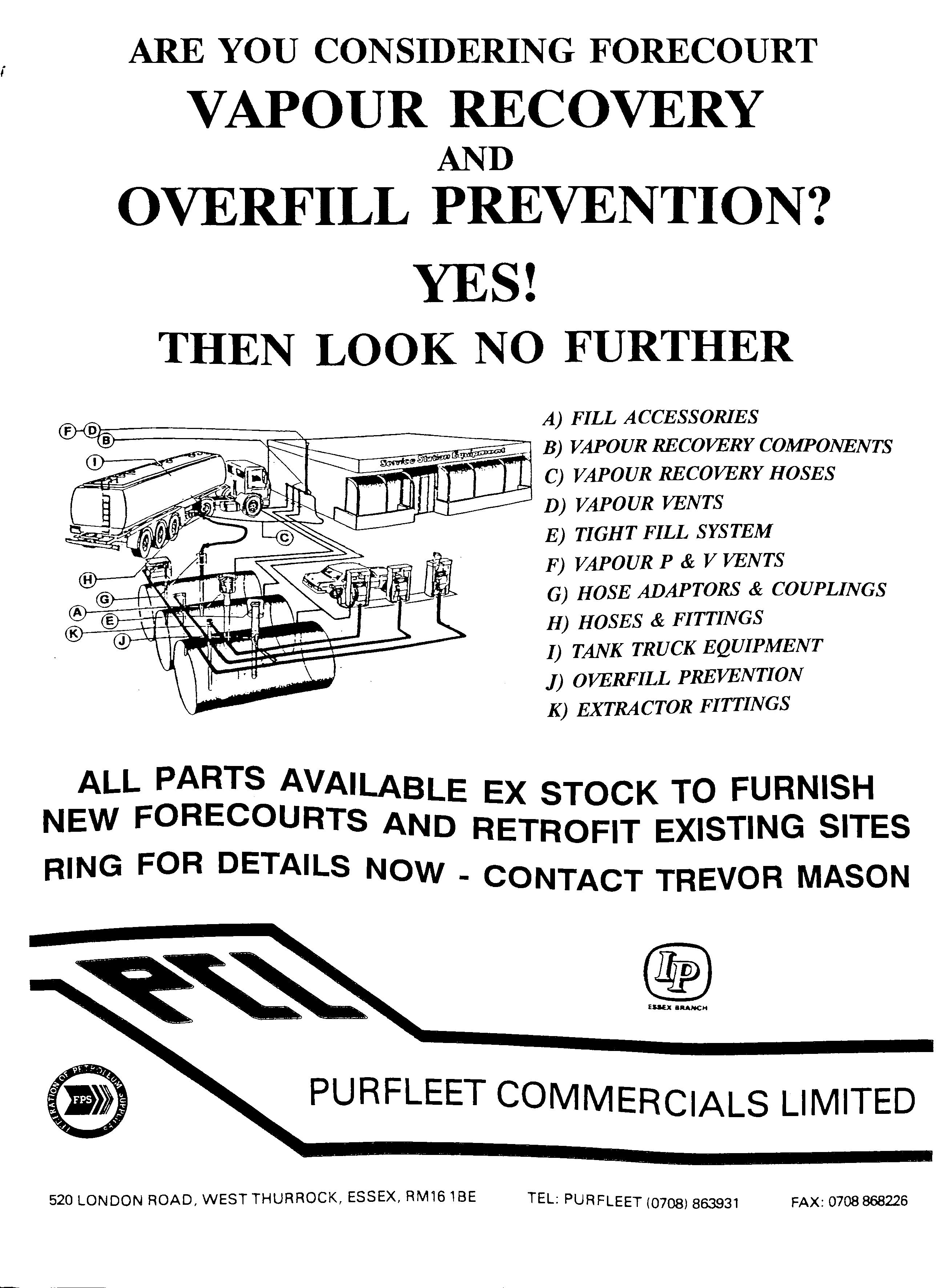
( ARE YOU CONSIDERING FORECOURT VAPOUR RECOVERY AND OVERFILL PREVENTION? YES! THEN LOOK NO FURTHER A) FILL ACCESSORIES B) VAPOUR RECOVERY COMPONENTS --; C) VAPOUR RECOVERY HOSES D) VAPOUR VENTS ----'!---1-'.:2?'".h E) TIGHT FILL SYSTEM F) VAPOUR P & V VENTS G) HOSE ADAPTORS & COUPLINGS H) HOSES & FITTINGS I) TANK TRUCK EQUIPMENT J) OVERFILL PREVENTION K) EXTRACTOR FITTINGS ALL PARTS AVAILABLE EX STOCK TO FURNISH NEW FORECOURTS A,ND RETROFIT EXISTING SITES RING FOR DETAILS NOW - CONTACT TREVOR MASON PURFLEET COMMERCIALS LIMITED 520 LONDON ROAD, WEST THURROCK, ESSEX, AM161BE TEL: PUA FLEET (0708) 863931 FAX: 0708868226
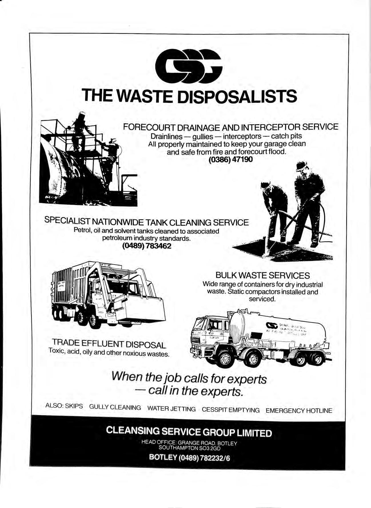
• .., THE WASTE DISPOSALISTS FORECOURT DRAINAGE AND INTERCEPTOR SERVICE Drainlines gullies interceptors - catch pits All properly maintained to keep your garage clean and safe from fire and forecourt flood. (0386) 47190 SPECIALIST NATIONWIDE TANK CLEANING SERVICE Petrol, oil and solvent tanks cleaned to associated petroleum industry standards. (0489) 783462 T RADE EFFLU ENT DISPOSAL Toxic, acid, oily and other noxious wastes. BULK WASTE SERVICES Wide range of containers for dry industrial waste. Static compactors installed and serviced. When the job calls for experts - c all in the experts. ALSO: SKIPS GULLY CLEANING WATER JETTING CESSPIT EMPTYING EMERGENCY HOTLINE
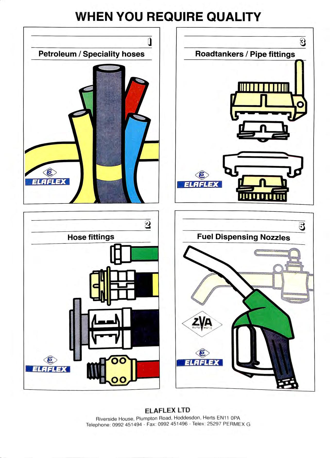
WHEN YOU REQUIRE QUALITY Petroleum I Speciality hoses Roadtankers I Pipe fittings Hose fittings Fuel Dispensing Nozzles ELAFLEX LTD Riverside House , Pl umpton Road , Hoddesdon , Herts EN11 OPA Te lephone : 0992 451494 Fa x: 0992 451496 Tele x 2529 7 PERMEX G
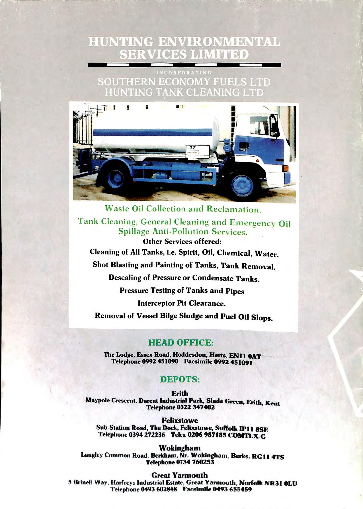
- -Waste Oil Collection and Reclarnalion . Tank Cleaning, General Cleaning and E1nergency Oil Spillage Anti -Pollution Services . Other Services offered: Cleaning of All Tanks, i.e. Spirit, Oil, Chemical, Water. Shot Blasting and Painting of Tanks, Tank Removal. Descaling of Pressure or Condensate Tanks. Pressure Testing of Tanks and Pipes Interceptor Pit Clearance. Removal of Vessel Bilge Sludge and Fuel Oil Slops. HEAD OFFJCE: The l.odge, Hoddesdon, Herts. ENI I OAT · -. ,, Telephone 0992 4.51090 Facsimile 0992 451091 DEPOTS : .Erith Maypole Crescent, ,Darent Industrial .Pal'k•.Slade Green: . Erith" Kent Telephone 0322 347402 · Felixstowe Sub-Station Road, The Dock, Felixstowe, 'Suffolk IPI l 8SE Telephone 0394 272236 Telex 0206 987.185 COMTLX-G Wokingham Langley Common Road, Ber.kham.• Nr. Wokingham. Be:rks. RGI I 4TS Telephone 0734 760253 Great Yarmouth 5 Brinell Way, Harfreys Industrial Estate. G.reat Yannouth. Norfolk NR3 I 0Ll1J Telephone 0493 602848 Facsimlle 0493 655459
