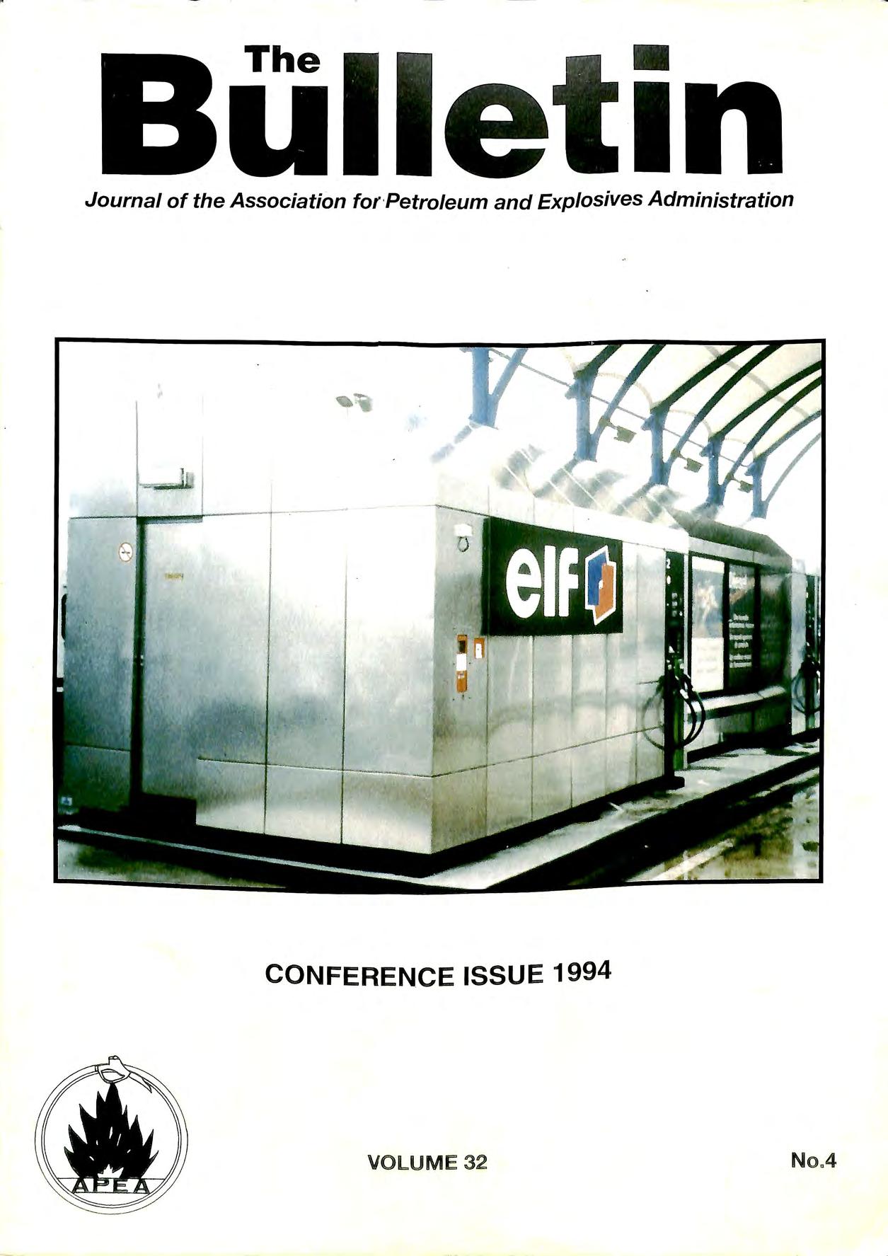
CONFERENCEISSUE1994
The •
Journal of the Association for ·Petroleum and Explosives Administration
VOLUME 32 No A

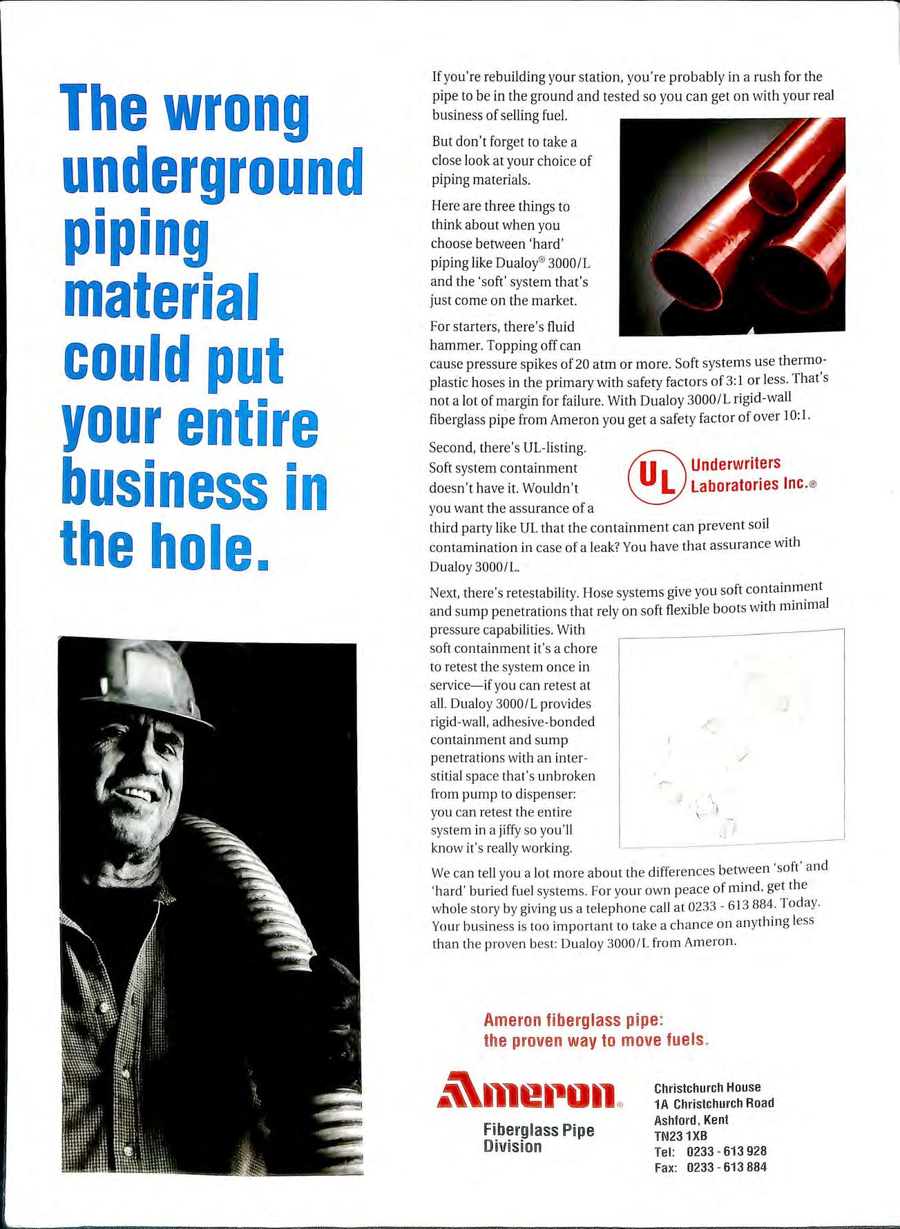
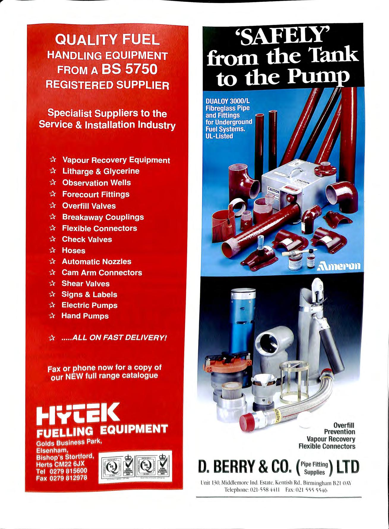
If you're rebuilding your station, you're probably in a rush for the pipe to be in the ground and tested so you can get on with your real business of selling fuel.
But don't forget to take a close look at your choice of piping materials.
Here are three things to think about when you choose between 'hard' piping like Dualoy®3000/L and the 'soft' system that's just come on the market.
For starters, there's fluid hammer. Topping off can cause pressure spikes of 20 atm or more. Soft systems use thermoplastic hoses in the primary with safety factors of 3: 1 or less. That's not a lot of margin for failure. With Dualoy 3000/L rigid-wall fiberglass pipe from Ameron you get a safety factor of over 10: 1.
Second, there's UL-listing. Soft system containment doesn't have it. Wouldn't you want the assurance of a
.@ third party like UL that the containment can prevent soil contamination in case of a leak? You have that assurance with Dualoy 3000/L.
Next, there ' s retestability . Hose systems give you soft containment and sump penetrations that rely on soft flexible boots with minimal pressure capabilities. With soft containment it's a chore to retest the system once in service-if you can retest at all. Dualoy 3000/L provides rigid-wall, adhesive-bonded containment and sump penetrations with an interstitial space that's unbroken from pump to dispenser: you can retest the entire system in a jiffy so you'll know it 's really working.
We can tell you a lot more about the differences between 'soft' and ' hard ' buried fuel system s For your own peace of mind , get the whole story by giving u s a telephone call at 0233 613 884. Toda y Your busin e ss is too imp o rtant to take a ch a nce on anything le ss than the prov e n b es t: Dualoy 3000/L from Ameron.
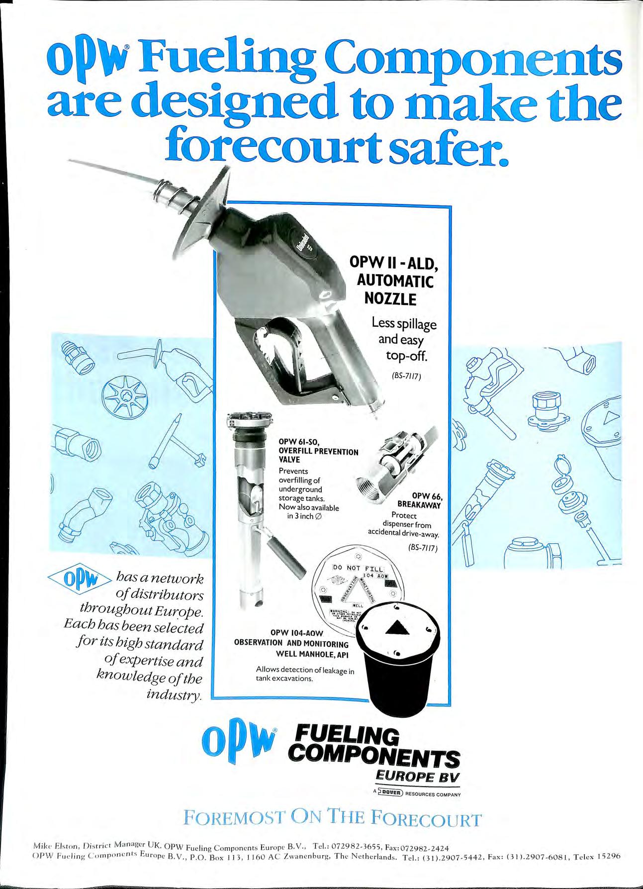
a network distributors throughout Eur_ope. Each has been selected for its high standard ofexpertise and knowledge ofthe industry.

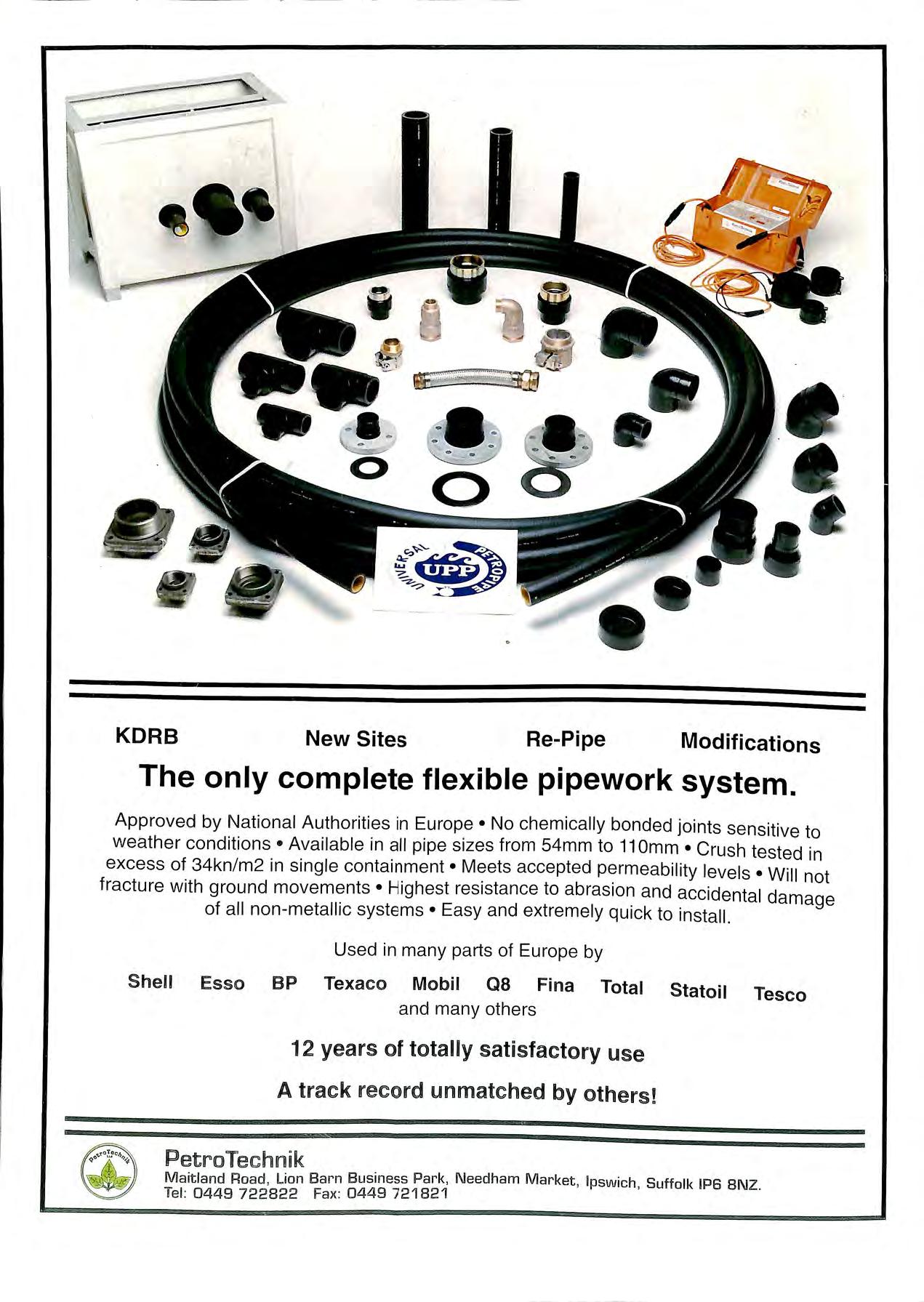
ENVIRQFLEX: For tuel Total secondary c0n1airiment for suctien or pressure systems, or Monofilex for direct burial suction systems. !Easy to inst<il.11 and maintain, comp@l:tible with all fuels and additives currently on the market. lJL. listed.
PElROL-LINE: Fm offset-fill, vent and vapowr recovery. Robust and easy to use, this leak-free petrol anci additive resistant system is bGised cm Durapip@'s patented electrofusion ,jointiri9 method.


This is what 0.1 % fuel loss represents to a typical forecourt operator. Most sites are losing many more times this amount each year!
PetroVend' s SiteSentinel forecourt monitoring system guards against wetstock loss, leaks, theft, short deliveries to mention just a few!

It tells you through accurate printouts and easy to understand graphical analysis, not only how much fuel you are losing on a day by day basis but indicates where in the system the loss is.
It is a modular system that can be
iiJ tailored to your present needs and expanded later.
SiteSentinel is already proving a winner in America because it is easy to understand and use, and pays for itself in real savings .
All members will now be aware that this assoc1at10n providing the facilitator for the technical coordinating for industry to produce the new guidance for petrol filhng station construction, ably aided by the Institute of Petroleui_n who are acting as the secretariat. This work however is being carried out at considerable expense to us the members of this association.
· · · is
The funds could not be met from the annual subscnptIOn b ·1 ver a of £20 per annum. The funds used have been m t up 0 number of years of careful stewardship by officers of association, who have contributed many hours of help and effort into developing the seminars into · 1· ·t d and 1s these funds. The money we have in reserve 1s 1m1 e . small when compared against those held by the beneficiaries of the code of practice the Oil Industry an Hypermarkets. ak
Surely it is time for that section of industry to also m e its contribution.
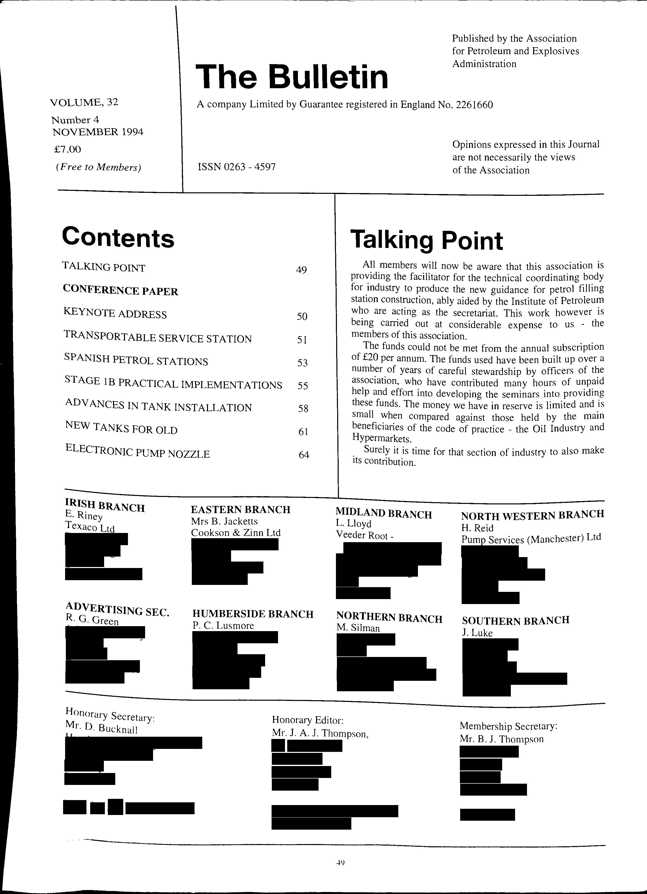
Marketing Director, Elf Oil UK Ltd.
I am very pleased and deeply honoured to have been asked here today, to sunny Binningham , to address this conference. A s you can see the programme covers an important range of issues affecting petrol stations throughout Europe.
All of us here should actively support the A.P.E A. in its to share its considerable expertise more widely in mamland Europe. And I'm sure that this conference will act as a valuable part of that process.
Before we embark on the programme, I would like to touch on three areas which I feel very strongly about because they affect the extent of our future success The subjects are: Common Standards , Research and Training
The harmoni sation of technical standard s is a fi e ld where there is much work to be done.
As .you may know , Elf is one of Europe' s leadina mdu stnal co · d "' ' mp ames a n we are extremely proud to have m being se lected as the so le supplier of petroleum P1?ducts to probably the gre atest civil enaineerina proi ec t in this century th E "' 0 J e u1otunnel , a feat which deserves our pati ence and ultimately our applause wh e n th e fir st c ommercial traffic sta rts in Nov e mber.
Elf has two. station s on the Engli sh sid e and three stations at Calais and 1t would not make se nse if you co Id I h '\ LI ope yo u w1 l '. our servi ce station s at e ither e ncl of th e same tunne l and fmcl th e m des ig ned a nd built to different sta ndard s
I' rn pleased to ass ure you that thi s is not th e case but there many. a reas of di sc repancy e lsew he re in E u rope and I firml y believe th at th e A.P E.A can make a s i£ni fica nt co ntributi o n towards bringing sta nd a rd s into lin e. "'
Petroleum retailing faces a very challenging future not least due to legislative and environmental pressure. On this subject, Elf has an environmental management team which was created over 20 years ago long before green issues became the vogue Why have we been doing this for so long? Because if you take a long term view and we do quite simply the protection of the environment and the efficient use of energy makes sound commercial sense provided that:
• New environmental legislation is supported by sound scientific reasoning rather than emotional lobbying
• change takes due account of the economic costs and the related environmental benefits.
On the more general front, it is clear that the influence of the European Parliament is growing at an increasing rate and here too there will be serious cost implications for our industry.
We at Elf firmly believe that the oil industry has much to gain from collaborating with associations such as the A.P.E.A. to ensure the development of "best practical solutions" to legislative change providing us with technical improvement at minimum cost.
Throughout the day, speakers will dazzle you with innovation, starting -I hope with my colleague from Elf, Malcolm Jones and our mobile service station. In each of today's presentations, whether they concern or finished projects, you will see the benefits of havmg well manaaed research and the desire of our industry to move b forwar·d creatively.
Another area which is vital for all our futures is the provision of the approp1iate training to ensure that our future employees cmTy out their work at as Professionally as they do today. With this m mmd , · ·ai f · the A.P.E.A. offers courses which ar·e essent1 01 ki · d I would mae all of contmmty of aood wor no ptactJce an "' "' "' · h c ·self or for you to find out all about them e1t er i01 yom your employees.
The continued development of the A.P E.A. througfh that 11 ew employees o ow trainmg 1mtiat1ve s can enswe ' f cl industrv won't have to reinvent the principles of sa e ·anal J 11 · I th basis of comme1c1, reliable operations -w JC 1 are e ' success.
I don ' t want to keep you from tod ay ' s presentation s for too long. I will just close by say mg that.
• tl1e development of common standards
• the dev e lopm ent of tomorrow 's tec hnolo gy through re searc h, and f otir workforce for th e futur e
• th e tram mg o
all as whi c h are vit al for o ur success in th e Th ese a1 e ' · rue, l , . they are ar eas whe1e the A.P .E.A . 1c1ve Years to co me, · . . cl I hope yo u w ill talk to th e assoc 1at1on s ex pe rbse an 1 tI l l . t tl ves clurin a th e day to see iow i ey can i e p yo lll re prese n a · o bu sin ess.
1 wish yo u all a very st imula t in g and e nj oyab le conference
T hank yo u ve ry mu c h ladies a nd ge ntl e m e n.
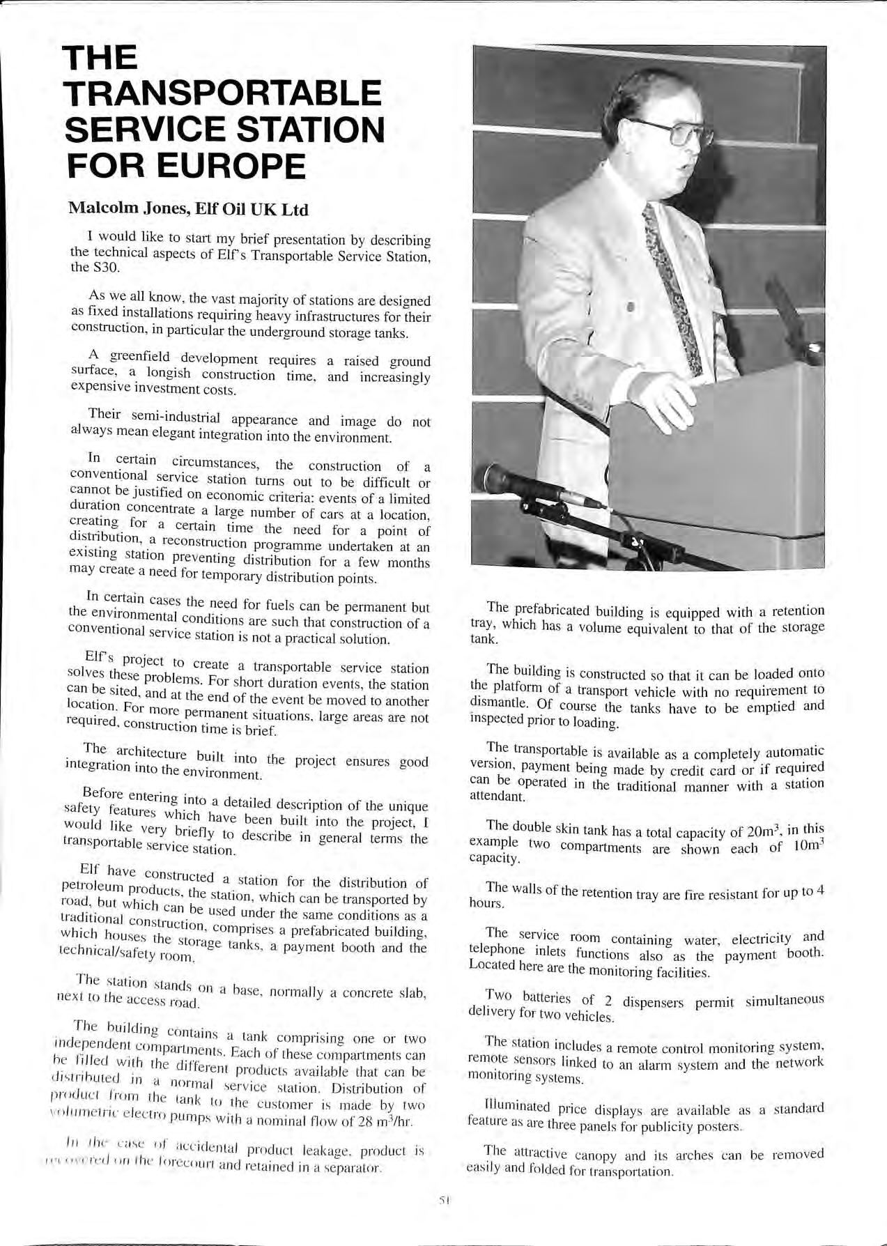
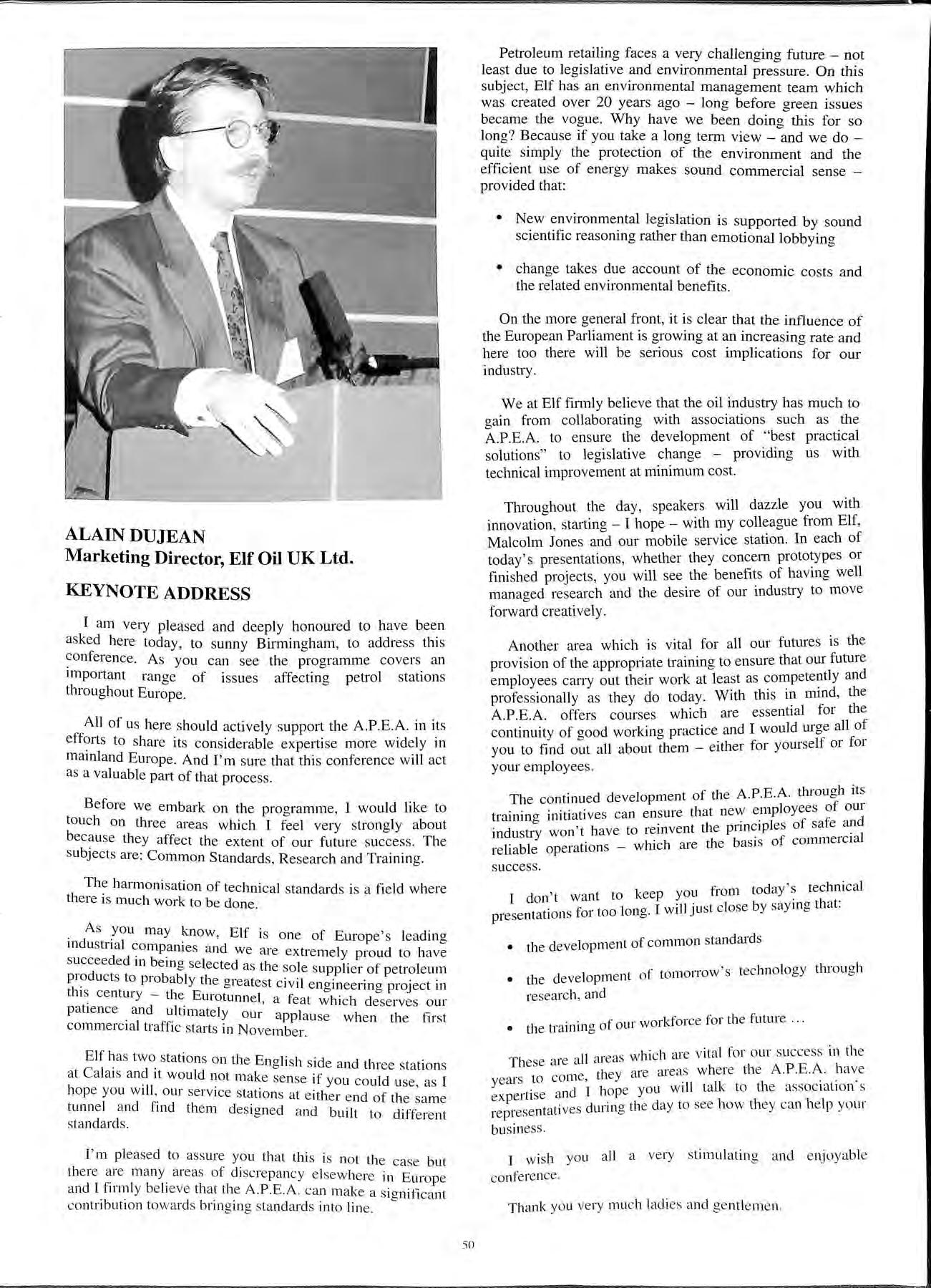
I would like to stait my brief presentation by describing the technical aspects of Elf's Transportable Service Station, the S30.
As we all know, the va st majority of stations are designed as fi x ed installations requiring heavy infrastructures for their construction, in particular the underground storage tanks.
A greenfield development requires a raised ground s urface , a longish con struction time , and increasingly expen sive investment co sts.
Their semi-industiial appearance and image do not always mean elegant integration into the environment.
In ce1tain circum stances , the construction of a conventi onal service station turns out to be difficult or cannot be jus tified on economic criteria : events of a limited duration concentrate a large number of cars at a location , creatm g for a certain time the need for a point of distri_bution , a recon s truction programme undertaken at an ex1st111g station preventing distribution for a few months may create a need for temporary di stribution points
In certain ca ses the need for fuel s ca n be permanent but the environmental conditions are such that construction of a conventional service sta tion is not a practical solution
Elf' s project to cre a te a tran sportable service station s olve s the se problem s. For s hort duration events, the station can be sited , and at the end of the ev e nt be moved to another location For more permanent situation s, large areas are not requtred , con struction time is brief.
The architecture built into the project ensure s good mtegration mto the environment.
Before e ntering into a detailed description of the unique safety fe at11re s which ha ve been built into the project , I would hke very briefly to de scribe in o-eneral term s the tran s portabl e service s tation 0
Elf hav e con s tructed a station for the distribution of products , th e s ta tion , which can be tra nsported by 1 o ad , but whi c h can be used under th e s ame condition s as a c on s tructi o n, co mpri se s a prefabricated building, w ic h the s torage ta nk s, a pa y ment booth and the tec hm ca l/sa fe ty ro om .
Th e s ta ti o n s ta nd s o n a ba se, no rm a ll y a concre te s la b, n ex t to th e access ro ad.
T he b uildin g co ntain s a ta nk co mpri s in g on e o r two rn de p e nd e nt co mpartm e n ts Eac h of th ese co mpartm e nt s ca n h e fill ed w ith th e cliffe re m p ro du c ts a va il a bl e that ca n be d is tribut ed in a n o rmal s e r vice s ta ti o n. Di stributi o n of prod u c t from t he ra n k to th e c us to me r is made by two vo l u m e t r ic e lec t ro p um ps w ith a no min a l fl ow o f 28 m3/ hr
l 11 th e llf acc id e nt a l p rod uc t lea kage , produ ct is 1t'L ' <>vcrcd o n th e fo reco urt a nd reta in ed in a se pa ra to r.
The prefabricated building is equipped with a retention tray, which has a volume equivalent to that of the storage tank
The building is constructed so that it can be loaded onto the pl atfonn of a transport vehicle with no requirement to dismantle. Of course the tanks have to be emptte an cl d inspected prior to loading.
The transportable is available as a completely autom atic vers ion , payment being made by credit card or if can be operated in the traditional manner with a station attendant.
The double skin tank has a total capacity of 20111 3 , in thi ; ex a mple two compartments are shown each of 1Orn capacity.
The walls of the retention tray are fire resistant for up to 4 hours
The service room containing water, el e ctricity and telephone inlets functions al so as the paym e nt booth. Located here are the monitoring facilities.
T b · · · Jtaneou s wo atte ne s of 2 dispen sers permJt s1mu de liv e ry for two vehicle s
The station in clude s a remote control monitoring sy stem , re mote sen sors linked to an alarm s ystem and th e network mo nitoring syste ms
Illuminated pri ce di spla ys are available as a s tandard fea ture as are three pane ls for publi c ity poste rs.
Th e attracti ve ca nopy and its a rc he s can be re mov ed eas il y a nd fold ed fo r tra nspo rtati o n
The material is sublimable, so that in the fire case, instantaneous combustion is achieved without flame or toxic gas.
On moving on to describe in detail, the advanced safety features. I would like to point out that the unit has been designed to satisfy French Authorities.
Clearly the concept of a transportable, completely automated service station, requires a unique approach to safety considerations. The design of the S30 surpasses the standards normally employed in the construction of a traditional station. A detailed risk analysis has been completed for further assurance.
In order to protect against pollution of the surrounding water courses a interceptor can be incorporated into the package.
The area immediately below the forecourt canopy is impermeable, accidental spillage draining directly into the separator.
Elf can provide expertise to advise on the design requirements in order to meet the local guarantees in relation to effluent quality.
The dispensing apparatus, and its ancillary equipment incorporates several unique and innovative features.
Accumulation of vapours within the housing is diminished by the detectors which automatically control a mechanical ventilation.
Non safety related equipment such as indicators, card readers, ticket distributors are housed in a sealed compartment.
The product dispensers are protected against impact by an island wheel bumper.
The dispenser is fitted with an electrovalve to protect against the risk of siphoning.
is automatically terminated after 3 minutes. The delivery hoses themselves are equipped with devices to allow winding and automatic rewinding, therefore after each transaction, the hoses cannot be left lying on the forecourt area.
The nozzle is equipped with an automatic shut off device is when the car is full. A further safety feature is the add1t1on of a device which eliminates flow when the nozzle is in the open air.
The n.ozzle clapper valve is inoperable without manual mtervent10n.
stora.ge tank itself is a double skinned construction with .a leak the pipework is protected agamst mechamcal, physical, chemical or electrolytic action.
hydro.carbon resistant paints are applied to the tank its .ancillary equipment to protect against atmosphenc corrosion.
The tank retention wall is of 5mm sheet steel with a reinforcing ring at the top. This bund is fire resistant for a period up to 4 hours.
The volume of this bund is I 00% of the tank capacity plus the volume of the fire extinguisher products.
Each compartment is fitted with redundant measuring capacity providing stock determination on a continuous basis.
Each compartment is fitted with an offset fill with a movable latch and a permanently attached sealing stopper. A valve and non-return clapper are part of the offset fill product identification and capacity are clearly marked on each fill pipe.
The tank is fitted with a limit switch to prevent overfill, this is complemented by an anti explosion detecting probe, detection by either device automatically closes the valve in the fill line and also stops delivery from the supply pump thereby protecting overfill via the vent line.
Each compartment is fitted with a fixed ventilation pipe. The pipe vents directly to atmosphere via a flame-arresting elbow vent. The vent is visible from the point of fill.
Clearly the installation is equipped with means for fire control that are appropriate to the risks associated with an unmanned fully automatic service station.
Within the tank and its retention wall, an automatic fire extinction system is provided, which includes a foam system, detectors and alarm repeater which is activated following triggering of the automatic system.
The technical control room is protected by smoke detectors and a Halon system, "immediate evacuation" "entry prohibited" alarm panels, a sound alarm and a break glass alarm are standard features.
A 1OOkg powder extinguisher is also sited in the control room for back-up facilities.
A remote manual control, outside of the distribution can activate the automatic devices.
The method and materials of constrnction of the tank enclosure have been designed to maintain a fire barrier for 2 hours, the structure supporting the assembly and the retention tank give fire resistance for 4 hours.
A gas detector is situated above the tank, following activation, an extractor fan operates at a flow rate of 1080 m3/h.
The extraction orifices are protected by fusible links that close in the event of temperature increase.
The technical room which is in contact with . a remote depot is itself fitted with a 2 hour fire door to the outside and is fitted with an openmg ?ar. The room is naturally ventilated at both high and low pomts. . . f the alarms the detection system and the t matic and the general cutoperat10n 0 t e au 0 l" 'tl b ak ·e retransmitted by modem to an exp 1c1 y out re, e1 ai ' · designated competent person. h 1 t · al equipment and the ultrasound gauging All t e e ec nc are safety approved equipment .wh1ch1 c.onfonn to1 "Electrical equipment items usable 111 exp os1ve atmosp 1ere European standards.
That concludes my presentation on the S30.
Two models of which are in operation in France at Nantes and at Magny Cours.

Spain is the second largest country in Western Europe in size (after France) and the 5th in population (after Germany, Italy , France and the U.K.) and its GNP is the l lth of the world
If we, now , look the rates in the fuel retail business , such as the total number of service stations (5,500) per sq km , the number of cars per 1,000 inhabitants (almost 100 less than the average in western Europe), the annual growth in con s umption (almost the double than the average in western Europe, again), we will realize about the potential growth of this market in the next years.
Passing from 4,900 service station s in 1989 to an estimation (maturity year) of 7,600 in the year 2,000 means actually:
MORE THAN 250 uPGRADED SERVICE STATIONS PER YEAR
MORE THAN 700 MAJOR SERVICE STATION CONSTRUCTION WORKS PER YEAR
MORE THAN 15 MAJOR PETROL COMPANIES " FIGHTING " FOR THE MARKET and I say " fi g hting " because if we have a look to:
a) Minimum distance requireme nt s
b) The permit procedure that obliges everybody that wishes to build a se rvice sta tion in a certain area are affected by the. time to co ll ect all the different pernut s throughout a penod of time that var ies from 6 months to more than o ne year (MUNICTPALITY ROAD AGENCY, ENVIRON ME NTAL AGENCY , AND OTHER MINOR ?NES J with the final obj ect i ve of the application form for th e PROVIS IO NAL IN SC RIPTION (la s t permit that a ll ows yo u to bui ld and ope rate the se r vice s tation) that w i 11 o n ly be iss ued to th e FJRST o ne that ha s all the prev io us pe rmit s co rrec t.
T hai that the re s t a imin g for th e ir pe rmit in th e a re a ha ve a ll be e n was ting th e ir tim e and mon ey
REPSOL (59% in total sales and 65% in Retai outlets)
OWNED 51% BY THE STATE
5 REFINERIES IN THE MAINLAND OF SPAIN 4TH PETROL COMPANY IN EUROPE FUEL RETAIL BUSINESS OPERATIONS IN PORTUGAL, FRANCE AND THE U.K
CEPSA/ELF (25% in total sales) APPROX 30% OWNED BY ELF THE OTHER MAJOR SHAREHOLDER IS ONE OF THE SPANISH MAJOR BANKS
3 REFINERIES (ONE IN THE CANARY ISLANDS)
BP Oil (Almost a 8% in total sales) TOOK OVER 100% OF PETROMED IN 1990 I REFINERY IN THE MEDITERRANEAN COAST
THE REST (9% in total sales)
SHELL
PETROGAL
TOTAL AGIP MOBIL TAMOIL ESSO SA ROIL
Q8 PETROFINA TEXACO
ELF AVANT! M EROIL OILDOR
There are maj or difference s in the ex pa ns ion plan s of the co mpanie s becau se meanwhile so me o · ' . 0 1 f them are trym a to ach ie ve a na tiona l c hain, othe rs are co nce ntrated Ill on Y ce rtain reg ion s
But what is the current situation making business in the spanish market attending all the above?
Our company Mobil Oil decided on a strategy of approach to the authorities to help them with the aim of changing the "status quo". If we think the local authorities of the Energy Dpts. are suffering the situation even more than us, you will understand that they are keen to change and are open to any kind of technical discussion and proposal.
These are much more difficult if you are facing the seventeen different regions and authorities because that will always remain the differences m approach and understanding.
Mobil Oil in the regions we are dealing with have obtained the first approvals (general approval) for GRP tanks and we have also obtained the approval for a pilot site (a real NTI) with pressure system and flexible inert pipe (the first one in Spain) that was completed in April of this year and a previous GRP pipe installation with suction systems completed in December 1993 (the first non-steel installation in Spain). With the above we have demonstrated that instead of claiming against the administrators for not changing the rules of the game (which is the approach of other petrol companies) our method is demonstrably much more successful.
That approach of Mobil has been always of a joint operation with the interested suppliers with a common aim, objective and goals: the approvals of certain equipments, materials and systems that are Mobil engineering standards and policies and, on the other hand, business for suppliers.
Let us have a look now at the current status in Spain.
Pressure is not allowed.
Individual suction lines from individual tanks (compartments and syphons are now allowed) has made the first pilot sites for pressure mstallations in Spain, currently being monitored by authorities, other companies have now under construction other pilot sites in other parts of Spain.
steel (single or double) or GRP (only in several regions) tank conc.rete pit compulsory (future legislation will obly that only m presence of water or in urban areas
Now
The expected new national frame legislation includes a test yearly after I 0 or 12 years according to the s1tuat1on and scenaiios
Looking to the .bar diagram you will realize that the average m Spain is nowadays the double than the average m western european countries.
couldb thinfk that rate will change when the matunty num er o service. will be achieved (ai·ound 50% more than now), but 1f we make a simple aryth .· 1 · h' k' · met1ca exercise t m mg 111 an annual growth of 4% and the growthness the c_ar density to reach average european we will obtam more than 2.? million litres per year per site (25% more than the average 111 west Europe).
Spain is administratively divided in 17 Autonomic Regions with their own Governments and Parliaments and capability to legislate in different matters, although not all the regions has the same empowerment (competences transferred from the Central Government) to do so.
The current scenario is based in the following principles:
1. National legislation frame from 1936
There is a new law pending to be published since 1989, the last released in 1994 is now in Brussels (last stage) and is expected to be finally approved and published until this year end.
Each region has the capability of approved materials, equipments and systems but the lack of a national frame put them in a difficult situation, therefore obly the actors of the market to 'maintain a single approach region by region to obtain approvals of the immensity of materials, equipments and systems that obviously do not appear in the 1936 current legislation.
3. The law of "liberalization of the industry" that pass through the responsibility from the officials/administrators to the following actors:
a) Chartered engineers that design and supervise the construction and installation works
b) Registered Installers (electricians, pipe fitters, water pipe fitters, etc.) with an official card that allows them to be contracted by contractors and particulars
c) Regulatory Inspection and Control Bodies that, on behalf of the Administration and Consumers, looks after the "fair play" and the compliance with laws and other regulements.
Voluntary
SPILL CONTAINERS, SITE SURVEYS, MONITORY Marketing/Competition driven (the majority of the companies are installing everything nowadays) PUMPS/SUB PUMPS Type homologation
Steel or galvanized steel Mobil has two sites under evaluation by_ 'th GRP pipes and the other with an 111e1 t one w1 _ . S . ) flexible double skin system. (the first m pam
W · · EEC Jecrislation to be approved and the at tmg e · 1 I · I · D · t be 1 ·ncorporated to the nat1ona eg1s at1on. trect1ve o TI · r cotnpanies are installing the vapour ready 1e maJO · t'ncr t'nstallation in all the sites. pip e ·
Municipality regulations (no national rules or legislation)
That is all, ladies and gentlemen, from the typical topics of Spain such as the sun, the P_aella, the sheny wine, the flamingo let me, perhaps, mclude the service station business nowadays!!!
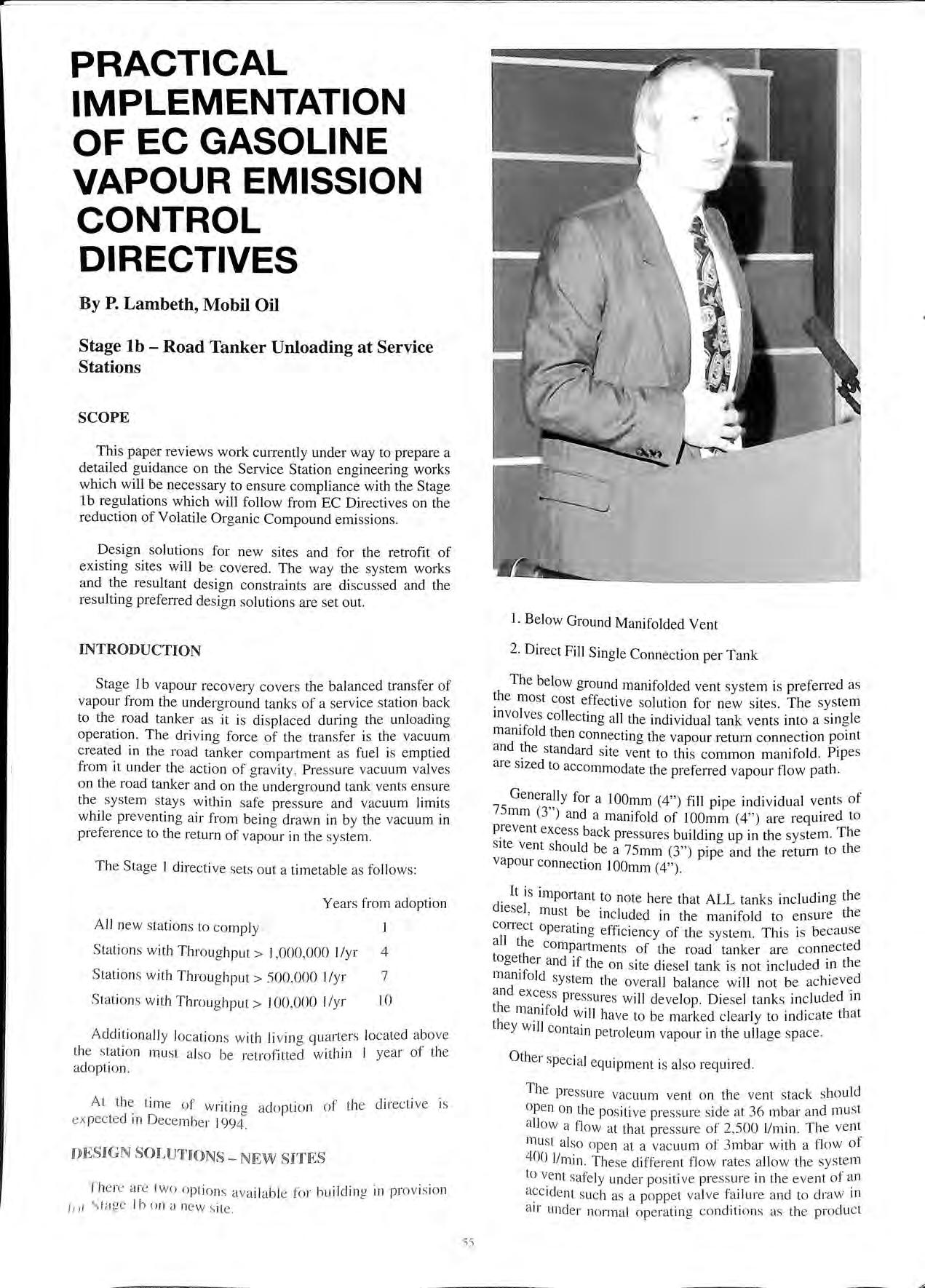 By P. Lambeth, Mobil Oil
This paper reviews work currently under way to prepare a detailed guidance on the Service Station engineering works which will be necessary to ensure compliance with the Stage 1b regulations which will follow from EC Directives on the reduction of Volatile Organic Compound emissions.
Design solutions for new sites and for the retrofit of existing sites will be covered. The way the system works and the resultant design constraints are discus se d and the resulting preferred design solutions are set out.
Stage lb vapour recovery covers the balanced transfer of vapour from the underground tank s of a service station back to the road ta nker as it is di splaced during the unloading operation. The driving force of the tra nsfer is the vac uum created in the road tanker compartment as fuel is emptied from it under the action of gravity. Pre ss ure vacuum valves on the road tanker and on the underground tank ve nt s ensure the syste m stays within safe pre ss ure and vacuum limits while preventing air from being drawn in by the vacuum in preference to the return of vapour in the sys tem.
The Stage I directiv e sets out a timetable as follows:
The below ground manifolded vent system is preferred as most cost effective solution for new sites. The system mvo!ves collecting all the individual tank vents into a single marnfold then connecting the vapour return connection point and the standard site vent to this common manifold. Pipes are sized to accommodate the preferred vapour flow path .
for a lOOmm (4") fill pipe individual vents of 75 mm (3 ) and a manifold of I OOmm (4 ") are required to P.revent exces s back pressures buildina up in the system. The site vent should be a 75mm (3") and the return to the vapour connection JOOmm (4").
All new s tation s to co mpl y
Sta ti o ns w ith Throughput> l ,000,000 1/yr 4
Stat io ns wit h T hrou gh put > 500 ,000 1/yr 7
Sta tion s with Throug hput > I 00,000 I/yr 10
Add iti ona ll y locat ions with Ji vin g quarter s lo c ated above the stati o n mu st a lso be re trofitte d w ithin I year of the adoption.
At the time of w ritin g ado pti on of the d irec ti ve is ex pec te d 1n Decembe r l 994.
T he re are two opt ion s a va il ab le for bu il ding in provi s ion /n l ") !a ge I bona ne w s ite.
I . t is important to note here that ALL tanks including the diesel , mu st be included in the manifold to ensure the correct operating efficiency of the system. This is becau se all the compartments of the road tanker are connected together and if the on s ite diesel tank is not included in the marnfold syste m the overall balance will not be achieved a nd exces s pressure s will develop. Die se l tank s included in the manifold will have to be marked clearly to indicate that th ey will contain petroleum vapour in the ullage space.
The pressure vacuum vent on the ve nt stack should open on the positive pre ss ure s ide a t 36 mbar a nd mu st a ll ow a flow at that pre ss ure of 2,500 l/min. The vent mu st a lso ope n at a vacuum of 3mbar with a flow of 400 l/min. T hese different flow rates a ll ow th e sys tem to ve nt safely und er po s itive press ure in the event of a.n acc id e nt such as a poppet va lve fa ilure and to draw in air und e r normal operating conditi o ns as t he produ ct
level in the tank is drawn down. At the same time it prevents a large volume of air from being drawn in during high vacuum conditions in the first few seconds of the unloading process which would decrease the efficiency of the balanced system.
At the fill points a valve will be required on the fill cap to allow the safe removal of the cap while the top of the fill pipe is under a small excess pressure. This pressure is derived from a balancing between the tanks, through the vent manifold, of pressures developed during unloading or, in the future, with Stage 2 Vapour recovery systems.
The road tanker connection point on the site is fitted at the end of the lOOmm return line. It should be a lOOmm or 75mm high flow fitting complete with a built in flame arrester. The fitting should be clearly marked and sufficiently different from fuel fill pipe fittings to avoid the inadvertent connection of a fuel hose.
With a below ground manifold it is wise to provide protection against crossover in the event of an overfill. This can be provided either by means of a reliable overfill prevention system or by providing a ball float valve on the vent at the tank lid.
A single connection per tank may be utilised in the case of small tank farms or of isolated tanks. This can take the form of either a coaxial adaptor or of separate fill and recovery connections at the same tank lid. Tankers are only equipped with a single hose and a single vapour connection point. If it is wished to drop more than a single compartment at a time then a & connector and an additional hose will have to be retained on the site.
In considering existing sites they will be split into three standard types related to the type of fills, direct or offset, and the relationship of the fills and the vents. The vast majority of sites will fit into one of these categories.
Type 1.
2.
Two options are available for the retrofit of sites where the vent stack is located adjacent to the offset fills:
The above ground manifold is a very simple and economical way of collecting all the vent lines together into o?e common line in order to allow the return of the displaced vapour back to the road tanker. With fill points close to the vents only a very short length f t · ·11 b · o re um pipe w1 e required. In some cases _the vapour connection point may b_e built as pait of the ma111fold. The existing vent iisers are cut off and capped with Tees which can then be JOmed to form the manifold. As with the below ground ma111fold some form of c1·oss co t · t' n amma 10n protect10n needs to be A single vent riser can then be attached to the ma111fold to provide the normal r 0 function. ven me
On sites where the fills .and vents are a long way from the tank a below ground mamfold may prove necessary to oive a suitably efficient Stage 1 system. e
Again two alternative options are available:
I. Below Ground Manifold
2.
In this instance the most suitable solution will be the provision of a new below ground manifold. This will ensure that pressure loss in the vent return system is minimised.
The alternative solution will only be suitable in cases where the length of the vapour return line is such that the pressure loss in the line between the above ground manifold and the tanker compartment is less than that from the manifold to the top of the vent stack which will always be simply the length of the vent stack. A lOOmrn (4") return line will almost always be necessary in this type of case.
Three options are available for direct fill sites:
1. Below Ground Manifold
2. Above Ground Manifold and Return
3.
The most effective solution for direct fill sites is most likely to be the below ground manifold. Such a manifold could be connected through the tank lid chambers for adjacent tanks in order to minimise forecourt excavation. Existing vents could also be retained in this case.
The installation of an above ground Manifold will also be an option where the tank vents are not too distant from the fill area.
For small sites or sites with isolated tanks the most economical solution may involve the use of a c? adaptor. The operational restrictions associated with this method will also have to be taken into account.
The simple aim of the design of the Stage I vapour recovery system is to make the preferential vapour flow path that between the storage tank and road factors have an influence on how effectively that aim can b achieved. The most important of these ai·e:
Fill flow rate : Fill pipe size and length
No. of consecutive fills
Vapour flow rate: vent pipe size and length, bends and fittings
dd .t. factors which affect the ainount ?f vapour In a 1 ion ff.. · h h a 1 be . d l have an effect on the e 1c1ency w ic c I generate a so achieved by the finished system. Such factors aie.
Fuel temperature in tanker and tank
Atmospheric pressure
Tank ullage
Vapour density
The desion guidance to be prepared will be in the form of a flow or nomograph will enable designers to determine the optimum solution for the particular pipe lengths and sizes. they hav.e on sties. Different charts will be prepared tor the v•mous site types.

The main parameters within which the design must work are dictated by the pressure vacuum valve setting on the vent stack. These are at:
+ 36 mbar at 2,500 1/min and 3 mbar at 400 1/min.
Increasingly these pressures would increase the efficiency of the system and allow the use of smaller sized pipes in the vent and manifold system.
A positive pressure of 36mbar, however, will push a column of fuel up approx 0.5m. Increasing the pressure in the system before venting takes place creates the risk of pushing fuel out of low direct fill pipes and low lying petrol pumps.
Additionally on the vacuum side a light vacuum is essential to allow the correct functioning of suction pumps.
For these reasons changes in the p-v valve settings are not included in the standard solutions to be proposed.
Table 1 shows the head loss in mbars for a 30m length of Various sizes of pipe under a number of different flow rate conditions
Pipe Size
Flow Rate 38mm 50mm 75mm lOOmm
600 Umin 32 8.4 1.2 0.3
1200 Umin 103 26 3.8 1.0
2200 Umin 298 80 11 2.8
Table 1.
The flow rates of 600 l/min, 1200 l/min and 2200 l/min are equivalent to a single 75mm drop, a single lOOmm drop and a double lOOmm drop respectively. The head loss is calculated on the basis of an incompressible flow. Petrol vap · our is not incompressible however the figures shown do give .a good indication of the scale of the pressure loss when relative to pipe size and flow rate.
Table 2 gives similar head loss figures for a typical vent system.
Pipe Size
Flow Rate 38mm 50mm 75mm IOOmm
600 l/min 60 24 9 5 1200 l/min 180 60 14 8 2200 l/min >300 155 30 12
Table 2.
The one lesson which can clearly be taken from this initial work is that the conventional use of 50mm pipes for 1 ·111-.. will present a number of problems in minimising the , ',,11 111 head losses especially on sites with long vent runs. I I11 ;n °mmended sizes for use in the underground vent ,, 1;JJ 11 Iuld '-Ystem are 7'irnm spurs to a IOOmm manifold.

Field trials will be carried out to verify the accuracy of the calculation process before the proposed guidance is finalised. A number of tests have already been carried out and the results from one of these is shown on the attached graph.
The graph shows that on the site tested where the vent runs were less than Sm to an above ground manifold the system worked well and efficiently. A total back pressure of 14 mbar was recorded between the underground tank and the tanker compartment. Pressure losses on the site accounted for 6 mbar of this total with the remaining 8mbar in the connection, hose, couplings and internal pipework of the tanker. An important lesson from this trial was that the pressure losses in the tanker and necessary fixed equipment clearly absorbed a significant portion of the available pressure driving force of 36 mbar at the vent stack.
The aim of the Stage 1 design process is to ensure that the preferential vapour flow path is that between the underground storage tank and the road tanker. The design must ensure that pressures in the system do not get to levels where pressure-vacuum valves would be opened allowing air to be drawn in to the system or vapour to be vented.
For new sites the recommended design solution is the installation of a new below ground manifolded vent system.
For existing sites above ground manifolds and new below ground manifolds will generally offer the most cost effective solution depending on the site layout. For some smaller sites the option of a coaxial adaptor will be most suitable.
A. guidance document, now in preparation, will published by The Institute of Petroleum next year. This document will allow you to derive the optimum design s?lution of system type and pipe sizing for any particular Site.
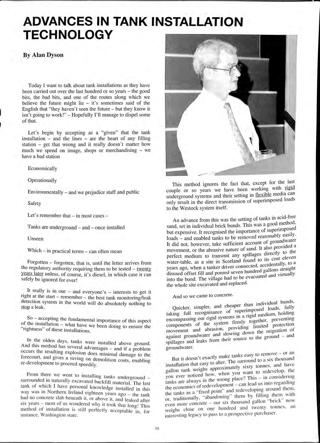
Today I want to talk about tank installations as they have been carried out over the last hundred or so years the good bits , the bad bits, and one of the routes along which we believe the future might lie it ' s sometimes said of the English that "they h a ven't seen the future but they know it isn't going to work!" Hopefully I'll manage to dispel some of that.
Let's begin by accepting as a "given" that the tank installation and the lines are the heart of any filling station get that wrong and it really doesn't matter how much we spend on image, shops or merchandising we have a bad station
Environmentally and we prejudice staff and public Safety
Let ' s remember that in most cases
Tanks are underground and once installed
Unseen
Which in practical terms can often mean
Forgotten forgotten, that is, until the letter an-ives from the regulatory authority requi1ing them to be tested twenty years later unless , of course, it ' s diesel, in which case it c a n safely be ignored for ever!
It really is in our and everyone's interests to get it nght the start remember the best tank monitoring/leak detect10n system in the world will do absolutely nothing to stop a leak
So acceptin a the fund 1 · . f h <=> amenta importance of this aspect o t e 111stallat10n what h b . " rightnes s" f th . we een domg to e nsure the o e se 111 stallat10n s .
In the olden days tank And this method h ' . s were 111stalled above ground. . . as seveial advantag es -a nd if a roblem occm s the re s ultma explo s ion do 1 P f 0 e s mrn1ma dam a ae to th e 01ecomt , a nd g ive s a sa vina o n d r 0 re-dev e lopme nt top d 0 e m o it.ion cos ts, e nabling 10cee sp eed J] y
From there we we nt to in t lli s a ng ta nk s und e raround S UII ound ecl m naturally ex c avat ed backf·11 · 0 f · ' 1 m a ten al. Th e las t tank o ""'.hi c h I h av e pe rso nal kn ow led ge in stalle d in thi s wa y w as 111 No rthe rn Ireland e io- htee n ye ai·s a 1 • • <=> ' 'go t 1e ta nk had no con c re te s la b be ne ath 1t o r a bo ve it ai1d l ak cl f , , e, e a ter si x years n1os t of us wo nd e re d w hy it to o k th at l o- I TI · l d 1 fi · · On 0 ll S me t 10 o · 111 sta a t1 o n I S st1 It pe r fec tl y acce pt a bl · fo;· in sta nce, Was hin g to n s ta te. e 111 '
This method ignores the fact that, except for. the _la_st couple or so years we have been working with ngid undero-round systems and their setting in flexible media can only in the direct transmission of superimposed loads to the Westock system itself.
An advance from this was the setting of tanks in acid-free sand, set in individual brick bunds. This was a good methodd but expensive. It recognised the importance of loads and enabled tanks to be removed reasonably easily. It did not however take sufficient account of or the abrasive nature of sand. It al s o provide ha ' . d tl to t e perfect medium to transmit any spillages J[eC Y 1 cl f d to its cost e even water-table as a site in Scotlan oun ll t a ' · t d accidenta Y' 0 years ago when a tanker clnver connec e ' · ht ' h dred gallon s straJg disused offset fill and poured seven un and viJtually into the bund. The village had to be e vacu ated the whole site excavated and replaced
And so we came to concrete.
tllan individu al bunds , Quicker, simpler: and cheape1 · o sed loads , fully taking full recogrusance of medium holding ·d t s111a1io-i ' encompassmg our ngi sys em _ 1' t 0 a-e th e r prev e nting f tl stem fm1uy Oa ' · components o 1e ·ovidina limited protec t10n movemen t and abra sIOn , pi. d 0 th e mi o- ration of d . d slowm a own <=> against groun water an <=> • t th e a-round and ·11 d leaks from tll eir somce o o sp1 age s an groundwater.
.
, make tank s easy to re m o ve o r a n
But d oes n t exac tl y It Th e s urro und to a s ix thou sand in s tallati o n th at eas y to a eL 1 ·xty tonn es a nd h a v e g allon tank to th e You ev e r noti ced ho w , w e n Y · · 1 .· o- th e w ron o- pl ace? Thi s Ill co ns ic e t tn o tank s are alw ays rn ° · . o- d· 0 . . of i·ecl eve lo pme nt can lead us int o i eoai m "' th e eco no1111 cs . . d l k " f'"xed poin t" and re d eve lo prn g a10 un t 1e m. th e ta n ' S as a 1 · · h d·r· Jl y "a ba nd o nin o- " th e m b y hllrn g th e m w it 01 o a .11ona , <=> • k'' more co nc rete o ur s ix tho usan d ga ll o n ' bn c n ow weig hs cl ose on o ne hun d re d a nd twenty to nn es. an inte rest in g legacy to pass to a p ros p ective pu rc h ase r.
Nor is the stuff particularly forgiving at the time of installation it is setting while we are trying to use it, and in simple graphic terms we are trying to float a six thousand gallon boat on a particularly viscous ocean. We've all seen the results when it goes wrong and heard the happy sound of tank straps snapping. It's taken us three thousand years, and we haven't proved Archimedes wrong yet.
However, once installed, and bearing in mind that our economics are based on the construction of a filling station, and take no account of subsequent removal of that filling station, concrete has served us well.
It was also the only method we had devised which sought to deal with our water-table. Sure other countries in Europe have high water tables and did not opt for concrete, but we have a high and fluctuating water table and the FarEast where they have to deal with fluctuation in the watertable, and monsoon conditions, guess what they use yeah, It wasn't really until the early nineties, with the mdustry contracting and attention firmly centring on environmental concerns that we really had to come to terms with the concept of removability the restoration of land to pre-filling station use and at this time some of the long-term disadvantages of concrete began to make themselves felt.
Even economically, looking long term from green field through filling station to green field concrete was probably not the right answer but if it wasn't, what was? It was a little bit. damning to realise that here was something we'd been domg for over a hundred years durino- which time .had gone from horse and to the moon, and we still didn't have a "right" answer.
European and some American experience suggested pea grave! as a reliable backfill medium and the more general genenc term of "granular i.e. non-cohesive backfill".
A!though in common use today, this had quite a few of us warned and for a few reasons.
Pea gravel is simply concrete without the sand and cement that give concrete compressive strength.
The method is a reversion to the old bunded method but Wltho.ut the bund that gave it rigidity and enabled loads to be transferred to a point below the etstock installation.
Sure, if gravel is held within a rigid-walled 'pit' it will not move, or migrate under load and I use the allegory of marbles fill a glass jar with marbles press down on them and you w·11 ' · · ' create no movement now put them m a bag and try again. They will move and the noise ey Will k . · ' . h ma e is the noise of abrasion Most of the ground m t e UK resembles to a lesser or extent that polythene bag h . . th I I except t at 1t 1s permeable, and wet, with e eve of that wet · h· ness constantly changmg. We therefore d ave fluctuating hydraulic upthrust and fluctuating transferred directly to the tank through its me.d1um pumping. Pumping a non-cohesive matenal agamst permeable cohesive walls lead to migration.
upthrust is transferred directly to the tank restrc1rned only by its self-weight its cover slab and its straps wh· I ' : ic 1 must perform. alternately wet. damp and dry, for thirty years.
The tank is sub· . d . : to abrasion and the free passage of water--borne 1mptii·i·t· · . . . 1es yet its coatmg must contmue to perlorm for th111y years.
Wi· can line. the excavation with impermeable material whwh assummg it can perform for thirty years wi II
prevent migration, but any water, with impurities that finds its way into the backfill medium will stay there putting the tank under permanent hydraulic upthrust full or empty. It does, however, render a tank removable using this as the only criterion is a bit like asking surgeons after operations not to use stitches but to fit zips! Or rather it renders all the tanks removable, the material is non-cohesive and selflevelling take one tank out, the others will move.
This method is not being forced upon us it is simply one method which some authorities no longer prepared to accept concrete will accept. We, in the industry, have a right to propose a better alternative, and we've tried some an assembly of in-situ cast segments which can be lifted free for tank removal expensive, and unless a very high level of quality control is exercised, I shouldn't like to have to predict the results at installation let alone for thirty years.
Unpredictable difficult to work, and, over time, displaying high shrinkage rates. But now, we at JET think we might have found an answer.
Ridiculous isn't it? Plain, ordinary foam well, not exactly. !he material is of the aminoplast family created by a reaction between urea and melamine, through formaldehyde. This polymer reaction cheinically couples the elements to produce resin _
I'll tell you a bit more about this in a minute.
In looking for a new installation medium we went that phrase again "back to basics", and studied the problem. We good quality control, so that whatever was predicted about a material would happen in practice.
needed to be satisfied that the material would accept supenmposed loads and transfer them to the ground not the tank. '
We wanted a material that was rigid and cohesive so as to. the tank against movement, and to be of m1grat1on up to th' · 1 is pomt we wanted concrete! But we a so wanted something that would prevent the passage of water -: retain stray hydrocarbons so as not to create a path. It also had to be removable, bioegra?able . once removed, fireproof, non-toxic and chemically mert.
We also took as our guide that it really didn't want to cost any than concrete. We could think of no material that satisfy all those conditions, but then we took a second 00 foam that was being advanced as a method of neutrahsmg defunct tanks.
It seems wrong d fi ·t 1 · · · h' k ab b . -e m1 e y counter-mtmtive, to t m h ackfillmg tanks with foam but what the hell we a n t any better ideas! ' '
What we found surprised us.
h Firstly the material was not solvent-based which would ave. stopped it dead in the water but an aminoplast as I mentioned earlier. The resin was' factory made with the Poly b ·1· · mer ui t up m water at around PH4 until the last thirty seconds of t' . . h . · reac ion, at which pomt t e water was removed and the reaction neutralised. On site water. and a of phosphoric acid and calcium chloride is added. rmgmg. the polymer back into the acid range and completmg the reaction. Nothing done on site could reduce the spec of the resin only increase it. and on-site quality checks be done thirty seconds into the pour we had our quality control.
The materials set rigid, to a compressive strength of 30MN/M2 the same as concrete compressive superimposed loads are therefore transfen-ed to the tank base slab not through the tank this satisfied our loading requirement it is rigid and cohesive, holding the tank firmly without adhering to it. The mate1ial was an open cell structure which works on the principle of surface tension water has a higher surface tension than petrol or diesel, water is expelled from the material during curing, after which time it will absorb hydrocarbons up to eighty percent of its volume, and repel water.
Tests by the Dutch organisation for applied research in natural sciences indicate that the material does shrink up to around one point seven percent , this shrinkage occun-ing most at the high temperature surfaces. Accelerated ageing tests indicated no further alteration in the material over a projected hundred and fifty years , or within a temperature envelope of -198 to + 100 degrees centigrade which takes me to removeability.
The foam can be removed by steam, which breaks down the cell structure but not the polymer, or by simple hand tools. If exposed to light the uncontaminated material will, through photo-synthesis, revert to nitrogen. If contaminated, product can be recovered by compression, with residual product burned off, where permitted, like a wick. The foam does not burn, but will char at anything above 375°C giving off ammonia
We also found , as bonuses, that the foam is a good insulator taking six point seven days for a product delivery at seventeen degrees C to drop one degree ground storage temperature is around eight degrees at 200mm thickness (source BDA BURO DAKADVIES BY) and an electrical isolator.
Also because it achieves initial set within thirty seconds it exerts no hydraulic upthrust during installation, as witness the first test installation in Italy, where the empty tank wasn ' t even strapped down!
In use the tank suffers no direct hydraulic upthrust unlike granular backfilled tanks by virtue of the foam's hydrophobic nature the upthrust acts on the whole sandwich of base slab, tank/backfill and surface slab.
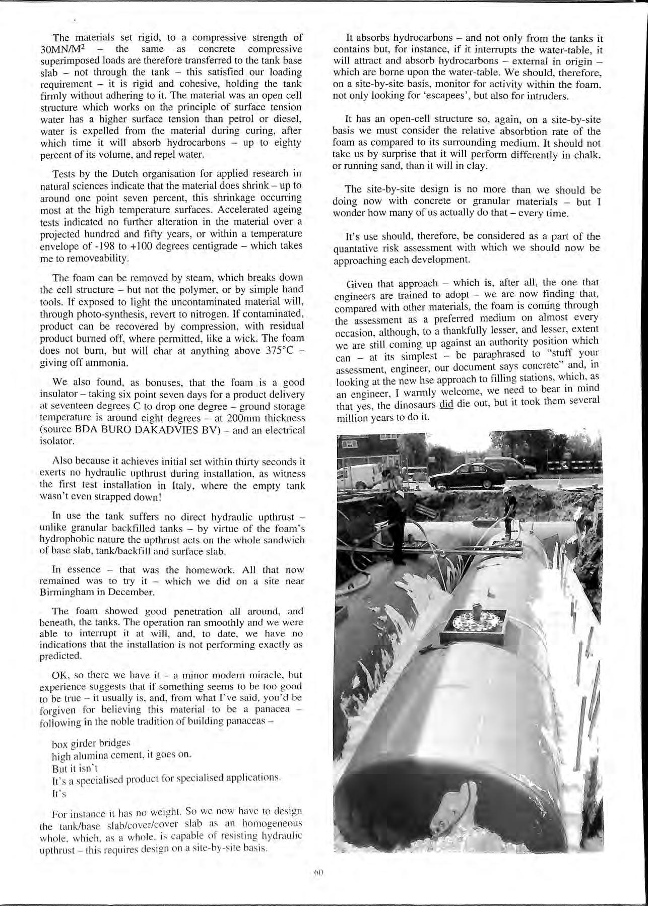
In essence that was the homework . All that now remained was to try it which we did on a site ne ar Birmingham in December.
The foam showed good penetration all around , and beneath , the tanks. The operation ran s moothly a nd we were able to interrupt it at will , and, to date , we have no indication s that the installation is not pe1fonning exactly as predicted
OK , so there we have it a minor modern miracle , but experience suggests that if so mething seems to be too good to be true it us ually is, and , from what I' ve said, you'd be forgiven for believing thi s mate1i al to be a pan acea following in th e nobl e tradition of building panaceas
box girder bridg es high alumina ce ment , it goes on.
But it isn ' t
It ' s a s pec iali se d product for s peciali se d appli ca tion s.
It 's
Fo r in stance it has no we ig ht. So we now ha ve to d es ig n th e tank/base s lab/cove r/cove r s lab as a n ho moge neo us w ho le , w hi c h, as a w hole , is ca pab le of res is ting h ydra uli c up t hru st thi s requires desi g n o n a site- by-s ite basis
It absorbs hydrocarbons and not only from the tanks it contains but, for instance, if it interrupts the water-table, it will attract and absorb hydrocarbons external in origin which are borne upon the water-table. We should, therefore, on a site-by-site basis, monitor for activity within the foam, not only looking for 'escapees', but also for intruders
It has an open-cell structure so, again, on a site-by-site basis we must consider the relative absorbtion rate of the foam as compared to its sun-ounding medium. It should not take us by surprise that it will perform differently in chalk, or running sand, than it will in clay.
The site-by-site design is no more than we should be doing now with concrete or granular materials but I wonder how many of us actually do that every time .
It's use should, therefore, be considered as a part of the quantative risk assessment with which we should now be approaching each development.
Given that approach which is , after all , the one that enaineers are trained to adopt we are now finding that, with other materials , the foam is corning through the assessment as a preferred medmm on almost every occasion althouah , to a thankfully lesser, and lesser, extent we are corr:ing up against an authority pos!,tion can _ at its simplest be paraphrased to assessment, engineer, our document says concrete m looking at the new hse approach to filling stat10ns , w_hich ,_ as an engineer , I warmly welcome, we to bear m that yes, the dinosaurs did die out, but 1t took them several million years to do it.
Before commencing, I would like to thank the APEA inviting me , on behalf of Prime Safe , to pres ent to this conference , it's the first time that the subject of an alternative to total tank replacement has received such wide spread expo sure.
I hope that I'm capable of rising to the challenge and that at the end of this presentation , you will feel able to add a new alternative to the growin a number of systems that b b provide environmental protection at existing petroleum forecourts
As many of you know I'm poacher turned game keeper and through my years of working within the retail industry , feel that I'm well pl aced to understand the chent s side , and judging by the re sponse to our product , this has been the case.
The issues that I intend to address are:
• Background to the introduction to the Prime Safe System of tank remediation.
• Cau ses of failure s in existing tanks and lessons.
• De scrip tion and benefit s of the Prime Safe Sy stem.
So what is it , the Prime Safe System , well it' s the process whereby e x isting underground fuel storage can be replaced by the installation of a new high performance GRP tank within the original storage tank or tanks The system is available either as a single skin , or a monitored double skin vers ion . Addi tionally 1'11 al so pro vide details on a number of way s the double skin system can be monitored and specifically the system offered by Prime Safe.
B efo re de scribing the system , why you may ask, do we need to replace a ny tank s, after all they don ' t leak. Well this is simply not the cas e , leaks from tanks are lower in number fr om lin es, but they do e xist and are currently only di scov e red afte r occurrin g Thi s is either by wetstock rec oncili ation or te stin g, they may even be accelerated as a res ult of some me thod s of te sting. Based on our experience a nd research far larger numbers are actually leakin g than are recog ni sed. This is becau se the le ak s are s mall and the s ys t_e m s e mploy ed to m o nitor the sto ck level s can't alway s d1 st rn g ui s h bet wee n general evaporative or metered lo ss es a nd leak losses .
Based on a sa mple of ove r J 30 tanks, that we hav e treate d , so m e 19% had throu g h shell pe rfo ration s and only 9 % had bee n kn ow n to be leaki ng prior to o ur in volv ement. T hi s tran s lates to so me 24 leaki ng ta nks w ith 83 ide ntifi ed leaks If the res ul ts of o ne exce pti o nal ta nk, with so me 50 h o les, are s tripp ed o ut it equ ates to 33 hol es in 2 3 ta nk s, a n ave rage of m ore th a n one pe r vesse l. T he mo re interes tin g fact is th at I J ta nks, fo un d to be leakin g , we re at si tes with no re po rted leaks a nd s o me of th ese sites had bee n the s ubj ect of rec e nt tank tes ting T hi s is yet furth e r ev ide nce that more tanks a re leakin g tha n ei the r s us pec ted or i demi fieel
T he q ues tion is how many tank s ar e leakin g, a nd the answ e r is a s ig n ificant n umbe r, if o ur fig ures are ind ica tive of !he prob le m , large numb ers of tanks may be leaking fue l !mla y . JOOO 's 1101 IOO 's .
So what is the cause, the answer is "through shell perforations" as a result of "corrosion ", mo re specifically "external corrosion" To date we have not found, as a result of our experience, one occurrence where internal corrosion been the cause of the failure. It is recognised this is d1'.ferent to the Swedish experience of internal corrosion failures but I can only report as we find I therefore reiterate that our experience is that leaks are caused predominately as the result of external pitting corro sion , acting upon the steel shell or w.elds of the underground storage tank. This expenence is partly borne out by the American experience and subsequent research into the causes of failure to 1900 tank s, found to be leaking. This concluded that over 75 % of tanks failed due to external corrosion 15 % to a combination of internal and external corro sion only 10% due to mternal corro sion . The incidence of internal corrosion is to be expected, because the american fuel s include additives that are recogni sed to increase the potential for internal corro s ion. The se fuel s are not currently sold in the UK , a nd the ab sence of internal failure s is therefore not unexpected.
With the se fa ctors in mjnd the des ign of our system wa s es tabli shed a nd le ad to the "TANK WITHIN A TANK" philo sophy Thi s effectivel y allow s th e original tank to contmu e to coITode without a de trimental effect on th e integrity of th e newl y form ed sys tem. Th e ori ginal tank is use d fo r ge ne ral stru ctural supp ort and fo rmin g of th e new ta nk.
. T hi s co mbin at ion pro vid es an ex tre me ly stro ng 111 sta ll at1o n up on compl et io n. T he in tro du c ti on of o ur sys tem will also preve nt fa ilure d ue to in te rn al cor ros io n, s hould thi s be fo und to beco me a s ig ni fica nt featm e of fut ure fa il u res due to change in fue l co mpo und s .
Returning to external corrosion, this does not, in our experience, result in the general thinning over the whole external surface. It is in fact localised pitting corrosion, often resulting in, even in the worst cases, less than 3-4% of the original tank structure being lost. This has little or no detrimental effect to the structural integrity of the tank.
Almost regardless of number and size of the perforations we are able to repair the tank and install the Prime Safe system. The worst tank treated to date had over 50 perforations in an area of approximately one square metre.
Most tanks with identified leaks only have one or a small number of defects and, as previously stated, almost all relate to the effects of external corrosion. Some are as a result of combining with other factors, such as fabrication defects or damage during installation, culminating in through shell perforations.
The types of corrosion are many and varied, the root cause of failure being exposure of the external tank shell to corrosion conditions. If the external shell of the tank remains protected from these conditions, long life should be expected. However to guarantee that 100% of the external surface of any tank is protected from such exposure is difficult to achieve and almost impossible to prove. This is catered for with new double skin steel tanks, for some 80% of the external surfaces, by the monitoring of the interstitial space. However if failure occurs, even with this system, the only course of action will be to remove or make the tank redundant. If this requirement is combined with the common practise of surrounding the tank in pea shingle the task of removal can be complicated and expensive.
Notwithstanding the scenario for double skin steel tanks, the situation with existing single skin tanks remains that leaks may only be detected after a leak to the environment or, as previously stated, at the time of testing. The opportunity for an alternative to total tanks replacement obviously has major advantages and the use of our system will therefore be mainly confined, for the foreseeable future, to the remediation of single skin steel tanks.
So what are the principle factors influencing if a tank is exposed to the effects of external corrosion. The quality of fabrication clearly has a role to play, as up to 12 leaks that we have observed, may have been as the result of poor welding or finishing of the tank during fabrication.
The installation phase is recognised and identified to be when the seeds for premature tank failure are sown. Traditionally single skin tanks are coated with an inexpensive bitumen coating, which can easily be damaged during installation or subsequently leached from the surface by exposure to motor fuels.
The remaining coating will not provide any significant protection in the leached areas and, if surrounded in sand, external c01Tosion can quickly commence. Indeed it is our experience that tanks surrounded in sand exhibit the most extensive levels of external corrosion. The tank with some 50 leaks turned out to be surrounded in sand and was only 15 years old.
However. as we all know. tanks have been summnded in concrete for many years and this corrosio.n_ protection even for unprotected This will be the case 1t tanks are carefully and correctly mstalled. however how do you know this. how do you know that conc_rete i: correct specification. That the 1s tree ot d.ay J0111t. cracks. contamination and is not ot reduced quality. as a result of ground water acting upon the fines prior to the
initial set. This never happens!, well, these slides clearly show examples of most of these problems, all at one site, this leads to external corrosion and tarik failure. This resulted in fuel being lost to the environment, causing financial loss and general inconvenience to the operating company and general public.
These problems are difficult to determine at existing sites because no economic method of testing tariks, to measure corrosion, has been perfected. Even if the tariks are known to be exposed to corrosion conditions, the timing of failure will be difficult to predict. Statistically any tank exposed to these conditions for over 15 years must be suspected. Incidentally the tank that failed here was again 15 years old. This is a significant bench mark, 15 years, above which a tank may fall at any time. Tank testing at 15 years may be more appropriate, based on our experience, as a testing date.
Finally the universal introduction of vapour balancing will not improve the situation if a tank is near to failure.
It goes without saying that any form of remediation must be able to withstand the influences of this feature of environmental control, the design of our system caters for vapour balancing and all current forms of tank testing.
Summary of key points:
• lOOO's of tanks leaking or close to failure.
• Internal preparation and inspection identifies more leaks than identified by other means.
• External pitting corrosion, acting on shell or fabrication defects, cause of failures observed.
• Quality of fabrication and installation significant factor in timing of failure.
• General structural performance of the tanks not significantly reduced even by extensive c01TOsion.
• Tanks at or over 15 years old are significantly more prone to leaks.
• Vapour balancing needs careful consideration at sites with older tanks.
The logical conclusion is that only remediation or replacements of tanks, above 15 years old, wil_I significantly reduce the incidence of actual leaks to the environment. The practicality and cost of such an exe:cise_ is and the targeting of resources towards high nsk_ sites most important. I suggest the following cntena for identifying high risk sites:
• Sites with any known tank leaks, past or present.
• Sites with steel tanks over 15 years old.
• Sites in environmentally sensitive locations.
• Sites that have not had any form of tank testing.
• Sites that have or are due to have stage Ib vapour balancing.
• Sites with tanks surrounded in sand.
• Sites with direct fills.
These methods will not identify all leaks hut may provide a sensible criteria for the successful direction of limited resources. providing the hcst value for money.
It was against this background that the Prime S stem of tank remediation was so as to provide y · and practical alternative to total tank an economic · lacement. The system involves the mternal preparation :ep · and treatment of existing underground fuel mspect10n · tanks with multiple layers of advanced resm storage d ank composites. The tanks are first emptied of an_ t s made safe followed by the removal_ the _hd or hds and disconnection and sealing of the existing pipework. These works can often be completed without the need for any costly civil engineering works. This phase takes _about a day, depending upon a number of tanks_ to be At the end of this stage a gas free certificate is issued and installation of the Prime Safe system commences. This consists in the inspection of the internal tank surfaces for defects if found the localised area is shot blasted and patch repaired. This process consists of layers of matting laminating resin applied to the defect The resulting repair ensures that a controlled internal be maintained and localised support and strength is provided for the subsequent processes. Following. th_is and possible repair procedure, the full remedrntion process is the undertaken.
This commences with the internal shot blasting of the tank and the further inspection of the surfaces for any defects and or identifiable leaks. If leaks are found the location is recorded and locally repaired, as previously described, prior to the application of the subsequent materials.
The first application is of a Vinyl Ester resin, this material combines high bond strength with excellent chemical resistant properties. This ensures that any future defects in the original tank will not result in delarnination through hydrostatic pressure or breakdown due to long term exposure to external chemical attack. This is followed by the application of a Vinyl Ester resin with flake and strand glass, providing a layer with high tensile strength, in effect the first structural layer of the new tank.
The next process is the application of the interstitial membrane and cross pillars followed by a further two structural layers and finally a layer of Vinyl Ester resin, providing the necessary chemical resistance for all current and anticipated fuels.
A number of major oil companies have tested the Vinyl Ester material, confirming that it meets their specification for resisting deterioration from all current and anticipated future fuel compounds. This material has also been successfully used for many years, by a number of group companies, to treat the internals of bulk fuel storage vessels. We have also inspected a number of our tanks after actual service and can confirm that no deterioration in surface quality and performance has been observed.
So, designed, tested, used for many years in similar environments and now checked for in service performance, we therefore have no hesitation in promoting the virtues of this product and the system as a whole.
The tank system is completed by the incorporation of interstitial tubes and terminal block. so as to provide the liquid connection to the remote monitoring system. This utilises two forms of monitoring, firstly liquid and secondly pressurised air. Prior to the introduction of the interstitial liquid. the void is used to vacuum and air pressure test the whole
The monitoring system is unique to Prime
incorporates two forms of monitoring the first static head with level detection and the second bemg apphed air pressure over the liquid head. This that the top of the tank is permanently tested to some 7psi for the of the working life of the remediated vessel. The _momto:ing system is provided for each tank, each system 1s with compressor, LED readout, header tank, pressure rehef valve and battery backup, capable of running system without mains power for extended periods, in reality many months.
The central control unit provides trickle charging of batteries during normal operation and can centrally record and monitor up to 15 tanks. This has LCD readout and a sophisticated display monitoring and alarm system that can be connected to remote monitoring facilities off site. Other forms of interstitial monitoring can be employed, vacuum, pressure or even hydrocarbon detection.
The Prime Safe monitoring system can also be adapted to monitor steel or GRP tanks either as part of a remediation project or as a stand alone installation. The monitoring system is remote from the tank farm, usually on the external of the sales or control building, therefore maintenance of this unit does not usually involve entry to the tank manhole/access way. The Control unit is located within the sales or control building so as to ensure the functions and alarm can be readily observed by site staff. The system require an annual maintenance inspection.
The added benefit of using the Prime Safe system is that sites can almost always remain open during our operation and many clients have selected this approach so as to minimise the impact to site revenue.
The Prime Safe System has been universally accepted by licensing authorities and operating companies as a solution that meets all current and future requirements for a long alternative to total tank replacement. To date every approached has approved the double skin system as suitable fpr remediation of existing tanks whether they have leaked or not, and, to the best of my knowledge, is the only system that is generally approved to remediate tanks that have leaked.
In our opinion it is the most cost effective and technically advanced system currently available, if the fully built up costs are taken into account. If these costs are combined with the costs of the permanent loss of trade, the cost advantage can be considerable.
These factors are sometimes ignored and only direct costs compared, however if all these elements are considered we are able to demonstrate significant cost savings over the replacei_nent alternative. This together with the fact that the system is double skinned for 100% of the internal shell area, will not corroded, is highly chemically resistant. The system has to meet the anticipated CEN standard for .mterst1t1al monitoring and chemical resistance, as to .new GRP tanks. This provides the user specifier with a compelling argument in favour of this course of action over replacement or redundancy.
In conclusion, I hope the foregoing provides you all with a new insight to the probability and consequences of leaking tanks and you agree with me that the Prime Safe System of introducing a "Tank within A Tank" lives up to the challenge of "New for Old".
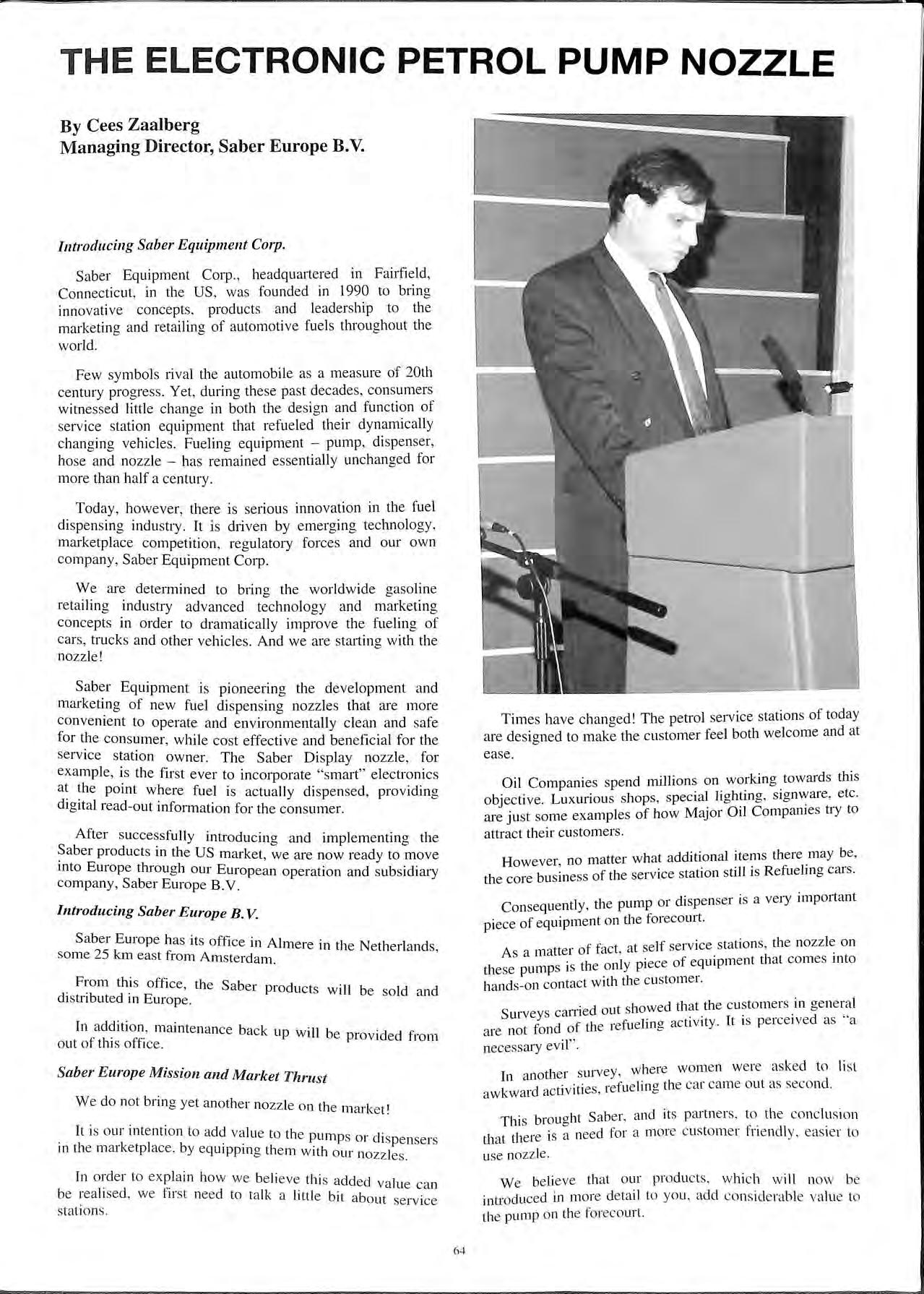
Sa ber Equipment Corp ., he adquartered in Fairfi e ld , Co nn ec ti cut , in the US , was found ed in 1990 to brin g inn ova ti ve con ce pt s , produ cts and leadership to th e m arke tin g and retailing of autom otiv e fu els throughout th e world.
Few symbols rival the autom obil e a s a measure of 20th ce ntury pro gress. Yet , during th ese pas t decades , consumers witn esse d littl e chan g e in both th e d es ign and function of ser vic e stati o n equipment th at refu e led their dynamicall y ch a ng in g vehicles Fu e lin g equipm e nt pump , di spen se r, ho se a nd nozz le - ha s re m ained e sse ntiall y unchan ged for mo re th a n h a lf a century.
To d ay, how e ver , there is se riou s innovation in the fu el di spe ns in g indu stry. It is driv e n by e merg ing technolo gy , m arketpl ace competition , reg ul atory forces and our own comp any , Saber Equipment Corp.
We are d e termined to bring th e worldwide ga so lin e re ta ilin g indu stry advan ced tec hn o lo g y and marketin g co nce pt s in o rder to dram ati ca ll y improve the fuelin g o f ca rs, tru cks a nd other vehicl es. And we are starting with th e no zz le !
S a be r Equipment is pion ee rin g th e de velopment and m ark e tin g of new fuel di spe n sin g no zz le s th at are m ore co nv e nient to operate and e nvironmenta lly clean and safe for the con s umer, while co st effective and beneficial for the servic e s tation owner. The S a ber Di splay nozzl e , for exa mpl e, is the first ever to in corp orate "s mart" electronic s a t th e po int where fuel is actu a ll y di spen sed , providin g di g it a l read out information for th e con s um e r.
After s uccessfull y introducin g and implementin g th e p ro duct s in the US m arke t, we ar·e now ready to mo ve mto Europ e through our Europ ean o peration and s ub s icliar y co mp any , S aber Europ e B.V.
S aber Europe has it s offi ce in Almere in the Netherland s, so me 25 km e as t from Am s terd a m
Fro m thi s offi c e , th e S a be r produ c ts w 1 ·11 b lei cl cl b cl· e so a n 1st n ute 111 Europe
In addit io n, m ai nte na nce back up w ill b d cl f · f I · f f e p1o v1 e 1o m o ut o t lt s o ice.
M
W e do no t bring ye t an o th e r nozz le o n th e marke t'
It is o ur inte nti on to acid va lu e to th e pump s 01 c1· . . . . 1s pe nse rs 111 th e ma1 ke tp lace , by equ1p p111 g th e m w ith o ur no zz les.
In o rd er to exp la in how we be li eve t hi s aclcl e d va ll cl f" 1e can be rea h se , we · irs t need to ta lk a li tt le bi t ab o ut se rv ice stat io ns.
Times have c hang ed! Th e pe trol service station s of today are designed to make th e c ustomer feel both welcom e and at ease.
Oil Compani es spe nd m.illi o ns on towar cl s thi s o bj ec tive . Lu xuriou s s ho ps, s pec ial lightmg, s1 g nware , e tc are ju st some ex a mpl es o f how Major Oil C o mpam es a y to a ttract their cu s tom ers
How ever, no matte r add.iti.onal the re n ".:y the core bu sine ss of th e ser vice station still 1s Refu e lm e cru s.
Cons equently , th e pump or di spe nser is a very impo rtant pi ece of equipment on th e forec ourt.
. f f t at se lf se rvice station s, th e nozz le o n A s a matte1 o ac , ' th ly pi ece of eqmpme nt th at co mes mto th ese pump s is e o n ha nd s-on contac t w ith th e c usto mer.
.· cl t s howed th at the c usto me rs in ge nera l S ur veys can1 e ou · · cl " cl f th ·efu elin cr act1v1ty. It 1s pe1ce 1ve as a ar·e no t fon o e 1 0 necessary ev il ". h i·vey w he re wo me n were aske d to li st Jn anot e1 s u ' ·cl. 0· u·es refu e lin a the car cam e out as seco nd aw kw a1 ac v 1 , e
TI · brmicrht S a ber, and it s partn e rs. to th e co nc lu s io n 11 S b f II th at th e re is a need fo r a mo re c usto m e r Tte nc y eas ie r to use noz z le.
We believe that o ur prod uc ts , w hi c h w ill now be intro du ced in more de ta il to yo u, acid co nsid e rab le va lu e to the pump o n th e foreco ur t.
we will introduce two new products on the European market;
The Saber Flow nozzle offers the company's revolutionary approach to customer friendly nozzles, featuring ergonomic design, lightweight materials and handling comfort, making refueling more convenient for customers and more profitable for station owners and operators.
With all the features of the Saber Flow, the Saber Display adds the excitement of digital read-out to the nozzle so that customers can read the volume and amount being displayed right on the nozzle.
The typical advantages of the Saber nozzles compared to currently available nozzles are:
The Saber nozzle had been designed specifically with the in mind. It is ergonomically designed, allowing for easier handling.
It also allows one finger operation.
Bearing in mind the surveys mentioned earlier, this will appeal very much to customers, in particular female customers.

is dt i.s lighter in weight than conventional nozzles. Also, it esigned to be in balance so that use is very easy.
from spage-age, fuel resistant plastic so that the sumi: is ;armer.to the touch in the winter and cooler in the This ?e mam body is made of glass reinforced nylon. can has been thoroughly developed by BASF and reason 1e stand any mechanical impact one can, within with xpect on a service station, including driving over it temperat;an The nozzle is designed to operate in a re range from -40°C to +65°C (-40°F to J50°F).
This means th t . the south of S . a can be used without any problems from pam till the north of Sweden.
The liquid crystal temperature range. display is also designed for this
· w performance
The almost stra· h . an excellent fi ig t fuel path through the nozzle provides ow performance.
The flow can b . latch positions. e iegulated with an old open latch with 2
This electronica]] fewer mechan· .. 1 Y enabled latching mechanism requires icc1 parts re l . . l . d "moother trigg ·: su tmg 111 ower mamtenance an ei operation.
In general the use f f ""' L·nr ional nozzle·. 0 parts than a '"''· '' ,. l!lt iesufts 111 higher rehah1lny and longer
The nozzle contains 2 intrinsically safe electronic sensing switches:
• Pressure Sensing Switch terminates fuel flow when the tank is full.
• Attitude Sensing Switch prevents the nozzle from operating when the nozzle is tilted up.
Both switches help to reduce accidental spillage during customer operation.
This spillage is of great concern to site operators. As you may know this spillage has lead to legislation in some European countries to install, at very high costs, fluid tight pavement.
In particular the pressure sensing switch h as advantage over the venturi type systems in conventional nozzles, because these nozzles are repressurised every time when shut off.
The nozzle has been designed with an integrated breakaway coupling that will separate in case of a "driveaway" (when the customer inadvertently drives away with the nozzle still in the fill pipe).
this happen, the nozzle simply requires an expensive new breakaway ring to be back in working order.
Microprocessor enabled communication system
'!be Saber Display nozzle includes a microprocessor, which allows for two way communication.
This opens up possibilities to install customer specific requirements.
In the US, where a significant amount of Saber nozzles been installed, customer surveys showed a very pos1t1ve reaction of users.
Th · · . e maJonty of the customers prefer the Saber nozzles findrng them easier to operate, more comfortable to handle and b tt · e er m appearance than the typical nozzle.
In a company like Saber and its innovative underlying key to success is the assurance quality m every aspect of our business.
Management sees the concept of quality spread as a large over every aspect of corporate activity, from selection of staff to product design, packaging. marketing and production.
strategic relationships with investors, vendors and workmg. have been based not only on the they provide. but also on our respect for quality Ill the services. products and relationships they offer.
Quality control and testing play major roles in bringing our design and products to the marketplace to assure our customers of long-term, problem-free, product perfonnance.
In today's competitive business we will out distance our competition through the innovative thinking we bring to product development and marketing, as well as our dedication to quality carried through the design, production, packaging and delivery of product to our customers.
Saber's quality system has been developed to meet or exceed the standards set by the International Organization for Standardization (ISO).
In four years Saber has become a recognised and highly regarded force in the supply of fuel dispensing nozzles to the gasoline retailing industry in the United States.
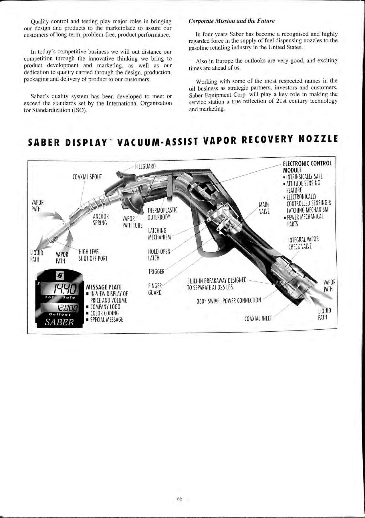
Also in Europe the outlooks are very good, and exciting times are ahead of us.
Working with some of the most respected names in the oil business as strategic partners, investors and customers, Saber Equipment Corp. will play a key role in making the service station a true reflection of 21 st century technology and marketing.


LEAK DETECTION SYSTEMS FOR DOUBLE SKIN TANKS.
LEAK DETECTION SYSTEMS FOR DOUBLE CONTAINMENT PIPES AND DISPENSER SUMPS.
TYPE 2000 INTELLIGENT TANK CONTENTS GAUGING SYSTEM.
INTERCEPTOR LEVEL ALARMS.
*BS 5750 Part 1 quality assurance.
*All systems meet relevant safety standards (EEx ia /IC for Zone 0 & EEx ib /IC for Zones 1 or 2).
*Systems accepted by LFCDA.