AP EA emt

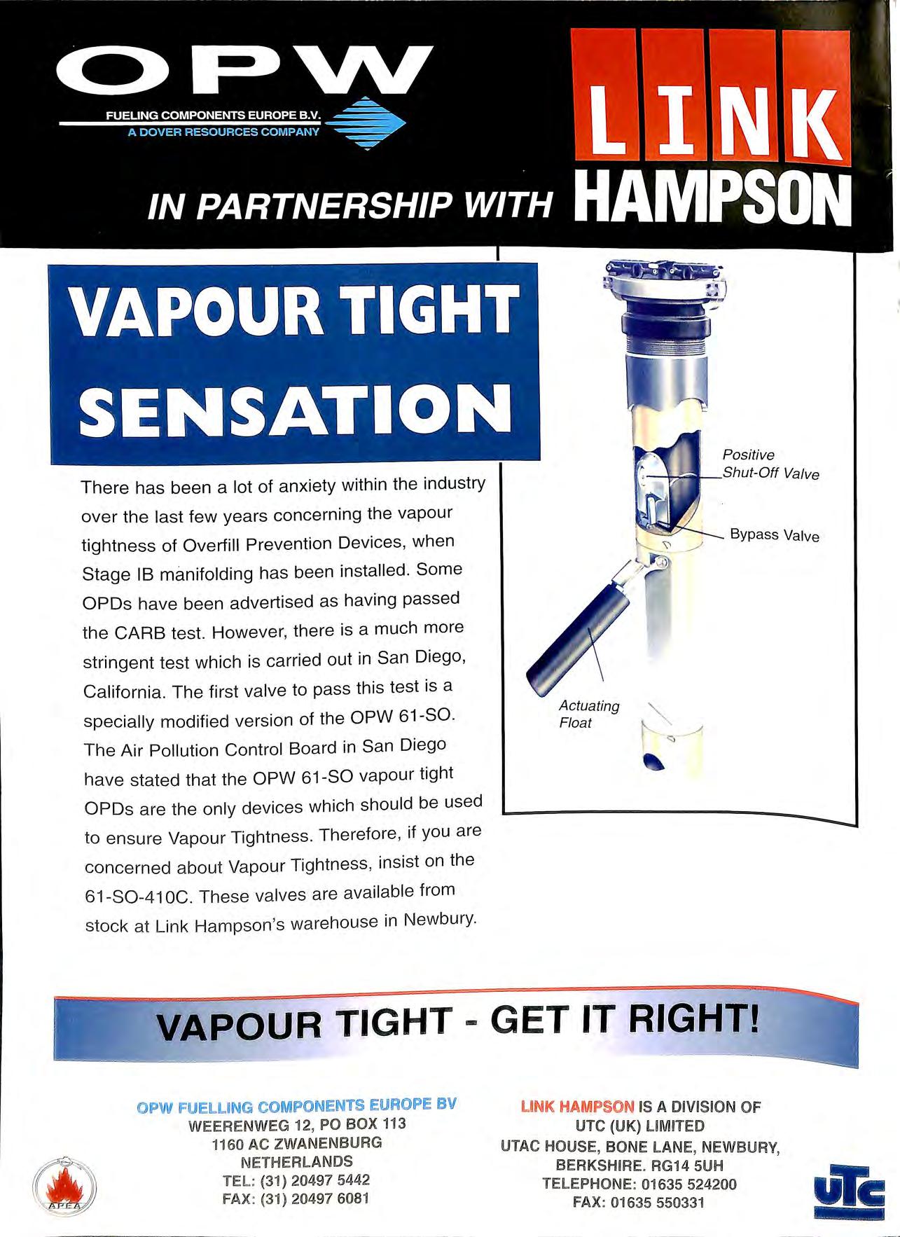
There has been a lot of anxiety within the industry over the last few years concerning the vapour tightness of Overfill Prevention Devices, when Stage IB manifolding has been installed Some OPDs have been advertised as having passed the GARB test. However, there is a much more stringent test which is carried out in San Diego , California. The first valve to pass this test is a specially modified version of the OPW 61-SO. The Air Pollution Control Board in San Diego have stated that the OPW 61-SO vapour tight OPDs are the only devices which should be used to ensure Vapour Tightness. Therefore , if you are concerned about Vapour Tightness , insist on the 61 S0 41 OC . These valves are available from stock at Link Hampson 's warehouse in Newbury.
PETROL FILLING STATIONS:


This is what 0.1 % fuel loss represents to a typical forecourt operator. Most sites are losing many more tim es this amount each yea r!
Petro Vend's SiteSentinel forecourt monitoring system guards against wetsrock loss, leaks , theft, short deliveri es to mention just a few!
It tell s you through acc urate printouts and easy to unders tand graphical analysis, not only how much fuel yo u are lo sin g on a day by day basis but indicates where in th e sys tem the lo ss is.
It is a modular sys tem that can be tailored to yo ur prese nt ne eds and ex panded later.
SiteSentinel is alread y proving a wi nn er in America because
is easy to understand and use, and pays for itself in rea l savings .
PO Box 2, Hadleigh, Suffolk, IP7 5SF, UK Tel: 01473 828539 Fax: 01473 828538
As Editor I have great pleasure in publishing in this edition of the Bulletin the papers given at the annual Conference in Birmingham in September. All of the papers were extremely well presented and I thank on behalf of the Association those speakers who worked so hard in making this such a professional presentation.
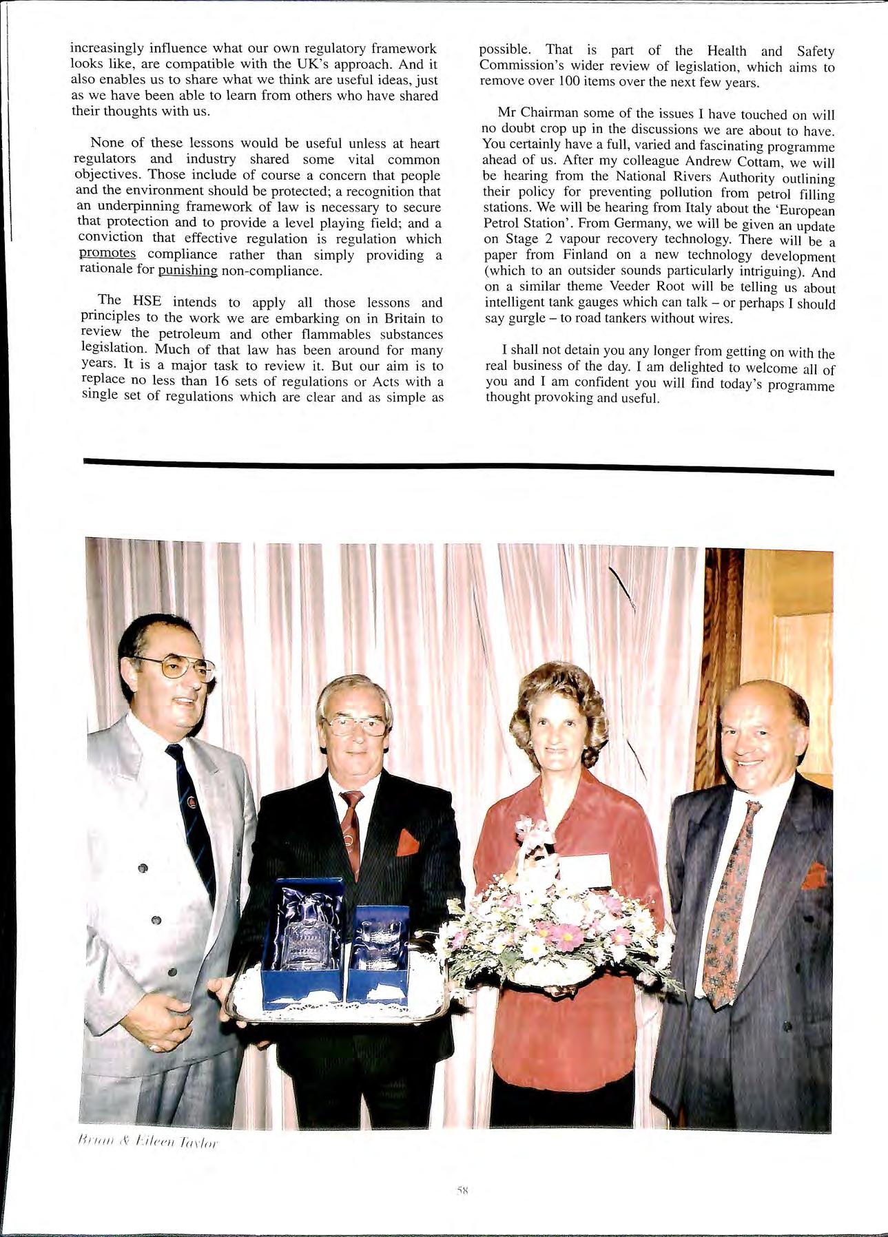
At the annual pre-conference dinner the Association had pleasure in honouring Brian and Eileen Taylor for their hard work over the years on behalf of the Association and they were presented with cut glass decanter, glasses and a floral bouquet for Eileen.
There was once again generous sponsorship from sections of the Industry who made this event a success and most importantly an enjoyable two days. The APEA would like to thank the Petrol Pump Manufacturers Association, Elaflex, Petrovend, APT, for their specific assistance.
And third, because it gives me a chance to say a few words about regulation and the role of the re<>ulator in general, as we see it in Great Britain, and about health and sa_fety in particular, based on our experiences with that project and the lessons we can learn from it.
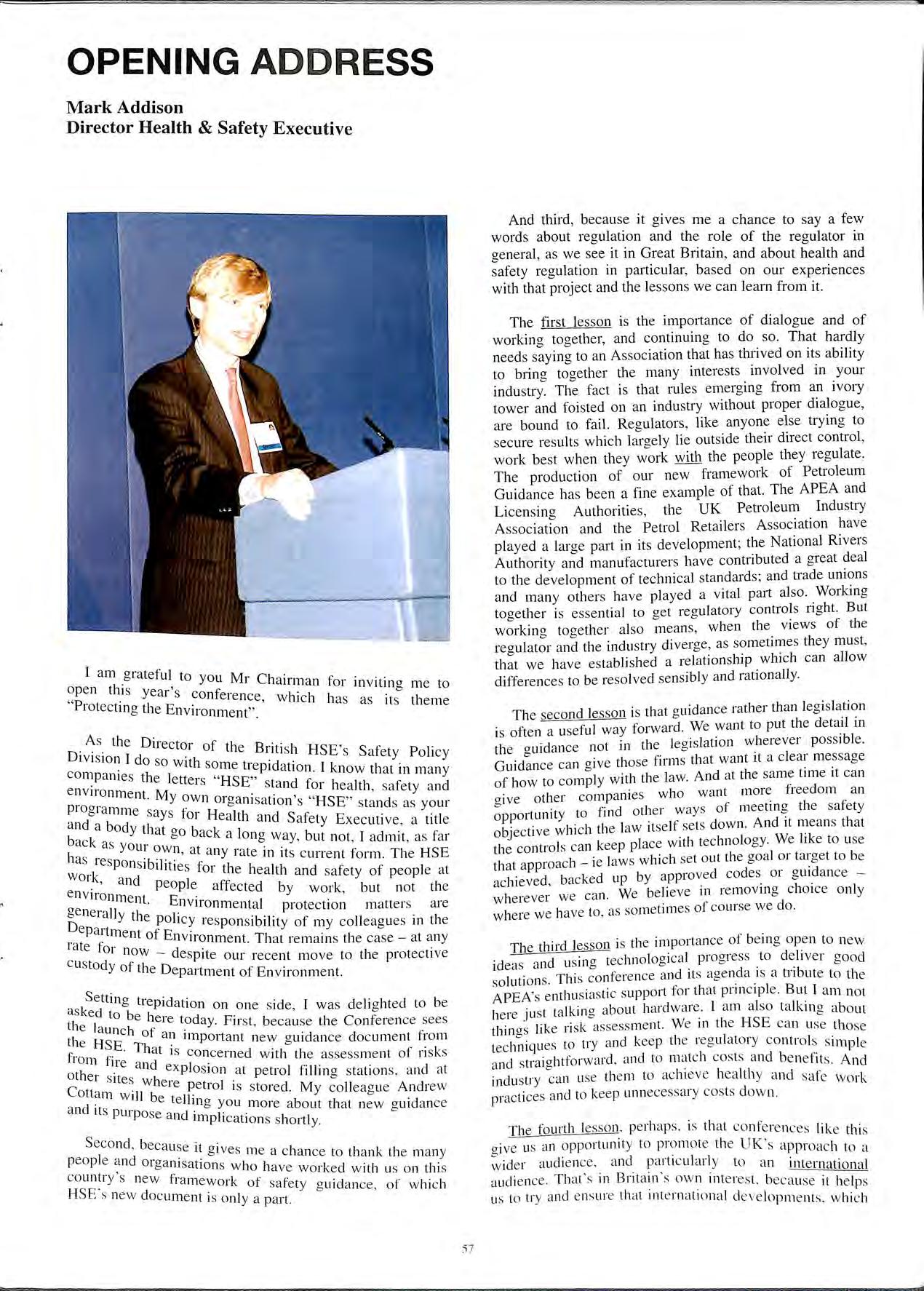
I am grateful to open this ·' you Mr Chairman for inviting me to "P. yea1 s conference wl · I I 1otect h ' lIC 1 ms as 1"ts tl1e111e mg t e Environment"
the Director of the B .. . ' D1v1sion I do so with nt1sh HSE s Safety Policy co some trepidation I k h mpa111es the letters "HSE" < • • now t at m many environment M stand for health safety and · · Y own organisation' "HSE" ' piogramme says for H 1 h s stands as your and a body that 00 b kea t and Safety Executive , a title back as youi· ow0 ac a long way, but not , I admit as far h n at any · t · · ' as responsib"l· ' ia e 111 its current form. The HSE I it1es for the h Ith d work and 1 ea an safety of people at e affected by work , but not the generally tll · 1_nvironmental protection matters are D e po icy resp "bT f epartment of E . . ons1 1 1ty o my colleagues in the rate for nvu onment. That remains the case at any now despit custody f 1 e our recent move to the protective 0 t le Department of Environment.
Setting tre id asked to b 1 P ation on one side, I was deli<>hted to be I e lere toda F b o t le launch f Y· 1rst, ecause the Conference sees the HSE an important new guidance document from from fire a 1dat is concerned with the assessment of risk s < n exp! · . .. . . other s ites wh oswn at petrol hllm<> stations and at ere pet I o ' Cottam will be t Ir IO is strn ed. My colleague Andrew and it s purpo se m g you more about that new guidance tmphcat1ons s hortly.
Second bec·' use ·r ' " 1 °1ves , I. people and or<>anjsat· 0 me d c lclllc e to thank the many o < ion s who hav e ·k cl co untry 's new fra ·k wo1 e with us on this mewo1 of safety · I HSE' s ne w clocumen t· , 1 gu1c ance, of which 1s on y a part.
The first lesson is the importance of dialo<>ue and of working and to do so. That hardly needs_ saymg to an Assoc1at1on that has thrived on its ability brmg together the many interests involved in your mdustry. The fact is that rules emerging from an ivory tower and foisted on an industry without proper dialogue, are bound to fail. Regulators, like anyone else trying to secure results which largely lie outside their direct control , work best when they work with the people they regulate. The production of our new framework of Petroleum Guidance has been a fine example of that. The APEA and Licensing Authorities, the UK Petroleum Industry Association and the Petrol Retailers Association have played a large part in its development; the National Rivers Authority and manufacturers have contributed a great deal to the development of technical standards; and trade unions and many others have played a vital part also. Working together is essential to get regulatory controls right. But working together also means, when the views of the regulator and the industry diverge , as sometimes they must, that we have established a relationship which can allow differences to be resolved sensibly and rationally.
The second lesson is that guidance rather than legislation is often a useful way forward. We want to put the detail in the guidance not in the legislation wherever possible Guidance can give those firms that want it a clear message of how to comply with the law. And at the same time it can give other companies who want more freedom an opportunity to find other ways of meeting the safety objective which the la w itself sets clown. And it means that the controls can keep place with technology. We like to use that approach ie laws which set out the goal or target to be achieved, backed up by approved codes or guidance wherever we can. We believe in removing choice on ly where we hav e to , as sometimes of course we do.
The third lesson is the importance of be ing open to new ideas and using tec hnological progress to deliver good solutions. Thi s conference and its agenda is a tribute to the APEA' s enthusiastic s upport for that principle. But 1 am not here just talking about hardware. I am also talking about thing s li ke ri sk assessment. We in the HSE can u se tho se tec hniques to try and keep th e reg ulatory controls s imple a nd straightforward , and to match costs and b e nefit s. And indu s_try can use th e m to achieve hea lth y and safe work practices and to keep unn ecessary cos ts cl ow n.
The fourth lesso n , pe rh aps, is that conferences li ke thi s a 1ve us an opporturnty to promote th e UK"s ··ipp11 I t ' Laci o a wider aud1e11ce. a nd particularly to an int · 1 · TI · · B · · , e 1nat1ona audience. iat s Ill nt arn s own inte rest be"l . h 1 , , , · · c, use tt e ps us to u y cllld e nsu1 e that 1nt e 1n dt1onal cl e ve l() j) n 1 I· I 1 e n s. w 11 c i
increasingly influence what our own regulatory framework looks like, are compatible with the UK's approach. And it also enables us to share what we think are useful ideas, just as we have been able to learn from others who have shared their thoughts with us.
None of these lessons would be useful unless at heart regulators and industry shared some vital common objectives. Those include of course a concern that people and the environment should be protected; a recognition that an underpinning framework of law is necessary to secure that protection and to provide a level playing field; and a conviction that effective regulation is regulation which promotes compliance rather than simply providing a rationale for punishing non-compliance.
The HSE intends to apply all those lessons and principles to the work we are embarking on in Britain to review the petroleum and other flammables substances legislation. Much of that law has been around for many years. It is a major task to review it. But our aim is to replace no less than 16 sets of regulations or Acts with a single set of regulations which are clear and as simple as
possible. That is part of the Health and Safety Commission's wider review of legislation, which aims to remove over 100 items over the next few years.
Mr Chairman some of the issues I have touched on will no doubt crop up in the discussions we are about to have. You certainly have a full, varied and fascinating programme ahead of us. After my colleague Andrew Cottam, we will be hearing from the National Rivers Authority outlining their policy for preventing pollution from petrol filling stations. We will be hearing from Italy about the 'European Petrol Station'. From Germany, we will be given an update on Stage 2 vapour recovery technology There will be a paper from Finland on a new technology development (which to an outsider sounds particularly intriguing). And on a similar theme Veeder Root will be telling us about intelligent tank gauges which can talk or perhaps I should say gurgle to road tankers without wires.
I shall not detain you any longer from getting on with the real business of the day. I am delighted to welcome all of you and I am confident you will find today's programme thought provoking and useful.
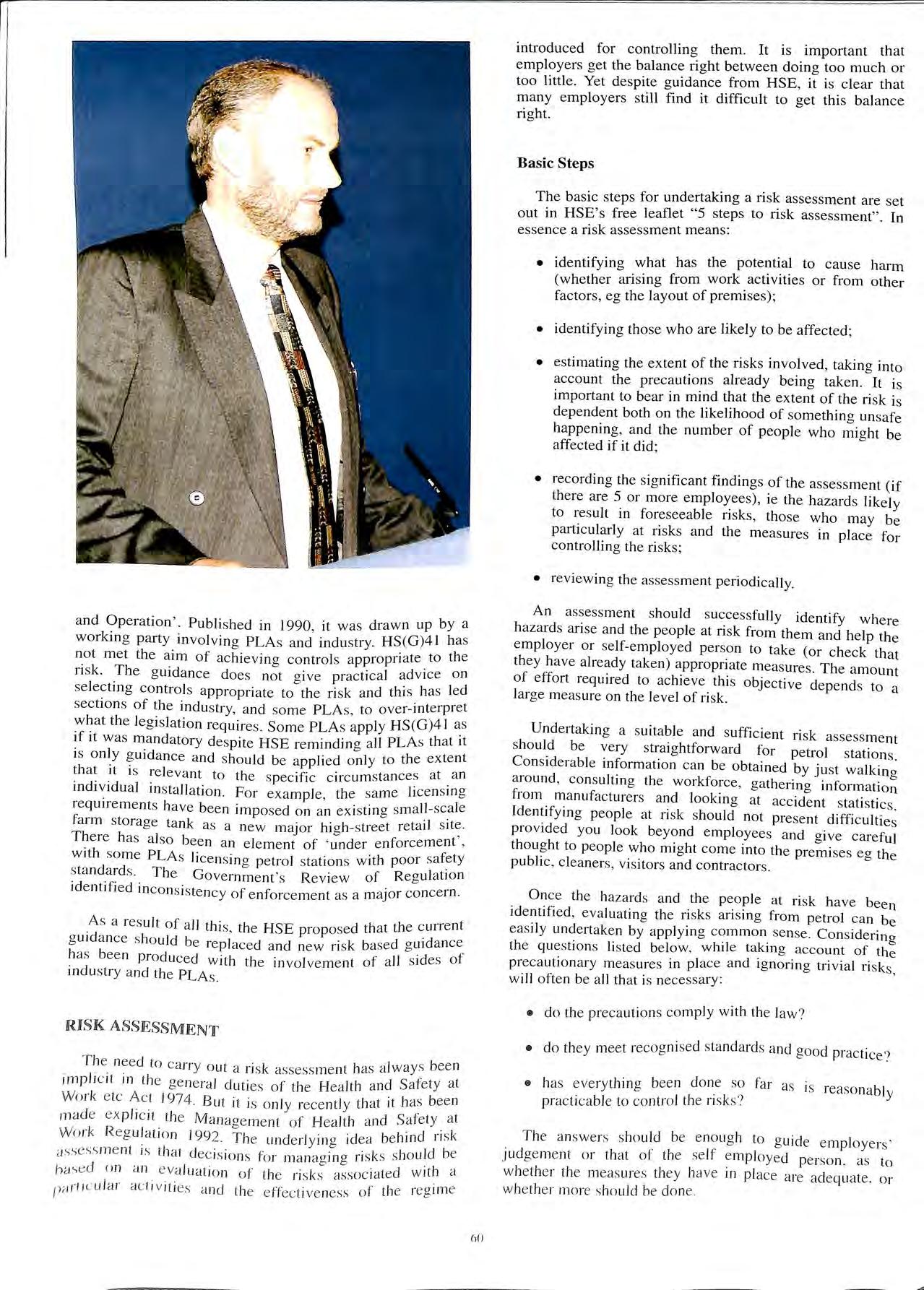
 Dr Andrew Cottam Head, Flammable Substances Policy Section Health and Safety Executive
The APEA conference sees the launch of the Health and Executive's (HSE) new guidance on the safe d1spensmg of petrol as a fuel. While this paper is titled ·a new approach', what the guidance does is reinforce existino good practice rather than introduce anything new.
Key features of the new guidance are that:
• it to existing as well as new sites. not only retail fillmg stations but also farms, commercial sites '
• it is based on the HSE'. 5 s . s teps to Risk Assessment;
• it provides .a methodology to aid analysis of the hazard and nsks a d ·d ·f· · · · n 1 ent1 1cat1on of necessary safety controls at sites where petrol is dispensed as a fuel.
The move to a ri k b . d h s ase approach represents a step c ange for Petroleum Off h .· 1cers, t e petroleum industry and site) alike. To help the transition and to allow ear Y evaluation of ·t · · '. ' .d 1 s impact, we propose to implement the gu1 ance by means f · ·1 · r · o d p1 ot m tour areas of Great Britain, sta1 tmo 111 Octob 199" N . f II "' er ·'· at1onal publication will then o ow early 111 1996.
use of risk assessment for deciding whether a particuhr ··t t. of . ' si ua ion presents a problem and 1f so the amount h resources that should be spent to tackle it is a of our times. The need to assess risks is now an integral part of the decision-making process, and is mdeed central to the British reoulatory framework for h Ith · "' ea and safety, eg for ensuring that those who create nsks to man and the environment take the necessary to eliminate or reduce them to levels tolerable to society.
In my paper I would like to:
• describe the 1 · I t' h H o e o t e ealth and Satety Executive:
• outline the b·1s1·c ·· · I 1· · k I '· p1111c1p es o · ns assessment anc consider their 1· · · app 1cat1on to petrol filling stations:
• dispel the notion that risk assessment is a complicated and burdensome process.
The aims of the HSE are to protect the health, safety and welfare of employees, and to safeguard public, who may be exposed to from actlVlty. The HSE's role is to see that nsks from busmess _are controlled effectively, in ways that allow for technological progress and pay due regard to cost. HSE liaises with all whom its work affects; and seeks to promote manaoement of health and safety, through a systematic to identifying hazards and assessing and controlling risks.
The responsibility for workplace .health. and is placed upon those directly engaged m mamly employers, but also the self-employed, supplied The Executive are there to inform, stimulate and gmde holders, and others concerned with health and safety, and m particular to:
(a) define standards;
(b) romote compliance with the He_alth. and Safety at etc Act 1974, and other leg1slat1on such as the Petroleum (Consolidation) Act 1928.
. t 1 is subiect to licensing under the Keepmo pe ro · · J k "'C 1·dation) Act 1928, winch see ·s to protect Petroleum ( onso t f. d the public from the dangers of ire and employees an . . . f Ir I explosion. HSE has policy respons1b1ltty ?r Jing 1e · d . of hi ahly flammable ltqu1 s. me udmg keepmo an use "' d 1· "'R ·"bility for licensing an en orcement of petrol. espons1 -: h . b b d' I • ty hw is however. 111 t e mam y o 1es petro eum sa1e ' · · L., .· A h .· · outside the HSE; the utd011ties PLAs). PLAs have wide d1scret10.n.aiy un er the 928 Act to set whatever co'.1citt10ns of licence t.hey ··d iiecess·iry to ensure safety. Whtie HSE provide:-. const e1 · ·' advice centrally to PLAs. 1t cannot direct the act1v1t 1es or individual Authorities.
The PLAs are the Fire and Civil Defence Authorities in the former Metropolitan areas. Country Council Fire nr Trading Standards Departments elsewhere in England and Wales :md the Regional and Island Cl)UtKils in Scotland.
In order to encourage consistent enforcement or licensing across the country. HSE produced the guidance document HS(Gl4 l ·Petrol Filling Stations Construction
and Operation'. Publi shed in 19 90 , it was drawn up by a working party involving PLAs and indu stry. HS(G)4 I has not met the aim of achieving control s appropri ate. to th e risk. The g uidance doe s not give practi cal advi ce on se lectin g controls appropriate to th e ri sk and thi s has led sectio ns of the indu stry, and so me PLAs , to o ver-interpret w ha t the legi s lati o n requires. So me PLA s apply HS (G )4 l if it wa s mandatory d es pite HSE reminding a ll PLA s th at it is o nly g uid ance and should be applied o nl y to the extent that it is re leva nt to th e s pecific circ um s ta nce s at an individu al in s tallation. Fo r exa mpl e, the sa me licen s mg requirements have bee n impo sed on an ex istin g s ma ll -sc_a le farm storage tank as a new major hig h- street reta il There has al so been an e le me nt of ' under e nfo rcement , with some PLA s licen s in g petrol stat ion s with poo r s ta nd a rd s. The Government' s Rev iew of Reg ul a t10n identifi ed inco ns is tency of e nforce me nt as a major co ncern.
As a res ult of a ll this, th e HS E pro po sed th at th e current g uidance s ho uld be rep laced a nd new ri sk based g uid ance ha s been prod uced with the in vo lve me nt of all s id es of indu s try a nd the PLA s.
T he need to carry o ut a ri s k assessment has a lways been impli c it in the genera l duties of the Hea lth an d Safety at Wo rk e tc Ac_t 1974. But it is o nl y rec e ntl y that it has bee n made exp li c it the Manaoement o f Hea lth a nd Safe ty a t Wo rk Regu la ti o n 1992. T he underlying id ea behind ri sk assess m e nt 1s that decision s fo r man ag in g ri sks s hould be hased on an eva lu ation of the ri s ks associated w ith a l'" r1i c u Jar activ iti es and th e e ffe c tiveness of the regi me
introduced for controlling them. It is important that employers get the balance right between doing too much or too little . Yet des pite guidance from HSE, it is clear that many employers still find it difficult to get this bal ance right.
The basic steps for undertaking a risk assessment are set out in HSE's free leaflet "5 steps to risk assessment" . In es se nce a risk assess ment mean s:
• identifying what has the potential to cau se harm (whether arising from work activities or from other factors, eg the layout of premi ses);
• identifying those who are likely to be affected ;
• estimating the extent of the ri sks involved, taking into account the prec autions already being take n. It is important to bear in mind that the extent of the ri sk is dependent both on the likelihood of something un safe happening, and the number of people who might be affected if it did;
• recording th e significant findings of the assessment (if th ere are 5 or more employee s), ie the hazard s likely to re sult in foresee able risks, those who may be particularly at ri sks and the measure s in place for controlling the risks;
• reviewing the assessment periodically.
An assess ment should successfully identify where ha zard s ari se and the peopl e at risk from them and help th e employer or self-employed person to take (or check that they have already take n) appropriate measures. The amount of effort required to achieve this objective depends to a large meas ure on the level of ri sk
Undertaking a suitable and sufficient ri sk assessment sho uld be very straightforward for petrol station s. C o nsiderable inform ation can be obtained by ju st walkino around, con s ultin g the workforce , gathe rin g fr om manufacturers and looking at ac cide nt stati stic s Ide ntifyin g people at risk should not prese nt provided you look beyond employees and give careful thou ght to peo ple who mi ght come into the pre mi ses eg the public , clean ers, visitors and contractors.
On ce the ha zard s a nd th e people at ri s k hav e been identifi ed, evalu ati ng the ri sks arising from petrol can be eas ily undertaken by appl yi ng co mmon se nse. Con s id erin o the qu es tion s li sted below, w hjle taking acco unt of th: preca uti o nary meas ures in pl ace and ig n01 in g tri vial ri s ks, will often be a ll that is necessary :
• do the preca ution s co mpl y with th e law ?
• do th ey mee t recog ni sed s tandard s and good practice?
• has everyt hin g bee n don e so far as is reaso nabl y practicable to con tro l the ri sks?
T he a nswers s ho uld be eno ugh to g uide em pl oye rs' judge me nt o r tha t of the se lf emp loyed perso n. as to w he ther the measures th ey have in place are ad eq uate. or whe th e r mo re s hould be don e
The new guidance draws on HSE's widely accepted '5 steps to Risk Assessment' and will assist petrol stations operators in meeting their obligations under the management of Health and Safety at Work Regulations 1992. The guidance should lead to PLAs setting licensing conditions appropriate to the risks at individual petrol stations, thus avoiding unnecessary burdens on business. The '5 Steps' in the new guidance are:
Step 1: take a fresh look at the site, its design, operation and surroundings and identify where a fire and explosion hazard may exist.
Step 2: for each area of the site and operation consider what could go wrong and who could be affected.
Step 3: your findings from step 1 and decide if the precautions are enough to guard against anything going wrong, or if more should be done.
Step 4: record your findings.
Step 5: consider when you will need to review the risk assessment.
The ?uidance, however, goes beyond the '5 Steps' by develop11!g an approach for ranking the hazards and risks from vanous operations involved in dispensino- petrol· it is only a qualitative approach. It provides the' user with examples of the main control options, suitable for the level of hazard and risk identified TI I d . d I . h 1ose mvo ve 111 eve opmo- t e gui'd b 1 ance e 1eve that this structured is essential to securing greater consistency in the application of safety st d ·d an ai s at sites where petrol 1s dispensed as a fuel.
. To assist in completing Steps I, 2 and 3 of the '5 steps' p10.cess, a suggested method is given for identifying the mam_ of concern and some of the options for contiollmg them Wh'l th · • 1 e e1e 1s no general formula tor nsks, .the guidance offers a method to assist in ecision It is important to note that it is not a comprehensive asse · I · · · ssment met 10d. In using it. you will <1lso need to weio-11 tl l'k l'l c up 1e 1 ·e 110od of somethmo- 0-01110wl iong and the number of people who could potentially 1armed All f h . · · o t ese factors will vary from site to site.
. guidance looks in turn at the main elements of a site. and venting, storage, pipework systems. and chspens1110- 'd ·1· · · · · · c• I ent1 ymg the key concerns and g1vmg examples of the different control measure to consider. The methodology should only be used as part of the 5 steps process and will not cover all situations but may help in identifying the main areas to be considered.
f _For each element you are asked to consider the potential at the site. This provides a weighting factor, which Is combmed . h h . Wit t e scores given for each element of the operation The sco ·· · · · d' I · · 11ng system 1s des10-ned to m 1cate t 1e main areas h · h c . . ' w 1c need to be addressed. Sites differ and the sconng system . . . . . · cannot cover every type of s1tuat1on and cannot be hke11 as · l · · 1· ' · d precise ref ect1on of the deo-ree o hazard or risk It 111·1y hel l bi' I · · ' p. 1owever, to esta 1s 1 pnont1es. the total score calculated to note that the lists in the guidance rather than exhaustive. There may be other site operations that will need to be considered and other types of equipment. work systems and control
measures not listed. Judgement will be needed in deciding what is necessary and feasible for the particular site and its circumstances.
When selecting control measures it will be necessary to consider what can be done in light of the circumstances of the site. Where a hazard can be eliminated by changing the physical layout of a site this may remove the need for further action. However, it is not always necessary or possible to achieve the ideal and providing the a.rpropriate controls are in place, it is possible to run even a high site safely. The guidance gives some examples of opt10ns from which control measures may be selected to address the hazards and risks identified. There may also be other control measures not listed in the guidance.
The new o-uidance is intended to result in greater c · · th way in which PLAs proport1onahty and consistency m e apply the law the transparency about what petrol ' PLA It should help av01 operators may expect from s. who are able to unnecessary burdens on operators f . k demonstrate they have achieved a sensible balance o and control and should lead to a fair and proper approac to enforcement by PLAs.
· h t risk assessment is There is a common percept10n t a 1 . d d best left to experts. somethino- that is complicate an f h ths hope thatI have been able to dispel 0 t 011se · h ·e hazards aI e we ' For petrol stat10ns, w .e1 d d common-sense assessing Iisk is a strai.ghtforw;r t :;n usino- available process and u;E far an guidance and gmdelmes Jwm · stimate of particuJm· proceeds bey?nd. a complexity of the hazards and s1tuat10ns will d P 1 eh data and f · 'k resent and 1ow mu site, the degree o ns. P 1 ble Here ao-ain criteria · b t the nsks 1s avai a · "' informat10n a ou d1 · 1· b 1 in these circumstances it published by HSE shoul 1e p. u t lk to your local will be particularly important to a Petroleum Officer.
·ci·i'pti've It seeks to make ·d · not pies · The new gm ance 1.s ·e· of' tile hazards from their 'bi f · sites awai those respons1 e 01 • · 1 ·n line with their legal 1d enable t 1em. I d operat10ns di . f. 1 ·dei1t1·f')'ino assess mg an d t · p1"1c1Ice o c• obligations. a th large number of sites involved controlling nsks. 1t. e. equipment, site, design, considerable exist. The contents of the systems and Pb ed as a guide and the reader document can on y e us. 't will need to use discretion m applymg I •
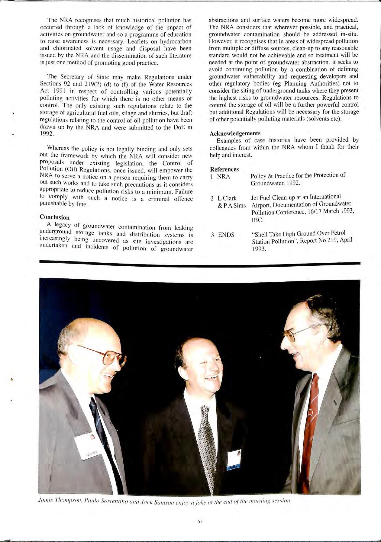
ber of •Jeople have been involved in A large num t .• · I n 'W o-uid'lllce and I would hke to thank <11! develop11rn t le t: "' ' 11 J'k I h· v, contributed In particular I wou ( 1 e to those w 10 d e , I" S . . k Al Rob 'i·ts Eddie Furniss, John H.1zt:I( ( ,m, , tua1 t than an e · · , Howell. Tom Mellish. Phil Monger. Doug Russdl. D.t\e Pumford. Jack Samson. Jamie Thompson and Roger Marris.
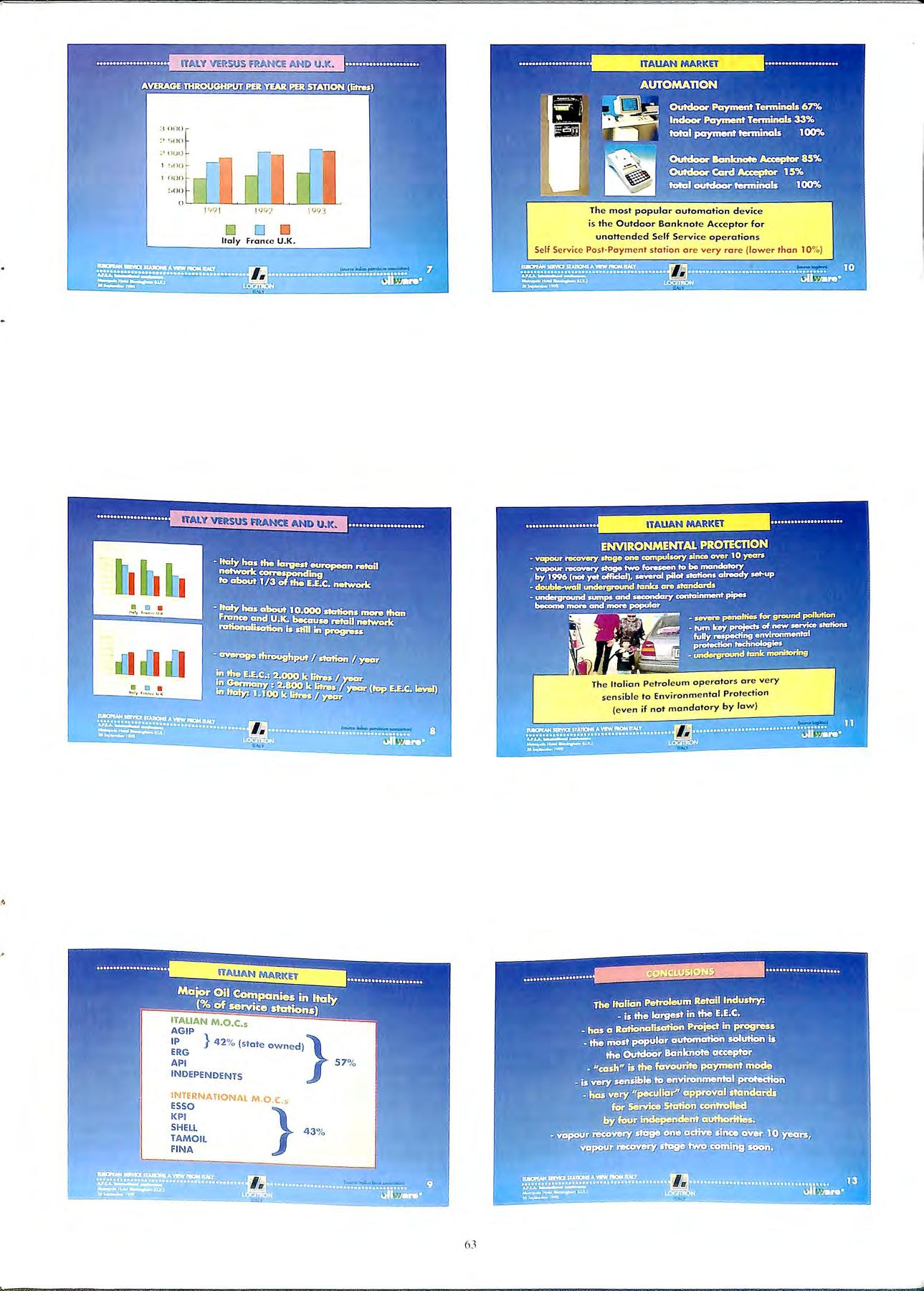
order of importance in the UK, the Chalk, the Triassic sandstones and the Jurassic limestones. Minor Aquifers may be important locally for water supply and may, like Carboniferous limestone s. support river baseflows to a high degree, but they comprise a wide variety of rock types. Some of these are less vulnerable to pollution than others by virtue of their physical characteri stics. The Coal Measures , for example, consist of interbedded sandstones and shales, as well as coal seams. The sandstone beds are often utilised for local water supplies but the low permeability shales and mudstones that overlie them can act to protect against pollutants infiltrating from the land surface.
Rocks which do not support large ab stractions and where rainfall is more likely to run off to watercourses than infiltrate to groundwater are termed Non-Aquifers. Some are capable of supporting small abstractions (farm supplies for example) but their low permeability characteristics largely preclude any interest in groundwater as a significant usable resource.
In England and Wales approximately 35% of our potable water s upply is pumped from underground strata. Groundwater is a cheap, largely uncontaminated water re so urce and of vital national importance. Groundwater also forms a s ubstant ial part of the dry weather flows in our rivers and s upport s many wetland habitats It s protection from pollution is a principal concern of the National Rivers Authority (NRA) but, becau se groundwater is eve rywhere benea th our feet , protecting it aga in st all so urce s of pollution is a matter of influencin g land use and spec ifi c activities o n th e surfa ce. The NRA has little direct control over many act ivitie s and mu st rely on the powe rs of other bodies and the establishment of good practice s withm indu st ry to alleviate pollution. To help in this task it rece ntly publi shed its policy o n Groundwater Protection which se ts out a framework by which it , and others , may Jud ge pote nti a lly polluting activities a nd miti gate agam st the ri s ks Pollution of aroundwater by non- aq ueou s phase liquid s (NAPL), hydro carbo ns and chlorinated so lven ts, is co mmon in urban indu strial areas which are und e rl ain by aquifers a nd is increas in gly being reco gni sed in more rural situ at io ns from iso lated point sou rces Und e tec ted leakage from the storage and distribution of th ese s ub stanc es fr o m und e rground storag e tank s is one of th e prin c ip a l reaso ns why suc h pollution is wid esp read.
Gro und wate r as a usab le water reso urce is fo und in rocks c a ll e c.J aqu ife rs. T hese ma y co nve ni e ntly be subdivided into M a.1or A quife rs and Minor Aquife rs Majo r Aq uife rs are rnck .., w hll'h a re capab le of sto rin g and hav ing pumped lr" m tht> m . -. 1gn ifi ca nt quant iti e.-; of wa te l". T hey are 11 np 11rt ;rn1 -. rr;i 1cg 1c all y lo r wat e r s uppl y T hese ro c ks are . 111
The Major Aquifers outcrop mainly in the South and East of England and in the Midland s. Much of Wales and the North and West of England are formed from NonAquifers or Minor Aquifers. This is reflected in the regional usage of groundwater whereby around 80 % of the public water supply of the NRA Southern Region is derived from groundwater whereas in the Welsh Region the figure is 2%
Although groundwater may not be an important resource in Minor Aquifers and Non-Aquifers, it is still present within rocks and can move toward s discharge points such as springs or seepages into watercourses and wetlands. Hence groundwater can also be the pathway by which pollutants move from their source to the environment target.
Groundwater in England and Wales is generally of good qua Iity. It is under threat from a wide range of so urces , mo st notably agricultural and mdu st nal act1v1ties of vanous t es The major contaminants found in groundwater which ,;:Ve an influ e nce on its development and continued use are ·t. t (ai1d pest icides) from agncultural so urc es and den se 111 1a es < eous Pha se liquid s (DNAPL), such as chlorinated non-aqu . . I ts a, 1(1 Iiaht non-aque ous phase liquid s (LNAPL) so ven , < b , s uch as hydrocarb ons, from indu stry. Of the _ rndu st rial pollutants the stora ge and sub seq ue nt leakage of liquid s is a hi a hly s ignifi ca nt so urce of pollution . Where sto rag e take s underground it , lik e groundwater, is out of sight and ca n be out of mind.
Gro und wate r pollution is ve ry difficult to de tec t. G ro und water mo ves ve r y s low ly through th e rock matr ix a nd althou gh in fi ss ured aquifers trave l tim es can be fa st. th ey are more usuall y meas ured in the ord er of me tre s per yea r. The hi gh storage aq ui fe rs such as the Triass ic
sandstones comprise up to 20% porosity and so large volumes of groundwater can become polluted local to the source. Once pollution is detected it is often too late since the detection more often than not is by an abstractor (or user) of water noticing a taste or odour problem which is subsequently confirmed by analysis. This means that a large volume of groundwater can become contaminated and the likelihood of achieving clean-up very much reduced.
Many substances are hazardous and their use can present a risk of pollution to the water environment. How great that risk is depends on the vulnerability of the water environment in any given situation.
This concept of groundwater vulnerability has been introduced into the NRA Groundwater Protection Policy. The natural vulnerability of groundwater is largely dependant on four characteristics:- the soil layer, the presence and nature of Drift deposits, the geological rock type and the depth from the surface to water table.
An example of a low vulnerability situation would be :'l clay soil overlies a thick clay-rich Drift deposit m tum overlies an intergranular aquifer (sandstone) which has the water table several tens of metres below around lev l A ·11 0 e · sp1 age of chemicals or a deposit of sludae surface would be more likely to run-off in suchea situation any infiltration that did occur would be very slow give opportunity for attenuation to occur. At the extreme groundwater which is highly vulnerable to poll_ut10n could lie those to the surface within a fissured (1_1mestone), where there is no Drift and only a thin Y. soil Very rapid infiltration would occur in such a s1tuat1on with resulting pollution. ·
activity can increase or reduce aroundwater vu nera 1 1ty I h"b· · e bi · n 1 itmg infiltration by installina impermteda be barriers can significantly reduce the presen e y an activity wh"l 1 st removmg protection by for will increase them. The storage of azar ous chem1cals below gro d . where groundwater vu! un is good example of b f 1 nerabihty can be mcreased since the ene icia properties of th ·1 l the event of Jeaka e th e soi a7er are bypassed and in table. g e pollutant is much closer the water
The NRA are engagin vulnerability throughout En f 111• mappmg groundwater I · I 00000 h . g and and Wales at the scale of · , avmg already pub!" h d . I · I 000000 J · · is e a natwnal map at the . sea e With its Groundwater p . . These maps cannot show the de rotect1on Pohcy. nature of the Drift de ·t b pth to water table and the pos1 s ecause of the · 1 d · some areas but the ive a . . . . paucity o. ata 111 t I bi y g good 111d1cat1on of those areas mos vu nera e to groundwater p II t' A · d d b 0 u ion. s such they are mten e to e used primarily for 1 aid to new develo C P annmg purposes as an pment. !early whe d . resource protection · t . . re groun wate1 • 111 e1ests are paramount, the NRA would seek to dissuade developme t . h . . II · h . . n wit potential for po ut10n on t e aieas of highest vulnerability.
It has been assessed that nearly SO°' f h b . C d w o t e oreholes 111 oventry an Birmmaham are t . d e con ammate with chlonnated solvents. Other areas of" th 1 e country w 1ere heavy mdustl y has been camed otit on th t 1 M . . . . . . e ou crop o · aJor are s11mlarly affected (eg Luton and Dunstable). 14 p.ubhc supply sources in England and Wales ctmently treatment to solvents before they can be put 111to supply. Around I0 pnvate supplies are similarly treated
but it is estimated that over I00 boreholes in total are affected to some degree. Although the source of this pollution is not confined to leakage from storage, it is considered to be a significant contributory factor.
The quantities that leak do not have to be great. For example only one litre of tetrachloroethylene is sufficient to contaminate 100 million litres of groundwater to a level where it is not acceptable for drinking water purposes. Similarly the maximum concentration of dissolved or emulsified hydrocarbons allowable in potable supplies is 10 parts per billion. Thus a small undetected leakage which continues for a long period of time has the potential to radically affect huge volumes of groundwater.
There are many examples of groundwater pollution and some typical case histories are outlined below to give some idea of the range and scale of the problems encountered:A larae site used and stored fuel oils and chlorinated /::' solvents in underground storage tanks. Leakage from these tanks and their distribution system has contaminated 9 potable groundwater abstractions from the Concentrations in the groundwater greatly exceed dnnking water standards and contamination has been proven to extend over an area of 18km2•
An industrial site formulates, mixes and packages chemicals on the Chalk. Groundwater pollution has occurred as a result of the leakaae of chlorinated solvents from underground storage into bunded surrounding the tanks and then into deep mto the aquifer. Contamination has been detected 111 a potable abstraction. Investigation costs alone have exceeded £250,000.
A large petrol filling station had its and pipes replaced. The new tanks were filled with unleaded petroleum containina tertiary-butyl methyl ether (TBME). TBME was subs;quently detected in two potable b . t" 500 away An assumption has been made that a stiac ions m , . . d th t TBME the underaround tanks/pipes are leakmg an a ' · e · · · head of the hydrocarbon be111g more mobile, 1s mov111g a plume.
A leak of aviation fuel at Heathr.ow a cracked fuel . I d "t vestiaations be111a earned out. These pipe e to s1 e m · e' ·. e . d" t d th t a la1·ae area of' tree product was p1esent on. 111 1ca e a ' e · d I · bi · ai·avel aquifer. An estimate vo ume ot the water ta e 111 a o 30,000 litres of hydrocarbons has been by · over a 4 year penod. Howeve1. much scavenge pumpmg · · · d h' · . t apped within the aqmfer matnx an t 1s kerosene remams r, . • will act as a source of pollution for many yeai s to come.
A ·i ·t ae depot situated on alluvial river gravels n 01 s mac f h. I h·id three underground storage tanks one .o w 1c 1 tailed h ' 1 11 havina been supposedly some tested. 27000 s ort y a e1 ' e · litres was lost of which only 1300? litres was recovered by e Plllllpl·na However. no 011 has reached the nearby scavena e· bi "'supply river and all underground tanks at the site pu IC b df" ·1·· have now been replaced with a ove groun · ac1 !lies.
An industrial site situated on river gravels holds chlorinated solvents in underground storage tanks. The underaround distribution pipe connecting the stored solvent to 111fxing tanks within the factory ruptured due to differential settlement. This resulted in leakage of solwnt which migrated along buried trenches into the adjacent river which is heavily used for recreational purpust's.
These are just six examples of the type of problems which are increasingly coming to light. Many petrol filling stations, once investigated, have been shown to have given rise to hydrocarbon pollution and clean-up of soil and groundwater contamination is becoming more common. US EPA tests on petroleum tanks and pipelines found a 30% leakage rate and Shell UK have published similar figures for their retail facilities. 3 There are an estimated 20000 filling stations in the UK, each storing at any one time an average of 60000 litres of fuel below ground. Add to this the storage of hydrocarbons at depots, distribution centres, private industrial premises, and of solvents at similar locations, then the potential for pollution can be seen to be high.
The NRA has to address the problem on two fronts; firstly the legacy of historical leakage and resulting existing poliution and secondly, the sensible location and construction of new facilities to prevent future problems.
As groundwater poIIution problems come to light as a result of site investigation or redevelopment, the NRA are increasingly asked what standards they require clean-up to be carried out to. There can be no single answer to this since each case is different and has to be considered according to the individual site specific situation. An approach based on a structured assessment of risk is therefore highly appropriate.
Where a plume of contamination has contaminated, or is threatening contamination of a borehole abstraction then the priority action must be to reduce contaminant levels in the aquifer to those applicable to the use to which the abstracted water is being put. Where contaminated is discharging to the surface water then action would be needed to effectively mm1m1se pollution to that which is commensurate with the quality objective set for the water body. For a discharge of will invariably mean a reduction such that no oil film is apparent on the water surface. For some (trichloroethylene, 1-2 dichloroethane, tnchl_orobenzene and perchloroethylene) Environmental Quality Standards <EQS) have been set for all surface waters under the Dangerous Substances Directive (76/464/EEC). The NRA is obliged to monitor for listed substances and draw up and enforce action plans where is exceedance. For trichloroethylene the standard set Is IOµg/1, three times lower than the standard for potable water 1·1es <The Water Supply (Water Quality) 1989 ). Hence the requirement to clean up wheie a discharge is taking place to surface water will be more onercius th· ·1' bf" · k · an 1 a pu 1c supply borehole was at ns
Jf pollution is continuing or can be clearly identified l1om a p·1rt1"cuf· · h "d · ' c11 source t en the NRA may cons1 er 11 necess·1ry t d · · ·.·' 0 un e11ake a cnmmal prosecutmn under Section 85 of Resources Act 1991. However. as yet it has : 10 speci/1c powers to require clean-up hy the polluter. <1lthough under Section 161 of the Act it can take action and reclaim the costs of the work from the site owner. [he costs of proving the source of pollution may in itself be '>l"ntl1c·m1 s1·11., · d · · · ·11· c- ' · ce 111 eep consoftclated aquifers the dn mg r ;/ horchofe's 1·' ' · I · · f 1· · "1:xpens1ve. n instances where the ng lts o a pt.,...,< 111 are affected hy the contamination (e!! the abstract on ;IJ,·11 '<>lllpensation may he sought through the Civil Courh i 1 •I i/ '' · o-;f 0 1 treat 111en1 needed or alternal ive supply.
In the majority of instances where pollution is identified, although the groundwater may be heavily contaminated, pollution is limited to a specific area beneath the site, is not threatening any groundwater abstraction and is not in continuity with any surface watercourse. In such cases the timescale may be more relaxed but there is still a need to achieve clean-up. The EC Groundwater Directive (80/68/EEC) stipulates that pollution of groundwater by listed substances is illegal and it may be that a prospective abstractor will wish to utilize the groundwater in the future. An example of this has been highlighted recently where a water company drilled a production borehole close to a garage premises and encountered oil. The company have consequently abandoned the drilling site. No doubt the oil contamination is of a long-standing nature but it took the drilling of the borehole to discover it and much abortive expenditure.
In other situations where pollution is widespread and from a multitude of unidentified sources there is little benefit in in-situ clean-up being undertaken. In such cases it is viable to undertake treatment at the point of abstraction. The NRA Groundwater Protection Policy states "In areas where historical industrial development is known to have caused widespread groundwater contamination, the NRA review the merits and feasibility of clean-up dependmg upon local circumstances and available funding." (Policy D6).
The widespread pollution of chlorinated solvents in Coventry is a prime example of this. A multitude of sites are users of solvents and tracing the source of identified P?llution . at abstraction would be very 1f not 1mposs1ble, and excessively costly. The application _of t_he "polluter pays principle" falls down in such cases 1f directly applied to the user. In area such as these the NRA can only seek to achieve a loner-term in the groundwater quality by ensuri;g that current practices and stor_age are satisfactory. Thus a programme of educat10n 1s necessary backed up with better legislative control.

NRA Groundwater Protection Policy is aimed at potential _polluters of groundwater and attempts, by means of of greater and lesser groundwater vulnerab1hty, to direct the more polluting activities to the least vulnerable situations. Additionally the policy defines three distinct zones around borehole abstractions where the risk of pollution to the abstracted water increases with increasing proximity to the borehole. The two inner zones are defined on the basis of 50 days and 400 days travel times within the saturated zone (Zone I and Zone II) whilst the outer catchment zone encompasses the whole of the land area where infiltration to the water table will be ultimately pumped from the abstraction (Zone III). Hence polluting activities within each_ of three zones will inevitably impact upon the quality of the ahstractcd water on a timescale which reduces with distance to the horehole. For some sandstone sources the travel time from the outer edge of their catchments may be measured in several decades whilst for fissured aquifers the timescale can he an order of magnitude less.
An important mechanism for policy implementation is through planning legislation and it will therefore impact on those activities for which planning permission is sought.
The NRA recognises that much historical pollution has occurred through a lack of knowledge of the impact of activities on groundwater and so a programme of education to raise awareness is necessary. Leaflets on hydrocarbon and chlorinated solvent usage and disposal have been issued by the NRA and the dissemination of such literature is just one method of promoting good practice.
The Secretary of State may make Regulations under Sections 92 and 219(2) (d) to (f) of the Water Resources Act 1991 in respect of controlling various potentially polluting activities for which there is no other means of control. The only existing such regulations relate to the storage of agricultural fuel oils, silage and slurries , but draft regulations relating to the control of oil pollution have been drawn up by the NRA and were submitted to the DoE in 1992.
Whereas the policy is not legally binding and only sets out the framework by which the NRA will consider new proposals under existina Jeaislation the Control of Pollution (Oil) issued will empower the NR · b. '
A to serve a notice on a person requiring them to carry out works and to take such precautions as it considers appropriate to reduce pollution risks to a minimum. Failure to with such a notice is a criminal offence pumshable by fine
A leaacy of arou11dw t b b a e1 contammat1on from leak.in a under0round sto k . . . b b. rage tan s and d1stnbut1on systems is 111c1eas1110Jy bemo unc d . . b b ove1 e as site mvesti oations are undertaken and i 1 ·d f b 1c1 ents o pollut1on of groundwater
abstractions and surface waters become more widespread. The NRA considers that wherever possible, and practical, groundwater contamination should be addressed in-situ. However, it recognises that in areas of widespread pollution from multiple or diffuse sources, clean-up to any reasonable standard would not be achievable and so treatment will be needed at the point of groundwater abstraction. It seeks to avoid continuing pollution by a combination of defining groundwater vulnerability and requesting developers and other regulatory bodies (eg Planning Authorities) not to consider the siting of underground tanks where they present the highest risks to groundwater resources. Regulations to control the storage of oil will be a further powerful control but additional Regulations will be necessary for the storage of other potentially polluting materials (solvents etc)
Examples of case histories have been provided by colleagues from within the NRA whom I thank for their help and interest.
References I NRA 2 L Clark &PASims 3 ENDS
Policy & Practice for the Protection of Groundwater, 1992.
Jet Fuel Clean-up at an International Airport , Documentation of Groundwater Pollution Conference , 16/17 March 1993, IBC.
"Shell Take Hi oh Ground Over Petrol b Station Pollution", Report No 219, Apnl 1993.
Germany, Denmark, Holland, Luxemburg and Austria with a retrospective programme to convert existing stations. Some of the East European countries like Poland and the Czech Republic have adopted it and offer fiscal incentives for the installation of Stage II. Fiscal incentives are also granted in Denmark.
What about the common market? In the EU there is a draft in its 3rd version and no one knows as yet when it will be finalised . It has been remarked in the commission that vapour recovery is only a very small part of the total environmental problems and that it would be better to address other more important aspects like the reformulation of petrol. On the other hand the Staoe II draft is on the b agenda for 1995. If it is passed it will take at least another year until the draft finally becomes a directive. Then the directive will have to be transformed into national law. So about Stage II enforced by a directive could be vahd earliest end 1997/beginning 1998. We will have to wait and see. To a at this stage is hardly possible. If the EU directive 1s not finalised and left unfinished then we will be back t? the situation we had at the beginning, in Gothenburg, Murnch and Stuttgart. Therefore I do not think it would be the death of Vapour Recovery Stage II, not at all. Then no longer blocked by the preparation of the directive, the local and national political approach will return.
I want to talk about Vapour Recovery with emphasi s on Stage II sys tem s Let me outline some of the points I want to cover. Firstly the development of Vapour Recovery in Europe and the United States , what are the prospects , what are the law s in Europe , and what is the situation with the EU draft directive. Then I would like to speak to you about the components and systems available in the marketplace , plus the controls , the practical work, etc and fin a lly we can s um up what is ahead of us.
Vapour Recovery was introduced in California in 1976 a nd ca me to Europe in the late 80 's, fir stly in Sweden and Sw it ze rland. Sweden was the birthplace of va pour recovery 111 Europe. It is important to bear in mind that it did not co 111 e about because of National law but rather by local gove rn111 e nt initially in the city of Gothenburg who in stalled the fir s t s y s te111 , a nd then Malmi:i and Stockholm. In the Ge rman c iti es of Munich, Stuttgart and Bremen, one likew ise saw the move men t come from the loca l authoritie s W he n the governme nt of the day sa w those po li c ie s being ad o pte d w ith popular s upport there we re so me co nce rn s and a de c is io n was made to adopt the se req uirem e nt s nationally. ft w a s don e mostly fo r political reaso ns. When Germany d ec id e d to mandate fo r Stage II th e Co mmi ss ion in Bru sse ls le ft that Loo man y member co untri e s we re mak in g e n v ironm e ntal leg is lation ind e pe nd e ntly w ith out refe re nce to B ru sse ls a nd th e refo re d ec ided it had to act by pre paring a d r aft direc ti ve O th e r d eve lo pm e nt s ha ve tak e n plac e in 1- urnp e w ith the res u lt that we now ha ve laws requiring \ 1;1µc JI Va pour Reco ve ry 111 Swed e n Sw it ze rland
are some further important aspects. In Italy the proserntor has made an indictment against the major 011 compames concerning the health risks of forecourt The indictment has caused quite some which has made some major Italian oil compames decide to install Stage II. Whether there exists a health risk has been widely discussed in the past. Most of the experts deny them. Anyway the potential risks do not exist for customers at self service stations but only for forecourt attendants at operator attended sites exposed to the vapour throughout the day. Personally I do not believe that t_he of health risks will s ubstantially influence the d1scuss1on of vapour recovery in Europe
More important is the marketing departments view of sa le s promot10n 111 connection with Stage II. There have been a number of major oil companies starting voluntarily to 111stall Stage II. 111 order to show themselves as environmentally m111ded , " clean" organisations for example Statoil in Sweden some years ago and recen,tly Jet in Finland. If one of the 011 companies goes ahead and promotes it , other companies are likely to follow.
The mo st important discu ss ion concerns the question: Ja ro e carbon canister or Stage II ? b
From Janu ary I st, l 998 all European ca rs s uppli ed to the US have to be equipped with an on-board carbon ca ni ster and many peopl e say " if the European ca r manufa ct urer s ha ve on-board carb o n ca ni sters why s hould we have Staoe II , let us wa it a littl e then we w ill ha ve a te c hnicall y so lu tion ' ' In te rm s of the effect ive ne ss of the environmental protection. th e o n-boa rd caniste r ma y ha ve advantages, neve rth e less in E urop e there are reali stically o nl y limited opportu ni ties for s uc h a dev ice.
 SC Uiiy scully

Firstly there are very complicated legal procedures in the EU, one should remember the discussions about the introduction of the catalytic converter which lasted years. With the canister it would be similar. Small car manufacturers will argue that the cost of the large carbon canisters reduces their sales opportunities.
There are also technical problems which have not yet been solved. The existing on-board canisters are too big for many small European cars. Suitable ·smaller canisters are under development but it depends on the test conditions then laid down by law whether the smaller canisters are acceptable or not.
If, for instance, a car is parked under high sun influence the small canisters are rather quickly filled up with vapour. If the motorist then drives to a nearby petrol station the canister does not have the capacity to absorb additional vapour. The question is whether the future test conditions ignore such "worst case" situations.
It has also not yet been decided what the fill pipe and the filler neck should look like. It has to be avoided that the vapour can escape from the fill pipe. This can be achieved by tight seal between the nozzle spout and the fill pipe or a siphon system. It seems that the siphon system will be favoured. The sealing between the nozzle spout and the fill pipe is too complicated.
A further is, what to do with the existing vapour recovery systems m Europe. If the on-board canister is installed and the car is filled with petrol at a station with vapour recovery nozzles, air will be sucked back into the storage tank of vapour. The viscosity of air and petrol vapour 1s different. With a system calibrated for 105% vapou.r recovery which is permitted, approximately 112-118% air would be sucked back which is regarded by experts to be unacceptable from an environmental aspect.
It will ce1tainly take some time to decide all these questions.
I now heard that in the USA they are considering grantmg exceptions from the introduction data of January I, 1998 if the technical problems cannot be satisfactorily solved.
In Europe once the decision is made to have on-board canisters there will be realistically at least five years of technical and commercial discussions, another two years for the EU legislative procedure and two further years for national governments to adopt the directive in their legislative programme and finally 12-15 years for the existing generation of motor cars to be phased out of the market. So we are talking about a scenario of 20-25 years. I do not believe that the politicians at local authority level want to wait that long. In this context I want to point out that also in the USA the American politicians were not prepared to wait so long. According to the Clean Air Act in the USA. Stage II has to be installed in all polluted areas. The to install Stage II systems will only cease once a sufficient number of cars fitted with on-board canisters a:e in use. Considering the long decision EU this dual approach could also be a realistic solut10n tor Europe.
When I gave a talk at the APEA on this subject in September I990 there was a discussion on the of the
balance systems (with a market share of more than 90% in the United States) and the active open system without rubber bellow (which was favoured in Europe). This discussion is over. Today only active open systems are used in Europe. Also in the United States they are clearly dominating today.
The ZVA nozzle dominating in Europe has a metal annulus positioned higher up the nozzle spout and sucks in the vapour above the fill pipe restrictor. The OD of the spout is a standard 2lmm for unleaded fuel with 16mm ID.
The nozzles offered by American companies have a coaxial spout with perforations at lower end the spout through which the vapour is sucked m goes m the fill pipe restrictor. The OD of the spout 1s 21mm, the mner fuel spout is 12-13mm.
Both nozzle types have Europe wide safety authorities and weights and measures approvals. They also have the ffi · ertificates but there necessary vapour recovery e 1c1ency c are some technical differences.
Due to the larger ID of the fuel spout the comparati.vhe 1 · 10-15% better wit fuel flow rate with 1dentica pumps is . h the ZVA nozzle. By positioning the vapour spout ?1g er up the nozzle spout and above the fill pipe restnctor it ensurbes · · f fuel can e that if any only m1mmum quant1t1es o sucked back.
ff f the American The sensing port of the shut-o system 0 h h·ch the rf t S thrOU" W 1 nozzles is very close to the pe ora wn "' . This h fll pipe restnctor. vapour is sucked back under t e 1 . . f fuel being ·d rt ·n quant1t1es o means that you cannot avo1 ce aI h e vacuum sucked back and it is therefore essential to av nded by f 1 It s also recomme pumps that can handle ue · 1 ff the tank. American manufactu:ers to_ tion nozzles. Con-esponding instructions are impnnte
within a hose and is
A vapour recovery hose is a hose ·s sucked back h where vapom 1 known as a coax o_se The design aspect of a through a bore mner to be customer friendly, coax hose is It nee ractically needs to be lightweight and flexible and the more traditional suitable for modern MPD's as we as high hose dispensers.
, . . ernal hose retractors the low
For modern s with is a special issue and a temperature of d b the oil companies when point to be s yPractical experience has they write their compounds do not offer shown that the trad1t10nal . 1 hose i·etraction systems. "bT · an rnterna sufficient flex1 I Ity 111 'o ·ould manaae with much j I .:;oc 'md below nee you c "' h . Torn , of the retractor system. t en it effort to get the Tolut ble W'IS hio and new rubber Id t oo b·Kk 111 1e ttou '. e wou no "' ' be developed which gave adequate compounds had to ., , b it as a necessary flexibility at very low L compromise. have higher permeation.
C hoses where the vapour is returned back OdX I , " I ·dly used ·my more. The cross section the outer 10se ,u c: 1<11 · ' of the outer hose is too large. Therefore tuel whll'h gets mtn the hose is not sucked hack but gets collecll'd in tht' hose. If this were to happen Ill the 111ner ,·apou1 host \\hit h
only has a small cross sectional area the fuel would be sucked back and would not impair the efficiency of the vapour recovery system.
There are varying different inner hose available. Some are of the traditional construction with rubber compounds and wire whereas othe:s plastic tubes. I think that the traditi?nal is preferable. kinking can hardly be avoided m The rubber hose with wire braiding stays round. The plastic tube will have a permanent kink impairing the efficiency of the system.
Another important aspect to ensure long service life of the hose in the field is the need for a good anti kinking sleeve. Tests have proved that the hose lifetime is prolonged by at least a third.
Finally some words about the end fittings. You must realise that this is a major safety issue. Once the inner vapour hose comes off the fitting the product would flow through the vapour channel and onto the forecourt. Most of the hose manufacturers offer their hoses only with non reattachable end fittings. This is fine for the UK where non re-attachable fittings are required to BS7 l l 7, but is no good for the rest of Europe where reusable fittings are permitted. It is evident that reusable fittings ease the work of service companies and save considerable costs. Seeing the risk of reassembling and also the need for a practical solution in the field we have decided for the OEM business to only supply coax hoses with non re-attachable fittings. For the in repair business we supply reusable fittings to service companies who have successfully passed a special training programme in our factory and who are then formally registered by us as an approved assembler of Coax hoses. During assembly these end couplings have to be specially marked by the service company for identification.
Please excuse me for having gone on at some length about hoses but I think this is a much underestimated subject with problematic and also with practical implications.
The control devices are at the heart of the vapour recovery systems. They have to ensure that the amount of vapour recovered is in proportion to the amount of fuel dispensed. According to most laws the volumetric return rate should be between 95-105% If your recovery rate is more than 105%- or lower than 95% the system is not working correctly.
The 95%-105% refers to the return of vapour (hydrocarbons). The volumetric return of vapour can only be measured if you have a joint in the vapour recovery line to which you connect a gas meter but this proved to be difficult as such a measurement would be in zone 0 <explosive) and there are not explosion-safe gas meter on the market. Therefore a new test device has been developed. The gas meter is connected to a "socket" or "'shoe'' which is slipped over the entrance of the vapour return line of the nozzle. Instead of vapour (hydrocarbons) air is sucked in. As air has a different viscosity than vapour you need a correction factor which differs from system to sy'item and should be laid down in the type approval certificate. Our system for instance has a correction factor ol I 07. That means: I vapour correspond to I07% air.
Most llllldern control systems work electronically. There
are two typical solutions. First the speed of the vacuum pump is controlled by the pulse output of the meter. At low flow rates the vacuum pump works more slowly. Secondly you can also have a proportional valve separate from the pump controlled by the pulse output. The slower the flowrate, the less the valve is opened. These two systems are spread over the market nearly 50:50 with a slight advantage for the separate proportional valve. Cost wise there is not much difference.
Electronic controls have the great advantage that the systems can easily be calibrated on the dispenser production line and later on site as part of the routine check with an electronic hand set by simulating the pulses from the flowmeter. If the volumetric return is out of the range 95-105% it is simply corrected by pushing a few buttons on the handset.
This simple corrective method is not possible for direct flow controlled valves. Direct flow controlled valves open the vapour line according to the flowrate. We offer a flow controlled valve which is integrated into the vapour recovery nozzle as a modular part. Gear pumps as made by Schlumberger and Tatsuno also work on the principle of flow control.
Today you can say that flow controlled systems are . l d " 1'f the mam y use 1or the retrofitting of old pumps installation of an electrical control is too expensive.
MPD's with four or five hoses on each side typically have one vacuum pump and one electronic control valve or one electronic speed control vacuum pump for each With such a configuration each nozzle must have an on/off valve which ensures that only the nozzle in use allows vapour to be sucked back. These on/off flow dependent valves can work electronically or, less expensively, can be integrated into the nozzle.
situation regarding vacuum pumps is still unsettled. Durmg the early years vane pumps dominated the market. They were much criticised by supporters of diaphragms and piston pumps but it is only fair to say that the manufacturers of vane pumps have improved the design and the pe.rformance ability to cope with liquids. Diaphragms are .to have with liquids, piston pumps are cnt1c1sed for _bemg noisy and expensive though accurate. Lookmg at the market most of the present vapoui recovery systems use diaphragm pumps.
You need a strong pump if you choose a pipe-in-pipe system. The pipe-in-pipe-system means that you do 0 ?t build separate recovery pipes but just put a vapour return pipe into the original fuel pipe. such '1 t · h. · only cons ruction means a 1gh pressure drop and 1s possible on "simple" sites.
Central vacuum pumps working for about 20 hoses are not often installed today. With this system it is difficult to calibrate in case of problems. It also is expensive and technically complicated. Despite these disadvantages there are still some applications where vacuum pumps can not be installed in the dispensers. So also for central vacuum pumps the last word has not yet been said.
There are two different kinds of test which are often mistakenly confused.
There is the efficiency test which is done once a s a type appro val test of the system. There are routine tests which a re re g ul a rly executed by the service companies and the authoritie s as volumetric test.
The efficiency test is done once as a type approv a l of the sy stem. This test sets all the parameters to which the system ha s to comply i.e. amount of hydrocarbon recovered . In Germany to allow for product innovation and development , the law says that the systems have to be according to the current state of the art. In Sweden they call for 75 % vapour recovery under normal conditions and 85 % under controlled conditions In Switzerland they require 90 % In the USA the requirement is for 95 % (previously 90 %) In ord e r to e stablish a framework an extensive comparative te st was carried out in Switzerland between the US te s t method and the European method. The results showed that , using the same measurements , European system s gave slightly better efficiency result s than the American ones, certa inly no worse.
According to the test method of TUY Rheinland in Germany and the SP in Sweden the European systems have an efficiency of 80-82 %. In Switzerland where it was allowed precondition the car by heating up the engine 92 % efficiency was achieved with the va pour recovery sy stem s
The efficiency is much dependent on the confi cruration of fill pipe of car. Most tanks today 0 have a ventilation !me wh1.ch 1s po s itioned at the top of the tank and lead s 111to the pipe over or under the fill pipe restrictor. Mo st of th e c ar manufacturers today are aware of the and work on optimi s ing fill pip e de s ign s for the ex1 st111g nozzles.
Th e efficiency te sts are c a rried out with a representative number of vehicle type s and mod e ls In Germany, Swe den a nd Switzerland it is required to te st the 30 m os t popular cars in us e. The above fi g ure s of 80-82 % are av e rage value s Due to th e different fill pipe s the re sult s vary from 55 95 %
Th e re gulation s for routine te s ts are diffe rent from co untry to country. It is required that the service compani e s tes t the system s ev e ry s ix months (Swit zerland ) o r tw e lv e month s (Au stri a, Germany) The inspec tion s of th e auth o ritie s are e xe cut ed at lon ger interval s of, fo r in sta nce, three or fiv e ye ars
All th ese ro utine te sts a re ca rried o ut as vo lum e tri c tests with air sucked in.
A g rea t dea l o f wo rk ha s go ne into deve lopin g a s impl e e n v1ronmenta lly fri e ndly tes t me thod k no wn a s th e Dr y Tes t. Thi s me th od is now u sed in mos t of th e c ountri es w he re th e re a re va po ur recove ry sy ste m s Thi s me th od prnv1cl es furth e r be nefi ts by hav in g full e lec tr o ni c sys te ms w hi c h re du ce s cos ts . th e wo rkl oad a nd a lso ex pos ure to fu e l va po ur s T he sy: te m simul a tes th e fu e l fl ow by read in g th e e lectro ni c da ta fro m th e di s pe nse r u s in g a ty pe app ro ve d ha ndse t. T he ha nd se t 1s preca lib ra te d w ith the re le va nt pa ra mete rs l f th e tes t s how s th e syste m is o ut s id e o f its to le ran c e 1t ca n be rese t by pus hin g a few b utt o ns o n the ha ndset. T he me th od c hecks th e vo lum e t1i c recov e ry rate w ith o ut d ispe ns in g fue l. O nl y the meas ure d a ir vo lum e rec o ve red is ca lc ul a ted It is on ly necess ar y to tes t o ne
nozzle per side of the dispenser and means you do not have to test every single nozzle on the dispenser.
It would be helpful for the industry if Brussels soon took a final decision about the directive. If they voted against this would surely not be the end of vapour recovery in Europe but the start for further local and national activities. On-board canisters are no real argument against Stage II. It takes too long to introduc e this system An approach as in the USA (first Stage II, then on-board) would make sense for Europe.
Since this paper was pre sented on Septem.ber 26 , Italy has made laws requirincr all new petrol stations to have stage 2 vapour recovery 0 from Jan 1st. 1996. In all existing petrol stations will be reqmred to be retrofitted within 3 years , but the larger throughput sites only have 12 months to retrofit. This will make Italy the strongest regulated country for stage 2 vapour balancing
company was founded in 1966 and it is owned by the Sistonen family We operate in a very modern factory which was built in 1992 and the last U-Cont department in 1994. Our main clients are for example Shell, Esso , Neste , Conocon Jet and Teboil.
This slide shows you the location of our company, in the east part of Finland about I 00 km from the Russian border, 300 km from Helsinki, 400 km from Sweden and Estonia
Our marketing area covers the Northern Europe which presently includes Norway, Sweden, Finl and , Russia and the Baltic countries.
The conventional way of building a forecourt is to install tanks in a tankfarm away from pumps and canopies. A few years ago it crossed my mind as to whether it would be possible to minimize environmental and building problems encountered on sites.
The idea was to minimize the distance between the fuel storage and the pumps, so we put the fuel-container right the pumps. We had already several years expenence of abo ve ground pre-fabricated petrol statwns and double wall technic ' s.
Long and vulnerable pipeline chanels are the potential high risk area. The U-Cont helped us to solve this and many other problem s of production and installation.
The main idea of de sionino the U Cont was to use "' b · fthe sta ndard tank s and not to stres s them with the wei g ht 0 canopy.
Intr oduc ti on L adi es and gent\ belie ve is the f t ernen , I' rn here to tell you about what I u ure of petrol station s.
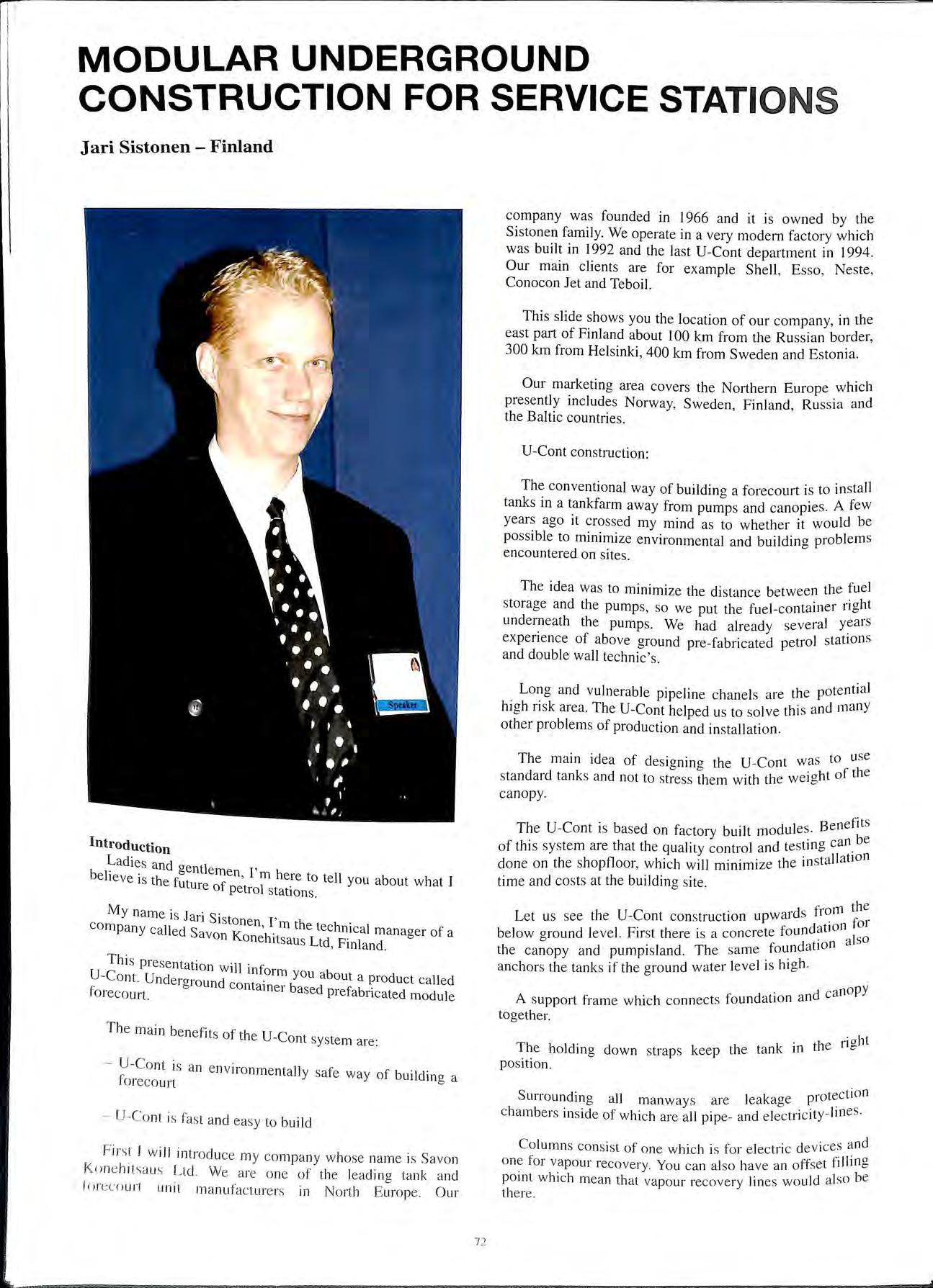
M y na me is J ari S istonen I' co mp any ca lled Sa K ' rn the technical man ager of a von oneh1tsa us Ltd , Finland
T hi s pre se nt ati o n will inf U -Co nt. Un de rgro und _orm you ab out a pro duct called fo reco urt. contarner based pre fabri cated module
T h e m ain benefits of th e U Co nt s ystem are:
U-Co nt is an en viro nm e nta ll y sa fe way of building a fo reco urt
U-C o n t is fast a nd eas y to build
F irs t I w ill introd uce my co mpa ny whose name is Savo n Ko ne hit s au s Ltd We are one of the leadin o ta nk and b fo rec ourt unit ma nu factu re rs in No rth E urope. O ur
The U-Cont is based on factory built modules. Benefbits · can e of this system are that the quality control and testmg . done on the shopfloor, which will minimize the in stallat1on time and costs at the building site.
d from the
Let us see the U-Cont con struction upwar s for below oround le vel. First there is a concrete foundation ]so b f ndat1on a the c anopy and pumpi sland. The same ou < anchors the ta nk s if the ground w ater level 1s hi g h.
. d canopy
A s upport frame which connects foundation an togeth e r.
The holding d o wn strap s keep the tank in t e "' po sition.
h riaht
S d' l l k o tection u11 o un mg a 1 manw ays are ea ag e p1 cha mb ers in si de of whi ch are all pipe- and e lec tri c ity lin es
Co lumn s co nsist of o ne whi ch is for e lect ri c de vi ces a nd o ne fo r vapour reco very. You ca n a lso have a n offset fi !lin g po int whi ch mea n th at va pour recove ry lin es wo uld a lso be t here.
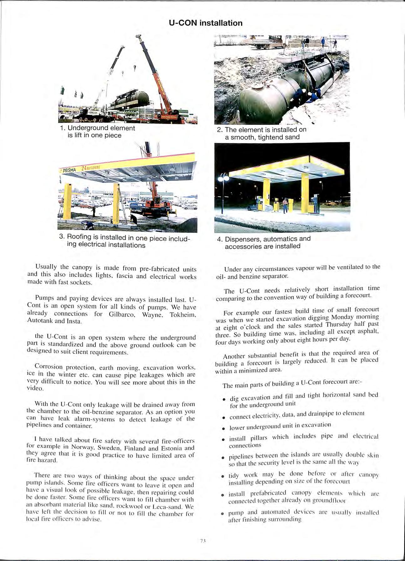
Usually the canopy is made from pre-fabricated units and this also includes lights , fascia and electrical works made with fast sockets.
Pumps and paying devices are always installed la s t. UCont is an open system for all kinds of pumps. We have already connections for Gilbarco , Wayne , Tokheim , Autotank and lnsta.
the U-Cont is an open system where the underground is standardized and the above ground outlook can be de s igned to suit client requirements.
Corrosion protection, earth moving , excavation works, ice in the winter etc can cause pipe leakages which are very difficult to notice. You will see more about this in the video.
With th e U -Co nt only leakage will be drained away from the chamber to the oil-benzine separator. As an option you ca n have leak alarm-systems to det ec t leaka ge of the pipelines and container.
_ I have talked about fire safe ty with several fire-officers for example in Norway, Sweden , Finland and Estonia and they agree that it is good practice to h ave limite d area of fir e h aza rd.
The re are tw o way s of thinking a bout the space und e r pump is la nd s Some fire officers want to leave it ope n and ha ve a v is ual look of pos s ibl e leakage , then repairing co uld be don e fa s te r. Som e fir e office rs want to fill c hamb e r with a n abso rbant m a te ri a l lik e sa nd , rockwool or Leca -s ancl. We ha ve le ft the dec is ion to fill or not to fill th e c hamb e r for loca l fir e office rs to adv ise.
Under any circumstances vapour will be ventilated to the oil- and benzine separator.
The U-Cont need s relatively short installa_tion _t ime comparing to the convention way ofbmldmg a fo1ecomt.
I . fastest build time of small forecourt For examp e ou1 . . d . · er t ·t d excavation d1aamg Mon ay mo111m"' was when we s a1 e < "'"' I If I , I ck and the sa le s started Thursday rn pas t at e1cr it o co · II t asphalt I "' So buildincr time was , includmg a excep ' t11ee. 0 h 1 e rday four days working only about eig t 10urs p < •
b t. 1 be ne fit is that the required a rea of Another su s tan ia b 1 d f ·t ·s lar cre ly red uc ed It can e p ace building a orecou1 I < "' within a minimized area.
·t f buildin cr a U-Cont forecourt are: The mam pm s o "'
· 1d fill and tiaht horizontal sand be d
• dig excavation m ' "' for the underground unit
• connect e ec 11 ' < '
I t "c i.ty data and drainpipe to element
I de l·ai·ound unit in excavation
• ower un o
• inst al l pill ar s which in c lud es pipe and e lec trical connections
• pipelin es betw ee n the is lm1d s are us uall y d o ubl e sk in 50 that th e sec unt y le vel 1s the sa me c1 !I th e way
• tidy work may be done or afte r ca nopy in s talling de pe ndin g o n s ize ol th e tore coun
• in s tall prefabricat ed canop y e le m e nt s \v hi L· h are co nn ec ted to ge th e r a lrea d y on g round floor
61 pump and a ut o ma ted .de v ices are u s uall y install e d afte r fini s hin g s urroundm g
Normal maintenance can be done without digging. It is just a matter of opening pumpisland deck. All equipment that needs maintenance is easy to reach.
So far we haven't found a lay-out which is impossible to do as a U-Cont method. Units can be installed like Lego pieces all the lay-outs you can imagine.
Here is a small forecourt without service.
And a little bit bigger lay-out for service forecourts.
It is possible to make large highway forecourts by using the same kind of elements as used with the smallest one.
Altering a forecourt is simple.
For example if a customer has a site where he expects sales to increase he can have a small one pumpisland unit.
After few years he can install another unit without closing business more than one day.
In the near future he may plan to sell more than 10 million litre of gasoline per year so he is planning to have highway model.
But unfortunately new highway will be built few kilometers away from his forecourt, so he have to alter it back to one island forecourt and move another element to nearby highway.
U-Cont forecourt is possible to recycle , if business changes forecourt changes.
In total cost comparison the U-Cont is more efficient than the traditional way.
Reasons for cost efficiency are:-
• all plans can be done in the same computer
• short installing time gives you longer business time
• you don ' t need many special groups of professionals m building
• area needed is smaller •)
This presentation covers only a small part of the U-Cont building method but as a summary the main benefits of UCont are:-
• environmentally friendly solution
• fire safety is easy to make sure
• short and easy installation
• cost efficiency comparing the traditional way of building
• easy and fast maintenance
• quality control can be done in monitored conditions at the factory
• buyer's work is easy
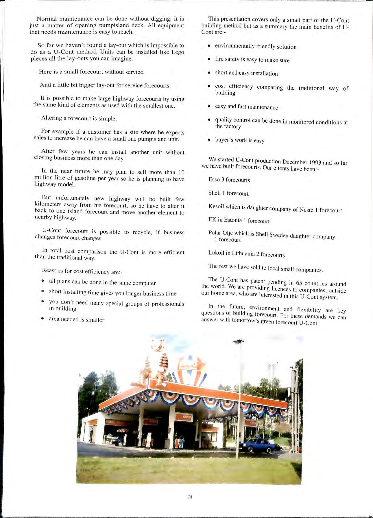
We started U-Cont production December 1993 and so far we have built forecourts. Our clients have been:-
Esso 3 forecourts
Shell 1 forecourt
Kesoil which is daughter company of Neste 1 forecourt
EK in Estonia 1 forecourt
Polar Olje which is Shell Sweden daughter company 1 forecourt
Lukoil in Lithuania 2 forecourts
The rest we have sold to local small companies
The U-Cont has patent pending in 65 countries around the world. We are provi?ing licences to companies, outside our home area , who are mterested in this U-Cont system.
In. the future,. environment and flexibility are key questions. of bmldmg forecourt. For these demands we can answer with tomorrow's green forecourt U-Cont.
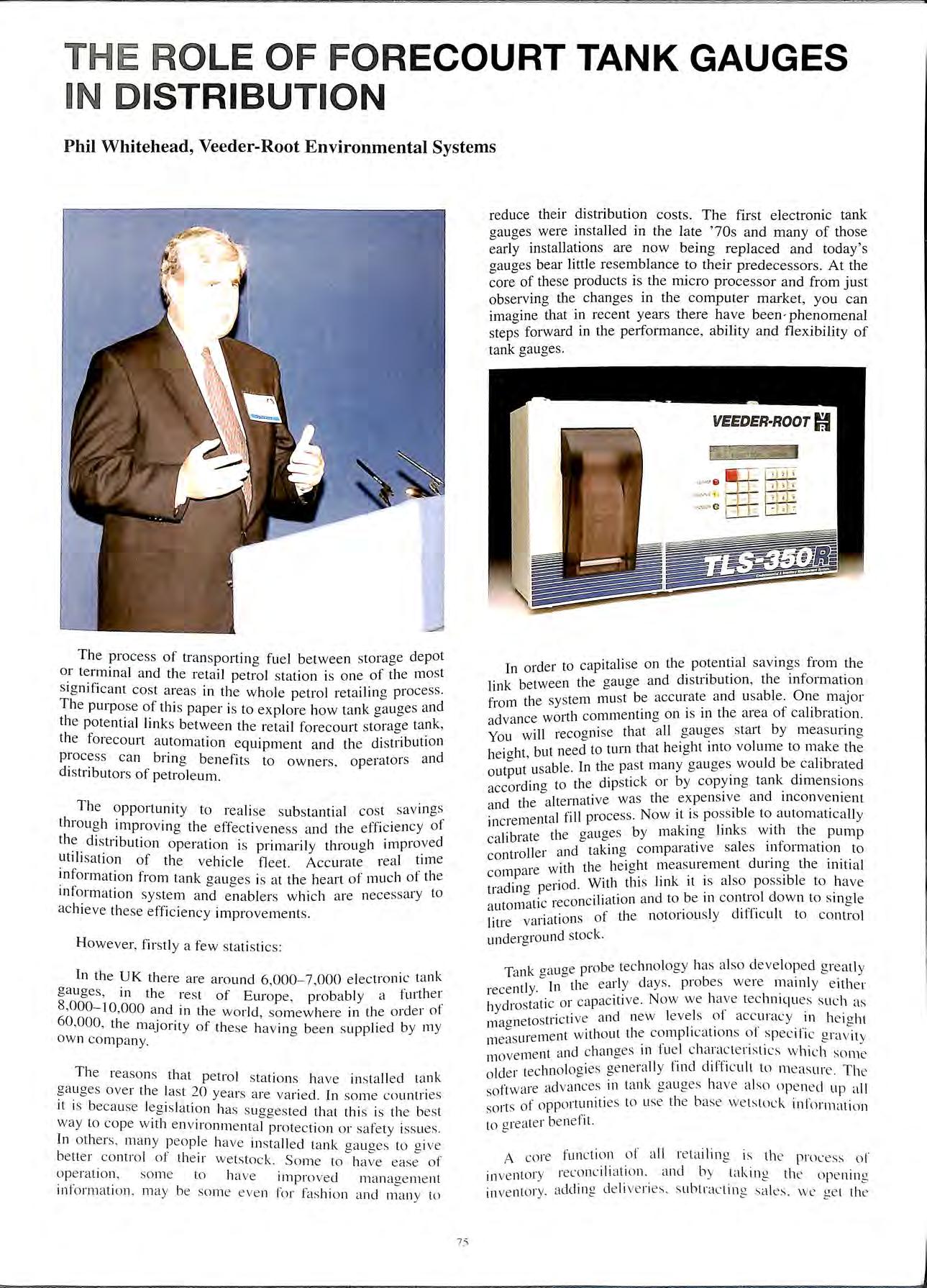
reduce their distribution costs. The first electronic tank gauges were installed in the la te ' 70s and many of tho se early installations are now being replaced and today's gauges bear little rese mbl ance to their predecessors. At the core of these products is the micro proce ssor and from just observing the changes in the computer market , you can imagine that in rece nt years there have been · phenome na l steps forward in the performanc e, ability and fl exibility of tank gauges.
The process of tran s po rtin g fu e l be tween storage depo t or termin a l and the retail petrol s ta tion is one of th e mos t sig nifi ca nt cost areas in th e w h o le pe trol retailing process. The purpo se of this p aper is to ex pl o re how tank gauges and th e potenti a l links betwe e n th e retail forecourt storage tank , the forecourt automation eq uipment and the distribution proce ss can bring benefit s to ow ne rs, operators and distributors of petroleum.
Th e o pportunit y to rea li se s ub sta ntial cost sav in gs throu g h improving the effect ive ness a nd the e ffici e ncy of th e distribution operation is prim ar il y through impro ved utili sa tion of the vehicle fl eet Accurate rea l tim e in for m at io n from tank aauaes is at th e heart of mu c h of the 0 0 mt ormat io n sys tem and e na bl e r s which are nece ssa ry to ac hi eve th ese efficiency impro ve me nt s
Howeve r, fir stl y a fe w statis ti cs:
In th e UK there a re aro und 6 ,000-7,000 e lec troni c tank ga uges, in the rest of Europe , probably a furth e 1 : 8,000- 10,000 an d in th e wor ld , so mew he re in th e o rd er of 60,000, th e majority of th ese hav in g been s uppli e d by my ow n co mp a ny.
The reaso ns th a t petrol station s have in s ta ll e d tank gauges ove r the la st 20 year s a re va ri ed In so me co untri es it is becau se leg is lati o n ha s s uggested tha t this is the be st way to co pe w ith env ironm e ntal pro tec tion o r safety iss ues. In ot he rs , ma n y people have in sta ll e d ta nk g aug es to g ive better co ntrol of th e ir we tstock. Some to have ease of operat io n, so me to have impro ve d manage me nt informat ion. may be so me e ve n for fas hi on and man y to
I ·der to capitalise o n the potential savings from the n m 1 f link between the ga uge and d1 stnbut1on , ti e m f tl sys tem mu st be acc urat e and u sabl e. One m ajor wm ie f 1·b d Wol·tli cornmentina on 1s m the a rea o ea 1 ration. a vance o Y ·11 1·ecocr ni se th at a ll ga uges start by meas unn g OU WI o · h b t need to turn that he ight mto volume to make th e he1cr t, u 0 t able In the past many ga uges would be calibrated outpu us, . k d. ·d· a to th e dip sti ck o r by copymg tan 1me ns1o ns accm lll o · cl · · d I ltern ati ve was th e expe nsiv e an mco n ve m e nt a n tie a . "bi II · t I fi.11 proces s. Now it 1s poss 1 e to a uto m at 1ca y mcre men a l b t tlie aa u aes by mak mg I mk s w ith the pump ea 1 1 a e o o 1 · f · co ntroller and taki ng co mp arati ve sa ed s o rm 1 a t1 o n to ith th e he ioht measurement unn g t 1e m1t1 a l co mp a1e w o ' bi d 110 d With thi s link 1t 1s also poss1 e to have tra lll 0 pe 0 · ·econciliation and to be m control down to s m g le a utomatic I "ff" I .· t· 011 5 of th e noto ri o us ly d1 1c u t to co ntro l litre vmia 1 und erg round stock
T k aa t1 oe probe technology ha s a lso d eve loped g rea tl y a n o' o · 1 · I Jn th e ea rl y day s. probe s were main y e ither recent Y· c • d t ti· c or ca pac 1t1 ve. Now we h <1ve tec hniqu es s uc h as hy ros a ' 0 tos tri ct ive and new levels ot accu1 ac y 1n he ig ht ma_ ne 1 1 rn e ilt wit ho ut the co mp 1cat 1o ns o · spec ifi c n ra v it \/ meas u1 e . "" ; ient a nd c hanges Ill fu e l c harac te n st 1cs wh ic h so m e move n cl I" "'" 1 o lde r technologi es ge nera ll y !111 c Il'hcu t to m eas ure. T he soft wa re adva nces in tank ga uge s have also ope ne d u p a ll ·ts of opportuniti es to us e th e b ase we ts tock in for mati o n SO I to g rea ter ben e fit.
A core fun ct io n of a ll reta ilin g is th e prncess of in ve ntor y reconcili ation and by takin g th e o pe nin g in ve ntor y. adding d e liv e rie s s ubtractin g sa les we ge 1 th e
calculated inventory effectively on hand. However if there is a negative difference between the calculated and the measured inventory, this variance is equivalent to stock loss which is in most cases equal to hard cash.
Good reconciliation is essential for distribution planning. Reconciliation variations can be created by a number of issues: temperature, evaporation, delivery shortages, calibration errors, the accuracy of the measuring device and, in some cases perhaps the most sensitive of all underground product, leaks which can be very expensive to rectify, particularly if one is looking at site clean up. It is therefore essential to identify a leak as quickly as possible and many sites use reconciliation from an interfaced tank gauge as their prime detection system.
Most people covering the subject of reconciliation draw the comparison between the control of dry stock and fuel management in petrol sites. The contrast is striking. In many cases, retailers have more control over a bag of crisps than a gallon of petrol, and with petrol continuing at the current high value, low margin position, it may be surprising that the majority of sites in Europe use the dipstick with all its inherent inaccuracies of timing, calibration, human error, damage, etc.
There are many case histories which show how the use of automatic tank gauges can improve reconciliation and save cost, and also examples where the elimination of fraud and environmental liability have been significant.
In this paper the way in which tank gauges detect leaks or the issues of calibration, or how it is undertaken are not covered in detail, but should the reader want further information, it is available by contacting Veeder-Root.
We will now move to the links which can be forged between pieces of equipment on the site and the potential benefits they give:-
1. The connection between the tank gauge and the pump controller
This in the latest systems gives synchronised real time comparison between stock and sales. It enables automatic calibration to take place and enables the site to get really good control on its reconciliation process.
2. The connection between the office, depot or wherever the centralised control point may be for a site to the gauge or POS, through modem or data link. This enables the transfer of stock data so that distribution departments can effectively interrogate the retail site and plan their deliveries to optimise the truck which is one of the single most important cost items in this whole process.
If * vehicle idle periods are kept to a minimum
* the vehicle turn round at a delivery is fast and safe
* the vehicle to site ratio is kept at a maximum
* on site inventories are kept at an optimum level with no run outs.
Truck costs are going to he reduced
(jood retailers go for an effective 100°4 fill rate with the lowesl level of inventory possible in order to reduce their 111\e-;t111e111 and working capital. The key thing is to d\ 111d run ouls and lost sales which can he directly in
conflict with reducing inventory unless you have accurate data to plan with.
Fuel forecasting algorithms are available which can predict the patterns of your usage and accurately predict when future deliveries will be required.
Using historical sales tracking, sensitised with key issues, such as holidays, sports events or other factors which may affect the local demand, can help to eliminate run outs, rush orders and haul backs and, more importantly, for the site operator to reduce the inventory investment under ground. Also by controlling the inventory better, you can avoid the common problem of over stocking on low through put lines. This often occurs when a site takes a delivery and to make up the order which has been primarily driven by a potential run out on the most popular line has required an order for less popular grades and resulted in overstocking. Here again there are some interesting case studies where using the gauge and its forecasting ability, there have been significant reductions in cash flow pressures by running the tanks at optimum levels as well as making savings in distribution costs. For the distribution centre, the ability to access this fuel forecasting information by site provides great opportunity to minimise fleet costs by managing the loading patterns and vehicle schedulino centrally, rather than being driven by individual orders.
3. 1:he third connection is between the delivery truck and site. At the moment here in the UK, and increasingly in we h?ve a number of operators making d1stnbut10n savmgs utilising the 24 hour window for driver controlled delivery. To do this in the UK you have to have a person or a specified piece of equipment on the forecourt a driver controlled delivery unit. However, 1t is now possible to make that link between the tank gauge and the delivery truck and to have your on board the truck, and Ben Martin expands on the JOlllt development that we have made in this area in the second part of the paper.
It is a fact that, in most cases, to minimise vehicle idle perio?s it is necessary to have the flexibility to deliver at any t1m_e of_ the day or night without having to consider if station is ope_n or whether or not a competent person 1s present to receive the delivery.
Our experience with DCD act1v1ty is that, for some operators, significant reductions in fleet sizes are achievable by extending the number of hours and shifts worked by each vehicle.
We have also seen benefits too in driver productivity as there is no longer the wait for site operators or the time consuming before and after dip. Some operators also argue DCDs are safer than the supervised methods, as the process is choreographed and avoids human error and failings to a great extent.
It is also worth looking at the issue of overfill prevention as it is possible to utilise the truck valves and to use the tank gauge if it is the correct type of tank gauge to trigger the overfill shutoff. It is less expensive to put your valves on the truck than to have valves on each site and this is perhaps particularly true if using mechanical valves where you may be faced with far more cost in installing a retrofit where modifying the tank tops may
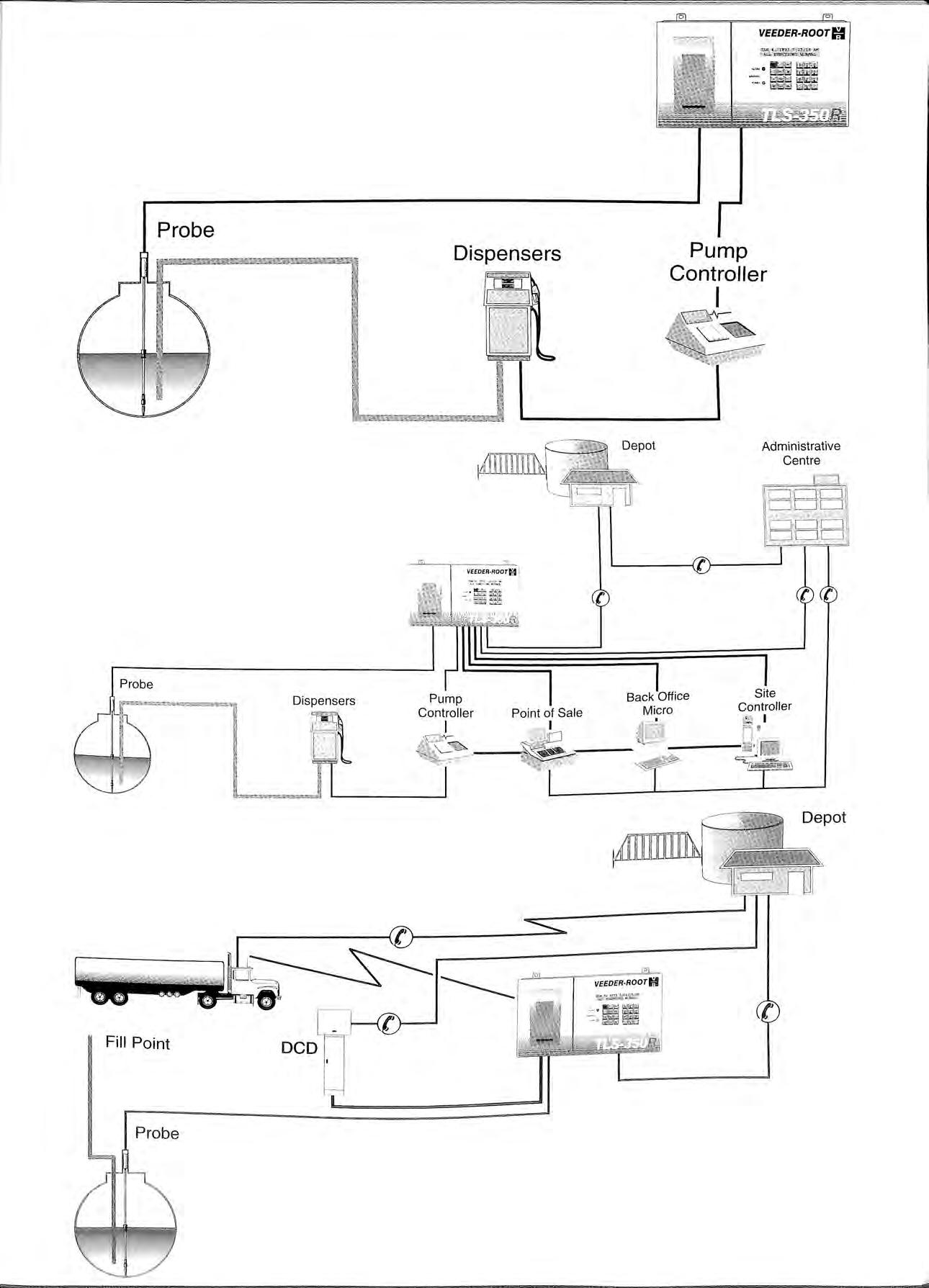
be required or other civil works than you are in the actual equipment itself
Also once you create the link between the tank gauge which has information on stock and grade and the truck, you will potentially be solving the problems of wrong grades into wrong tanks and mo.vmg towards a fully automated distribution process which can further reduce distribution costs.
Another connection that can be made to benefit is between the tank gauge and the servicing specialist. In our equipment, remote diagnostics enable this critical function now to be quickly supported by the analysis of any problems that might develop and the right remedial action being despatched , either by way of advice or an engineer correctly equipped.
As the equipment becomes more critical to the sites ability to accept deliveries and re-sell product, so the support maintenance and reliability has to be of the highest order.
The coupling of a variety of pieces of equipment together offers considerable benefits to the site operator, distribution operation and to the overall profitability of the petrol retail operation
In summary they are as follows :
* accurate stock measurement and reconciliation
* low cost accurate tank calibration
* dynamic leak detection
'" preci s ion tank te sting from the gauge
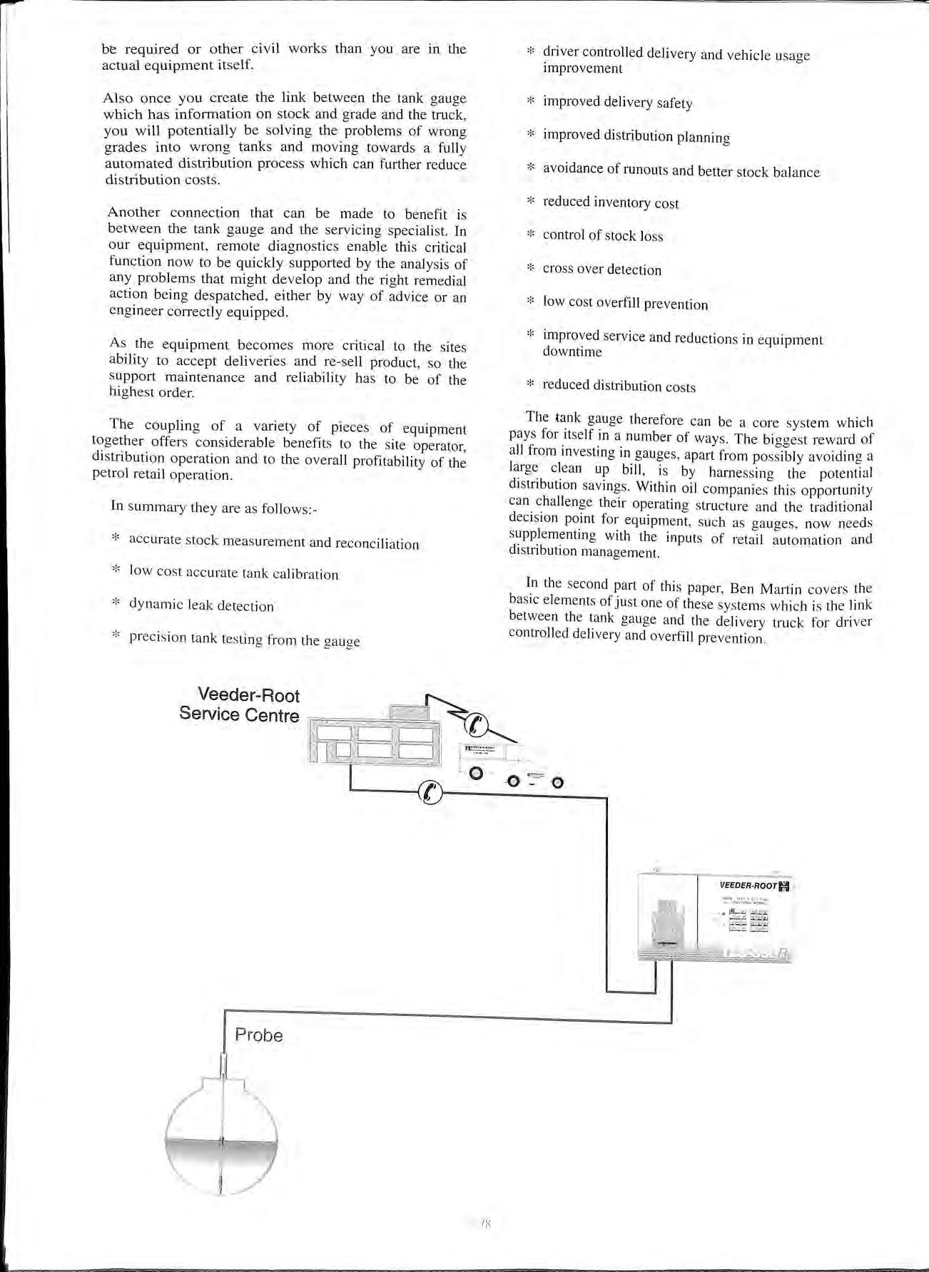
* driver controlled delivery and vehicle usage improvement
* improved delivery safety * improved distribution planning * avoidance of runouts and better stock balance * reduced inventory cost * control of stock loss * cross over detection * low cost overfill prevention * improved service and reductions in equipment downtime
* reduced distribution costs
The tank gauge therefore can be a core system which pays for itself in a number of ways. The biggest reward of all from investing in gauges, apart from possibly avoiding a large clean up bill, is by harnessing the potential distribution savings. Within oil companies this opportunity can challenge their operating structure and the traditional decision point for equipment , such as gauges , now needs supplementing with the inputs of retail automation and distribution management.
Jn the second part of this paper, Ben Martin covers the basic elements of just one of these systems which is the link between the tank gauge and the delivery truck for driver controlled delivery and overfill prevention.
Two of the key issues which face the petroleum distribution industry today are:-
* Safety in all respects including the prevention of storage tank overfill at the service station unloading of product.
* Optimisation of the use of the road tanker fleet.
Overfill prevention can be achieved in a number of ways including the use of separate mechanical shut off devices.
The optimisation of tanker fleet usage is controlled by a number of variables, one of which is the availability of service station access on a 24 hour a day, 7 day a week basis employing the Driver Controlled Delivery (DCD) procedure.
A secondary benefit of this procedure is that of improved levels of safety ranging from avoidance of the need to climb on top of the road tanker to single responsibility for the delivery of product.
It is with these two issues in mind that Drum Engineering, whose expertise is truck based, and VeederRoot Environmental Systems, whose expertise is service station based, decided to form an alliance which by benefitting from this combined expertise have been able to produce a system which brings new levels of integrity and cost effectiveness to these areas.
By virtue of the design features in the new Veeder-Root magnetostrictive storage tank measuring probe, it is possible to employ this device not only to provide contents measurement but also high level alarm outputs to trigger shutdown of product delivery.
conventional DCD Cabinet is replaced by a non intelligent cabinet which employs the basic functional requirements of site plan, keys, emergency telephone, sand etc. which are necessary to meet the regulations, hut which does not have a printer. microprocessor or keypad.
The existing design of gauge control unit housed in the kiosk has linked to it an interface unit which can receive and send information via an intrinsically safe RF link to and from the road tanker. ·
The road tanker is equipped in the cab with a Portamat on truck computer which can send and receive information to the service station kiosk via the intrinsically safe RF link.
This communication system is a separate device to the cab phone. The cab 'phone must, of course, be switched off during the delivery process.
The Portamat, in addition to managing the load, journey, unload, maintenance and fuel consumption functions also acts as the DCD intelligence and provides the facility for printing parts "A" and "B" of the petroleum certificate and confirmation of the ability of each truck compartment's volume to be safely unloaded into the designated storage tank as determined by the delivery plan.
The Portamat also has a communication link from the cab to the trailer where the Delivery Controller, again an intrinsically safe device, has the ability to open and shut the product valves leading from each trailer compartment.
The Delivery Controller also detects the presence of flow in each of the trailer compartment run off pipes.
* The Truck arrives at the service station.
* The Pmtamat makes contact with th.e station kiosk via the RF link and confirms service stat10n l.D.
* The Portamat interrogates the status of the storage tanks and obtains ullage and product grade data.
* The Portamat then activates the station lighting as necessary and tests the overfill audible alarm.
* The driver keys in to the Portamat the volume and f d t to be delivered into each storage tank. (This 0 p10 UC d" ' I t"· · c t1011 ca11 be commumcated irect Y 1om the 1111orma ' terminal).
* The Portamat then selects which trailer compartments to deliver to which storage tank
* The Portamat then prints out part ··A"" of the Petroleum Certificate on the in-cab printer.
* The driver then turns off the master switch and leaves the cab.
* The trailer Delivery Controller is then energised and allm-vs opening of the appropriate compartments.
* A communications Heartbeat"· is t'stahlished between the truck and the scr\ice station kiosk\ ia the RF link.
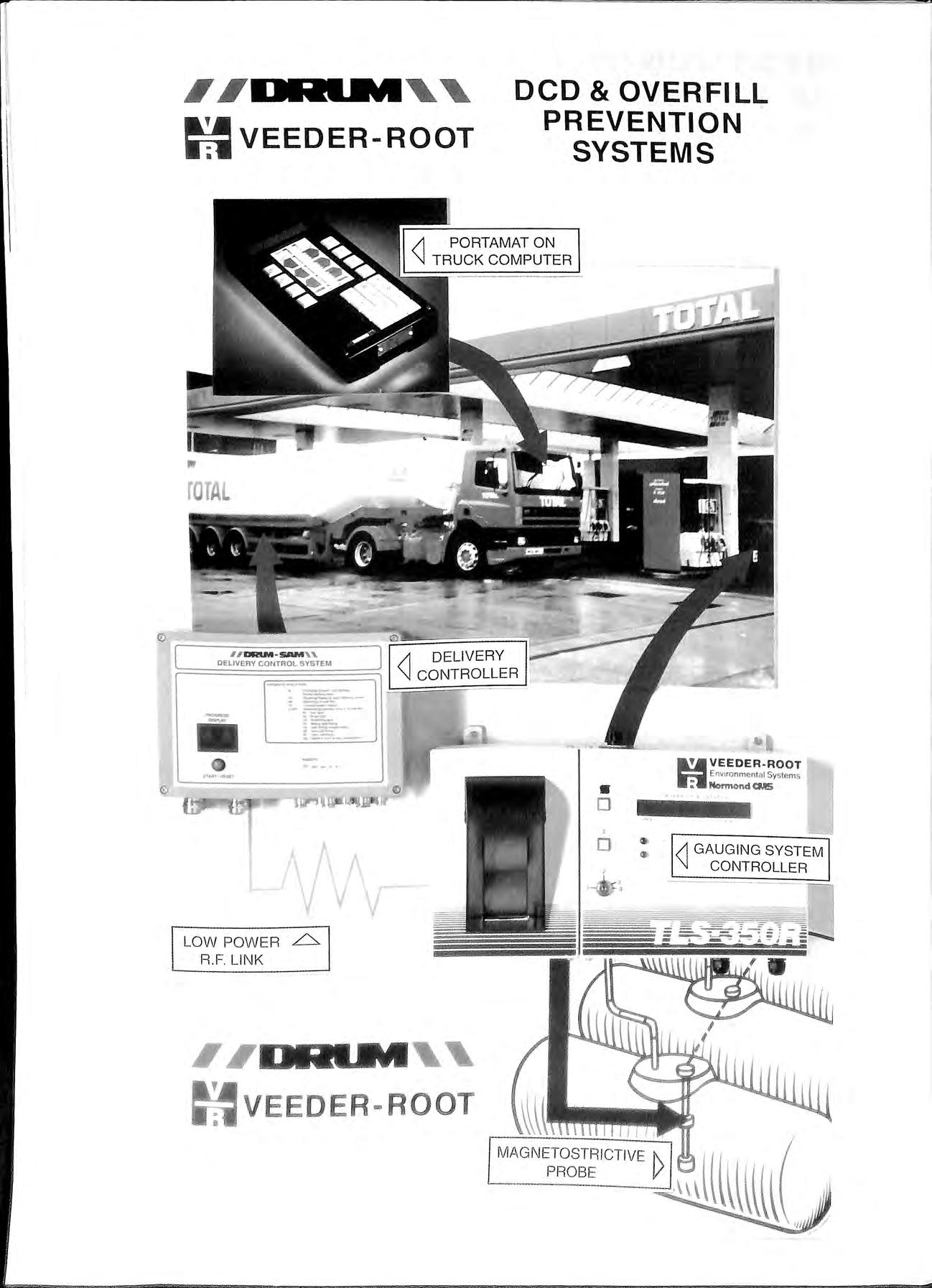
* The Delivery Controller monitors flow fro1n each compartment (up to three simultaneously) and verifies that product level change is detected in the appropriate storage tank
* If a level change is detected in the incorrect storage tank, or no level change is detected, the system shuts down.
* In the event of a storage tank level reaching the alarn1 point, the system will shut down.
* On completion of the delivery, trailer compartment valves are shut, hoses stowed, and the driver returns to his cab having turned on the master switch.
* The revised ullage report and Part "B " of the Petroleum Certificate are then produced on the in cab printer.
* Delivery Complete.
By making use of the on-truck intelligence used for other management purposes and by rationalising the functions of the latest technology in service station gauging systems with the overfill switching devices, a high integrity truckba sed system which gives intelligent environmental monitoring and control has been achieved.
In determining your future strategy for Driver Controlled Delivery and Overfill Prevention, consideration should be given to the fact that the ratio of service stations to trucks, typically of I 0: I , further means that significant capital investment and operational advantages can be gained.

On thousands of service stations right across Europe, our tank gauges are being used, 24 hours a day, to monitor underground storage tanks and Pipelines, providing critical management intorrnation and warning against leaks and losses.
At Veeder Root Environmental Systems, we are cornrn itted to providing the right solution for your s ite , through utilising innovative and proven t echnology for the measurement and control of fue l stocks and the detection of leaks .
A c ornrnitrnent which is underwritten by our u n riva lled investment in research and d eve lopment.
But having the right products is onl y part of the solution. Our commitment also extends to providing dedicated installation, servicing and technical support services .
Our specialist support teams are now backed up by a brand new control system and communications' network. All focused on satisfying you, our customers, from your initial enquiry right through to after care . Anywhere. Everytime
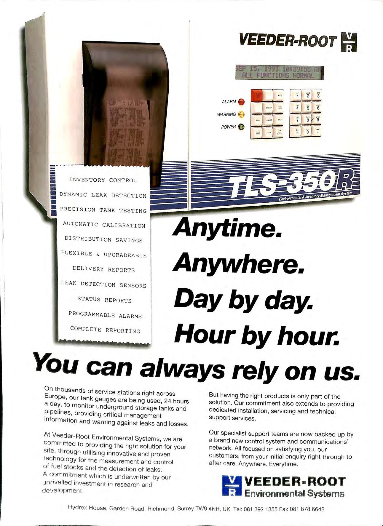


SMITH FLEX™
Flexible Dual-Wall System with Stainless Steel.
Check out the new standard in flexible underground piping the UL Listed SMITHFLEX dualwall system. SMITHFLEX piping is designed to handle all
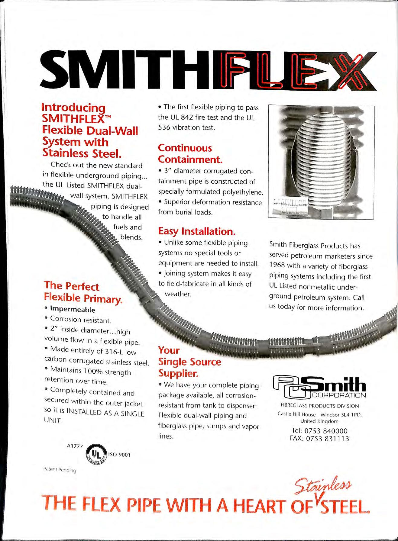
• The first flexible piping to pass the UL 842 fire test and the UL 536 vibration test.
Continuous Containment.
• 3" diameter corrugated containment pipe is constructed of specially formulated polyethylene.
• Superior deformation resistance from burial loads.
Easv Installation.
J
• Unlike some flexible piping systems no special tools or equipment are needed to install.
The Perfect F!exible Primary.
•Impermeable
• Corrosion resistant.
• 2" inside diameter high volume flow in a flexible pipe.
• Made entirely of 316-L low carbon corrugated stainless steel.
• Maintains 1 00% strength retention over time.
• Completely contained and secured within the outer jacket so it is INSTALLED AS A SINGLE UNIT. A
• joining system makes it easy to field-fabricate in all kinds of
Smith Fiberglass Products has served petroleum marketers since 1968 with a variety of fiberglass piping systems including the first UL Listed nonmetallic underground petroleum system. Call us today for more information.
Your Single Source Supplier.
• We have your complete piping package available, all corrosionresistant from tank to dispenser: Flexible dual-wall piping and fiberglass pipe, sumps and vapor lines
0753 840000
0 75 3 8 3111 3
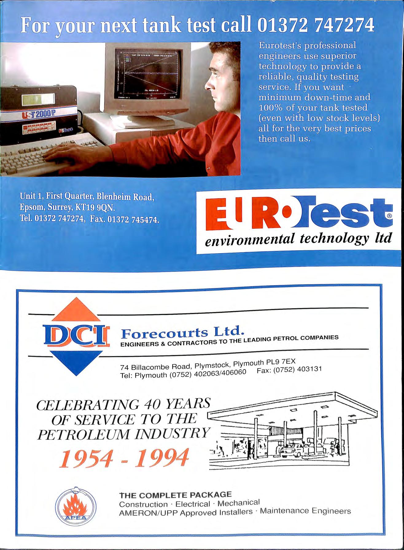
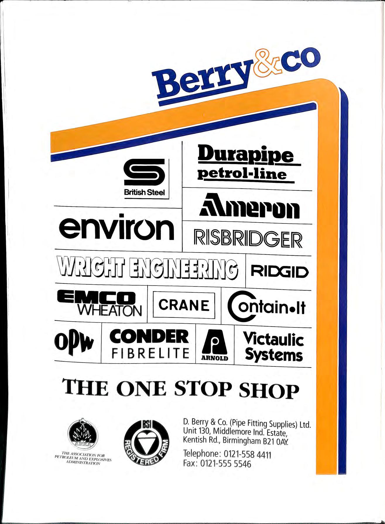
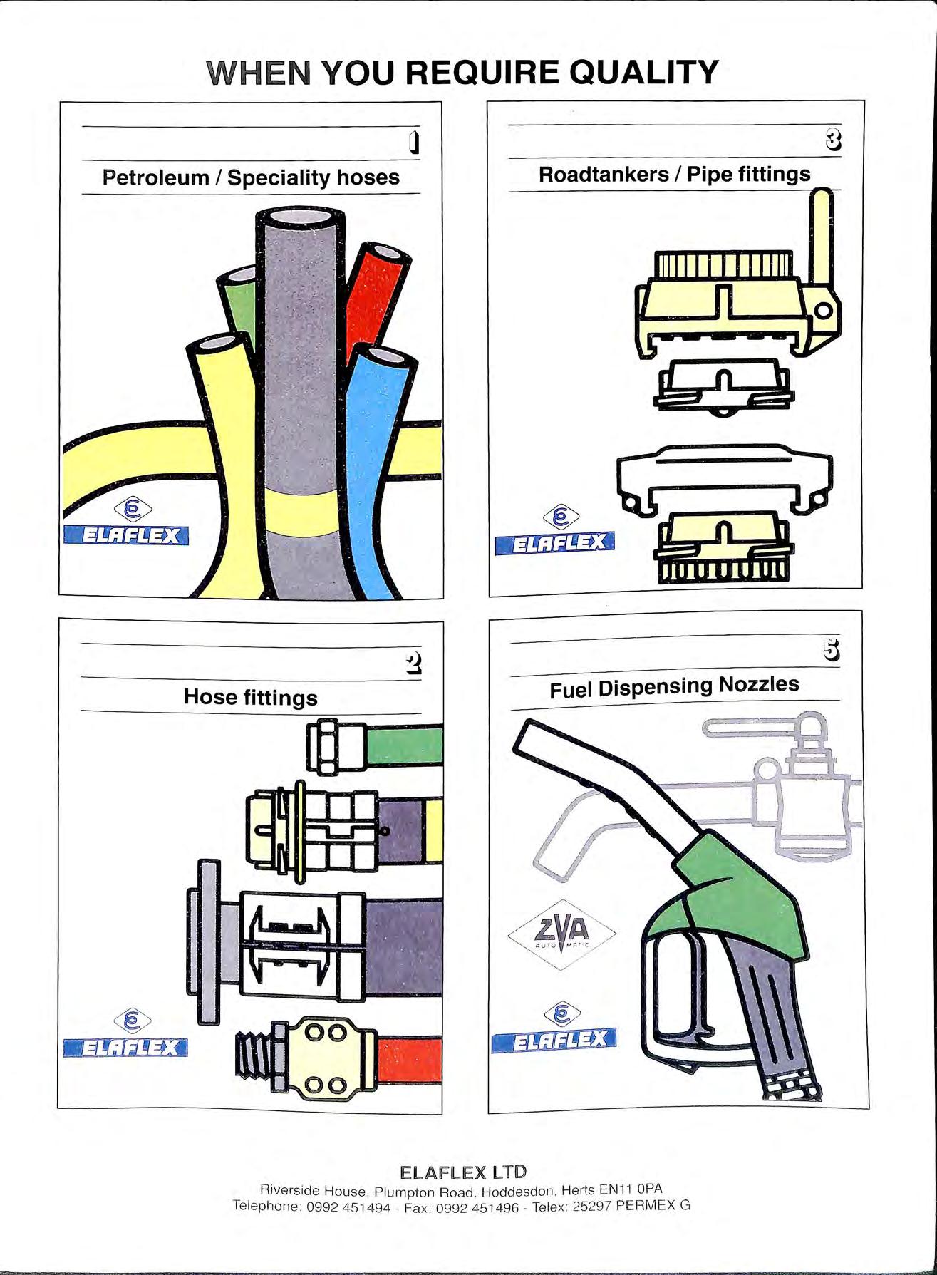
Ltd. , Maitland Road , Lion Barn Business Park , Needham Market, Ipswich , Suffolk, IP6 SNZ. Tel : 01449 722822. Fax : 01449 721821.