;.: · _ < -"::": "' -. ,.....,._ { _.··· __ The • Journal of the Association for Petroleum and Explosives Administration · , • 40th Anniversary 1958-1998 • 40th Anniversary I !);)8 I !)!)8 40rH ANNIVERSARY CONFERENCE ISSUE VOLUME 36 No. 4
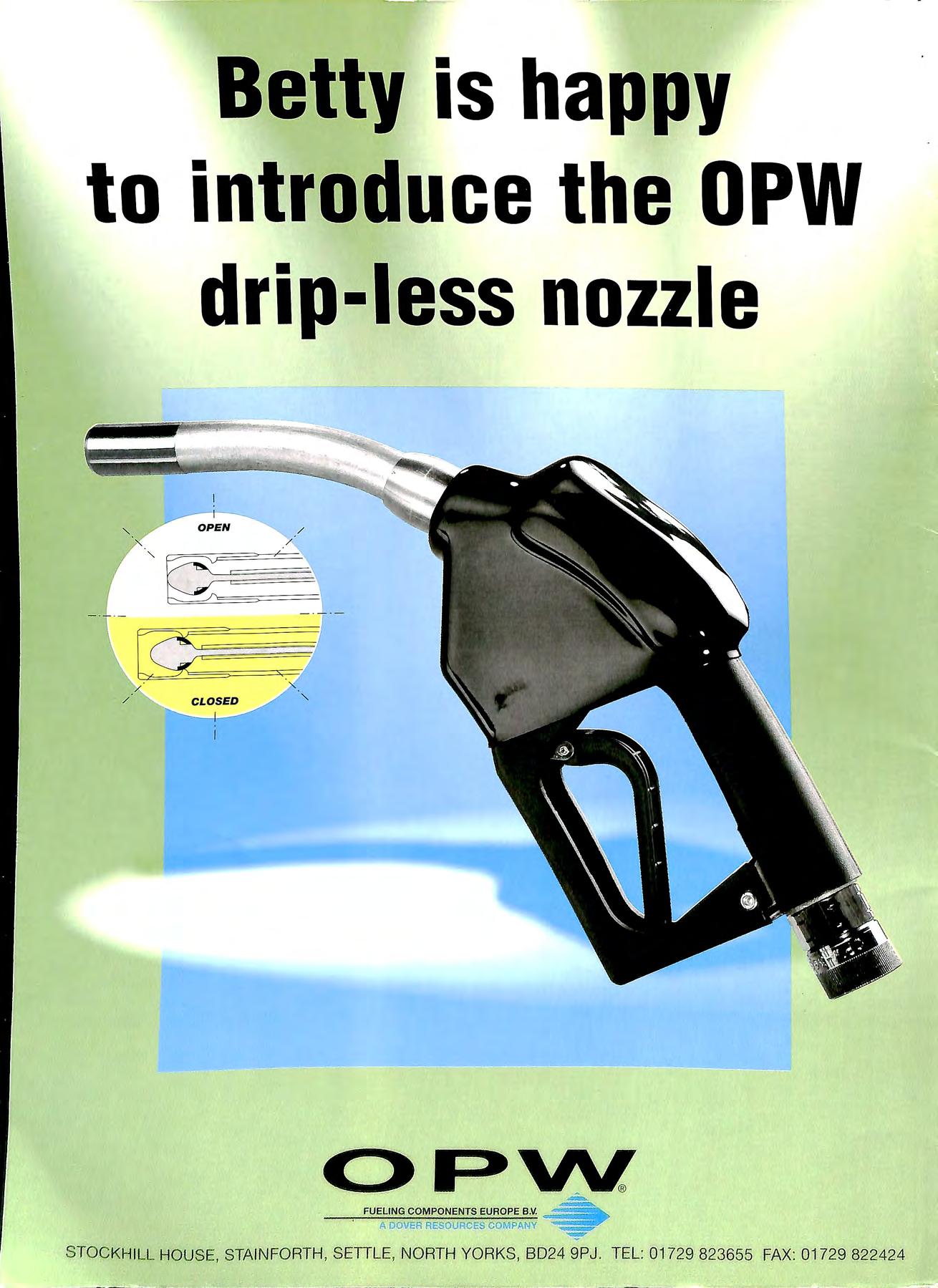
Betty is happy to introduce the OPW drip-less nozzle I O PEN / / _-: FUELING COMPONENTS EUROPE B 11. A DOVER RESOURCES COMPANY STOCKhllll HOUSE, STAIN FORTH , SETTLE , NORTH YORKS , 8024 9PJ. TEL: 01729 823655 FAX: 01729 822424
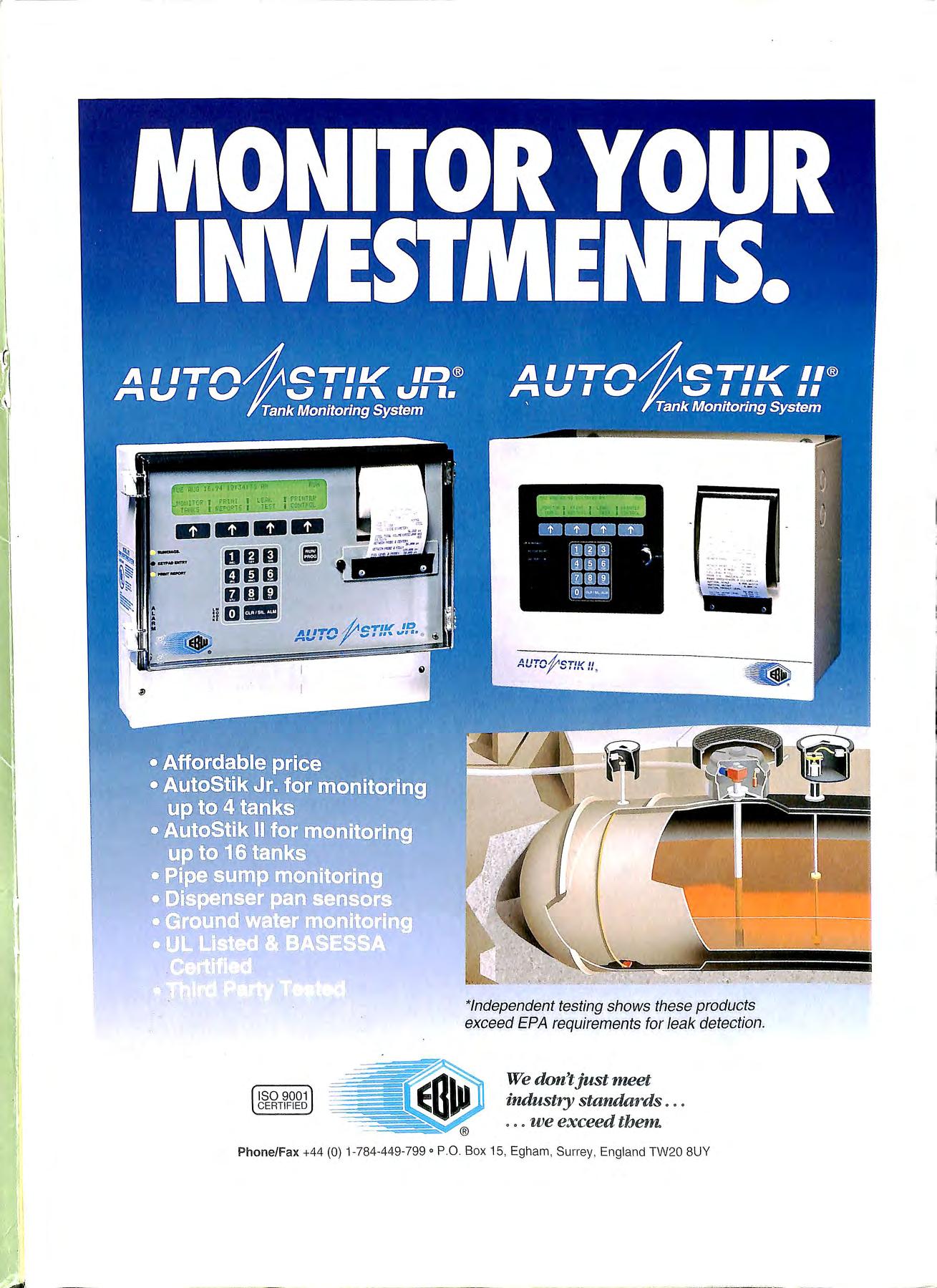
' I I \ \ I ! ISO 9001 CERTIFIED 11 "' ·-7 ,11 *Independent testing shows these products exceed EPA requirements fo r le a k detection . We don't just meet industry standards . .. ... we exceed tbe1n Ph o ne/Fax +44 (0) 1-784-449-799 ° P 0 Box 15, Egham, Surrey , England TW20 8UY
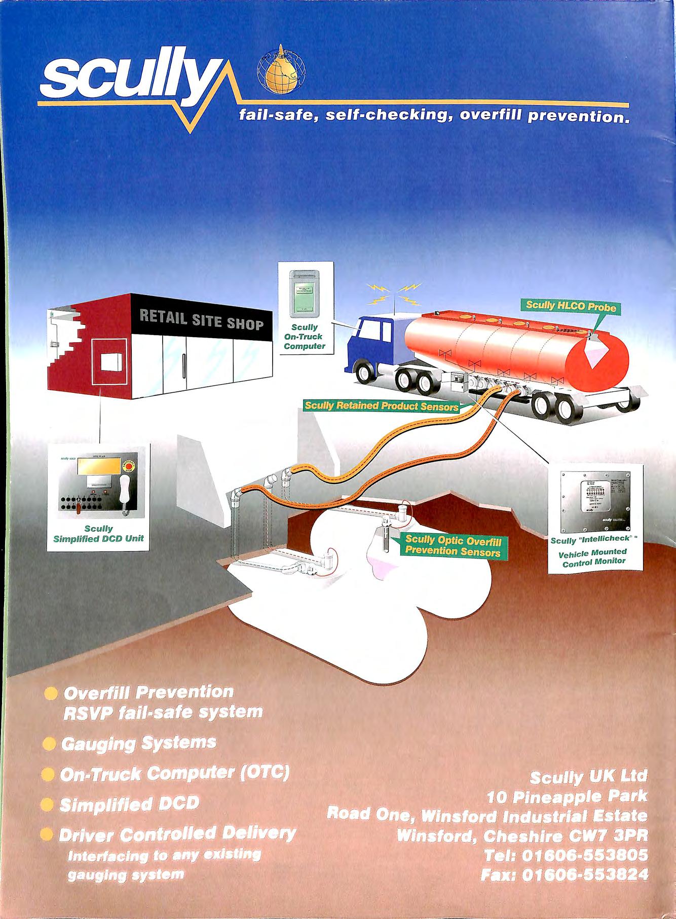 Scully On-Truck Computer
1 Scully " lnte/licheck" " Vehicle Mounted Control Monitor
Scully On-Truck Computer
1 Scully " lnte/licheck" " Vehicle Mounted Control Monitor
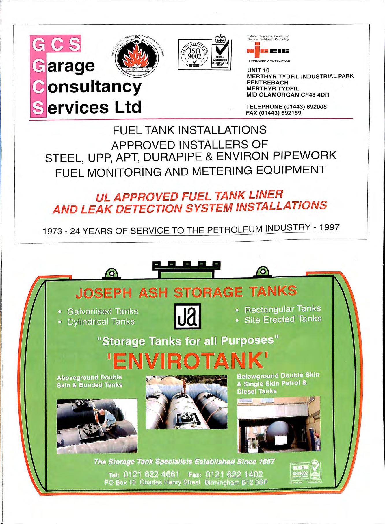
a rage onsultancy ervices Ltd Nationa Inspection Council !or Electncal lnslallalion Contracting • •le E•C APPROVED CONTRACTOR UNIT 10 MERTHYR TYDFIL INDUSTRIAL PARK PENTREBACH . MERTHYR TYDFIL MID GLAMORGAN CF48 4DR TELEPHONE (01443) 692008 FAX (01443) 692159 FUEL TANK INSTALLATIONS APPROVED INSTALLERS OF STEEL, UPP, APT, DURAPIPE & ENVIRON PIPEWORK FUEL MONITORING AND METERING EQUIPMENT UL APPROVED FUEL TANK LINER AND LEAK DETECTION SYSTEM INSTALLATIONS 1973 24 YEARS OF SERVICE TO THE PETROLEUM INDUSTRY - 1997 Q 0

• Tank cleaning • Gas free certification • Safe excavation and removal of petrol tanks • In situ tank decommissioning • Foamed concrete filling • Hydrophobic foam neutralisation • Mobile oil/water separator for low cost interceptor drainage • Supply of rotationally moulded or GRP interceptors • Emergency oil spill response contractors • Land remediation OTS are Licensed Waste Carriers and operate our own Licensed Petrol Tank Disposal Site No : SY-40 W e are a Quality Assured Company to BS/ EN/I SO 9002 He ad O ffic e 013 86 8 5 3409 Fax 013 86 858 9 28 Brist ol 0 1179 30454 5 Derby 01332 385892 Newport 0 163 3 250003 Po rtsmouth 0 1705 381066 Reading 01189 505556 OT . s Ltd, H ead Offi ce, Spr inghill Industrial Estate,Springhill, Mor eton in Marsh, • (;Joucestershire, ( ; L 56 9TP

High integrity pipework systems for forecourt installations Distributed by PURFLEET FORECOURT SERVICES Tel: 01708 863931 Ext. 219 Fax: 01708 864 140 l!etrol·line Rius Durapipe S&LP • No 1 UK manufacturer of polyethylene pipes • Superior elect rofusion jointing system • High flow rates • Available in four sizes for suction and pressure system s • Competitive prices • Nationwide delivery e-m ail: purfleet fo recourt services@ harris group cq u k PURFLEET FORECOURT SERVICES LTD 520 London Road, West Thurrock, Grays, Essex RM20 3BE LEDBURY WELDING & ENGINEERING LTD. NETHERWOOD ROAD, ROTHERWAS INDUSTRIAL ESTATE, HEREFORD HR2 6JU (TEL: 01432-275566) (FAX: 01432-358493) A COMPLETE RANGE OF ABOVE & BELOW GROUND STORAGE VESSE LS QU AUTY UNDERGRO UN D TANKS DOUBLE AND SINGLE SKIN QUALITY UNDERGROUND TANKS SPEC IA U ST COATING LEAK DETECTION - OVERFILL PREVENTION DEVICES MANWAY ACCESS FRAMES MULTIPLE COMPARTM ENTS ABOVE GROUND9 FUllY BLIND ED TOTALLY ENC LOSE 6 0 ERV PA C KS 9 600 GAllON TO 20 9 000 A O N
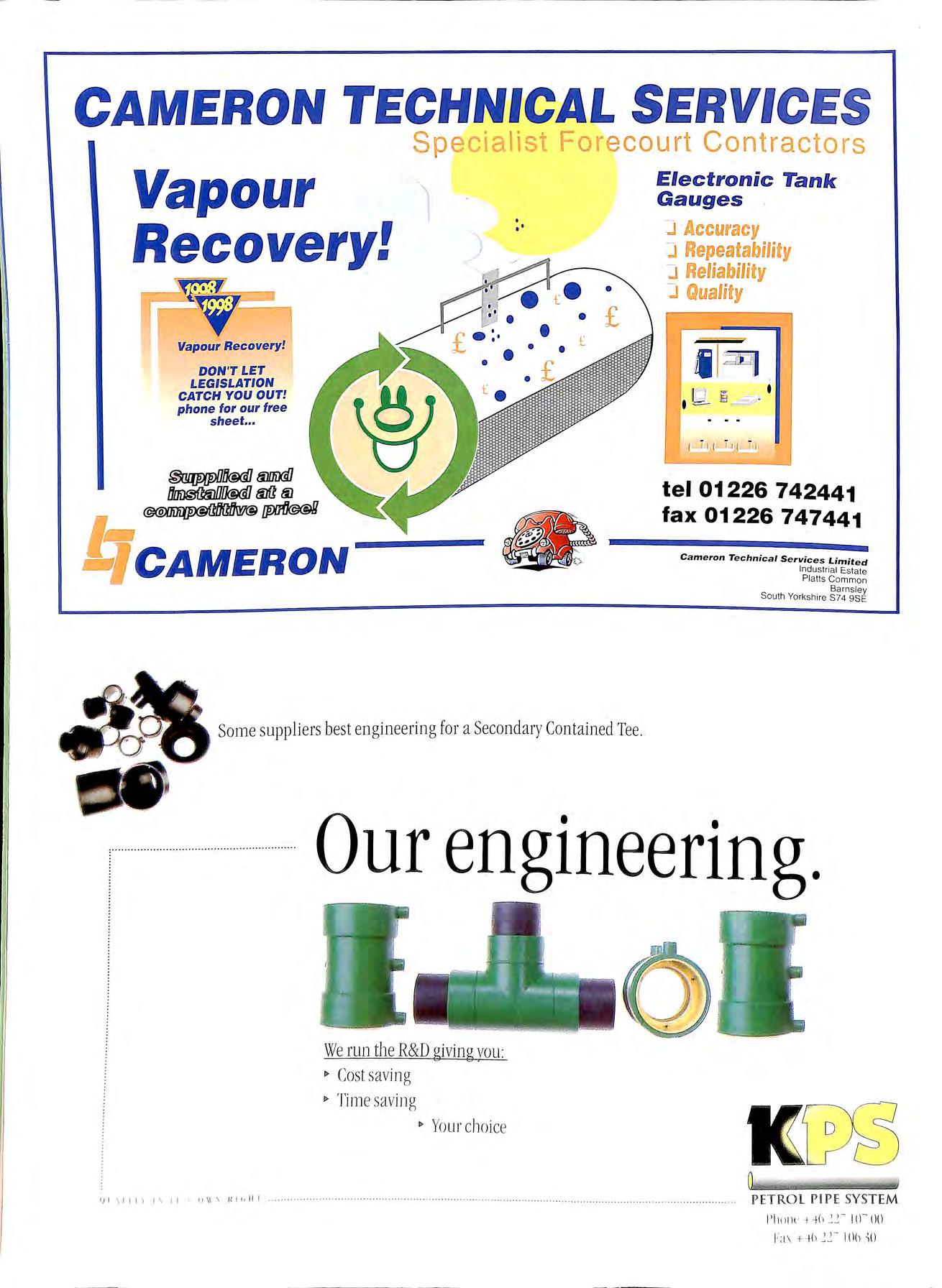
CAMERON TECHNICAL SERVIC ES Sp : court Contractors Vapour Recovery! __v Vapour Recovery! DON 'T LET LEGISLATION CATCH YOU OUT! phone for our free sheet•.• ti1 !;;CAMERON J . •' • £ Some suppli ers bes t engineering for a Secondary Contained Tee. Electronic Tank Gauges J Accuracy J Repeatability J Reliability J Quality · 'tel 01226 742441 fax 01226 747441 Cameron Technical Services Limited Industrial Estate Platts Common Barnsley South Yorkshire S74 9SE Our engineering. We run the R&D givin g vo u: I> Cost sav ing I> Tim e saving I> Yo ur choice I) I \ I I ! J \ I J II \\ \ II J ! I! I ······· ·······• ·· PETROL PI PE SYS TEM 1'1 111111· H h 10- ()() 1:a.\ + 1h IOb -\0

CPINSTALLATIONS LTD. (Established 1968) Unit 2; ·275 Prince Avenue, Westcliffe on Sea, Essex SSO 0 JP. Tel: 01702 392110 (24hrs ans) Fax: 01702 392126 WASTE MANAGEMENT NATIONWIDE FORECOURT DRAINAGE & INTERCEPTOR SERVICE Cleaning & emptying of interceptors and associated drainage system s found on garage forecourts • Interceptors • Catc h Pits • Tank To ps • Gullies • Car/Jet Wash Pits • BucketTraps • Surface Drain age • Bel ow Surface Channels Drainlines Water tran spo rted for ta nk testin g plus tre atme nt & disposal of th e co ntam inated water. EVESHAM (CH 386) 47190 INDUSTRIAL & TAN1K CL&:ANING Petro l, oil & so lvent tanks c leaned to OCT EL and Petro leum Industry spec ificat ions. fil GlOUCESTER 452) 507432 Head Office : Grange Road Botley Southampton 8030 2GD Tel (01489) 782232/6 Fax (01489) 78982 1 GROUP lTD SPECIALISTS IN PETROL PUMP AND PIPEWORK INSTALLATIONS. APPROVED INSTALLERS OF: AMERON AND SMITHS GRP. DURAPIPE AND UPP. ENVIROFLEX AND ENVIRON. PRECISION TANK AND LINE TESTING EMERGENCY REPAIR SERVICE. 2 BERCTA ROAD, NEW ELTHAM LONDON SE9 3TZ TEL : 0181 850 2211 FAX: 0181 -8 50 5599 D DC BUILDERS LTD FOR SERVICE QUALITY & RELIABILITY WE OFFER A COMPLETE SERVICE ON MAINTENANCE AND IMPROVEMENT WORKS TO THE PETROLEUM RETAIL MARKET D D C BUILDERS LTD i ST CLAIR CLOSE CLAYHALL ILFORD ESSEX XG5 OPA Te]: Oli8[ 0 55 0 52 16 Fax : 0 li 81°55 1Ql 6095
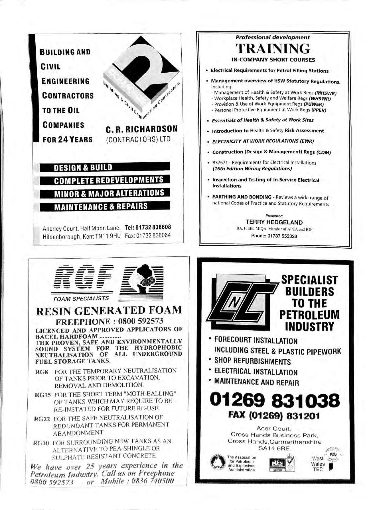
BUILDING AND CIVIL ENGINEERING CONTRACTORS TO THE OIL COMPANIES FOR 24 YEARS C.R. RICHARDSON (CONTRACTORS) LTD DESIGN & BUILD COMPLETE REDEVELOPMENTS MINOR & MAJOR ALTERATIONS MAINTENANCE & REPAIRS Anerley Court, Half Moon Lane , Tel: 01732 838608 Hildenborough , Kent TN11 9HU Fax: 01732 838064 -------_. .j.. _ _. ·t'·'f" ::: -==--li== -------- -----..-----.__......_FOAM SPECIALISTS RESIN GENERA TED FOAM FREEPHONE : 0800 592573 LICENCED AND APPROVED APPLICATORS OF BACEL HARDFOAM ....... .. THE PROVEN, SAFE AND ENVIRONMENTALLY SOUND SYSTEM FOR THE HYDROPHOBIC NEUTRALISATION OF ALL UNDERGROUND FUEL STORAGE TANKS. RG8 FOR TIIE TEMPORARY NEUTRAL IS ATION OF TANK S PRIOR TO EXCAVATION, REMOVAL AND DEMOLITION RG15 FOR T HE SHORT TERM "MOTH-BALLING" OFTANKS WHICH MAY REQUIRE TO BE RE INST A TED FOR FUTURE RE USE. RG22 FOR THE SAFE NEUTRALISATIO N OF REDUNDANT TANKS FOR PERMANENT ABANDONMENT RGJO FOR S URROUNDING NEW TANK S AS AN ALTERNATIVE TO PEA-SHINGLE OR SU LPHATE RE S IST ANT CON C RETE. We ha ve over 25 years experience in the Petroleum Indu s try. Cal! us on Freephone 0800 5 92573 mr Mobile : 0836 740500 -·-------Professional development TRAINING IN-COMPANY SHORT COURSES • Electrical Requirements for Petrol Filling Stations • Management overview of HSW Statutory Regulations including: ' Management of Health & Safety at Work Regs (MHSWR) Workplace Health, Safety and Welfare Regs (WHSWR) Provision & Use of Work Equipment Regs (PUWER) Personal Protective Equipment at Work Regs (PPER) • Essentials of Health & Safety at Work Sites • Introduction to Health & Safety Risk Assessment • ELECTRICITY AT WORK REGULATIONS (EWR) • Construction (Design & Management) Regs (CDM) • 857671 Requirements for Electrical Installations (16th Edition Wiring Regulations) • Inspection and Testing of In-Service Electrical Installations • EARTHING AND BONDING Reviews a wide range of national Codes of Practice and Statutory Requirements Presenter. TERRY HEDGELAND BA. FIEIE. MIQA. Member of APEA and IOP Phone: 01737 553328 SPECIALIST BUILDERS TO THE PETROLEUM INDUSTRY • FORECOURT INSTALLATION INCLUDING STEEL & PLASTIC PIPEWORK • SHOP REFURBISHMENTS • ELECTRICAL INSTALLATION • MAINTENANCE AND REPAIR 01269 831038 FAX (01269) 831201 Acer Court , Cross Hands Business Park , Cross Hands ,Carmarthenshire The Association for Petroleum and Explosives Administration SA14 6RE 1•1 fu(:;. J.! West .,;1,.;,;"" Wales if' TEC "

A. J. Bayliss (Stourport) Ltd Petroleum Engineers Petrol, Fuel Oil and Electrical Installations 11/12 HODFAR ROAD, SANDY LANE INDUSTRIAL ESTATE STOURPORT-ON-SEVERN DY13 9QB TELEPHONE: 01299 824541-2-3 FAX: 01299 827638 ' SPECIALISING IN ALL ASPECTS OF FORECOURT PETROLEUM INSTALLATIONS, SERVICING AND PRECISION TANK TESTING FULLY ACCREDITED TO 85 EN 150 9002: 1994 Care For The Environment... Make For ecourts A Safer Pl ace To Wo rk And Visit... Pr ovide Quality Solu tio n s To Forecourt Engineering Pr oblem s .. . rR SBrRllDGlErR VAPOUR RECOVERY PRESSURE VACUUM VALVES VAPOUR LOSS REDUCTION SYSTEMS UNDER PUMP/CHECK VALVES DESIGN & DEVELOPMENT INSITE UNE TESTING rus-STOP OVERFi llL PREVENTION DJEVlICE rusBruDGER lTD . Stychen.s lLane, Suurrey RHl 4lN Td : ( +44 01883 7 4 3107 Fax: ( +44 01883 744342
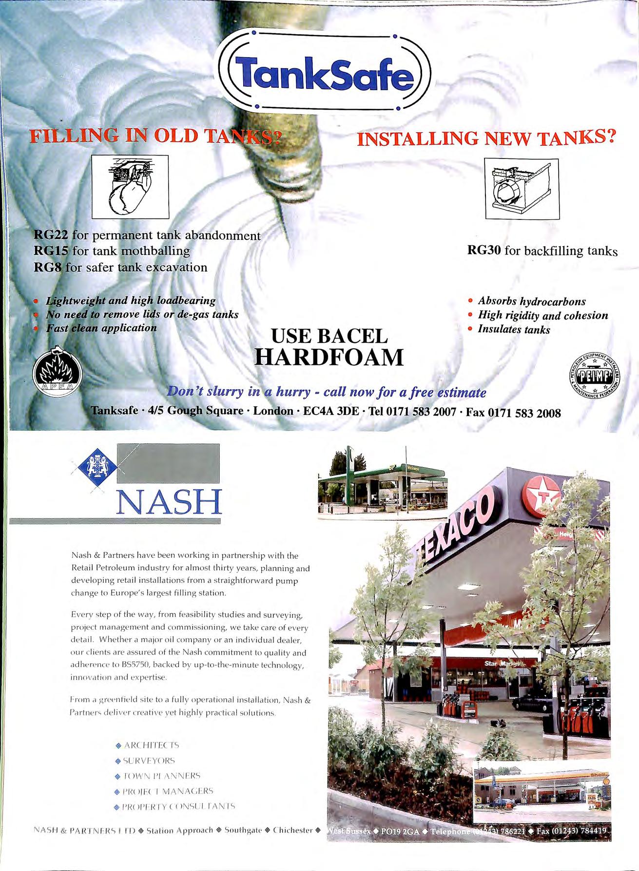
1· I FILLING IN OLD INSTALLING NEW TANKS? USEBACEL HARDFOAM RG30 for back.filling tanks • Absorbs hydrocarbons • High rigidity and cohesion • Insulates tanks 'l)on 't slurry in a hurry - call now for a free estimate ksafe · 4/5 G'1Qgh Square· Lond(i)n · EC4A 3DE ·Tel 0171583 2007 ·Fax 0171583 2008 NASH Nas h & Par tn e rs ha ve bee n wo rkin g in partne rs hi p w ith th e Re ta il Pe tro le um indu s try for a lm o s t t hi r ty ye ars, p la nning a nd d eve lopi n g reta il in s ta lla ti o n s fro m a s tr a ig htfor wa rd pump c h a n ge to Europe' s la rges t fillin g s tat io n Ev e ry s te p o f th e way, fro m fe as ibi li ty s tud ies a n d s u r vey in g , proj ec t mana ge m e nt and co mm iss io nin g, we take ca re of eve ry d e ta il W h e ther a m a jo r o il co mp a n y o r a n indi v idua l d ea le r, o ur c li e nts a re a ss ur ed o f t h e Nas h co mm itm e nt to qua li ty a nd ad h e re nce to BS5750, backe d b y up to- th e -m in ute tech n o logy, in n o vat ion a nd ex p e rti se. From a g ree nfi e ld s ite to a fu ll y op e rat io n a l in s ta ll at io n , Nas h & Partn e r' de li ve r cr ea ti ve ye t hi g hl y pra c ti ca l so lu t ion s. • SURVFY( )J\ :, • 1O W N l'I ;\ N l\JF. I<'-> • !' !« l/Et I J' l(O l' f I<JY C< >N SLI rA N I c., N AS H & PARTN r HC., I TD + S ta tion S ou t h g at l.' + C hi ch es te r +
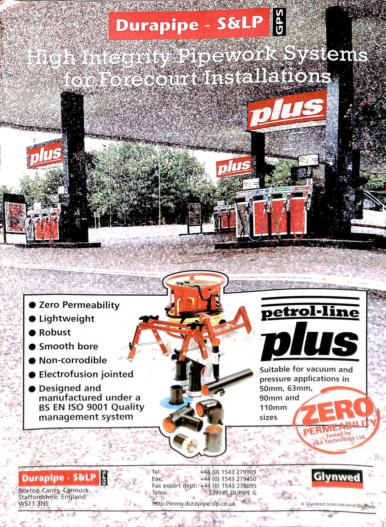
:. 'f...;. • Zero Permeability • Lightweight •Robust • Non-corrodible • Electrofusion jointed • Designed and manufactured under a BS EN ISO 9001 Quality management system Fax exl'Jo rt dept: Telex: (O) 1543 279909 +44 (O) 1543 279A 50 .44 (O) 1543 278095 DUelPE G f'ftitp :I /wwl\V.du rap ipe sIp. co .u k eetrol·line 11.lus Suitable for vacuum and pressure applications m SOmm, 63mm, 90mmand ,L110mm sizes A Glynwe cl Inte r nati o na l b • , ' U:i.;. ess
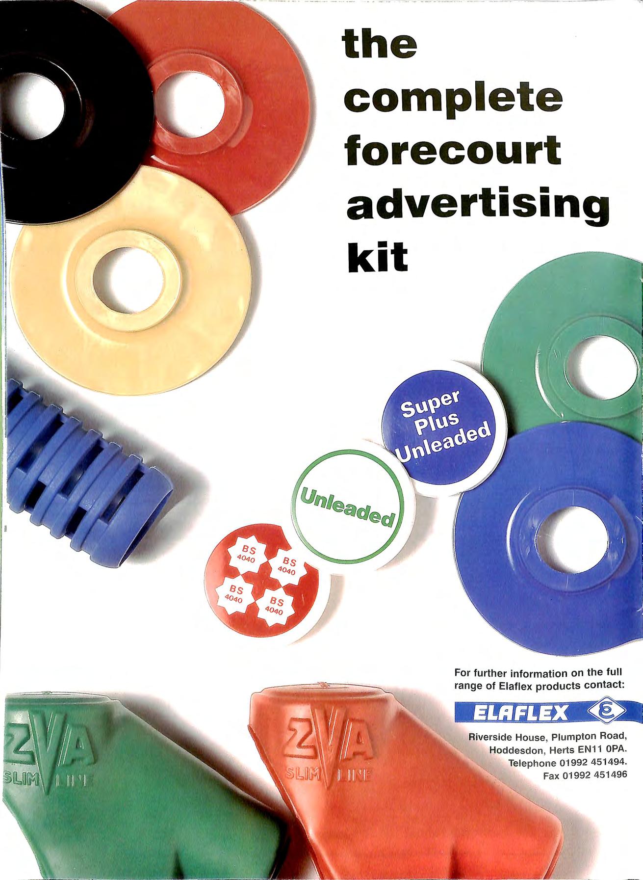
the complete forecourt advertising kit For further information on the full range of Elaflex products contact: Riverside House , Plumpton Road, Hoddesdon , Herts EN11 OPA. Teleph one 01992 451494. Fax 01992 451496

DAVID PLUMB & CO LTD 169 Frenches Road, Redhill RH1 2HZ Telephone: 01737 767524 Service to the Petroleum Industry Since 1966 Member A.P.E A. The safe alternative to water-filling of petrol tanks for certain applications Using our oil/water separator, we can dispose of water from petrol tanks at a fraction of the cost of tanker hire Work undertaken by fully trained and medically certificated personnel Hot and cold cutting, removal and documented disposal of redundant oil and petrol tanks. Product uplift and transfer • Converting double=compartment tanks to Solid filling of redundant tanks • Coid cutting open and cHsposing of tanks Excavation • Tank removal • Contaminated and reinstatement

DRIP diesel nozzle
Situation Today
the area around a diesel dispenser is contaminated by diesel which has fallen onto the forecourt for one reason or the other. One of the main reasons is that motorists do not wait that extra second for the nozzle to drain before removing the spout from the car filler pipe
The Solution
The 'ZVA Slimline nozzle is now available with the New Drip Stop spout ER242. 1TMV. The patented magnetic closure inside the spout works after refuelling has finished. The Drip Stop operates in two ways Firstly it closes to prevent diesel dripping when the spout is removed from filler pipe too quickly and secondly, it retains the remains left in the spout so that the next customer doesn 't spill this diesel onto the forecourt when removing the nozzle from the dispenser.
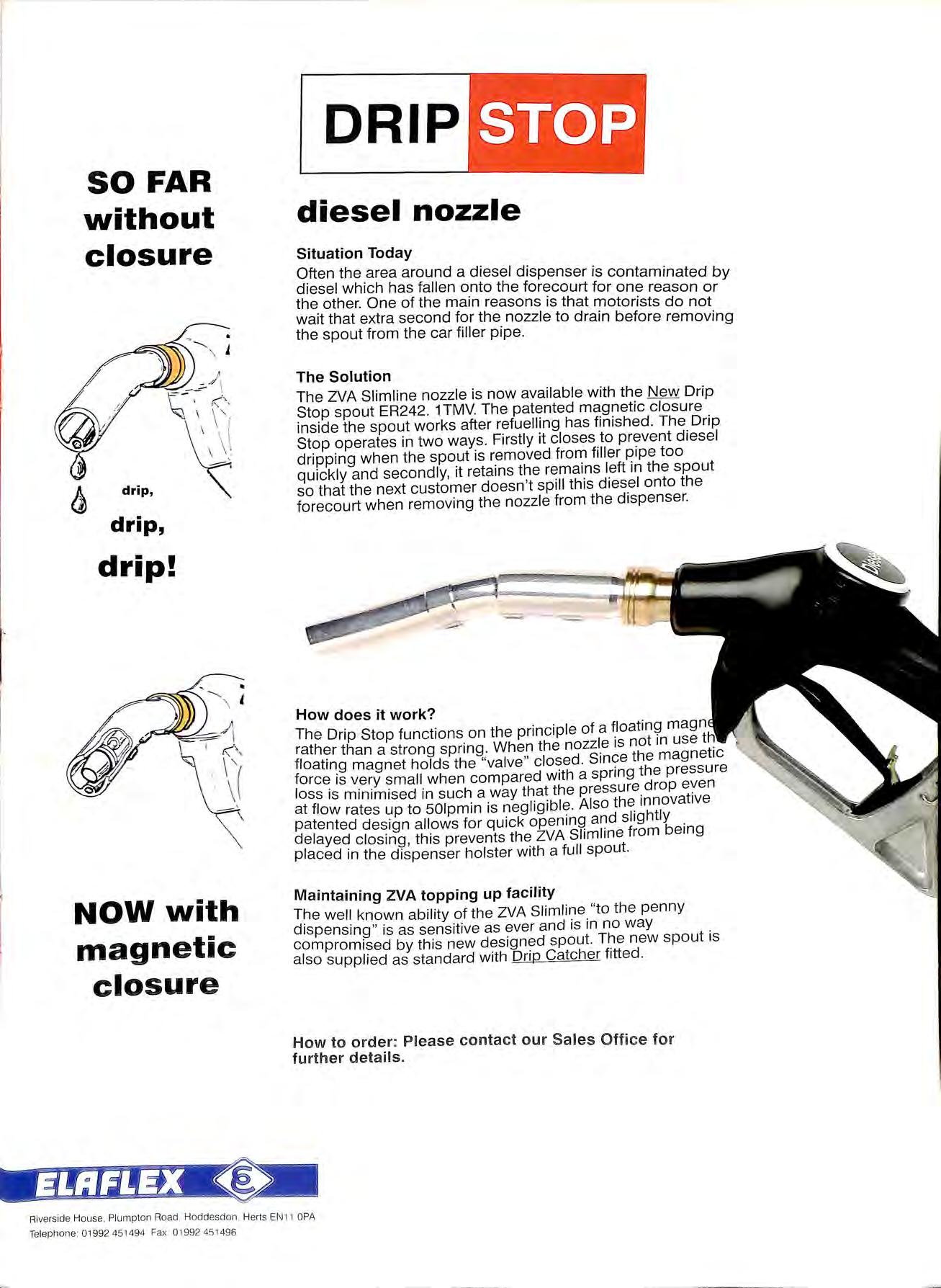
How does it work?
The Drip Stop functions on the principle of a magn rather than a strong spring . When the nozzle 1s not in use floating magnet holds the "valve " closed Sinc;;e the magnetic force is very small when compared with a spring the pressure loss is minimised in such a way that the pressure drop at flow rates up to 501pmin is negligible. Also the_1nnovat1ve patented design allows for quick opening and slightly . delayed closing, this prevents the ZVA Slimline from being placed in the dispenser holster with a full spout.
Maintaining ZVA topping up facility well known ability of the ZVA Slimline_ "to the penny dispensing " is as sensitive as ever and 1s in no way . compromised by this new designed spout. new spout 1s also supplied as standard with Drip Catcher fitted
Ho w t o order : Please contact our Sales O ffice for further details.
SO FAR without closure \ I \ drip, drip, drip! ' NOW with magnetic closure \
Riverside House, Plumpton Road Hoddesdon Herts EN1 1 OPA Telephone: 01992 451494 Fax 01992 451 496

I
S ETRO SE
• FULLY
SYSTEM • CORROSION-RESISTANT • NON-PERMEABLE •
• TRACEABLE PIPE
• LOW COST •
•
LEADING AUTOMATIC SVSTIEM ,... " 0 ..ii 0 z: ::c u WI ...... UJ E 11&11 II>--w " 0 w " z
The
'- System offers the total soh.ntio the industry has been as <ing for. Consider the credentials of NIPS Petrofuse and Fusamatic.
WELDED
NON-BRITTLE
JOINTING
RIGID SYSTEM
DETECTABLE PIPELINE The product range consists of a range of pipe, fittings and tooling in the size range SOmm, 63mm, 90mm, 11 Omm. The pipe outside diameters are based upon BS 5556 and ISO 161 I I. All of the pipe and fittings are black pigmented. Black has been carefully selected as it affords the u.'"l'.,-..i'f. 1 best and most cost effective solution against environmental UV degradation , that can occur with polymers The polymer has also been carefully selected to provide the 30 year design life required by th e specifications of the industry flUSAMATiC
40 Years
The Association celebrated its 40th anniversary this year at the annual Conference and Exhibition at Telford last month. A guest of honour at the sell out dinner was one of the founder members Bob Holdaway 84 years young!
New Administrator
The APEA has a new administrator following the resignation of Barbara Jacketts in August.
Brian Taylor a familiar face to many members has taken up the duties at short notice and can be contacted on the above number to give advice and information to all.
VOLUME36 Number4 NOV 1998 The Bulletin Published by the Association for Petroleum and Explosives Administration A company Limited by Guarantee registered in England No. 2261660 Administrator:
£8.00 (Free to Members) ISSN
Opinions expressed
this Journal are
views
Point
Brian Taylor
0263 4597
in
not necessarily the
Talking
of the Association Contents TALKING POINT EDITORS INTERVIEW MONITORING SITES FOR LEAKS 67 68 70 STATISTICAL INVENTORY RECONCILIATION 74
TERMINAL TO NOZZLE SIMPLICITY LPG DISPENSING AT SERVICE STATIONS TANK MANAGEMENT TECHNIQUES APEA BRANCH SECRETARIES 76 83 85 89 SIMON WHITE SOU7HERN BRANCH MIKE SILMON NO!UH !AST RRANCH SUE MEADOWCROFT \V\IE\ HR:\NC H ANTON MARTINILISSEN EASTI:RN BRANC'H STLYL BLANCHARD Ill 'MRtRSm!c· RR.INCH .JAMlf'. IHO!\IPSO"-' Ul/ Ii If< RllTI-1 SllTI-IERLAND SCOTLi\Nf) HR:\NCH 11/\RRY RFID NORTH \\'EST HRANCH DENNIS O"DEA i\.-\JH\Nll·I i'vl' COY Mtn!ANOS 81<:\NC/1 IR/-.L\1\'!> HR. \N( ·11 EDITORIAL TEAM \/J\ IRJ/S/\'(; \/<'Rf 1\1.:l 7
EDITORS INTERVIEW
''I
An insight into Fibrelite Composites
JT Give me a s napshot of Fibrelite activities in the last S years.
TWP Inve sting heavily in a 40 ,000 sq. ft manufacturing bas e in Skipton. Opening our office in New York USA and coping with a serie s of commercial errors which went with th e m.
1T
The indu s try know s that you and Mike Jenning s s tarted with the original GRP tank access chambers in 1980 and indeed were the fir st compa ny to exhibit at th e APEA in 1980. Not much progre ss seem s to hav e be en made on that particular produ c t?
TWP It d o e s appear that way. We tried to sell our concept into an indu s try that re ally didn ' t want to know e ith e r c us tom e rs o r in s taller s Our main selling po int was ' kee pin g w a te r o ut '. It was not unti 1 th e e n v ironm e nt bec am e a more important iss ue in a ro und 199 0 , a nd we w e re re quire d to ' kee p pe trol in ' that th e d e m a nd bega n.
.JT A s reg ul a to rs we have neve r bee n sa ti s fi e d w ith ma n y o f th e co mpl e te d c ha mb e r in s ta ll at io ns Yours a nd th o se of y o ur c o mp e titors
TWp T hi s 1s a w o rld w id e p ro bl e m In s o m e c as es the p rod uc t ' a re in ad e qu a te but m a inl y it is po o r in s ta ll at ion To da le the c us to m e rs a re not ac tu a ll y ge tt ing w h a t t hey a re pa y in g fo r a sec ure c n v in>nm e nt al in s ta ll at ion
TWP Yes, for many reasons. We believe we are using the correct materials for our chambers GRP. We have invested heavily in new plant. In the last 12 months we have begun making chambers on a closed mould injection basis. Environmental legi s lation will shortly dictate the demise of spray and hand laminating for GRP products, already prevalent in Europe Our new range of 'Elite systems' due to be launched before the end of the year will combine thi s new technology with lead-free resins , anti-static wall lining and consistent and designed wall thickne ss es.
In addition and mo s t importantly the unique features of the 'Elite System' will be the sealina from tank to b fini s hed ground le vel with user friendly concepts , which make them easily installed and adjustable for the contractor.
JT
Technically it sounds good but will the results be any better on site ?
TWP Without doubt. We have bee n investigating th e e ng in e erin g el e me nt of chambe rs more c arefully than our initial concept s di c tated. We now know for e xample that we can only e ffe ctiv e ly us e square c hamb e rs to a de pth of 1.5 111 un s upported. This is clu e to lo adin g imposed both by backfill. preva iling wat e r condition s a nd th e e con o mi cs of pro v iding a n ad e qua te c hamb e r s tru c ture Th e rea ft e r we c hang e to a multi s id e d unit. w hi c h is e ss e nti a ll y round and by cl efirnti o n a mu c h stron ge r s tructure We are des ig nin g o ur ba s ic c hamb e rs a nd fillin gs to d e pth s rn ng in g fro m 0 6 m to 1. 0 m a nd ha c kin g thi s up w ith te c hni c a l inl'or mat in n for A rc hit e c ts a nd E ng in e e rs
r--- u
___:__
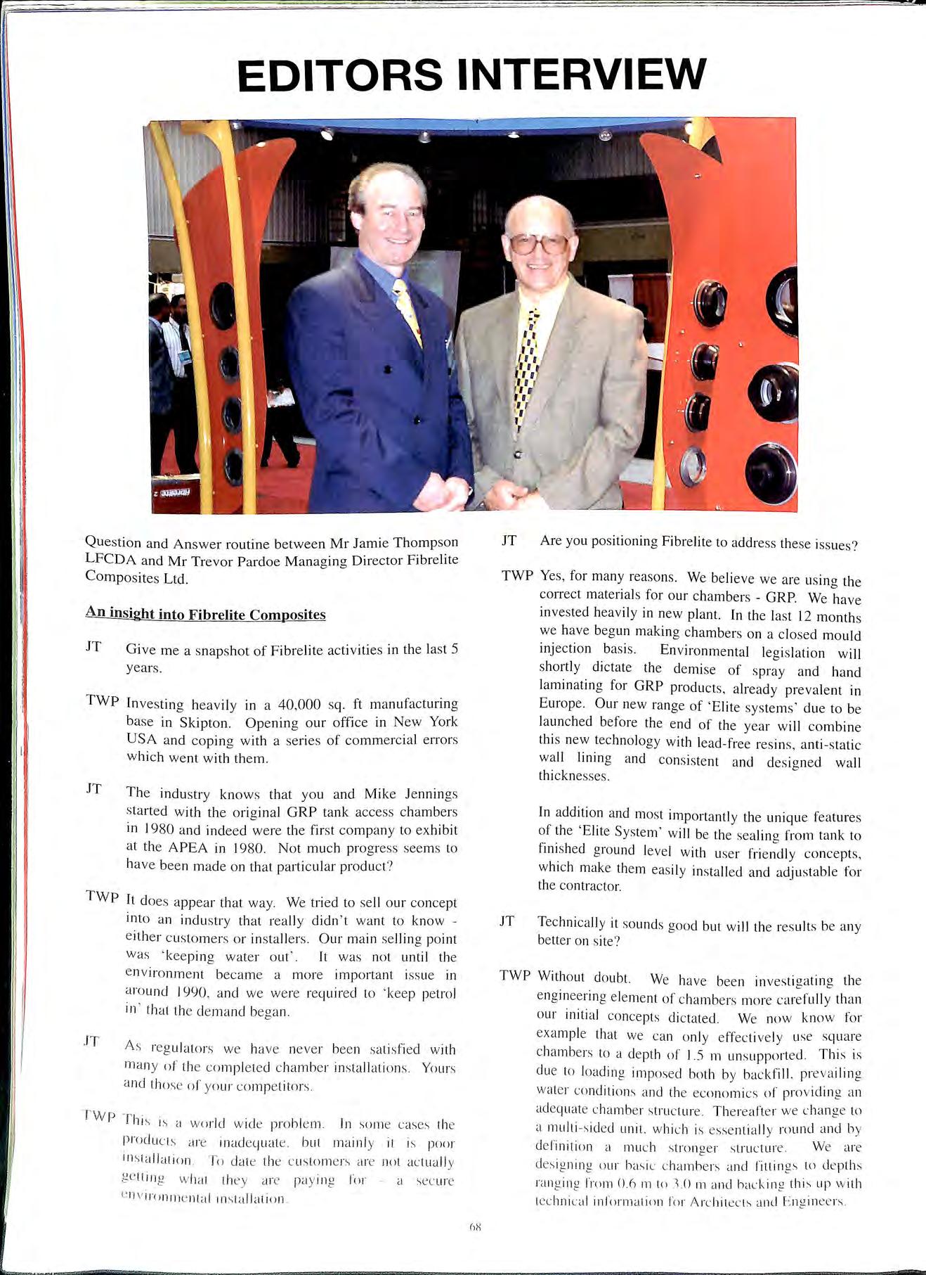
Question and Answer routine between Mr Jamie Thompson LFCDA and Mr Trevor Pardoe Managing Director Fibrelite Composites Ltd.
JT Are you positioning Fibrelite to address these issues?
JT Again it sounds good but will they work on site, keep out water and contain petrol?
TWP Not without accurate installation and this is where we have the ultimate solution the Chamber Testing System (CTS). Fibrelite will be able to offer an endorsement to our customers, a service or via a contractor a facility for certification. We have already installed many chambers using this checking device and the feel good factor is amazing. To think that previously you backfilled and then waited to see what happened somewhat unusual to say the least. The discipline imposed is welcomed by the contractors because they know they have done the job correctly and because of the unique nature and concept of the 'Elite System' of chambers and covers, it will also offer a retro-testing capability.
Using the CTS we will be able to check the integrity of the chambers from tank to ground level at any time or date after installation should this be required.
JT If you feel that you will be able to solve problems with chambers, do you need to concern yourself any further with the composite covers on the top?
TWP Again, before the end of the year we will be launching some new product concepts. The introduction of an 'Elite' chamber system will incorporate new wate1tight composite covers round and square, which actually work.
JT Why do you emphasise wate11ight covers?
TWP Because the 'Elite system' requirement is for a chamber that is free from water. The combination of the chamber, sealing kits and cover will give us a quality product that solves a problem always the Fibrelite principle.
JT You developed the first composite covers in 1985. Do you foresee fmther progress?
TWP Indeed yes. We now have lots of competitors 14 worldwide at the last count and we need to keep ahead.
JT How will you do that?
TWP For us it's all about quality, integrity and being cost effective. Fibrelite have always designed its covers to a recognised performance standard. Our competitors seem to design to a price. The product failures of our competitors have inhibited the acceptance of composites as a replacement for steel/cast iron covers.
JT You say that. but I notice that some competitors are now quoting BS references like EN 124 C250 and 8125.
TWP Yes. but they are irrelevant on their own and in many ways misleading. EN 124 relates to 1.netal covers and can only he used as a guide. Fatigue 1s the enemy of composites. excessive deflection creates delamination. Fibrt'lite covers have minimal deflection. minimal weight and rapid total renivcry. Many additional design have to be
JT
undertaken to ensure a product life of fifteen years our objective. Why are you so different then?
TWP Our covers are moulded in a monolithic way, no joints or bonding of separate pieces. This and the design concept elements overcome fatigue criteria. Our third party testing has proven to be difficult but invaluable.
JT Your competitors would probably disagree.
TWP Yes probably, but Fibrelite have always had to substantiate our claims to provide a future for a new industry. We have mortgages to pay and I believe a reputation to protect.
JT How do you compete against cheaper products?
TWP Essentially we can't on price. Total cost of ownership or long term view is a much more realistic position and many of our customers accept that management principle.
JT So what is next to keep ahead? It must be confusing for the customer when so many claims are made and there is no reference point?
TWP Here you have the crux of the matter. Composite covers are perceived not to work. There are too many subjective views and questionable third party endorsements from a range of companies.
The industry is now in need of design standards for covers. 1 understand that BSI will shmtly be publishing a new for composite covers upon EN 124 and spec1hcally .targeted at petrol filling stations. The BSI kitemark will be the reference point and will cover structural integrity, fatigue and water sealing.
How will this benefit Fibrelite?
JT TWP JT
TWP
1 believe that we will be able to comply with this new standard. Specifiers will be able to ask for this performance requirement. The kitemark should be king. It will eliminate potentially misleading statements by our co111petitors or indeed Fibrelite.
All co 111 panies have to do is achieve the standard and we can compete on equal terms. That doesn't happen at present.
And the future.
We are already providing grade D400 covers into certain highways in the llSA and even concreted standing areas in New York (Newark\ and Hong Konn c airports to specific Federal Aviation Agency (FAA l standards. We will pursue the future ur L"0111posite L'O\ ers as an alternati\'e to metal whne speci I"ic circumstances suit. but uur main thuught for the futurl' will be the nev. ·Elite Chamber Systems· nn 1wtrnl slat ions throughnut the wnrld. We \\ i11 pur-;uL' 11u 1 business un the back. uf innn\ation. intl'lkL'lua\ property right-. and defL'nding them ,, hnL· appn 1priate.
The New Regulations - Requirements for Monitoring Sites for Leaks
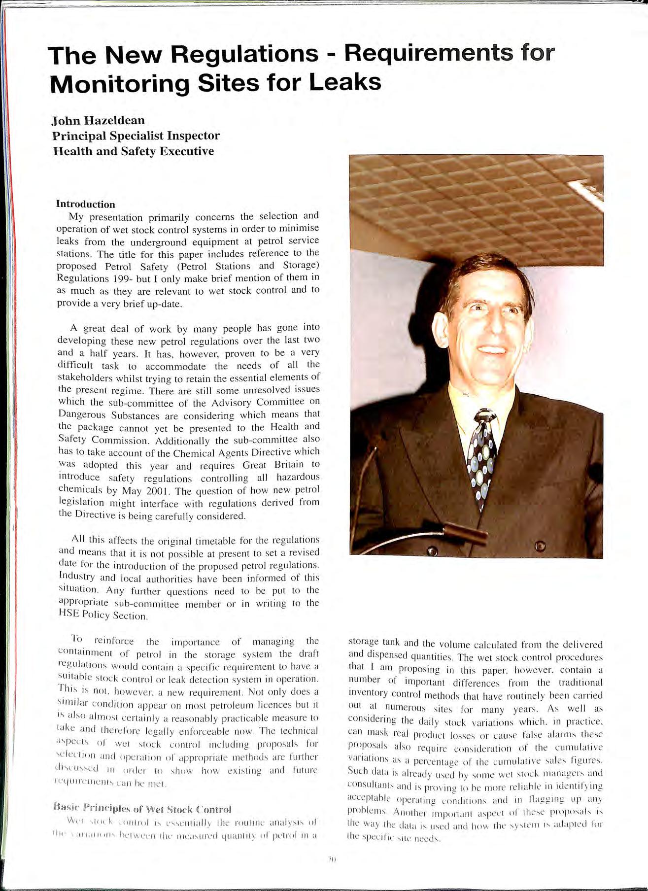
John Hazeldean Principal Specialist Inspector Health and Safety Executive
Introduction
My presentation primarily concerns the selection and operation of wet stock control systems in order to minimise leaks from th e underground equipment a t petrol service station s. The title for this paper includes reference to the proposed Petrol Safety (Petrol Stations and Storage) Regulations 199- but I only make brief m e ntion of them in as much as they are relevant to wet stock control and to provide a very brief up-date.
A great deal of work by many people has gone into developing the se new pe trol regulations over the last two and a half years . It has , however, proven to be a very difficult task to a ccommodate the needs of all th e s takeholders whilst trying to retain the e sse nti a l eleme_nts of the pre se nt regim e There are still some unre so lved iss ue s which the s ub-committee of the Advisory Committee on D a nge rou s Substances are considering which means that the package cannot ye t be pres ented to the Health and Safety Commi ss ion. Additionally the s ub-committee a lso ha s to t ake acco unt of the Chemical A ge nts Directiv e which was a dopt e d thi s year and require s Gre a t Britain to introduc e safe ty re g ul a tion s co ntrolling all haz a rdou s c hemi ca ls b y May 2001. The question of how new petrol leg is lation mi g ht interface w ith regulations deri ve d from th e Directi ve is bein g ca refully co n s id e re d.
A ll thi s affec ts th e o ri g inal timetabl e for th e reg ulati o ns and m eans that it is not poss ibl e at prese nt to se t a re vise d d a te for the intro ducti o n of the propo sed pe trol reg ulati o n s Indu s try a nd loca l a uth o riti es have been in fo rm e d of thi s s ituati o n. Any furth e r que s ti o n s need to be put to th e a ppropri a te s ub- com mittee member o r in w ritin g to th e H SE P o li cy Sect io n.
T o reinforc e th e imp o rta nc e of m a nag in g the c ontainm e nt o f pe trol in th e s torag e sys te m th e d ra ft reg ul at io ns wo uld co nt a in a s pec ifi c re quire m e nt to ha ve a s ui tab le s to c k co nt ro l o r leak d e tect io n sys te m in ope rat io n . T hi s is not h oweve r_ a new re quire m e nt. No l o nl y does a s imi lar co nditi o n appea r o n m osl pet ro le um li ce nces bul it is a lso a lmos t ce rtainl y a reaso nabl y p ract icab le m eas ure to lak e a nd th e re fo re leg a l Iy e n fo rceab le no w T he tec hni ca l a s p ects o f we t s tock co ntrol inc lu d in g propo sa ls fo r \C le uio n a nd ope ra tion of a ppropria te m e t hod s a re fu rth e r d J\L" U;,;,c d 1n md e r to s ho w how e x is t in g a nd future rc qu1r c rn c nt s c<in he rn e t
lft<1sk D.J>U"im:i ples of Wei Sioc k Control
Vvl'i s t!i Lk u> ntrnl 1s esse ntiall y th e rout ine anal ys is u J" 11J, · 1 C11 1;i l1<>11 s hL·l wcc n the 111ca s urnl qua 111i ty of pe trol 1n a
sto rage tank and the volume ca lc ulat e d from th e d e li ve red and dispensed quantitie s The we t stock control proc e dures that I am propo s in g in thi s pa pe r. how eve r. co ntain a numb e r o f imp o rt a nt diffe re nces from th e traditional in ve nt o ry co nt ro l me th ods that have routin e ly bee n c arri e d out a l num e rou s s it es for m a n y yea rs. As we ll as co ns id e rin g th e dail y stoc k va ri at ion s which. in practi ce c an mask rea l produ c t losses or ca use false alarm s thes e proposa ls a lso re quire conside rati o n of the c umul at ive va riation s as a pe rce nt al'.e of th e c umulati ve sa le s fi g ures S uc h clata 1.-; a lre ad y u-,e:I h y som e we t s tnck managers an d co ns ultant.\ a nd is pro v rn l'. lll he mor e re li a bl e 1n icle ntify 1ng acc e p tab le opera tinl'. a nd in fla gg in g up a n y prob le ms Anothe r irnpllrtant asp ect ll l th e se prnpusa ls is th e wa y the data is used a nd ho w th e sr lc'lll 1s adap 1e d 1u r the spec ili c \ it e nee d s.
I ' I '\ I \ !
711
The Need for Wet Stock Control
Everybody would agree that petrol leaks are undesirable but unfmtunately they still occur. Leaks from the petrol storage and transfer systems can create fire and explosion hazards both on and off the forecourt and will always give rise to environmental damage. The financial penalties from petrol leaks are severe both in terms of lost profit, possible fines and also from expensive remediation work.
A number of different regimes with the aim of preventing leaks have been established in the past but none have been completely successful. Such regimes have included tank inspection, inventory control, period tank testing, leak detection equipment and high integrity storage systems. All of these methods have had their successes but they have also had their failures often as a result of human error. Also a significant drawback for some of the systems has proven to be cost, particularly for the lower throughput sites. Wet stock control is seen as a basic system that is a reasonable practicable safety measure and one that can be introduced at different sites with different degrees of sophistication for the specific site risks.
Alternatives to Wet Stock Control
A suitable system should always be provided to prevent or detect leaks. Wet stock control is but one way of achieving that end and the proposals will allow other suitable alternatives as does the current regime. Selection of an appropriate system should be based on an assessment of the on and off site risks.
Various types of leak prevention or detection systems are described in the APEA/lnstitute of Petroleum document 'Guidance for the Design, Construction, Modification and Maintenance of Petrol Filling Stations' currently in preparation. The APEA/IP Guidance assigns leak detection systems into classes in accordance with a European Standard. Any system that has performance standards equivalent to those classes will provide an acceptable alternative to wet stock control for leak detection. Systems currently available that provide positive leak prevention and detection for both tank and pipes include:
Double skin tanks and pipework with interstitial monitoring (Classes 1,2 & 3)
Dynamic Leak Detection Systems (Classes 4a)
Statistical Inventory Reconciliation (Class 6)
Dynamic Leak Detection Systems are essentially tank contents measuring equipment hut with an in built and certified facility for detecting certain specified leaks from the tanks or pipework. Statistical Inventory Reconciliation is a sophisticated wet stock control system normally out by a third party and which has been assessed as. bemg capable of detecting certain specified leab. As with all safety systems it is essential these alterm.1tives are o.perated and maintained correctly and the appropriate action 1s taken when they give warning. As a back up to those alternative systems and as good management practice site operators are also advised to maintain good stock reconciliation records.
Essential Elements of Wet Stock Control
Returning to wet stock control I wish to hiohlioht the e e essential elements that are necessary to make the system effective. That is effective in both identifying a real loss, such as a leak, and also apparent losses, such a dispenser not being on strike or an incorrect delivery, which need to minimised or controlled as good management practice.
Good quality data is necessary and this may involve additional staff training. Any gaps in data collection, incorrect stock measurement or arithmetical errors will lead to inconclusive results.
Accurate stock measurement, taken at the same time each day, is crucial for reliable results. Tank contents can be determined using a tank gauge or a dipstick but either system may introduce inaccuracies in stock measurement. Dipsticks introduce inaccuracies as they are not usually calibrated to each tank after commissioning but on the initial tank dimensions which could have changed during installation. Additionally dipsticks can wear at the bottom, be used in the wrong tank, may be miss-read or provide inaccuracies because of the coarseness of their graduations. To avoid confusion each tank should be provided with its own dipstick and this should be labelled with the relevant tank number. A worn or bent dipstick will produce a variable e1rnr, depending on the level of product in the tank, which will make reconciliation figures impossible to interpret.
Gauges may be inadequately calibrated on commi;sioning or may not continue to function properly if they are not regularly or according to the manufacturer's instructions. Cahbrat10n may have been based on incremental fill using measured additions of petrol or on decremental fill a .meter pump itself could have unreliable calibration. Alternatively amioes may be calibrated against a dipstick which is itself 0 te Changes 1 ·n product and thus product density maccura . . · contaminants such as water or debris the installation of vapour recovery systems may all effect properly set up gauges.
As wet stock control is based around a tank or compartment accurate knowledge of th.e pipework is necessary so that only the 111to that particular tank or compartment and only dispensers drawing from it are taken into account for each tank reconciliation procedure.
I have already mentioned that the wet stock control system proposed relies heavily on the calculation or the cumulative variations as a percentage of the cumulative sales figures and this is discussed further when considering the analysis of the resu Its. Once the tank specific profiles have heen estahlishc.·d an) variance ahove an agreed limit is taken as an alarm level requiring action.
An essential elemL'lll of any wet stoL·k nmtrnl '>\ '>ll'l11 1.., regular auditing of the records to L'nsurc lhl'\ arl· mai ntai nL'd and intcrpreted correct l
Analysis of Results
Daily losses may show erratic variations particularly after deliveries or if the site is subject to external effects such as a variable water table. Although daily losses may not easily show small leaks they provide useful information in that they will quickly identify any sudden large leaks. The cumulative losses based on cumulative sales even out the irregularities caused by temperature changes and inaccurate stock measurement.
The cumulative losses based on cumulative sales will vary from site to site or even from tank to tank depending on factors such as tank throughput, tank size, product source and even the time of the year. They are normally in the range +0.1 to -0.4% but they can be higher and still be acceptable. Acceptable tank specific profiles for cumulative losses based on cumulative sales can be developed in a number of ways:
i) Based on the knowledge that the petrol containment system is sound and all unacceptable losses have been controlled. This will normally mean developing the system after having carried systematic checks on the containment system.
ii) By comparison with tank systems that are known to be sound and that are of a similar size and supplied with fuel from the same depot or refinery. Such tanks may be on other company owned sites or identified through trade organisations.
iii) reference to competent persons or specialists in the field of wet stock control.
Alarm Levels
Having est bi. ·h · · f h · a is ed spec1f1c tank profiles or t e cumulative lo. b t . sses ased on cumulative sales 1t 1s necessary 0 monitor th fluct em so that significant increases over a norm or uations wh · h · · bi are ·d .' IC may md1cate a leak or other pro ems 1 entif1ed p. fat · arameters need to be set which do not create se alarms and . tim d so undermme the system but at the same e o not all I · my ro . ow eaks to go undetected. The followmg are p posed alarm th ·h Id res o s.
• Two cons . . . each · ecutive months showmg an mcrease of 0.1 % month over normal.
o Three sue · cess1ve months showing an increase month on month.
Action When U
When the naccepta_ble or_Dnexplained Losses Occur thresholds it cumulative figures exceed the alarm investig· 1 is necessary to carry out a systematic a1on1nort fhc caus t er lo identify the cause of the problem. e may or m· . . identify th, ay not be a leak but action 1s needed lo . . e prohle111 . d . . . . spec1fic·it· an lo bnng the profiles back mto ' ion. Fve1 ·r persist l'OL I 1 • 1 1 II is not a leak variations if alloweu to 1 t n1·1sk 1· '· a uture leak.
\I"<'(' <>1nn1ended I • • 111\1:st1gal1on sequence 1s: r /1, ., k the 1 l"l'conciliation fiuures to ensure the 11 •1 11111 lie I!\ • I=. unrl'ct and that all deliveries and other ,. " I· ,, ·. ''llH·nh 11· , I d\ v Wen accounted for
ii) Check the wet stock control procedures are caITied out correctly and whether forecourt staff require additional training.
iii) Check for any obvious leaks from pipe joints in manhole chambers, electrical ducts, drainage systems and around the dispenser base.
iv) Check for any increases in petrol smells. Take into account any reports or complaints from neighbours.
v) VI
Check the tank contents measuring system. Check the dip stick for damage or the gauging system for coITect operation. Check whether tank gauges need to be recalibrated or serviced. Have the dispensers checked for accuracy.
vii) Check the tanks for water ingress.
vm Have the pipework tested for leaks.
ix) Have the tanks tested for leaks.
x) Consider fraudulent activities or short deliveries.
xi) Consider a temperature survey to identify any adverse temperature effects.
This procedure will enable the site operator to identify the problem with minimum cost. Only where an actual leak is identified or where the cause of the deviation cannot be determined should the enforcing authorities be informed.
At sites where wet stock reconciliation figures cannot be stabilised to provide meaningful results or brought within acceptable norms it will be necessary to reconsider the wet stock control process. Where tanks and lines have been tested and proven to be tight further improvements in leak detection and control may be achieved from one or more of the following options:
More accurate tank gauging systems.
Increased frequency of data collection and analysis. Computerised data analysis.
Statistical Inventory Reconciliation by a third party. Positive leak detection systems.
Selecting a Wet Stock Control System for a Particular Site In accordance with other guidance issued by HSE it is necessary when selecting control measures for safety to undergo a risk assessment procedure. Separate guidance on risk assessment has been issued by HSE but essentially it is a procedure for determining whether the control measures provided are sufficient to prevent harm to people or whether more should be done. For leak detection systems. including wet stock control methods, this means not only taking into account the ability of a particular method to detect leaks in differing circumstances but also considering the likelihood of a leak and the consequences of that leak should it occur and remain unuetected.
As an aid to risk I have ranked detection and prevention systems in an oruer based on their potential for identify and preventing a leak. Specific variations arising from different equipment. and operational procedures may. ho\\ ever. gi vc rise to some overlap hetWL'l'll the ditlncnt groupings hlr L'Xa111ple there are
-r------i i ; I
,_,
different tank gauges available offering various degrees of precision or in-house computerised data analysis systems may not be as user friendly as proprietary systems. For this reason the following rankings should be considered as a guide so that other specific site or operational matters can be taken into account if necessary:
Dipstick or gauge with weekly manual reconciliation
increasing ability to detect or prevent leaks
2. Dipstick or gauge with daily manual reconciliation.
3
. Dipstick or gauge with computerised data analysis.
4. Positive le ak detection system
5. Statistical Inventory Reconciliation.
6. Positive leak prevention system.
These rankings can be correlated with different site rankings using a matrix which takes into account the major factors relating to the possible consequences of a leak that may arise from different locations , throughput and material of construction of the underground equipment.
This selection procedure only considers the main areas which need to be addressed. As sites differ there may be other site operations , underground conditions, equipment, control measures or site specific factors to be taken into acco unt when deciding what is necessary and feasible for the specific circumstances A separate ranking table can be developed for GRP tanks and non metallic pipe work.
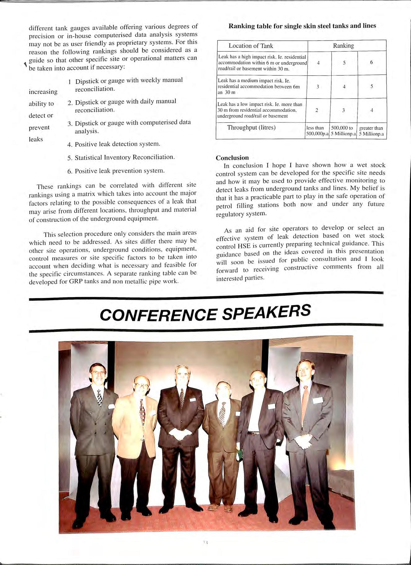
Ranking table for single skin steel tanks and lines
Location of Tank
Ranking
Leak has a high impact risk. l e. residential accommodation within 6 m or underground road/rail or baseme nt within 30 m. 4 5 6
Leak has a medium impact risk. le. residential accommodation betwee n 6m 3 4 5 an 30 m
Leak has a low impact risk. le. more than 30 m from residential accommodation 2 3 4 underground road/rail or basement
Throughput (litres)
less than 500,000 to greater than 500.000p.a 5 Millionp.a 5 Millionp.a
Conclusion
In conclusion I hope I have shown how a wet stock control system can be developed for the specific site needs and how it may be used to provide effective monitorina to b detect leaks from underground tanks and lines. My belief i s that it has a practicable part to play in the safe operation of petrol filling stations both now and under any future regulatory system.
As an aid for site operators to develop or select a n effective system of leak detection based on wet stock control HSE is currently preparing technical guidance. This guidance based on the ideas covered in this presentation will soon be issued for public consultation and I look forward to receiving constructive comments from a ll interested parties.
CONFERENCE SPEAKERS
7 '
Method and Apparatus for Monitoring Operational Performance of Fluid Storage Systems
Dr Warren Rogers
Abstract
Wet Stock Control techniques are likely to be featured in United Kingdom regulations. Raised to the highest level of sophistication, Wet Stock Control embodies Statistical Inventory Reconciliation procedures in both manual and automated systems.
Introduction
The Technique of analyzing petroleum inventory records by statistical means was developed by Warren Rogers Associates, Inc. in 1981 in the United States. The primary objective in doing so was to improve the leak detection sensitivity achievable by traditional inventory control practices. Doing so, however, required the ability to identify and compensate for all of the systematic and non-leak related errors which routinely enter inventory measurements and are an inevitable part of inventory control methods as have been traditionally practiced. The goal of precision mventory management is therefore achieved as an integral part and essential component of Statistical Inventory Reconciliation (SIRATM).
Scope of Presentation
inventory management entails identifying, measurincr and q t"f · II f "' uan 1 ymg a o the systematic sources of variance in 1 ·nv t d· en ory ata so that the residual variance consists only of the irreducible random e1Tors inherent in the measurincr d · Th. · · "' ev1ce. is 1s exactly what is done and must be done by SIRATM · m order to detect leaks. In short, SIRATM achieves the croal . f . . . · "' s o prec1s1on mventory management as a precondition to accurate leak detection.
Petroleum invent d· t ory ata rs subject to systematic errors rom a variety of . sources. Very prominent and very common among them is inac . h . h · curacy m eight to volume conversions w ether by entry f I . ·fr . . 0 manua stick readings into conversion c arts or by comp t t' b 1 h'. u a ran Yan automatic tank crauge (ATG). n t rs context w h· "' . . . e ave found m the United States that approxrmately 50 pe f . h· , r cent o systems usmg manual strckmcr a\ e mcorTect conv . .- h "' of A'TC' eision c arts, but as many as 80 per cent tt 1 mstallatrons · · are improperly programmed.
A very common p bi ro em 111 this context is a failure to conectly account for· . k . . . tan trlt. Tank manufacturers provide cunvers1011 charts th· t . . . . . 1 .. . · c1 are appropriate only if the tanks are l<111mn1ally mstall ·d S. d· . c · t<1n ar d 111stallat1on practice however p1ov1de.., for some d o. ' t' 1• ee o tilt to concentrate sludge l epos1ts away from sub , "bi · mc1 s1 e pumps. ATG manufacturers mah matter.., wors, h . · · , e Y p1 ogra111111111g a correction into their gau/ln. which would b . . · . e app1opnate only 1f tanks were of I L'l'lit!l).'.U lar cross section.
l'n 1hl 1·m.., wi1h l1t·1·g11 t I · · , 1 o vo ume conversion 11111l1111 · 1<1 1111 f1· ·1111· , • 11 · · I · ' · • l p.t c1 n.., 111 t 1e 1nven1ory data and !hey " 11 1hn!'fo1-.· he rcadil) idc111ified and corrected. New '>II· l'l'dl II I , . h I 1 1.11 ' ' .in v LTl'aln Irom !he 111vcn1ory dala and
ATGs can be reprogrammed to provide correct conversions. This is the essential first step towards precision inventory and is an absolutely essential pre-condition to achieving it.
Once height to volume conversions have been calibrated, ongoing and recurring errors can be identified and corrected. These include averages and underages in delivered quantities, meter miscalibration, unrecorded additions or removals and, of course, theft. Finally, the analysis ensures that all systematic effects have been accounted for and that the final residual variance reflects only the random variation induced by measurement error.
It also, however, quantifies that residual error and informs the operator as to its implications and what steps could be taken to reduce it. This can be done, for example, by computing minimum detectable leak (MDL). That is the smallest leak that could be detected given the size of the measurement error.
SIRATM can be conducted in a great variety of ways at various levels of sophistication and expense. At its simplest, the routine inventory data cmTently collected is forwarded monthly for analysis. No additional equipment or activity is required. The data is analyzed and a report is returned within five days listing all of the errors detected and the revised inventory variance.
At the opposite extreme is our PetroNetwork I On-Site Processor (OSPTM) system. This system is completely automated, requmng no input by the operator. It automatically extracts product height and temperature from an ATG, collects sales data from the dispensers, and combines them in an on-site processor for real time. continuous analysis. The comparative capabilities of the systems are as follows.
Fully Manual System
:i l ! I I .1 ' I 1, I '.I I j
+ Height to volume conversion charts generated or ATG reprogrammed + If only single observation per day. 30 days of data required to generate new conversion chart (programming) and 30 further days to confirm + Delivery discrepancies between invoiced and ac!Ual deliveries are determined + Overall metering discrepancy (total cli..,crepancy. all hoses) + One time unrecorded acldilions or removals. e.g. !heft + Reporling frequency weekly or monthly
+ Typical leak detection capability with consistent sticking, 0.1 gallons per hour
+ Operator must stick tanks or read ATG and record volume and sales for each 24 hour period
+ Not suitable for very active sites receiving one or more deliveries per day. Delivery shortages would be indistinguishable from leakage. Multiple stick readings per day impractical unless temperature corrected
Fully Automated System
+ No operator involvement
+ Conversion chart correction and verification in five days from installation
+ Actual volumes delivered computed at time of delivery within plus or minus 0.5 gallon
+ Hose by hose meter discrepancies computed
+ All computations temperature corrected
+ Reporting frequency daily unless unusual event detected e.g. onset of catastrophic loss '
+ Ability to shut down system if catastrophic loss detected
+ Can distinguish between tank and line leakacre at rates of .0 I gallons per hour 0
+ The system can be provided with ATG or can be retrofit to any existing ATG system
automated configuration is an open-architecture design can interface with major dispenser pump control devices and automatic tank gauging systems. It can be remotely and is Microsoft™ compatible. In add1t10n, all PetroNetwork OSP sites can be linked into "d a w1 e area network providing real time wet stock management functionality for a large population of UST's.
LPG CODES OF PRACTICE
At the APEA Exhibition many of the queries asked at the ALGED display related to technical matters and standards used within the LPG Industry. For the benefit of those who did not attend or who did not obtain sufficient information listed below in a priority order is a selection of Codes of Practice obtainable from the:-
LP Gas Association Pavilion 16 Headlands Business Park Salisbury Road Ringwood Hampshire BH24 3PB
The prices include postage & packing for the UK but add £I 0.00 per order for overseas. Discounts are available for LPGA members (25% full members lOmn ·iffi·1· t b ) · · x ' ta e mem ers
CoP I Part 1. Design, Installation and o t" f , pera ion o Vessels Located Ground (July 1998) £40.00
This is the mam document used througllotit th I d e n ustry. It supersedes both the 1991 edition and the H.S.E. document HS(G)34 which has been withdrawn. It comprises 9 comprehensive sections covering plant location and safety distances. design of the vessels and associated equipment. fire electrical requirements. installation and comm1ss1onmg. and operations and records.
LPG Technical .Fundamentals (1997) £19.00
As well as the physical and chemical properties of LPG this document also explains the different methods or storage. the supply chain. the use of cylinders and hulk storacre includi11!! buried versions. This hooklet is essential "" rading for those who need to understand the fundamental technology of LPG for safely in design. installation or use.
CoP 22. LPG Piping System Design and Installation (February 1996) £24.00
CoP 20. Automotive LPG Refuelling Facilities (June 1998) £22.50
This code covers retail commerciala nd industrial facilities, sets out minimum separation distances between the various items of plant and also gives area classification zones.
CoP 14. Hoses for the Transfer of LPG in Bulk. Installation, Inspection, Testing and Maintenance. (February 1998) (19.00
This covers the hoses used on Autogas installations.
CoP 3. Prevention or Control of Fire Involving LPG (July 1995) £16.60
CoP 1 Part 3. Periodic Inspection and Testing (October 1986) £16.60
LPG installations require rigorous routine inspection and testing. This code sets out the minimum requirements for a scheme of inspection and major examinations.
Also of interest may be two out of date codes. CoP 18 _ Safe use of LPG as a Propulsion Fuel For Boats. Yachts and other Craft ( 1981) £ 13.60. and also CoP 19 Liquid Measuring Systems for LPG ( 1982) £ 16.60. CoP 19 is being revised.
This is just a personal selection of the over 30 codes published which would he of most use and interest to those encountering Autogas for the first time. whether from the enforcement role or as operators.
Other enquiries related to n•hicle nnnersions equiplllL'nt l.P(I suppliers. Details or these can he obtained L'ithn from the LP(IA or from ALGED. of whid1 lhL· rnrrent senetar) 1s Mr Rill Barnett. Tel/Fa\ no()\ L)()) 7LJ)
APEA Presentation - October 1998
'Terminal To Nozzle'
By Thomas Haar, Alfons Haar GmbH, and David Wilson, Tuthill Corporation, Emco Electronics
Introduction
Alfons Haar & Emco Electronics, leading companies in the tank-truck and underground storage tank monitoring equipment markets, have combined to provide the industry with a solution for fuel management from the terminal to the dispenser nozzle. This "Terminal to Nozzle" concept is coupled with the ability to remotely monitor all fuel management functions, including the environmental compliance of the forecourt.
Driven by the need for loss reduction, the industry has been seeking complete management and control of the fuel transport from the 'Terminal To Nozzle'. Partial solutions are already in place due to developments meeting various national safety and legislative requirements.
Taking advantage of these partial solutions and with local networks, such as P-Net, for the tank truck and IFSF for the forecourt, it is possible for the total 'Terminal to Nozzle" management and environmental control to be integrated.
Remote monitoring of all, gantry, tank-truck, and service station product movement now becomes a reality, coupled with the ability to remotely monitor the site for environmental compliance.
Concept
'Terminal to Nozzle' concept, using the truck computer as the master data collection device. is based on the fact that the truck is an integrated part of the gantry system during loading and, in the same way, it is an integrated pm1 of the forecou11 during offloading. A closed data communications link, with the tank truck as the controller, is established. This gives the ability to integrate communications, both at the terminal and at the forecourt with minimum investment.
On board the truck a level of intelligence is installed which controls data collection. processing, and storing. This intelligence also provides the gateways for both the gantry and forecourt communications. as well as the GSM communication with the remote Control Office. GSM communication is event hased. which means that events such as loadin11 and offloadina can 11enerate an automatic c c c transmission of data to the remote Control Office.
The system provides the maximum possible features. yet i-. totally f"lexihle due to the modular field bus design. so that pro/!re-.si \l' development of tailored requirements can be achieved
f'ht· tan"n tour plan. IA h1ch includes the loading r11·qµr;m1111L' 111<1\ hv ren·i\L'd ll!l hoard \'ia (ISM lll' with the 11 s1J;d tf0t·11111v111 lrail
Before the terminal loading process commences, the onboard intelligence checks the dry status of the compartments and lines. This intelligence is linked to the gantry Overfill Prevention Controller so that in the event of retained product being present on the tanker, loading will be prohibited and cross-contamination prevented.
The correct assignment of loading arm, compartment, product, and volume is achieved by identification of the loading arms. This identification is a CEN Standard using either a binary code formed by magnets or tags, and the loading arm assignment is an important part of "Cross Over Prevention" and overfill protection. This ensures that the correct compartment volume is loaded with the designated product. It also ensures the c01Tect distribution of the load, a safety aspect on the road, and the correct combination of meter pre-set and compartment size as additional overfill prevention.
_Data_ connection between truck and gantry is made by usmg either the overfill prevention cable, infra-red or low power radio.
loading plan may be transmitted to the gantry mtelhgence, together with the truck identification. This way. depending on the level of automation on the gantry, a fully mode of operation is possible, including automatic pre-set of the gantry meters.
On completion of the loading operation. all the metered data with the identified product data specifications, are transmitted to the truck intelligence.
The truck receives a gantry departure report. and dependant on local regulation may be in the form of either temperature compensated volume, or the non-temperature compensated units. This is the first event of the complete operation of. transporting fuel from the gantry to the forecourt, which can generate an automatic transmission of all the collected data via GSM to the remote Control Office.
The truck leaving the terminal now has all the hase data on hoard to ensure "Terminal to Nozzle" reconciliation may become a reality.
Transit
The truck i I I · · A s a sea el urnt n) unauthorised tampering will he detected logged h) the truck controller. The onl) "ariation al this stage he the temperature-related of' product. Through the analy-.is of the departure report. can he quantified upPll arri \al at the l'orccourt
i ,j I
THOMAS HAAR
Forecourt
On a rrival at the fore co urt , the tru c k is connected fir s t to th e tank gauge or IFSF bu s , vi a infr a- red or low pow e r radio link. The truck mtellt ge nce identifies the station and read s the environmental status and tank contents via th e tank ga uges (DCD 0 .peration ). If the gauge sy s te m is adequately equipped , it can al so re port the la s t delivery with d a te a nd time to check. for un sc heduled intermediate fill s. Thi s d a ta 1s then tran s mitted vi a GSM a s the Foreco urt Arrival Report.
The ta n.k gauge readout ca n be u sed to ide ntify th e ulla ge ava ilabl e 1n each tank as preve ntati ve checks for overfill. Rea l time overfill preventi o n durin g the product dro p ca nn o t ac tually be based on th e ga uges and the fi e ld bu s clu e to rea l time communication probl e m s. H owever, o th e1 '. so luti o ns a re av ailabl e to fulfill th e need s of ove rfill preve nti o n
E n v iro nm e ntal monito rin g is a n impo rt a nt e le me nt of th e I ·t· S)' ste in and in so me a reas th e tank e r tru c k has oreco ur · b th e key to e nforce me nt of th e e n v ironm e nt al eco m e
I. ce rea ulation s. Th e refo re the ab ilit y for th e fu e l co mp tan "'
I to cJ e te rmm e th e 1nteg nt y o f th e Ju e l handl111 g s upp 1e1 . _ _ _ sys te m a t th e s ite 1s a n imp o rtant pre requ1 s 1te to th e de li ve ry of the fu e l. Th e tank ga uge e n v ironm e nt a l comp li a nce s ta tu s re port ca n be use d hy th e truck c omput e r to co nfirm that th e ta nk a nd assoc ia ted lin es are fr ee t'rnm po ss ibl e ri s ks th at would ne L·ess it at e in ves ti gat ion prior tu de li ve ry of product to th e s it e
To maintain Cross Over Prevention security, a system is required to assign the compartment, hose and tank Such sys tems, as used at the te rminal , are CEN approved and commercially available.
Three versions of tank truck deliveries are available:
"Sealed Parcel"
Metered product discharge
Split compartment drops , using the on board tank gauge, or calibrated forecourt tank gauge
Before the individual bottom valves open , th e truck is checked to ensure that conditions were as exi s te d when the truck left the gantry.
Service Station Component of "Terminal to Nozzle" Control
This sector may be split into four components:
Communications at the Forecourt
The truck mu s t be abl e to cany out the norm a l "Driver Controlled Deliv e ry " functions. The e nvironmental condition of the site and the tank ullages are verified u s in g the tank gauge data At thi s stage the tank ga u ge m ay be interroaated to obtain d e tail s of the last d e live ry to s ite, a nd at the of the de livery the ne t volume .gain of product is communicate d to th e tank truck and th e s ite b ac k office. Another se t of d ata 1s transmitted to th e tank tru ck to complete the audit trail.
Delivery Confirmation
The delivery co nfirm ation at the forecourt mu s t be t be O f a ri y useful value. In order to o bta in accurate o < d ·eli.abl e informa tion , ta nk gaug111g with well accurate an 1 prov e n techniqu es mu s t be used. The c urre nt ga u ge is th e · · 1 111 a a net os tri c ti ve prob e used 111 und e r gro und ongma ' o storage ta nk s Thi s probe has th e bes t ' 'track reco rd" , a nd is of stainless s te e l co ns tructi o n with exce ll e nt re pea ta bilit y and reli a bility. Many ten s of thou sa nd s of th e se magn e to s tri c ti ve probes ha ve bee n in reliabl e se rvi ce for year s
A re liable ga uge ca n be tun e d to good tank ca libration which le ads to acc urat e vo lum e m e a s ure m e nt. The tank ga ug in g sys te m w ill t he n be a bl e to re cord th e d e li ve ry This de li ve ry in for m at io n mu s t be compe nsa te d for w ith th e vo lum e w hich ha s bee n disp e nse d from th e pump s durin o th e d e li ve ry. Th e tank ga u ge will also rec ord te mp e ratur e of th e product. in th e und e rground s tora g e tan!-.. al th e tim e of d e li ve ry a nd at the co mpleti o n ur th e d e li ve r) c ycl e
Thi s d e li ve r)' in for m a ti t1 n s uppli e d b ) th e tank 1 ' ::- " th e nex t s ta ge in th e '"Tf rminal tll No11 k rt'L' 1\nl 11ta 111 ,n
1.
2.
3.
1
2
3.
4.
Communication s at the Forecourt
Delivery Confirmation
Sales Recon c iliation
Environmental Monitoring
cycle. The volume of product delivered the or the truck to the tank is reconciled at the time of delivery to confirm that no product has been lost in the transportation process from the terminal to the fore_court. Prior to departin g from the site a departure report 1s generated and transmitted to the remote Control Office.
Sales Reconciliation at the Forecourt
The tank gauge is able , if connected to the "point of sale" terminal , to interroga te the dispenser totalisers a nd hence be able to automatically reconcil e the volume being dispen sed with the volume being withdrawn from the tank. This is a continuou s method of checking the security of the tanks and lines, and will also give sudden, unauthori sed loss warnings and alarms.
This is the final stage m " Terminal to Nozzle" reconciliatio n
Possible Error Sources
The following are the immediately identifiable pos sible error so urces:
Source Error Magnitude
Terminal meter Weights & measures tol erance
Vapour losses , returned 32 to 80 litres in a 40,000 to truck litre tank
Temperature volume 1% for 10°C variation
SG variation (fl oat gauge s) SG range 57 60 APT : 5 litres in middle of the tank\tab
Di spen s ing meters Environmental Mon
itoring
Weights & measures to lerance (s hould average 0 over the site )
On ce tank ca librati o n has been performed it then becomes poss ibl e to de tec t th e sudde n los s of produ c t as might occ ur due to a catastrophic leak, the ft , o r me ter fa ilure at a pump When coupled wit h stati c or dyn ami c lea k de tect io n tec hniques and monitorin g sensors, th e tank ga ug in g sys te m will prov ide loss detect ion and of all sys te m co mp o ne nts o n th e for eco urt.
C onclusion
A ll t he co mpon e nts a re now in place , prove n and in c urre nt pro du ct io n to make "Te rmin a l to No zz le' " re c on c ili a tion a re a li s ti c o pti o n "C ro ss Over Preve nti o n" o n board DCD o n ta nke r me te rin g . ta nk truck de li ve ry re co nci li a ti o n. e n viro nm e nta l mo nito rin g a nd tank to nou le rec o nc ili at ion a re a ll c urre ntl y ava il ab le
By far, th e largest ind ependent variable remain s the variation in prod uct temperature as the product moves fr o m the termin al to the no zz le In some countries it is a lready mandatory to ha ve temperature compe nsated deliveri es, however, in many loc ati o ns " lo sses" as sociated with te mperature are unc on troll ed and all owed to mask rea l losses th at are controllable. Terminal to No zz le recon c iliation allow s measurement o f the apparent and rea l losses in the syste m, and iso lation of losses that can be red uced to pro vide impro ved product co ntrol. The te mpe rature as meas ured in the unde rground storage tank. prior to and after de liv ery, makes the audit trail poss ibl e.
Remote Monitoring
With the Haa r Em co re mote monitorin g burea u. it is poss ibl e to comb in e s ite e nv ironm e nta l monitorin g. in c ludin g S LR (s tati st ica l in ve ntor y recon c ili ation) w ith "Te rmin al to Nozz le' · reco nc ili ati o n and log isti cs fo r orga ni s in g distr ibu tio n and impro ved fue l ma nage me nt.
DAVE WILSON
DAVE WOLFE & SOME OF HIS "VICTIMS" AT THE CONFERENCE DINNER
79

I • • XO
XI
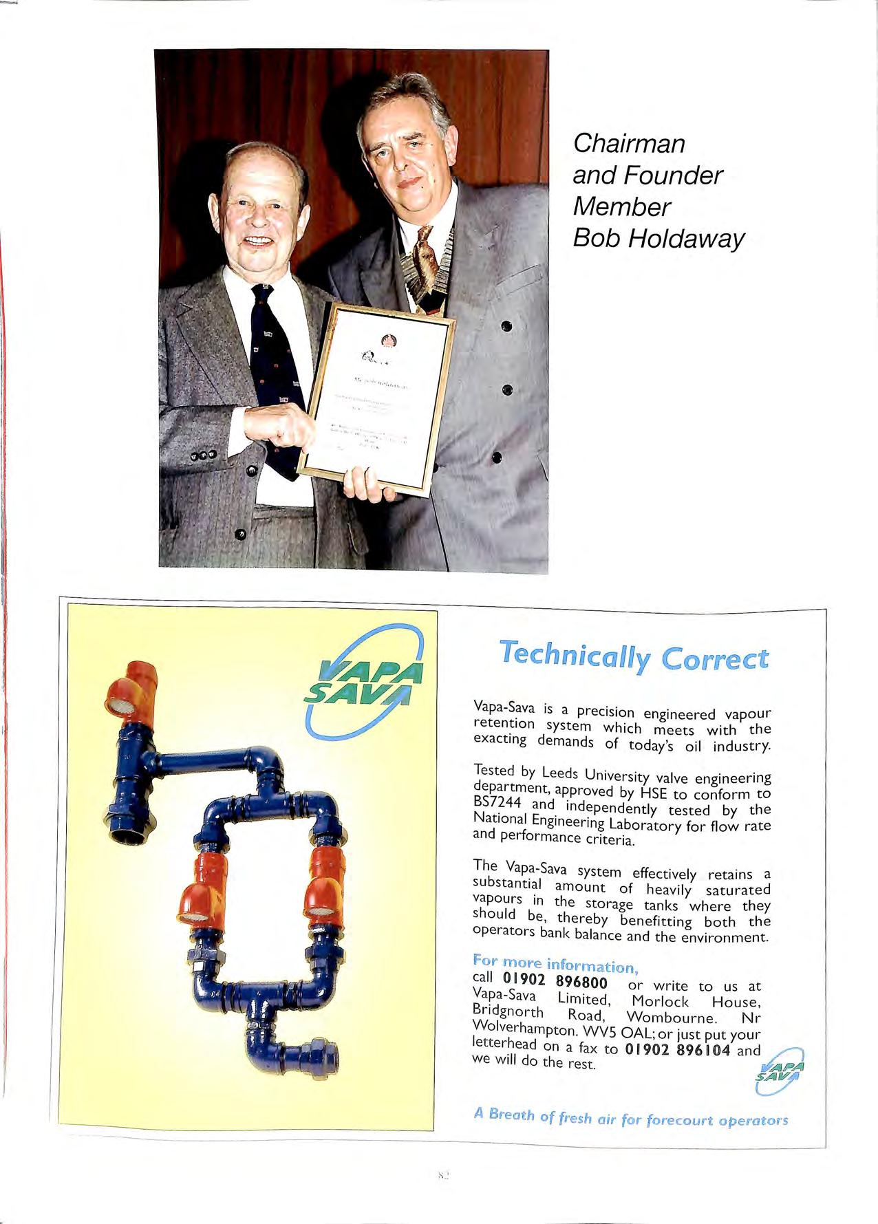
Chairman and Founder Member Bob Holdaway
ec:hni a lly Co rrect
Vapa-Sava is a prec1s1on engineered vapour retention system which meets with the exacting demands of today's oil industry.
Tested by Leeds University valve engineering department, approved by HSE to conform to BS7244 and independently tested by the National Engineering Laboratory for flow rate and performance criteria.
The Vapa-Sava system effectively retains a substantial amount of heavily saturated vapours in the storage tanks where they should be, thereby benefitting both the operators bank balance and the environment.
for more information, call 01902 896800 or write to us at Vapa-Sava Limited, Morlock House, Bridgnorth Road, Wombourne. Nr Wolverhampton. WVS OAL; or just put your letterhead on a fax to O1902 896104 and /I we will do the rest.
A Breath of fresh air for forecourt operators
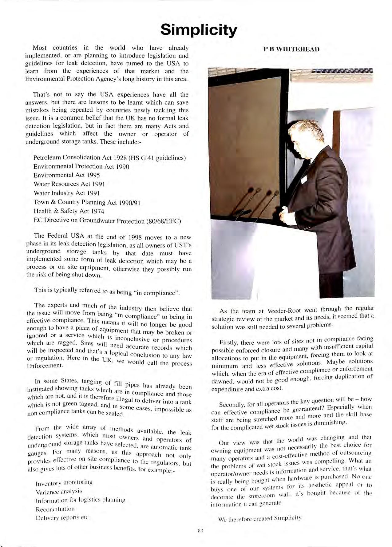
Simplicity
Most countries in the world who have already implemented , or are planning to introduce legislation and guidelines for leak detection, have turned to the USA to learn from the experiences of that market and the Environmental Protection Agency's long history in this area.
That ' s not to say the USA experiences have all the answers , but there are lessons to be learnt which can save mistakes being repeated by countries newly tackling this issue. It is a common belief that the UK has no formal leak detection legislation, but in fact there are many Acts and guidelines which affect the owner or operator of underground storage tanks. These include:-
Petroleum Consolidation Act 1928 (HS G 41 guidelines)
Environmental Protection Act 1990 Environmental Act 1995
Water Resources Act 1991 Water Industry Act 1991
Town & Country Planning Act 1990/91 Health & Safety Act 1974
EC Directive on Groundwater Protection (80/68/EEC)
The Federal USA at the end of 1998 moves to a new phase in its leak detection legislation , as all owners of UST's und e rg round storage tanks by that date must have implemented some form of leak detection which may be a process or on site equipment , otherwise they po ss ibly run the risk of being shut down.
This is typically referred to as being "in compliance" .
The and much of the industry then believe that the issue will move from being "in c 1 ,, b · · omp iance to erng 111 effective compliance. This means 1·t w'll 1 b d 1 no onger e goo enough to have a piece of equipment tl t b b k 1a may e ro en or ionored or a service which · · o rs 111conclus 1ve or procedures whi c h are ragged. Sites will d . . ne e ac c urate re cords which will be mspected and that's a looical 1 or regulation. Here in the UK 0 c cone us1on to any law ' we would call the proces s Enforcement.
In some States , tagging of fill i e s in stig ated showing tank s which ar _P p !Ms already bee n d · · e 111 comphance and tho se which are not, an It rs therefore 11 1 I eo a to dehve · t k h h ·s not green taooed d . 0 I 111 o a tan w 1c 1c oa , an 111 som · k e c a ses, impo ss ibl e as no n c omp!Iance tan s can be sea led
From th e wide a rray of method s av a il abl e th e lea k de tec tion system s, whi c h mo st owners and operato rs of de roround storage tank s hav e se lec te d . . un o , a1e autom a tic ta nk ga ug es For many reason s. as_ thi s a pproach not onl y provid es e ffe c tive o n site co mpli a nc e to th e reg ulat o rs, but a lso gi ves lo ts of o th e r bu s111ess be nefit s . for exa mpl e :-
lnv e nto ry monito rin g Vari a nce an a lys is
In fo rmati o n for log ist ics pl a nnin g Rec on c iIia ti o n De li ve ry re ports etc .
A s the team at Veeder-Root went through the regul ar k d ·t needs it seeme d that <: strateo1c review of the mar ' et an 1 s ' b solution was still needed to several problems .
. f . t in compli ance facing Firstly, there were lot s o sites no . .. . . . vit11 ll1 Sufhc1ent capita] po ssible enforced closure and many \ . 1 k . t forc mo them to oo at alloc ation s to put in the ' M a be solution s d I , effective solution s . y m1111111um an ess 1· o enforcem e nt h . h t1 f effective comp iance I w 1ch , w en 1e e1a 0 f' · dupli c ation of d e nouah 01c1ng < dawned , would not be goo o ' expenditure and exu·a cost.
. . tl e key qu es tion will be how
Secondly, for all opeiatoi s 1 . t d ? Espec ia ll y wh e n l. e be auman ee · c an e ffecti ve comp ianc 0 d ·e a nd th e s kill ba se I d mo re a n 11101 staff m·e belllg stre tc 1e d'mini shin <> . d t tock issues 1s 1 ' 0 · for th e comp!J c ate we s
Id wa s c ha ngin g a nd th a t · h t t 1e WO!
J
Our view wa s t a .. 1 th e bes t c hoi ce for t was no t necess.:u I y ownmg equ1pm e11 < ie thod of o utsourc in o d os t- e ffec t1 ve n · · o many o pe rato rs an a c k . sL1 es was co mp e llin g What a n I l I o f we t stoc is, · t 1e pro) em s · cl s·e1·v1·ce tint' s w l1 11 · · formati o n dll · · ' · ' ope i"H o r/ow ne r needs is Ill N ' 1 n hard wa re 1s purc hase d o o ne · · II l1 e mo bo u<> ht w 1e 1s 1ea Y o c ' tll e'ti c 11Jpt" 1l or \') ' te rn s to r it s des ' ' ' bu ys o ne oJ our sys · . . · wa ll ifs bou g ht becau se o t th e deco rate th e sto1 e1oo m < • inform ati o n it c an ge ne rate.
We th e refo re crea ted S impli c it y.
PB WHITEHEAD
This is a product where we provide at no capital cost a high spec tank gauge. We retain ownership and maintain it.
We also communicate with it via satellite or modem on a 365-day x 24-hour basis and we provide back to the site, information tailored to its specific needs or requests.
For example, leak detection reports. Each month the site gets a report in an approved format USA EPA or UK to file on site and we keep records and history as back up. If an inspector calls, the site has the answers to hand. It can demonstrate effective compliance.
What if something goes wrong an alarm, a leak, perhaps equipment issues?
Here the gauge automatically dials out to our Control Centre and one of the Controllers will take action to verify the position and, if necessary put it right. This may be by despatching a Service contractor or calling the site to alert them to do something.
One of the highest cost items in fuel retailing is the cost of distribution and here, using Simplicity, a lot of money can be saved.
By getting real time data on the tanks ullage, distribution can plan cost-effective routings, ideally turning the process from a pull system to a push system. In other words, avoiding rush or expensive routings.
The Veeder-Root equipment predicts usage and the optimum time for delivery and provides this information to the delivery schedulers. They can then plan fleet usage economically and ensure the retailer always has stock but not too much. The most effective normal retail situation is the lowest amount of cash tied up in stock, but never any runouts.
Also we have found this process helps balance stock between slow and high moving lines. as typically the unleaded delivery needs drives up stocks of 4* and diesel, again hitting retailers cash flow.
For the distribution operation as well, this minimises risks of ove1i'ill or haul back as regular information on tank status is possible right up to despatch and even at delivery with Driver Controlled Delivery systems which can also be included in the Simplicity package.
The other service which can save money using Simplicity is Variance Analysis or Loss Analysis. as we sometimes know ii. When sites reconcile at minus 0.2o/t to CU% of lhroughput. there is not usually much excitement as lemperal ure and evaporation offer the rationale. However. when these figures rise lo. say 0.4o/t O .'io/t or more. alarm bell.\ he nnging. Why'.1
Firstly, because its money lost. Imagine the money saved across a network of only points of % of throughput loss being avoided by quick action on problems, and secondly, it could be an environmental or safety risk. This approach is the common method of leak detection used in the UK.
There are lots of reasons for variance changes in addition to temperature, evaporation and leaks. Meters over dispensing are a common problem, as are thefts or what is known as transfer loss. In other words, the book delivery says 5,000 litres, but actually only 4,900 litres were received, in which case, the reconciliation is chasing 100 litres which were never there.
With Simplicity, this information is provided constantly, the automatic reconciliation is monitored, trends can be investigated and when something begins to go wrong, early action to put it right is possible. This is the key point. Reliable focused information allows the operator to take action quickly.
This means not having to wait for the problem to become serious and manifest itself in more dramatic ways, for instance on the site's profit and loss account and through the smell of petrol in an adjacent building.
One question that is on everyones lips is what does it all cost?
The base equipment plus service and monitoring is between £20-30 per tank per month.
There is a menu of services from which you can select to best suit your requirements. As an example, the following could be provided:• Delivery Information
Fuel Forecasting
Alann monitoring and response
Leak Detection
Reconciliation monitoring daily/weekly/monthly
Variance Analysis & Dynamic leak detection
Tank Tests
Record keeping
Consultancy
For more information on Simplicity. Veeder-Root's experts can be contacted on:-
Tel: +44 (())1813921355
or see our Web Site @ WWW.veeder-root.com
"i I I II., I I II i I'' I i :I I
,1 ,,1'
Xl
•
•
•
•
•
•
•
•
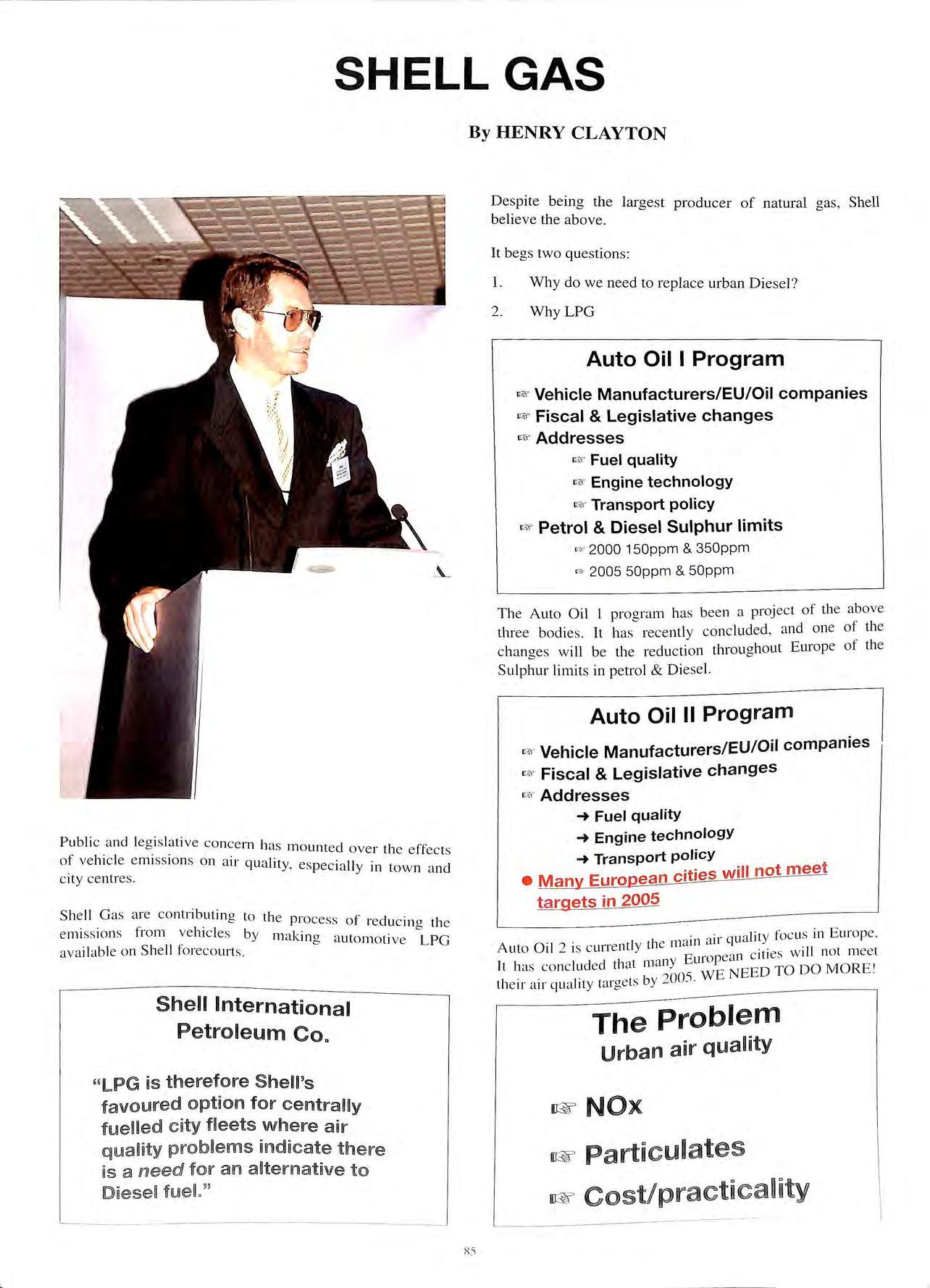
Publi c a nd leg is lative co nce rn has m o unt e d over the effec ts of vehicl e e mi ss io ns o n a ir qu ality, e spe ci a ll y in to wn a nd c ity ce ntres
Sh e ll G as a re co ntri butin g to th e process o f . cl · 1 Ie uc mg t l e e m1 ss 1on s fr o m ve hicl es by m akin g a ut o mo ti ve LP G ava il abl e o n Sh e ll fo re co urt s. Sh e ll Internati o n a l
le um C o . '' L PG us t h e refore Shell's fa vo lUlired optio n f o r ci t y wh e ire a nir nff1l d nc: ate th em us a mee d! foir an t o fl\JJe t ,,
By HENRY CLAYTON
Despite being the largest producer of natural gas , Shell believe the above.
It begs two questions:
Why do we need to replace urban Diesel ?
Why LPG
Auto Oil I Program
Vehicle Manufacturers/EU/Oil companies
Fiscal & Legislative changes
Addresses
Fuel quality
Engine technology
Transport policy
Petrol & Diesel Sulphur limits
2000 150ppm & 350ppm
' 2005 50ppm & 50ppm Th e Auto Oil I pro g ram h as bee n a proj ec t of th e ab ove three bodie s It ha s re cently concluded , and one of th e chancre s will be the reduction throu ghout Europe of th e b Sulphur limits in petrol & Diese l.
Auto Oil II Program
Vehicle Manufacturers/EU/Oil companies
Fiscal & Legislative changes
Fuel quality
Engine technology
Transport policy
Many European cities will not meet targets in 2005
air qu a lit y foc us in Europ e. Auto Oil 2 is c urre ntl y th e mcun c c i .t ies w ill no t mee t l y Euro pea n
has co nc lud ed t iat mdn NEED TO DO M O RE ' 1 1 ts by 7005. WE t i e 1r a ir qu a 1ty tmge
SHELL GAS
---·
Petro
l.
2.
i&
I&
i&
i&
i&
i&
I&
'"'
"
•F
=
•F
-+
-+
-+
•
.
Addresses
.
It
HB&
HB&
The Probl e m Urban a ir quality
Particulates
cost/practicality
The main air quality issues are related to the above two emissions , NOx and Particulates.
Proven
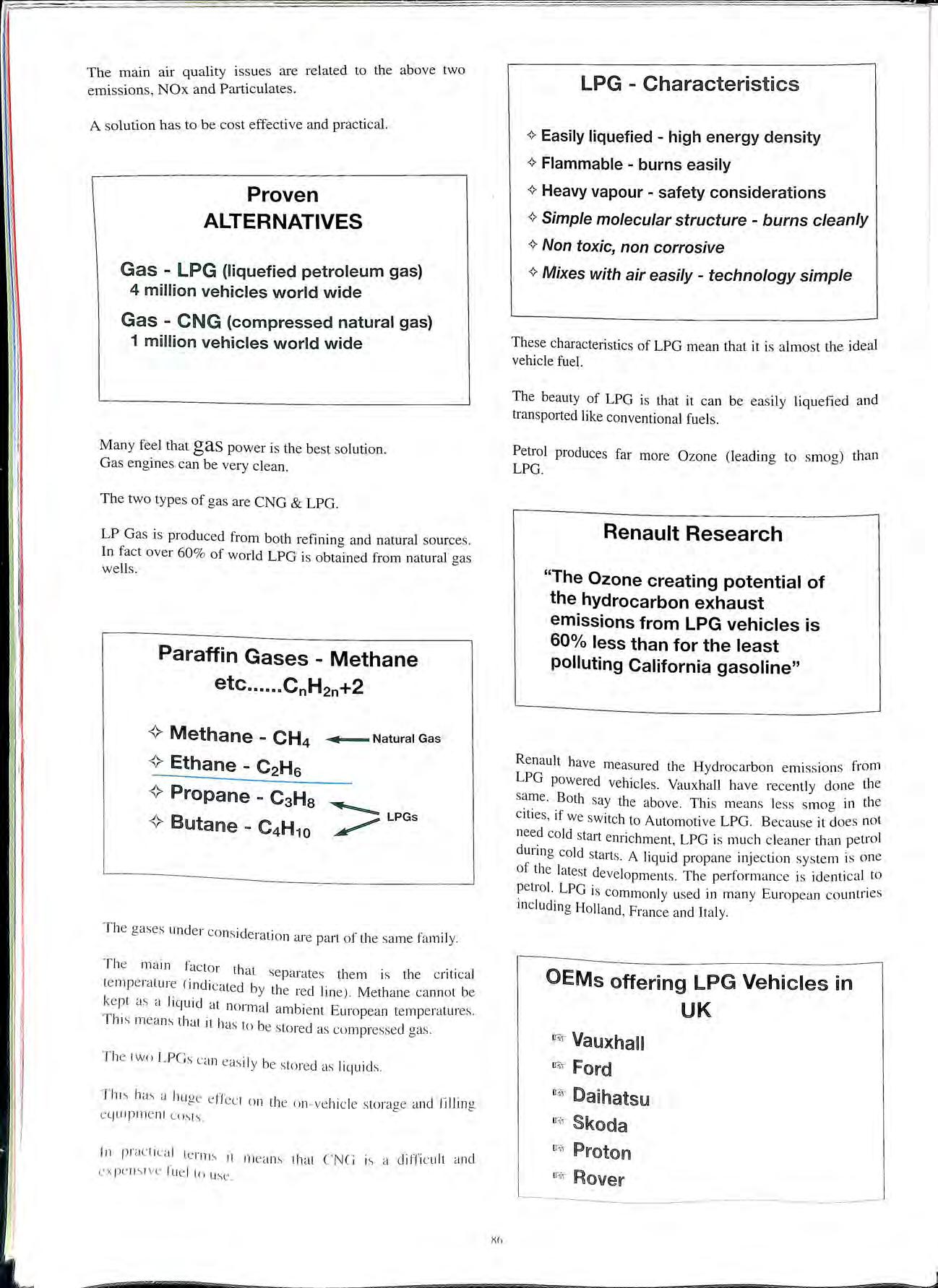
Charac t eris t ics
Heavy vapour - safety considerations
These characteristics of LPG mean that it is almost the ideal vehicle fuel.
The beauty of LPG is that it can be easily liquefied and transported like conventional fuels.
Petrol produces far more Ozone (leading to smog) than LPG.
Renault Research
Ren a ult have mea sured the Hydroc a rbon em1s s1ons from LPG powered vehicles Vauxhall have recently clone the sa me Both say the above. Thi s means less smog in the cities , if we sw itch to Automotive LPG B eca use it doe s not need cold start enrichment , LPG is much cleaner th a n petrol during cold starts. A liquid propane injec tion sys tem is one of the late st developments. The performan ce is ide nti c al to petrol. LPG is commonly used in many European countries mcluding Holland , France and Italy.
i I ;>
A solution has to be cost effective and practical.
ALTERNATIVES Gas - LPG (liquefied petroleum gas) 4 milli on vehicles world wide Gas - CNG (compressed natural gas) 1 million v e hi c les world wide
Paraffin Gases - Methane etc ...... CnH 2 n+2 <> Methane - CH 4 ...,_. Natural Gas <> Ethane -C 2 H 6 T he gases under co ns ideration a re part of th e sa me fa mil y T
ma
facto r that se parates them is the c ritic al te mp e ratu re (i ndi cated by the red lin e) M eth a ne ca nn o t be ke pt as a li q uid at no rm a l ambient E urop ean te
. Th
mea ns tha t it has to be sto red as co
d gas Th
ca n eas i Iy be s to red as Iiquicl s hw., a hug e ef fec t o n th e on ve hicl e storage
fi
nt
s ts
rm s it me
Xh
Many feel that gas power is the best solution. Gas engines can be very clean. The two ty pes of gas are CNG & LPG. LP G as is produced from both refining and natural sources In fact over 60 % of world LPG is obtained from natural gas wells.
he
in
mperatures
is
mpresse
e two LPGs
a nd
llin g eljU 1pm e
co
In practi ca l te
an s that CNG is a difficu lt and fue l lo use
<>
<>
<>
<>
<>
LPG -
<> Easily liquefied - high energy density
Flammable - burns easily
Simple molecular structure burns cleanly
Non toxic, non corrosive
Mixes with air easily technology simple
"The Ozone creating potential of the hydrocarbon exhaust emissions from LPG vehicles is 60% less than for the least polluting California gasoline"
OEMs offering LPG Vehicles in UK iBr Vauxhall ()$-" Daihatsu u::.;,- Skoda u-;;, Pmtoll1l IV?> Rover
The future for Automotive LPG is with OEM production of vehicles. The first in the field are the manufacturers above.
Shell Gas have been active in persuading fleets to run on gas
DHL runs 6 Transits in central London. The Shell Gas skid filling point allows them fill with gas before large numbers of Shell Retail sites are up and running.
Special characteristics of LPG filling
::u-e setting an industry leading example by announcing plans to set up 200 sites within the next two years or so This is the first at Dover. Dutch and French motorists are glad to find a ready supply of gas waiting for them just near the ferry port.
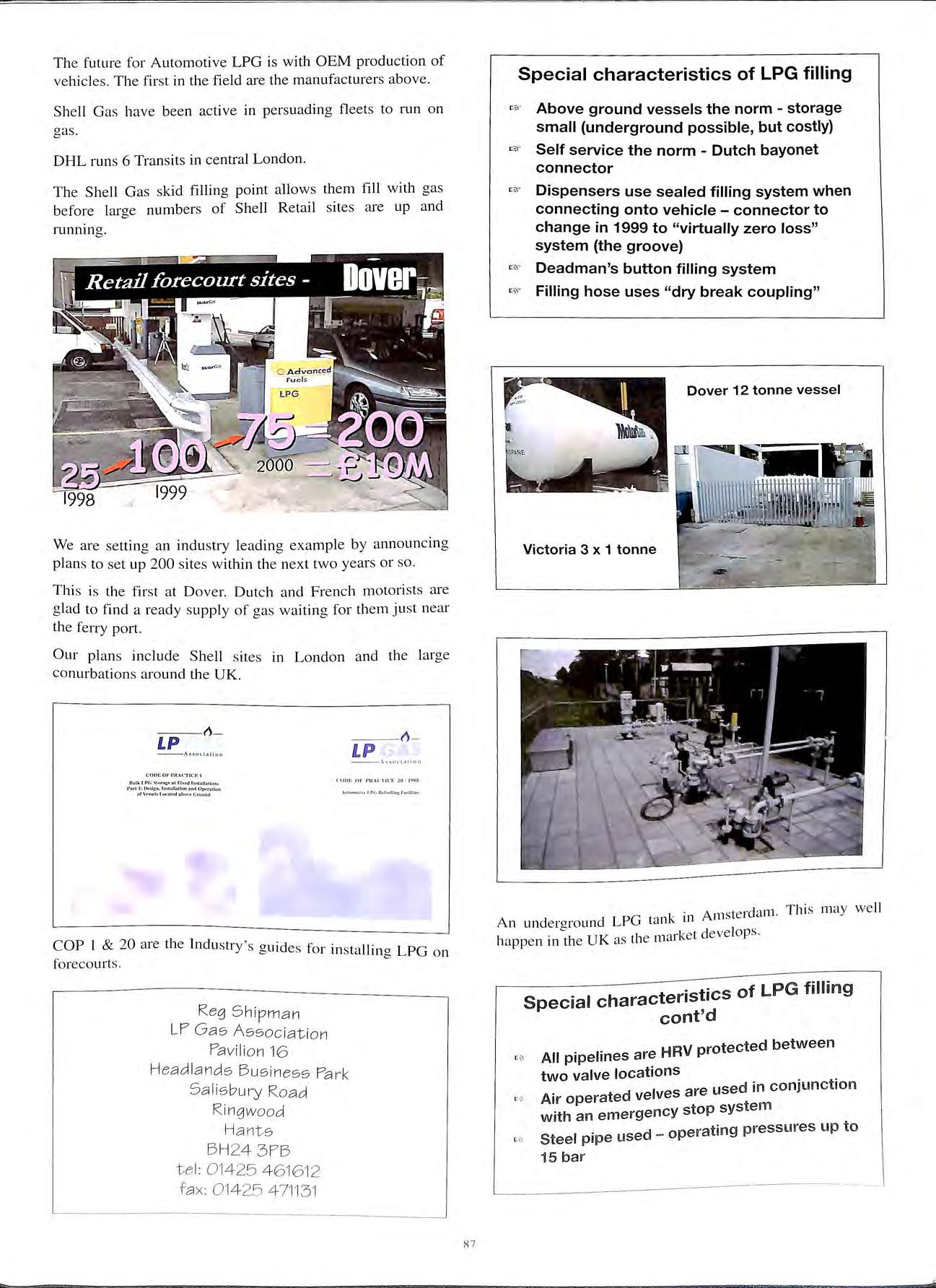
11 LP --/\ H oci 1!i o n f' rt Ov<nlll<lfl or v....,...i. 1 1o<1Al•<,,rCtound 11 LP COP I & 20 are the Industry' s guides for installing LPG on forecourt s . Reg Shipman LP Gas As s ociation Pavili o n 16 Headla nds Bus iness Park Sa li sbury Road Ringwood Hants B H2 4 3PB t el: 0 1425 4 6'16 12 fa x: 0 142 5 4 7'11 3 1 8 7
We
Our plans include Shell sites in London and the large conurbations around the UK.
=
=
"""
""'"
=
uses
coupling" Dover
Victoria 3 x 1 tonne d 1 Thj s may well An underaround LPG ta nk in Amster an · "" ·k t dev elops. happen 111 the UK as the m::u e
characteristics of LPG filling cont'd . . HRV protected between All prpehnes are two valve locations . . I s are used in con1unct1on Air operated ve ve with an emergency sto p syste m d o p erati n g p ressures u p t o Steel pi p e use 15 bar
Above ground vessels the norm storage small (underground possible, but costly)
Self service the norm Dutch bayonet connector
Dispensers use sealed filling system when connecting onto vehicle connector to change in 1999 to "virtually zero loss" system (the groove)
Deadman's button filling system
Filling hose
"dry break
12 tonne vessel
Special
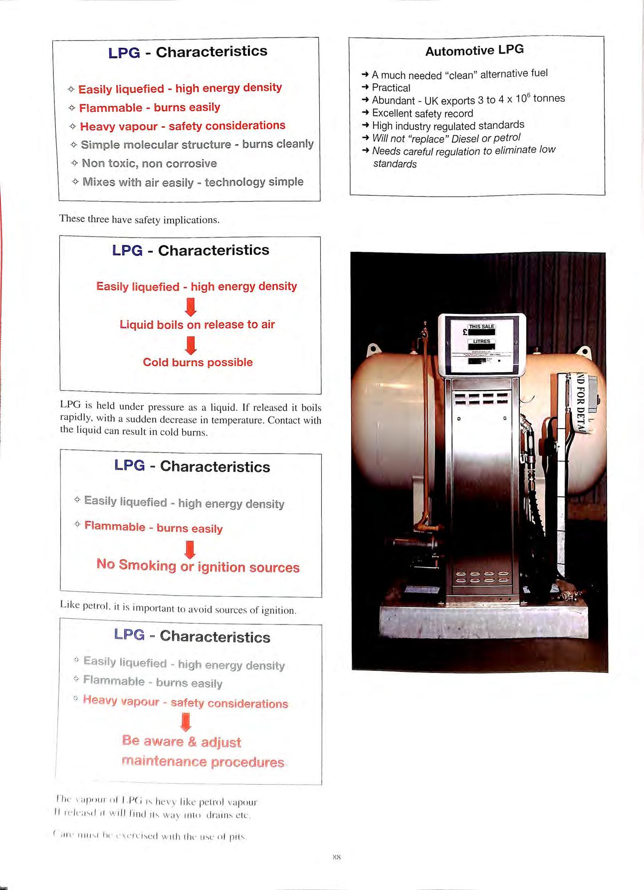
LPG Characteristics <> Easily liquefied high energy density <> Flammable burns easily <> H eavy vapour safety considerations <> Simple molecular structure burns cleanly <> Non tox ic , no n corrosive <> Mixes with air easily - technology simple These three have safe ty implic ation s. LPG Characteristics Eas ily liquefi ed hi g h energy density ' liquid boils o n release to air ' Cold burns possible LPG is he ld und er pressure as a liquid If re leased it boil s rapid ly, w ith a sudd en decre ase in temperature Co ntact with th e liqui d ca n re s ult in co ld burn s LPG - Characteristics <> !Easily liq uefied high ener gy density <> Flammable bums easily ' No Smolkung or ignition sources Like pe trol. it is important to avo id sou rces of ig ni tio n llPG = Characte ri stic s °' Easily liquefied high energy density <> IFiammalble burns easnly ;; Heavy vapour safety considerations l Be aware & adjust maintena1111ce procediures flw <I Jl!lll f" n f f,P(; hevy li ke pe trol vapo ur If 11 w ill find ih w a y int() cJra im e lc ( di\ ' hl' l"\L' f"L l \<.; d w ith lhL' o l pi t;, Automotive LPG -+ A much needed "clean" alternative fuel -+ Practical -+ Abundant UK exports 3 to 4 x 10⁶ tonnes -+ Excellent safety record -+ High industry regulated standards -+ Will not "replace" Diesel or petrol -+ Needs careful regulation to eliminate low standards xx
PROPER PLANNING & PRIORITISATION FOR ECONOMICAL BURIED PETROL STORAGE TANK MANAGEMENT PROGRAMS
By: Michael K. Baach, Executive Vice President Corrpro Companies, Inc., Medina, Ohio USA
INTRODUCTION
The high cost of a cotTosion failure and the consequential release of petrol into the environment is demonstrated by the recent incident near the Liverpool Street Underground Station. Reports are that sometime in April 1998, a release of approximately 37,000 litres of petrol was discovered. The owner initiated clean up immediately upon discovery of the leak. Costs for this remediation have been significant and continue as of this writing in July. This cost was probably not only avoidable, the clean up pounds would have been much better spent on a proactive program of leak prevention thus providing the operator with a return on his investment.
The Health and Safety Executive and Environment Agency will soon publish rules governing the operation of buried petrol storage tanks. Operators will then face the challenge of how to most effectively, yet economically, address their existing storage tanks.
For both new and existing facilities, minimizing liability at reduced costs is the key element of a prudent tank management program. Although the regulatory requirements must be satisfied, the paramount issue is to prevent leaks in order to minimize exposure to public liability.
The methodology presented in this paper has been demonstrated to economically achieve these very important goals.
OVERVIEW
the options to replace or modify an ex1st111g buned .storage tank system. two important issues should be exammed. if the operator does not require the storage tank system, It should be properly removed or closed. Secondly, storage tank replacement exposes the owner and operator to additional liabilities in the first few years of operation. The probability of a release is increased during this initial time period due to backfill settlement loose connections. Prop.er .installation and will reduce. but will not ehmmate. this exposure. For facilities that are to remain in operation. modification of the buried tanks. pipcworks and fittings through the application of cathodic protection is an effective and economical means to provide leak prevention. (See related article in 1997 Conference Edition of The Bulletin. Vol. 36 No. I).
Tank operators throughout the world have experienced what seemed to he a perplexing phenomenon 111 implementing their !<Ink management programs. Com·entional wisdom suggested that a managL'lllent plan
needed to address tanks in descending order of age, oldest first. This paradigm proved most costly and unproductive for one such operator of more than 2,000 petrol stations in the United States. In his replacement program, the operator was finding that many tanks that were 20 or more years old looked brand new when exhumed, while tanks only 5 or 6 years old were already experiencing leaks. Not only was the "oldest first" approach to this operator's program ineffective at minimizing liability, it failed to take advantage of the highly economical opportunity to modify rather than replace structurally sound tanks, regardless of their age.
The essential first step in planning for a tank management program is to establish the expected leak-free life of the existing tank population. When this is established, replacements can be planned, budgets established, and leak prevention measures taken where appropriate.
PRIORITISATION METHODOLOGY: "The Key to a Successful Program"
Wan-en Rooers Associates (WRA) developed the procedures for 0defining site specific leak probabilities for the American Petroleum Institute (API) in 1979. At that time, the API initiated a study of the problem of h 1s of the major ml tanks 111 order to address t e conceu · leaks frequently and compames who were expenencmg . . . I d. 1· 1 a11d clean-up costs. mcurnng substantia reme 1a 101
·1 companies in the U.S. Althm1oh at that time the n1<1J01 °1 tl 0 d" tl ir t"lllk populations. 1ey were committed to upgra mg 1e ' f .· .· · .· 0 d d ome means o p11011t1sme recogmzed that they nee e s d. 0 rourams are . . B stich upo1 a 1110 P e their act10ns. ecause · 0 •• _. 1 • 0 they are necessa11 y cl expensive and time consummc-. , t tl . t , " Moreover. it was la mult1-yeai unde1 takmc-· · descendm cr order h . h . I ed replacement in cprograms w 1c 111vo v , f such a program . . d t In the c0t11 st: o , , oi .ige we1e 111.l equa e. j \Vere sound and t h t lllks removet · · fifty-five percent 0 t e ' ,. .· a a ·r were kaklllc-· many tanks which were youn°e
PI ported the conclusion that Data gathered by the A Le·iks were found in I l . o, w·1s inett1c1ent. ' . 1ep acement 1y .ic-e '· t. · ist·tlhtion. and tanks . . , ... '" ·J .. three years a te1 II . ' , sysk ms ,1s e ,11 Y ,1s 1 'tl "llld tound to be 1l w >re t'XL<l\o.I t: over thirty live years o ( e -1·. ··t utcd over tune. leaking was randomly L 1st11 1
I ·st•"I that WRA statistical\\ ( , I tl API rcqt t:. ,, ·. onsequent v. 1e · 1 ,·tllL'L'tL'd ti1l' rail' ut • 1 • ·sst's wh1c 1 L'\ aluate the ph) s1ca pioLt:. · · 1·., ·t I t I , At1cnt1on was L11 LL L'L 11 t k' detenorat1on ol tank systL ms. 1 l ·ion \Vh1ch 1s till' d1l111111ant L·au-.L' problem ol externa nn 11 s · , t' I ··t·-'L'' t·111k S\Stcms. ol la1 ure ol unprntec Ll ·', '
XlJ
Processes of Corrosion
Physical examination of exhumed tanks revealed that the process of external corrosion proceeds in two distinct ways, with important consequences for tank life. The factor· which distinguishes these two processes is the presence or absence of anomalies on the tank surface or in the backfill.
The first of these two processes is uniform corrosion. This occurs when no anomalies exist on the tank surface, or in the backfill in immediate contact with the tank. Corrosion thereby occurs uniformly over the tank surface, without pitting until the corrosion cells are passivated, resulting in very slow rates of corrosion. Tanks with uniform corrosion will typically outlast the useful life of the facility at which they are installed. This condition exists at approximately twenty-three percent of all steel tank systems.
The second of these two processes is pitting corrosion. This occurs when anomalies such as coating flaws, abrasion or mill scale occur on the tank surface, or exist in the backfill in direct contact with the tanks. In this instance, pitting corrosion differs from uniform corrosion in that points of concentrated corrosion occur on the tank surface. Pitting corrosion is not uniform and allows high rates of corrosion to continue, until perforation of the tank ultimately results. This condition is noted in approximately 77 percent of the systems evaluated.
The physical processes which cause corrosion are well known. They are electrochemical in nature, can be chemically or biologically induced, or can be the result of an externally generated DC current source. The most important soil variables in determining the rate of chemically or biologically induced corrosion are electrical resistivity, acidity, moisture content, chloride concentration and sulfide concentration. The result of WRA's work the precise mathematical nature of the way in which the corrosion process occurs. Once the rate of corrosion is established, then the Corrpro/WRA Mean Time to Corrosion <MTCF®> could be determined.
Confirmation of Findings
To support the investigation, data was gathered on tank leak incidents by the API in the United States and the Petroleum Association for the Protection of the Canadian Environment <PACE). In all, data on tank leak status and the values of the variables noted above were collected at over 2JJOO facilities. A preliminary review of the data, however. showed that none of the supposedly causative vanahles. taken independently, bore any immediate obvious relationship lo the age at which leaks were observed.
The model which was developed from this initial data resuJred Ill a procedure which predicted age to leak within l 'i years. when the values of the relevant variables at a site ;in· known Jn addition. the prnhahility of leak at any tank :iµc L ouJd I hen he established. <)II h"'-'lf Ill' 111
I JIJlfli!IJJl''· llJl
data gathering and analysis. While the original data was drawn from a very limited geographical area, these later investigations disclosed that there were important geographical effects to be accounted for. In addition, the effect of stray DC currents was incorporated into the model. This allowed refinements in the estimation of the Mean Time to Corrosion Failure (MTCF®) that reduced the estimated error to 1.5 years when regional models were applied. The data base now used in this study includes test results from 70,000 tanks at 22,000 locations.
The Corrpro/WRA MTCF® program utilizes the precise data gathering procedures and highly refined statistical model as described above to provide storage tank operators with a unique, critical element necessary to properly plan, program and budget their tank management program. By ® properly employing the site specific results of the MTCF analysis, management action can be directed toward the highest risk locations to the extent that resources will permit, with the assurance that those resources will be optimally applied.
TANK MANAGEMENT PROGRAM
Although implementation of the site specific plan is a specific part of the program, there are various action items that can and should be implemented during each phase. These are specifically identified in the following descriptions.
General Planning
The General Planning Phase of the program consists of:
• Definition of Facilities
• Confirmation of Need
• Review of Operational Procedures
• Identification of Historical Problems
• Preparation of an Aggregate Budget
The first element is to define the population of tank systems, their material of construction, age, operational history, etc.
Confirmation of Need for the tank systems is an obvious element of the planning process as discussed above.
The Operational Procedures should be reviewed in the important areas of deliveries. dispensing. metre calihration, inventory control, emergency response and financial responsibility. Areas where improvements are prudent should be identified.
Historical Problems and data related to such things as releases, tightness tests, tank and piping replacements or expansion should also he identified.
1·on1rollecl experiments with Corrpro pnmillcd t'Xlcnsive refinements in both
The Preparation of an Aggregate Budget for storage tank system modifications. replacements and closure nr removal should then be prepared to facilitate allocating the rc4uired financial resources. These hudgets can he developed hy
:\ I' I I
l)()
comparison to ex1st111g regional storage tank system data bases. It has been determined that the most economical approach to tank management is a program consisting of budgeted costs for:
• Site Specific Corrosion Survey (MTCF®)
• Precision Inventory Management
• Selective Removal or Permanent Closures
• Remedial Measures
• Selective Tank Replacement
• Selective Modification to New Standards
Following completion of the General Planning Phase of the program, certain actions can be implemented concurrently with the Site Investigation Phase. These may include improvements in operating procedures such as emergency response plans and inventory control; closure or removal of unnecessary facilities; and enhancement of the financial position through insurance, risk reduction groups, surety bonds, etc.
Site Investigation Phase
Site specific investigations are the next Phase of the modification program to address:
• Analysis of Inventory Records
• Identification of Applicable Regulations
• Assessment of Environmental Risks
• Identification of Existing Contamination
• Collection of Data for MTCF® & Modification Designs
• Prioritisation of Specific Sites
Inventory should be statistically analysed to define any consistent trends. This analysis will also reveal deficient. operating (e.g. tank gauging, sales effors, pilferage) while satisfying the release detection requirements.
Applicable Regulations at the national and local levels must be identified for inclusion in the tank management plan.
By visiting the site, Environmental Risks can be assessed through area observations related to water supplies, utilities and puhlic huildings: Existing Contamination can be identified through borings and testing for soil vapours and chemicals: Data for Modification Designs can be measured and recorded at the site: and in the case of steel tanks. data for Prioritisation can he collected through measurements or the electrical and chemical soil properties. This data is then run on a computer model to calculate the Mean Time to Corrosion Failure !MTCF®1. and the probahility of a leak now and in futurt' year-;. Each site is placed in one or three cate}lorics according. to Probable Rekase. High Risk and Ri"k. Within each categmy. the lllllllL'riL·al \ alllL'" provide the hasi-. for prioritisation.
hillov. ing n1111pktion or tilt' Site Im c"tigaliun Pha-.,c ol
the program, additional testing to confirm system tightness and detailed testing to define, where necessary, the extent of contamination can be implemented.
Specific Plan Development Phase
Site Specific Plans are then developed based upon the results of the Site Investigations. This Phase of the program includes planning for:
• Corrective Action
• Replacement/Repair
• Spill/Overfill Prevention
• Release Detection
• Corrosion Protection
Detailed environmental assessments, selectively performed where the Site Investigation reveals contamination, provides the basis for development of specific Corrective Action plans. Locations where tanks require Replacement/Repair are defined during the confimmtion of tightness. Replacement systems must be <lesioned in accordance with the federal and local e regulations. The other elements of the modification plan (Spill/Overfill Prevention, Release Detection and Corrosion Protection) are then specifically developed for each site as described earlier.
Implementation Phase
Following development of the site specific requirements, the plans must be implemented. Although obvious, care should be exercised during implementation to address certain areas:
• Specifications
• Contractor Selection
• Construction Staging and Coordination
• Inspection
• System Commissioning
The Implementation Phase of the program is the area where the storage tank system operator reaps the economic benefits of good planning and site specific investigations. Considerable savings will be obtained by preparing good specifications and selecting competent contractors. Where cathodic protection is part of the modification plan. the design and specifications should be performed by a Corrosion Expert. It may be that a single contractor is capable of performing all work at a given site. If multiple contractors are required. all construction work should be wl'll courdinated to avoid duplication of drilling. pavcml'nt repair. etc. Although this too is ob\ inu-.. time" lnspel'lion and Systl'm Commissioning arc not gi\L'n prnpn allL'lllinn. Thl' 01wrator must ensurl' that Ill' &L'ls \\hat Ill' pay.., for.
The UjKTator l·an rl'dtll'L' hi-., liahilit\ b\ an 1mkpc11dcn1 firm tor !1hj1L'L'l11111 and \, "ll'lll ( '111111rn..,-.i1111i11g Thi" approad1 ''ill l'll"lli'' 11ni 11,. 1
<ii
installation of specified components , certification of system d s ubrru·ss1·on of as -built records In later years, te s ting an · · d the inde pendent engineer can also a udit an record keeping procedures to required for further li ability red uction and regulat01y compliance.
Monitoring and Records Phase
Prudent bu siness practice dictates that certain be maintaine d at the site or are readily ava ilable for review b y enforcement age nci es. The se include:
• R e lease Detection Monitorin g
• Con-osion Protection Monitoring
• Closure Records
• All Repair Record s
• A ll Modification Record s
When establishin g the M o nitorin g and Records progra m , areas other than the regulation s mu s t a lso be addre ssed :
• P er so nnel Training
• Data Collection/Tran smi ss ion
• D ata Management
Th e eco nomi c coll ec tion of goo d data by train ed peop le is es se nti a l. For operators of la rge numbers of storage tank s ys te m s, co mputeri ze d dat a co ll ec tion , tran s mi ss ion and management is often the m os t econom ic a pproach These s ys te m s provide th e additional advantage of qui ckly ge neratin g e xcepti o n re po rt s, gra phi c s and hi s tori cal trend s
ECONOMICS
The s torage tank s y s tem modification pro gra m he re in de sc rib ed in co rp o ra tes s ite s pec ifi c asses s ment, prioriti s at io n a nd impl e m e nt at io n in c ludin g:
• S ite S ur vey
• Preci s ion In ve nt o ry Management
• Rem e di a l M eas ure s
• Se lect i ve Re m ova l/C los ure
• S e lect ive Re pl ace me nt
• Se le ct ive Modification s
T he e co no mi c be ne fit o f thi s ap p roa c h is bes t illu s tr ated by an a c tu a l c a se hi s tory in t he U nite d S tate s in vo lv in g 14 17 tank s at 3 74 s ites. Fo r thi s a na lys is , it wa s ass um ed lh <tt th e pm g ram w o ul d e x te nd o ve r I 0 year s at a 5 %, infl a tion rat e ancl I ()'fr di sc ount rate. The present va lu es of a lt e rnati ve approa c he s in c o s t pe r s ite a ncl as a pe rce nta ge o f th e c os t o f m ini mum c omp li a nce w ith the reg ul at io ns are -; ho w n 111 Fi g ure 5 T he -; a v in g s ov e r minimum comp li an c e w ith the reg ulati()n s is th e rdorc 59 °.4 by use of th e he re in prog ra m
SUMMARY
A properly planned modification program , as described in this paper, produce s the fo ll ow in g :
• The pote ntial for catastrophic liabilit y is minimi ze d
• Remediation costs are reduced due to the site s urveys
• Capital costs are reduced by savi n g good s ys te m s
• Management can acc urately plan and budge t th e program
Proper plannin g wi ll greatly impact th e cost of a n underground storage tank management progra m By prioriti sin g action s, timel y comp li ance with the reg ul a tion s ca n be ac hi eved whil e env ironmenta l li ab ilit y is g rea tly reduc ed throu gh leak prevention.
Owners and operators can modify th e ir ex ist in g underground stee l tank s and pipeworks at a fracti o n of the cost of replacement. By properly installing and m a intaining a cathodic protection system, s tructurally so und underground stee l tank s ca n be kept leak free. Since th e APEA/IP Draft Code of Practice for the Ope rati o n of Pe trol Station s allow for th e modification of und e rg round s tee l ta nk s w ith cathodic protec ti o n, o perators can g rea tl y be ne fit fr o m thi s econom ical alte rnativ e to tank re pl ace m e nt whi le assuring a safe , e nvironm e ntally protective pe trol s to rage operation.
This pap e r was prepared by Mr Micha e l K Baoch. Exe c utive Vi ce Pres ident of Cor rpro Companies. Inc.. the wo rld s· lead in g pro vid e r of co rro s ion c o n!rol ond mon i torin g technolo g ies. For more informalion Mr Bauch can be con. ta c!ed al Co rrp ro Companies. /11 c. , 1090 Enterpr ise Dri ve, Medina , Ohio 44256 330 723-5()8 2 (phone) , 3 30 72 3- 0244 (fo x ), or H'WW. c onpm.co11 1 (w e bsite) o r Cor rpro Europe, Adam Slreet Bmr e s/ ie ld Lane , Stock/on on Tee s , C lev e land TSIR 3 /-/Q Te l : 1642 6 14 106 , Fax. 16 42 614100.
"MTCF® is a trademark of Coi"rprn C ompanies, ][n c. , r egistered in t he U.S Patent a nd Trademark Office "

M H PARTNERSHIP SURVEYORS, PROJECT MANAGERS, ARCHITECTS 30 YEARS EXPERIENCE IN THE DESIGN, PLANNING, CONSTRUCTION AND COST CONTROL OF SERVICE STATIONS, SHOWROOMS AND WORKSHOPS THROUGHOUT THE COUNTRY FROM THE INSTALLATION OF A SINGLE TANK TO A COMPREHENSIVE DEVELOPMENT 3 Park Court, Pyrford Road, West Byfleet, Surrey KT 14 6SD Tel: 01932 352727 Fax: 01932 351545 email : mbhptshp@compuserve.com FORMERLY McCARTHY BAINBRIDGE PARTNERSHIP Worcester Electrical . Services Ltd N IC E I l: l' n i t :! 8 1111 /; l o \ tat c Sourh H (J r n' \'l<!r 1VR3 8. I P FORECOURT INSTALLATIONS T E L: 01905 28402 FAX: 01905 28410 A N D E lectrical Te s tin g LPG In s tallers tr' 'JJtt · 'JJtr' ·;:zitr• ·s 'tr' •t n:t • •t 'tri ·z 1ccs 'J 1rr: 'J 1tfU2J 1 a a 45 45 45 a q;D Fu ll range of re-sale approved and in-house models, for petrol, derv or lube oil. Range of dispensing speeds from 45LPM to 140LPM A ll equ ipment me ets the latest st andard s, is manufactured ou t of sta inl ess steel and built to last. For more information p lease contact PUMPT RONICS at Folgate Road, Nor th Wa lsha m, Norfo lk, NR28 OAJ. Tel: 01692 5006 40, Fax: 01692 406710.
safety Modern fusion equipment and recorded results provide the basis for integrated quality assurance from the manufacturer through to comprehensive on-si te documentation.
,I L ELGEF® Petrolockthe strong combination Tlhe economical system • High ly flexib le piping system for efficient installation • Fully developed modu lar system and integrated pipe fixing up to d63 mm fo r minimum assembly time •Appl ica ti o n-specific internal coating of t he p ip e s fo r high environmental co mp a t ib ility Ailld havnillg to make any c ompmm us es Olnl safety ELGEF Petrolock is the powerful combina tion of ELGEF Plus electrofusion fittings from Ge o rg Fischer and HALOCK laminated pipes fro m Halli ngplast AS. Geo rg Fischer· Piping Systems Ltd , C H 820 1 Sc ho ffh ouse n/ Sw itzerlon d Ph <x 1e +4 I 10152-63 I I 1 l 1, Fo x +4 l 10152 -63 1 28 00 e· rnoil: 1nfo@ r:..i 1i:..iing.geor-gfischer corn , Intern et : http:! / www p ip ing.geo rgfi sche r. co m GEORG FISCHER +GF+ • •
popnng systemso
Integrated
Excellence in
VEED J, -.t' WARNING. OTHER MANUFACTURERS' GAUGES COULD SERIOUSLY DAMAGE YOUR WEALTH. Official Warning from the Market Leaders in Tank Gauging. Z : • » 1· , .1=! .l\..;,;. I -. 1.·- 1

' I ,1 I j I j I I I , I I Drill S The New alternative providing drilled and threa ed access holes into En tri es For: e Gauging Systems e Vapour Recovery e Overfill Prevention e S ubmersible Pumps e Additional Lines The only system in co mm e rcial use comprehensively tested using therma l i ma gi n g technology by the health & safety laboratory Acknowledged as a saf e wo rkin g practi ce Ignition Safe Drilling An d Th reading 00 Drill Safe National ervice 44/0990 133111 Fax: 44/0990 133110

Tank Gauging and Leak D etection \ I I ' 40 60 / zo so'TankGuard' 2001 0/o e @I e lff. lf FI 'RQGAI tGF _.,... d.&!,.,,,&. I I TEST REFU. LIQUID FILLED AND DRY AIR PRESSURE LEAK DETECTION SYSTEMS FOR STEEL OR GRP DOUBLE SKIN TANKS. LEAK DETECTION SYSTEMS FOR DOUBLE CONTAINMENT PIPES, ACCESS CHAMBERS AND PUMP ISLAND SUMPS. "PROLEVEL " TANK GAUGING SYSTEM FOR UP TO 16 TANKS PC AND MODEM COMPATIBLE FOR LOCAL AND REMOTE MONITORING. " TANKGUARO ' LOW COST ELECTRONIC TANK GAUGING SYSTEM. " TANKMATE 160'' SELF-POWERED TANK GAUGE FOR DIESEL AND GAS OIL. INTERCEPTOR AND OIL SEPARATOR LEVEL ALARM SYSTEMS BS EN ISO 9001 QUALITY ASSURANCE. ALL SYSTEMS MEET RELEVANT SAFETY STANDARDS EEx ia /IC FOR ZONE 0 AND EEx ib /IC FOR ZONES 1 AND 2 . .. .. ....... ... ....... ..... .... ..... .. ...... .. .. .. Why not talk to the specia/ists:EUROGAUGE COMPANY LIMITED IMBERHORNE LANE , EAST GRINSTEAD , WEST SUSSEX RH19 1RF Tel: 01342 323641 Fax: 01342 315513 cfG site Qitality services for today's forecourt HIGH QUALITY RE-IMAGING OF PUMPS CANOPIES, SHOPS ' POLE SIGN ERECTION & MODIFICATION PLANNED IMAGE MAINTENANCE PROGRAMMES PUMPS & EQ UI PMENT - HAULAGE, STORAGE &DIS TRIB UTION Valley Road, Cinderford, G oucester GL 14 2NY Telephone: 0594 826364 Fax: 0594 822807

i i I I , I I/ I ! You deserve h the best, wysettle for less ... THE LEADER IN PETROLEUM TANK MANUFACTURE Including: • SUCTION PIPES • FILL PIPES • OVERFLOW PREVENTION • CHAMBERS • GROUND COVERS, and much more ... COOKSON AND ZINN LIMITED
Since pioneering the concept of the pre-engineered canopy back in the early 60's, continuous development has seen this simple form of weather protection evolve into the bright, sophisticated image projecting structure that ft is today
Over the years Conder has applied this same philosophy to other forecourt elements wrt:h the objective of improving qualrt:y whilst reducing construction time. These now include shop and car wash enclosures, factory prepared for rapid sfte assembly, pump island sunuunds wrt:h integral cradles and sumps and barriers to guard vulnerable fuel dispensing equipment
In protecting the environment, Conder's resolve has never faltered and is demonstrated by the most advanced range of light liquid separators, complete wrt:h coalescing filters, automatic closures and pollutant level alarms Add to this the GRP access chambers, silt traps and a first class repair and refurbishment service the forecourt couldn't be better protected.
CONDER FORECOURTS ABBOTIS BARTON HOUSE WORTHY ROAD WI N CHESTER, HAMPSHIRE S023 7SH TE&J 86351'1 FAX 0196 2 84 17 W
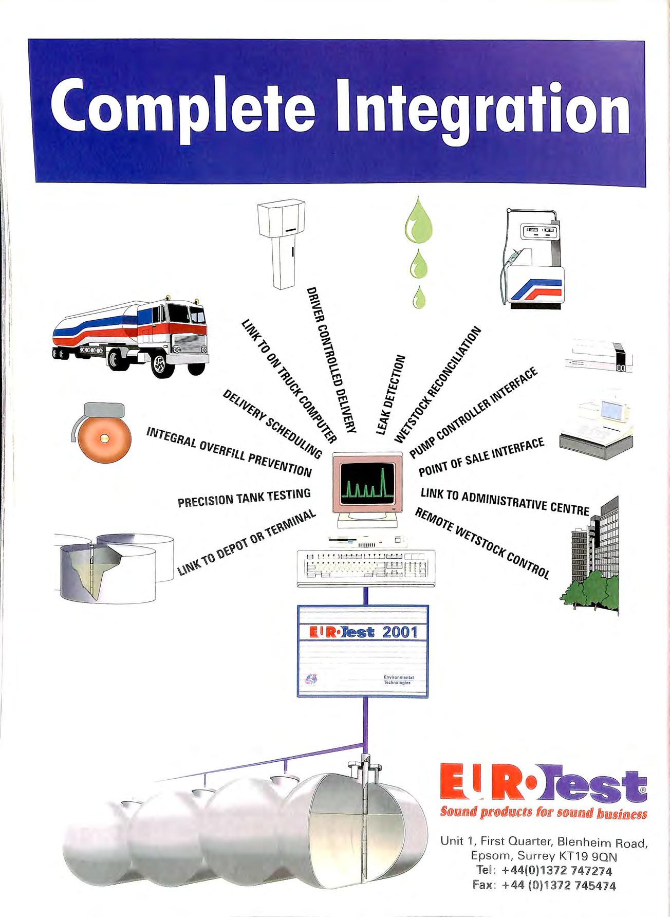
1 i . I ·I l i I I Complete Integration ( I R•Jest 2001 Envi1onmcntQI Tcdinotoo\c-3 S@und prodMtts f®r S@imd busfiJllless Unit 1, First Quarter, Blenheim Road, Epsom , Surrey KT19 9QN TeL +44(0)1372 141214 Fax : +44 (l0 )1312 745414

·p ·OLY-Tf:cH ·· Advanced Flexible Underground Piping System 0 Ease of Installation 0 Cost Effectiveness • Pressure or suction application • All fuel s Ut/ULC listed • Direct burial or secondary containment

.i I I I i I vc SPECIALIST ELECTRICAL ENGINEERS & CONTRACTORS TO THE PETROLEUM INDUSTRY • Close-circuit TV • Fire Alarms & Emergency Lighting • Planned Maintenance • Inspection & Testing • Forecourt Earthing Systems T he Eft'Ctrim l C1111/rm;lors' 1\ ssrlf.'ii1tio 11 HIG ISTERED MEMIJEll MEMBER OF A.P.E.A Nationa Inspection Counci for Electrical nslallalion Contracting HEAD OFFICE: PROJECT HOUSE ·THE DRIVE ·WORTHING ·WEST SUSSEX · BN11 5LL TEL: 01903 700321 BY TOTAL CONTAINMENT Low cost, flexible solutions for all fuel pipework PUIRfllElET fORlECOUR l • Most flexible pipework system • No underground joints • Suitable fo r alternative fuels • High flow rates • Competitive prices TOTAL CONTAiNIVIENT 520 London Road, West Thurrock, Grays, Essex RM20 3BE Tel 0 1708 863931 Ext 219 Fax 0 1708 864140 Sole UK PURFLEET FORECOURT SERVICES LTD Distributor

JRJ & NJf WJIJLJLIIAMS JLID SOUflH[lEIRN LID Building & Civil Engineering Contractors Contractors to the Petroleum Industry for over 2 5 years & Build/Tendered/Negotiated Management Car & Jet Wash Installations Tank Removal & Disposal Fuel Tank Installations to Quality Area of Operation BS EN ISO 9002 : 1994 1ZJ Audited Safety Procedures Client Driven RJ & NJ Williams Limited Te l: 01752 201300 Fax: 01752 201299 Williams Southern Limited Tel: 01635 871828 Fax: 01635 871784 0 0 u u • • I • • I CREATE LESS VAPOURLOSE LESS MONEY! Lincoln Partners Limited 1 Crossways House Enderby Road Blaby Leicester England LES 400 Tel: 0116 277 2700 Fax: 0116 277 2900 THIE FASTEST WAY T O :Put 2",3" & 4" threaded entries into tank lids Remove drop tubes Install & supply OPD's (including 4 " steel tubes) Remove any existing sockets d b HSE & all appropriate Safe accepte Y .. safety authorities . I II Cost effective Qu1c< S GOO D sENSIE TO USE ff MAKE BOR'l'EC Ltd 11 H d gham Ro ad,Wec he1·sfteld, Hud son H1 , e in 4EH Braintree, Essex CM7 Te l (0 I 37 1) 850921 Fax: (0 I 37 I) 8507 19 .l
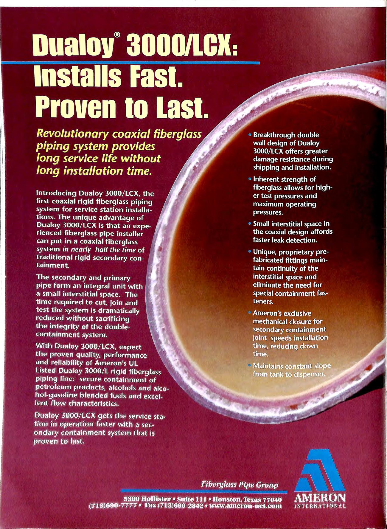

Environmental Engineering & Applied Science Extensive experience in undertaking specialist contaminated land remediation in the UK and Europe provides clients with tried and tested methods , applied by specialist staff, for dealing with polluted land and groundwater. • Site assessment on petroleum retail sites and industrial premises • Fully costed remedial design proposals • Execution of remedial works with minimum disruption • Confidential prompt and professional service SPECIALISTS IN CONTAMINATED LAND CONTRACTING Telluric Ltd, Meandros House, 54A Bute Street, Cardiff Bay, CF1 6AF Tel: 01222 303010 Fax: 01222 303011 Sofitam Pump Services Ltd • Forecourt & Commercial Pump Maintenance • Sole UK Approved Distributor of Beck Parts • Fuelling Equipment Stockists • Refurbished Equipment • New Forecourt Equipment Independent Pump Services Ltd • Pipework Installation • Tank Testing • Project Management SOFITAM Call us on (01273) 454831 Adur Baatyard, Old Shareham Raad, Shareham-by-Sea, West Sussex BN43 STA. Tel: (01273) 454831 Fax: (01273) 464863 With more than 20,000 installations throughout USA and Canada CONVAULT is th e premium above ground vaulted storage tank system available today. Now CONVAULT'S patented system is manufactured in th: United Kingdom and Ireland. This convenient, cost effe_ctive above ground fuel storage system is availabl e for use by Fire Autho1ities, Airports, Schools, Hospitals, Govt. Depts, Golf Courses , Marinas, P1ivate Business etc. A practical alte rnative for sto1ing petroleum based products and other flammable or hazardou s sub stances. CONVAULT'S U L 2085 Listed design is e ngineere•d___ --• for Safety, addressing strict 1r::t1..... ·I e nvironm ental and fire ._.....,.._...,..., _ safety requirem ents Capacity from 2000 16000 Litres. CAIL TODAY for details t • II I I I htpp://www.breton.co.uk SPECIALIST IN ALL TYPES OF PETROLEUM INSTALLATION CONTRACTING & MAINTENANCE. INDUSTRIAL I COMMERCIAL I AIR CONDITIONING. WITH OVER 20 YEARS EXPERIENCE 24 HR. 7 DAY SERVICE ALL YEAR CALL-OUT FACILITY. Breton Precast Ltd 122-126 Duncrue Street Belfast BT3 9AR Telephone: 01232 351711 fax: 01232 754053
TANK LI NING
TANK SERVICE UNITS
TAN!< CLIEAN !NG

Q
One Albion Street
Installation of retro-fit Double or Single Skin lining systems using the well proven "ADISA" systems used over a 20 year
...,i: TANK New tankage installed to suit client and Petroleum Officer local loc ation constru ction requirements TANK De p e n dab le se rvi ce n at ion wid e w it h f ull y approved and documented proced u res inc l ud i ng c o ld cutt in g, s l urry or foam infill ing a n d remova l o f so li d f ill ed ta nk s TANKUNiNG SYSTEM S ==== f /I I 1 J') /Vfc/ ( kFPRF.SFf\J !EU IN TI-If /J I< & IRELANO
Failsworth Manchester M35 OEG TEL: 0161 684 8534 FAX: 01616884101 period by major oil companies throughout Europe.
equipment has
All
been designed constructed to be granted UK and TUV European Petroleum Regulation approval for product uplift and transfer in conjunction with inflammable liquids belonging to all dangerous categories.
All works undertaken in strict compliance with HSE and Petroleum Regulations including "OCTEL" Leaded Gasolin e Tank Cl ean ing st andard and TuV approval.
Signs & Labels
extensive list of products, 1s the fac1lity_to manufacture a wide range of engraved signs for many Industries. With our controlled machines, including CAD fac1lit1es Y?U can now order your signs with the rest of your material.
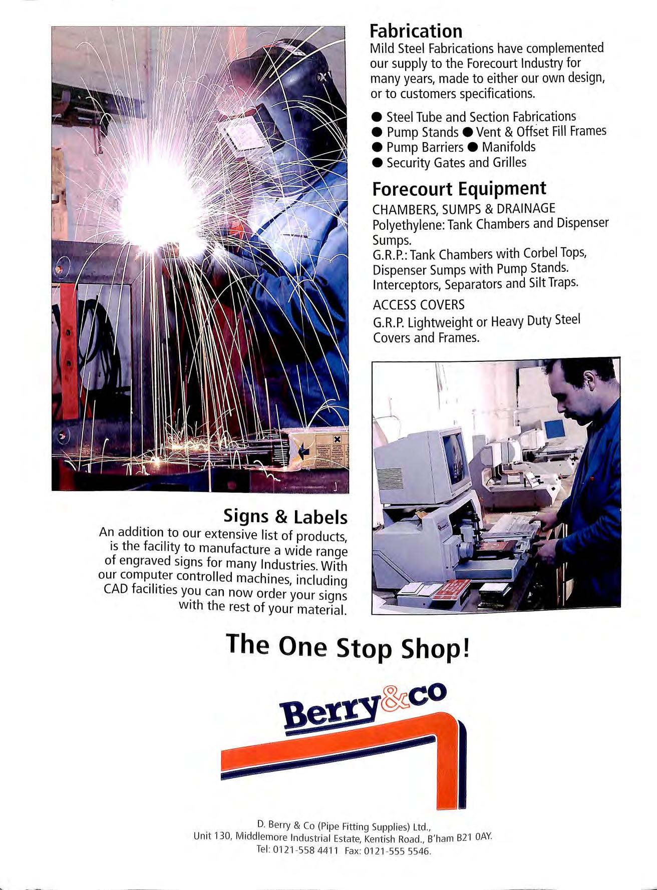
Fabrication Mild Steel Fabrications have complemented our supply to the Forecourt Industry for many years, made to either our own design, or to customers specifications. • Steel Tube and Section Fabrications • Pump Stands• Vent & Offset Fill Frames • Pump Barriers • Manifolds •Security Gates and Grilles Forecourt Equipment CHAMBERS, SUMPS & DRAINAGE Polyethylene: Tank Chambers and Dispenser Sumps. G.R.P.: Tank Chambers with Corbel Tops, Dispenser Sumps with Pump Stands. Interceptors, Separators and Silt Traps. ACCESS COVERS G.R.P. Lightweight or Heavy Duty Steel Covers and Frames. D. Berry & Co (Pipe Fitting Supplies) Ltd., Unit 130, M1ddlemore Industrial Estate, Kentish Road , B'ham 821 OAY Tel : 0121 558 4411 Fa><: 0121 555 5546
our

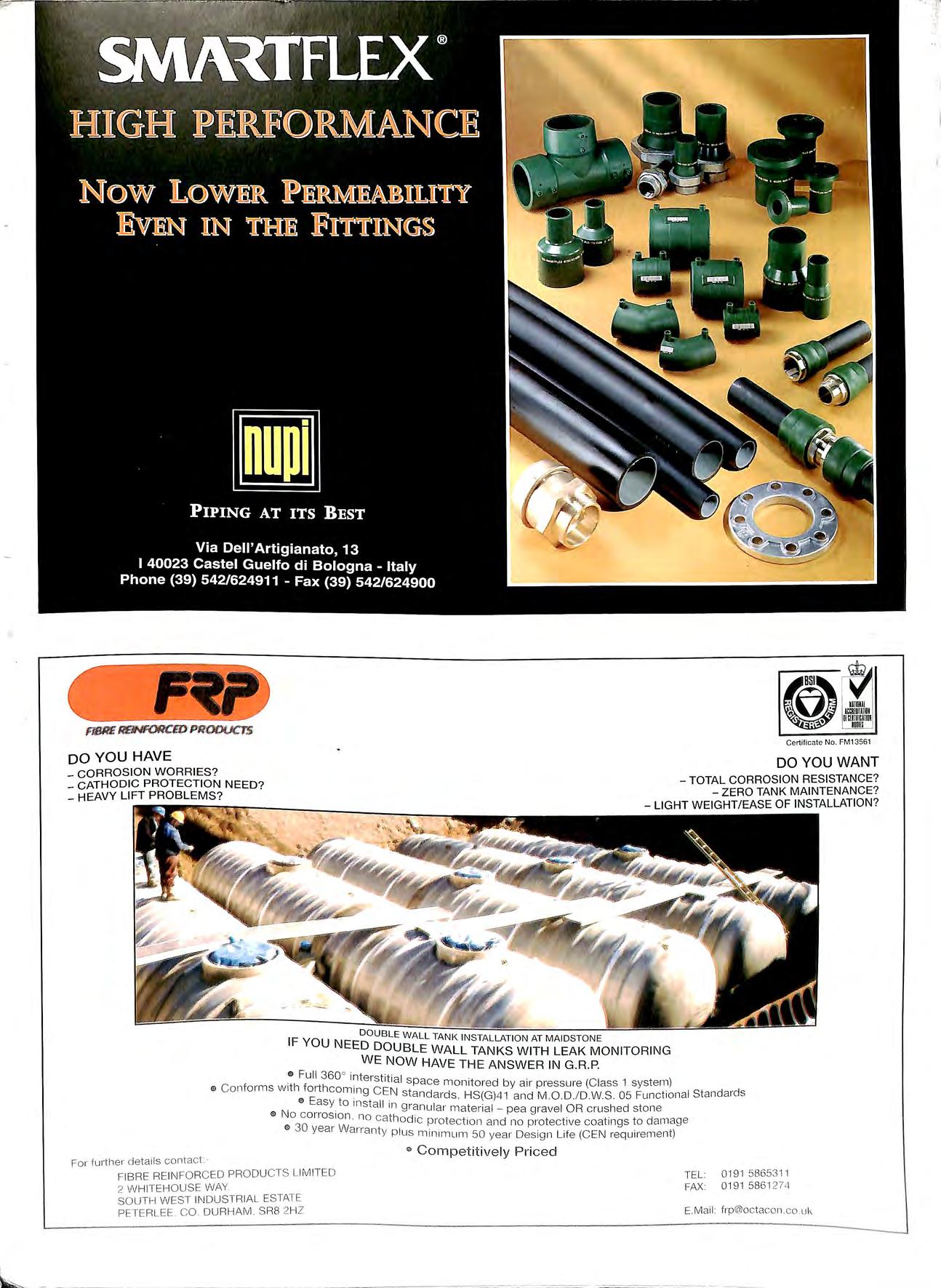
FfSllE R'fJIW{)RCW' PJlODUCTS, DO YOU HAVE CORROSION WORRIES? _ CATHODIC PROTECTION NEED? . u Certificate No. FM13561 DO YOU WANT TOTAL CORROSION RESISTANCE? ZERO TANK MAINTENANCE? _HEAVY LIFT PROBLEMS? LIGHT WEIGHT/ EASE OF INSTALLATION? DOUB LE WALL TANK INSTALLATION AT MAIDSTONE IF YOU NEED DOUBLE WALL TANKS WITH LEAK MONITORING WE NOW HAVE THE ANSWER IN G R.P. "' Full 360° interstitial space monitored by air p ressure (Class 1 system) "' Conforms wrth forthcom111g CEN standards, HS{G) 41 and M.O D./D.WS 05 Functional Standard s '" Easy to install in granular material pea g ravel OR crushed stone "' No corrosion no cathod ic protection and 110 protective coatings to damage 0 30 year Warranty p lus minimum 50 year Design Life (CEN requ irement) For furiher details contact · FIBRE REINFORCED PRODUCTS LIMITED 2 WHITEHOUSE WAY. SOUTH WEST INDUSTRIAL ESTATE PETERLEE .CO DURHAM SR8 2HZ " Competitively Priced TEL: 0191 58653 '11 FAX: 0191 5861 274 E. Mail: frp@octacon.co uk I
EMCD · WHEATON • environ A\n1ea"on C>PWFUELING COMPONENTS EUROPE B.V A DOVER RESOURCES COMPANY """'="'"" AND MANY MORE The Worlds Major Forecourt Products from the UK's Major Distributor D. Berry & Co (Pipe Fitting Supplies) Ltd., Unit 130, Middlemore Industrial Estate, Kentish Road, B' ham 82 1 OAY. Te l: 0121 558 4411 Fax: 01 21-555 5546. 0 . 9
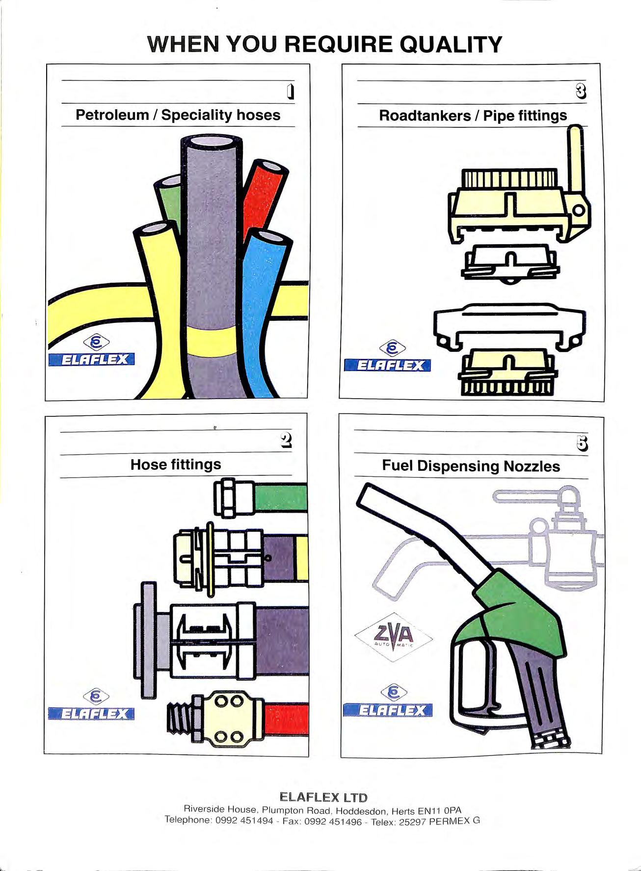
WHEN YOU REQUIRE QUALITY Petroleum I Speciality hoses Roadtankers I Pipe fittings Hose fittings Fuel Dispensing Nozzles 00 00 ELAFLEX LTD Ri vers ide House, Plumpton Road , Hoddesdon , Herts EN11 OPA Telephone : 0992 451494 Fax : 0992 451496 Tele x 25297 PERMEX G
UPP 16 years experience with over 5000 installations in SO countries worldwide.
Extra - lined pipe in a range of four sizes, giving zero permeability for zero expansion in fuel, suction and pressure lines. Optional unlined pipe for vent and vapour recovery lines.
Pressure rated to PN10 , easily exceeding pressure generated by submersible pumps.
Wide choice of diameters and lengths, including straight lengths and Une number, shift number, week and year of manufacture for full traceability and warranty.
Metre markings for ease of on-site measurement and quality control during ../ number.------------------
Secondary c , ·ned UPP fulfils every requirement for , mo · ing and recovery. Engineered for use with most leak dete ction systems. -------------------.