33 minute read
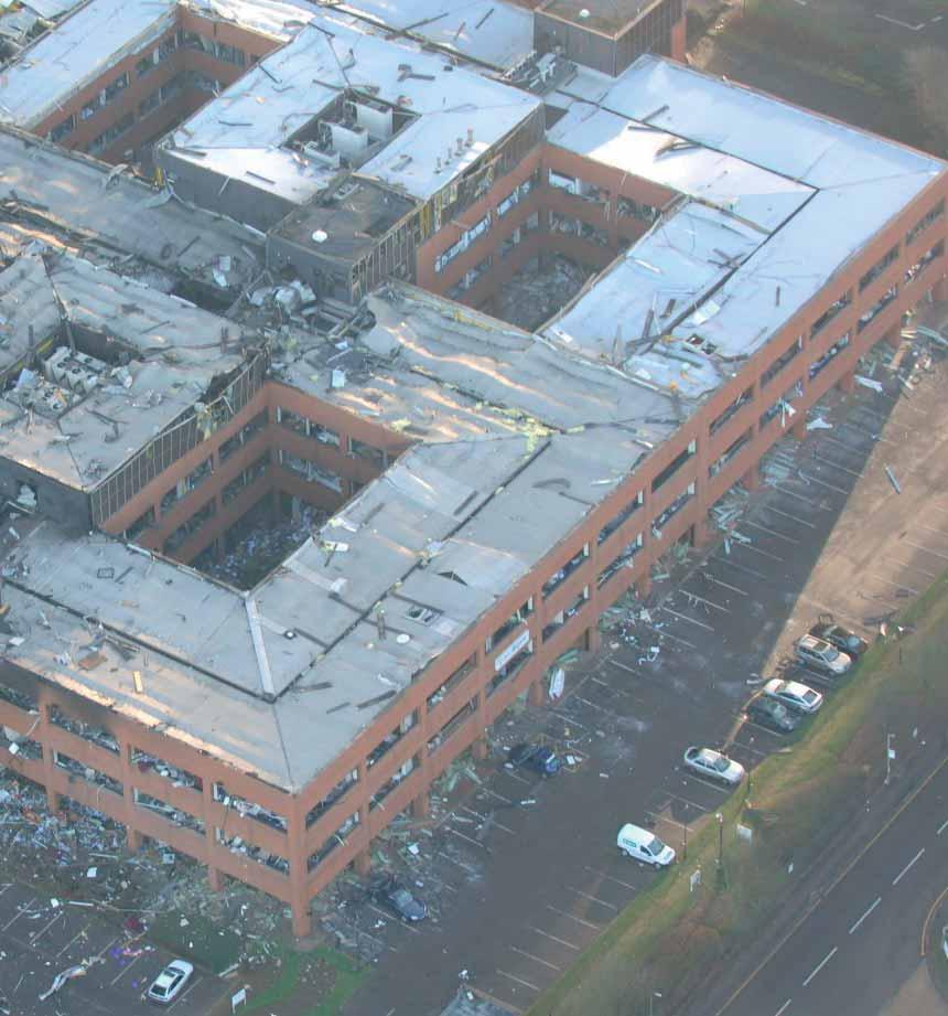
The Buncefield Terminal


safety systems, access and maintenance of pipelines. These regulations include provision for carrying out work on pipelines and dealing with any incidents or emergencies that may arise; this also includes giving due consideration to prevention of damage in the event of an accident
Other Incidents
Advertisement
Although many reports stated that this was the first fire at a UK oil terminal since the war this was not the case. On 1st April 1967 there was also a fire at the West London Terminal operated by Esso Petroleum. The official report issued on 6 September 1967 by the Chief Inspector of Explosives, Dr H K Black, reported on the consequences of the fire where three employees lost their lives and eleven were injured.
The company had installed new automated delivery systems for filling road tankers; this facility had been handed over the day before following commissioning by the installers. Problems encountered during the day led to the overfilling of road tankers with product spilling over the loading bays. The resulting fire and explosion caused loss of life, injury and extensive damage to the plant. The cause of ignition was thought likely to have been a road tanker engine starting up in preparation for driving out of the terminal.
The terminal was reopened with additional safety features which were adopted throughout the industry. The storage tanks on this occasion were not involved in the fire.
By Jane Mardell
I am writing this article this year to ensure that you are all clear as to what you need to do to be included into the 2007 Yearbook.
Some of you thought you would be included automatically into the 2006 Yearbook and were surprised when you did not see your contact details included.
As shown on the form your Registration Form must be returned to the APEAoffice for your details to be included by 1st April. This ensures that the information in the Yearbook is correct.
Even if you do not wish to advertise in the Yearbook, to be included in the Classified and Directory pages you should complete the form as follows: 1.Check your contact details are correct on the form and that these are the contact details that you wish to be included into the
Yearbook. If you wish to change them please amend the form. As an APEAmember you receive one free ‘Classified’entry.
2.Complete the Directory table
This contains a list of the
Directories that will be included in the Yearbook.
Please tick the box next to the Directory listing that is relevant for your business. You receive one free box. Additional boxes are charged @ £26.00 plus VAT. 3.If you wish to book advertising or have ticked additional ‘Directory’ boxes, complete the payment box at the bottom of the form.
4.Fax or post the form to the APEA office by 1st April 2006. This enables the production of the
Yearbook in time for Autumn delivery
I will then record the Registration forms received.
If you have any queries or need another form please do not hesitate to contact me at the APEAoffice on 01799 541816 or by email at admin@apea.org.uk
More innovations from D. Berry & Co Ltd Easy Riser tackles the P/V valve changeover problem
By Frank Hare
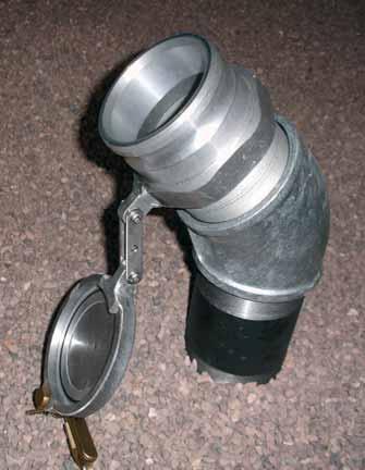
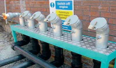
The new Working at Height regulations which came into force in April 2005 underline again, the importance of adopting safe working practices. With stage 1b vapour recovery systems now well established in the UK, there is a requirement for the annual inspection or change of the high level Pressure Vent valves. The practice of using a “cherry picker”, ladder or scaffolding to access these valves is commonplace, but none of these methods can guarantee the safety of the engineer undertaking the task. Using these methods also requires two men to complete the job, which could easily be carried out by a single operative if it wasn’t for the difficulties associated with working at height.
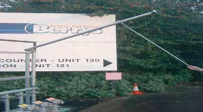
Berry’s have carefully researched this situation, and in light of recent accidents have found an answer to providing easy access to the valve. Their new “Easy Riser” has brought the commonsense approach of bringing the valve to the engineer instead of the other way round. The main difficulty they encountered was finding a suitable swivel joint that would retain the pressure in the line, whilst at the same time, allowing the upper section of the stage 1b vapour recovery unit to be lowered to a suitable working height.
Using their wide experience, Berry’s identified a suitable swivel joint. Substantial field tests of the completed unit were carried out and it was soon decided that the product could be declared a winner! By simply unlocking the riser pipe and lowering it to an acceptable working height the job can now safely be carried out by one man instead of two.
With this device in place it will no longer be necessary for engineers to be
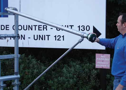
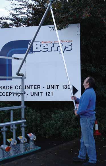
exposed to the dangers of working at height. Berry’s claim that the “Easy Riser” is an inexpensive solution to this problem and tell us that is already being retrospectively fitted to Stage 1b Vapour Recovery installations in the field.
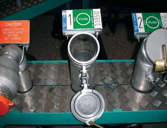
A New Cap – the solution to an old fill cap problem
Anybody who has removed a tank fill cap will be familiar with the irritating scenario of the retaining chain snapping and the cap disappearing into the manway chamber or dropping to the ground in the case of off-set filling installations. Again Berry’s have come up with a simple solution in the form of their retaining device.
T h e traditional retaining chain has been removed and replaced with a double-action bracket which simply lowers the cap and holds it in position once it has been unlocked, therefore eliminating the risk of it breaking or coming adrift. According to Berry’s their new cap is simple to retrofit and solves this long standing problem.
For more details and specification call Berry’s on 0121 558 4411 or email enquiries@dberryandco.co.uk.
By Bob Conlin, Fairbanks Environmental
Fairbanks Environmental, the Wetstock Monitoring and Management Specialists, have now extended their portfolio of compliance services to include their own DSEAR compliance service. They have developed a comprehensive survey of a site operator’s management and control of the hazardous substances which assesses a site operator’s current status of compliance with legislation, document facilities, procedures and systems of work on the forecourt.
As explained later the survey includes a risk rating process presenting the results in assessment tables. This replaces the need to also undertake an assessment in accordance with HS(G)146.
When undertaking the survey, which will take up to half a day on an average sized forecourt, Fairbanks ensures that the site operator fully understands and is involved in the process so that he/she ‘owns’the resulting assessment report and takes responsibility for the action plan remedial actions.
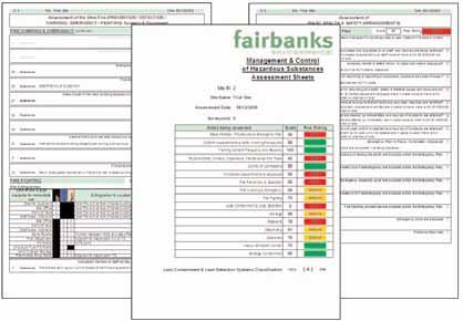
The output of the survey is a site specific Management & Control of Hazardous Substances Report which consists of :
• The risk assessment, • assessment tables, • an action plan, • a hazard classification drawing
Risk Assessment Sheets
The Assessment Sheets are divided into 16 separate areas which consist of common industry best practice control measures and key factors on the forecourt. These include; staff training, emergency plans, control of contractors, fire detection and fire fighting, safety checks and maintenance and leak containment and detection.
The assessment of each area takes the form of a series of questions which establish whether adequate control measures are in place.
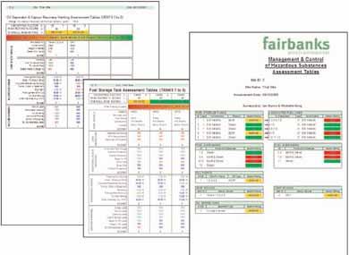
Assessment Tables
The Assessment Tables assess the risks in the areas on the forecourt where a hazardous substance will have an impact. Hazardous contents (gasoline, LPG etc) are identified and recorded and individual areas on the forecourt are classified based upon industry recognised criteria.
The concept of establishing a risk rating ‘score’as adopted in HS(G)146 is retained here which also enables group operators and major oil companies to
In order to assess the fire and explosion risks of individual key areas this section of the assessment divides them into 7 "Aspects" with each aspect being subdivided into a number of "Elements".
For example under the Aspect ‘Storage’, each tank is recorded in terms of its age, type, leak detection method, proximity to vulnerable receptors such as basements and is given its own score, rather than having a combined score for all tanks. All such data collected is stored on the Fairbanks database.
Action Plan

The Action Plan consists of a list of remedial actions, which are Fairbanks’recommendations on how to rectify any non compliances. It is intended as an aid to the site operator to prioritise and plan his actions in order to improve the Management & Control of the hazards and risks presented by Hazardous Substances on the forecourt.
The site operator is however free to decide how best to rectify such non compliances.
The Action Plan also acts as a management control document by requiring a completion date and signature by the responsible person.
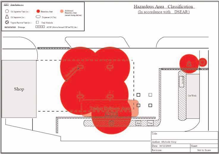
Site Drawings
DSEAR requires site operators to identify and mark all relevant Hazardous Areas. One way of doing this is to produce a site plan. Fairbanks will prepare a drawing either by surveying the site or using a current CAD layout drawing if one is available. The drawing is a view of the forecourt showing hazardous areas in relation to equipment & facilities on the forecourt. It also differentiates between the
classification of
hazardous areas present during a tanker delivery and at all other times.
Please refer any questions or enquiries to either Brian Reed, Business Development Manager or Michelle King, Audit Manager on tel: 01695 51775 or email
to
DSEAR@fairbanks.co.uk
By Dipl.-Ing. Stefan Kunter, Wolfgang Pein, Dr. rer. nat. Wolfgang Schrittenlacher
Every time you fill up your car with petrol 0.1% is lost through evaporation into the atmosphere. On its journey from the Refinery to the customers car petrol passes through three processes where petrol vapour is lost through evaporation.
Road tankers are filled at the loading gantry and then underground storage tanks are filled at the petrol station; finally the customers’vehicles are filled. In 2004 in the United Kingdom approximately 33 Million tonnes of petrol were consumed. On this basis an estimated 99,000 tonnes of petrol would have been lost assuming there were no vapour recovery systems in place. When filling road tankers and underground storage tanks at service stations, vapour recovery systems are already established in most EU countries and also in UK (Vapour recovery stages 1A& 1B). However, in the UK there is still an estimated amount of more than 33,000 tonnes of vapour emitted to atmosphere when filling vehicles. Stage II Vapour recovery is the process of collecting vapours when filling vehicles.
Hydrocarbons are amongst the gases responsible for the much spoken about greenhouse effect. Furthermore the cyclic hydrocarbons which are present in the emitted vapours are known to be carcinogenic. Clearly there are many environmental reasons to control and limit these emissions.
Vapour recovery stage I
In most European countries Stages 1A& 1B vapour recovery have already been implemented for the loading and unloading of road tankers. In addition to the fill line a vapour recovery hose also has to be connected to allow a return path for the displaced vapours. During the filling process the liquid displaces the vapour and the pressure differential acts as the driving force to expel the vapours from the road tanker and return it to storage. Vapours equivalent to approximately 35 to 40 litres of petrol are recovered when recovering vapours during the process of filling a road tanker with 35000 litres of petrol. Road tankers are predominately bottom loaded with an interlock system in place to ensure that the vapour recovery hose is correctly connected.
When unloading the road tanker at the service station a similar situation prevails, however this is slightly more complicated. The vent pipes from all petrol tanks are normally manifolded to give one vapour recovery line connected to a single elevated vent riser. Underground diesel tanks remain independent of the vapour recovery system and retain their individual vent pipes and risers. The single petrol vent riser is fitted with a pressure/vacuum valve preset to relieve at 35mb of pressure or 2mb of vacuum. When filling the underground storage tank (UST) there is a dynamic increase in pressure, however under normal circumstances this does not lead to a hydrocarbon emission. Only if there are increases in pressure above 35mb will the pressure/vent valve operate allowing an escape of vapour. (One illustration of how this situation could occur is in the event of the road tanker driver not connecting the vapour recovery line correctly).
In some instances problems have been experienced with a build up of pressure due to overfill prevention valves being incorrectly installed or not being “gas tight”. This normally manifests itself with tank fill caps flying off under pressure when being removed in order to connect the delivery hoses! In some European countries a throttle valve in the vent riser is allowed as an alternative to the pressure/vacuum valve; however this leads to higher level of hydrocarbon emission. The conditions have been studied in detail in reference /3/.
Stage II Vapour Recovery
Stage Ib Stage II
The final missing link in the vapour recovery chain in the UK is in dealing with containing the vapours displaced when refuelling vehicles at service stations – Stage II.
Stages 1b & Stage II vapour recovery at service stations are as illustrated in figure 1.
If Stage II vapour recovery is not implemented there are two potential sources of Hydrocarbon emissions to be considered. Firstly there is the emission of vapour as the vapour in the cars' tank is displaced by the incoming fuel. An additional emission at the vent riser may also be induced if Stage II Vapour Recovery is not installed; this can be as a result of a pressure drop being generated within the USTas the fuel is being delivered into the vehicle tank. This reduction in pressure can cause the ingestion of a corresponding amount of air. Because the vapour phase needs to be in equilibrium there is a tendency to maintain a concentration of hydrocarbons, this can cause a subsequent additional evaporation of hydrocarbons from the liquid to the gas phase. This in turn can lead to an eventual increase of vapour pressure in the USThence allowing an excess emission of hydrocarbons from the vent riser. This excess pressure can also lead to an increased emission of vapour when the fill line and vapour recovery line are connected for the purpose of unloading of the road tanker. The pressure increase due to evaporation in the USTis minimised when Stage II Vapour Recovery is installed because the recovered gases contain a comparable amount of hydrocarbons.
Since there are no standardised interfaces between the nozzle and the vehicle tank filler many problems were experienced with the early displacement or passive/balanced Stage II Vapour Recovery systems. This system relies on the slight overpressure within the vehicle tank to be the driving force to propel the displaced vapours back to the UST. It is however extremely difficult to maintain a gas tight connection between the nozzle and the vehicle fill point, rubber bellows were initially used for this purpose but were found to be cumbersome in operation and not very efficient. As a result of this experience the European market decided not to introduce "Balanced Systems" but favoured the development of so called "Active Vapour Recovery Systems". Active vapour recovery systems consist of a special nozzle equipped with a ring shaped suction opening, a coaxial delivery hose and a vacuum pump connecting to a vapour return pipe to the UST. Figure 2: illustrates this type of system.
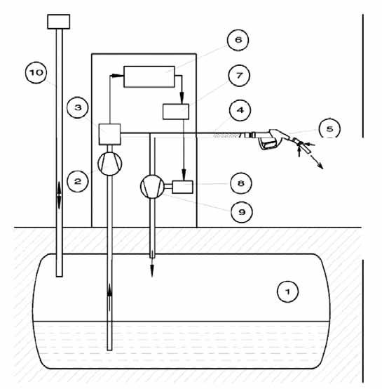
Figure 2: Active vapour recovery system
1 underground storage tank 2 fuel pump 3 fuel counter 4 double walled hose 5 nozzle 6 dispenser controller 7 operational electronic for vapour recovery system 8 motor for vacuum pup 9 vacuum pump 10 ventmast
Using an active vapour recovery system allows the displaced vapour from the vehicle tank to be recovered via the special nozzle using the suction generated by the vacuum pump. As there is no sealed connection between the nozzle and the vehicle fuel tank a certain amount of air is inevitably recovered together with the displaced hydrocarbon mixture.
Therefore the efficiency of the recovery system is clearly less than 100 % but 85% efficiency should be easily achievable. To achieve this level of efficiency it is necessary to gear the vapour recovery rate to the speed of the fuel delivery. Currently there are two widely used solutions to this problem, the first system employs a constant speed vacuum pump and the vapour flow is controlled by an electromagnetic valve. The second system uses a speed controlled servo motor as shown in figure 2.1
In a normal refuelling operation the fuel counter (3) sends a signal to the dispenser controller (6) according to the fuel flow. This signal is used to calculate the total fuel dispensed and the dispenser controller sends a message to the point of sale (POS) recording the transaction. The fuel flow signal pulses are "mirrored" by the dispenser controller and are provided at a separate port for the electronic operation (7) of the vapour recovery system. Due to Weights and Measures regulations a decoupling is necessary to exclude a retroaction. The electronics control the number of revolutions of the vacuum pump (or controls the electromagnetic valve) in order to equalize fuel flow and gas flow within the tolerance limits of 95 % to 105 %.
1 There are also other types of vapour recovery systems, such as liquid driven vacuum pumps and systems with a proportioning valve in the nozzle controlled by the liquid flow. These systems are not widespread in use and are not discussed further.
Since the control characteristic is nonlinear an adjustment and calibration of the system is necessary. This is generally achieved by carrying out a so called "dry calibration"2. The setup is shown in figure 3.
2 in Switzerland a wet calibration system is used
Vapor Recovery Monitoring Dispenser electronic, can be used in all dispensers

Figure 3: Dispenser with vapour recovery system
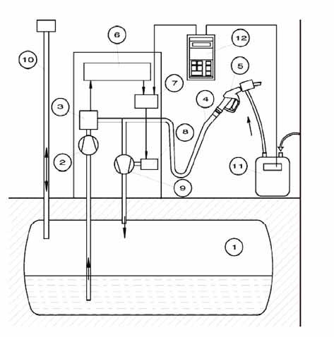
1 underground storage tank 2 fuel pump 3 fuel counter 4 double walled hose 5 nozzle 6 dispenser controller 7 operational electronic for vapour recovery system 8 motor for vacuum pup 9 vacuum pump 10 vent mast 11 gas meter 12 hand terminal and external gas meter for dry calibration

The system has to be connected as shown in figure 3. The hand terminal (12) sends a signal to the operational electronics (7) of the vapour recovery system simulating fuel flow (typically 40 l/min). The operational electronics generates a signal for the valve position or for the speed of pump according to the preset value. The actual gas flow is measured by the gas meter (11) which is also connected to the hand terminal. This process is carried out for the whole range of operational fuel delivery speeds. The controller in the hand terminal calculates the corrected values and these are transferred to the operational electronics of the vapour recovery system where they are stored in non volatile memory.
Following the simulation of a fuel flow of 40 l/min a gas flow of 40 l/min (+/5%) should be indicated on the display of the hand held terminal if the so called k-factor (as explained below) is preset to 1.00. Once this calibration and test procedure has been carried out the system should be ready for operation assuming that the installation has been correctly carried out.
One complicated issue is the volume transport efficiency of the vapour recovery system which is dependent on the concentration of hydrocarbons in the vapours. The effect is generally more significant in valve systems and depends also on the construction of the vapour pump. There are systems available which are virtually independent of the hydrocarbon concentration and others which can accommodate a dependence of up to 15 %. This effect is taken into account by the so called “k-factor”. If there is no hydrocarbon concentration dependence the k-factor equals 1,00 and if the effect is 15 % the k-factor equals 1,15. The k-factor must be determined in type test procedures described in publications 4, 5, 6, detailed at the end of this article. The k-factor represents the decrease in volume transport efficiency determined at about 20 °C. Because the hydrocarbon concentration is temperature dependent so is the decrease of the volume transport efficiency. This temperature effect is ignored and so a slight deviation can be expected. At lower temperatures the vapour recovery rate is somewhat higher and at raised temperatures it is lower.
This error was generally accepted during the introduction of Stage II Vapour Recovery systems for the purpose of simplification. Stage II Vapour Recovery Systems have now been implemented in several European countries. The status of the implementation is given in the following table together with an estimate for the monitoring devices:
Country
Germany Switzerland Sweden Netherlands Austria Italy Luxembourg Denmark France UK Portugal Spain Czech Republic Belgium Finland Hungary Norway No. Service Stations
15722 3559 4046 3600 2878 23400 240 2308 15500 11435 2500 8522 1965 4177 1892 1630 1995 VR% *
100 100 90 90 95 100 100 78 >95 <50 0 <5 90 1 6 80 2 Start of Installation
1 Jan 1993 1 Feb 1992 1 Jan 1992 1 July 1996 1 Jan 1993 1 May 1996 1 Jan 1992 1 April 1995 April 2001>3000m3
1 Jan 2002
1996 Installation Completed
1 Jan 1998 1 Jan 1995 1 Jan 1995 1 July 1999 1 Jan 1998 1 July 2000 1 Jan 1996 1 Jan 2000 Oct 2002 Performance Monitoring % **
29 8 <0,5 0 0 0 0 0 0
0 0 0 0 0 0 0 Monitoring Installation Completion
12-2007 12-2009
* figures 1 january 2003 by DGMK ** estimated for October 2005 From the 17 countries listed 11 are equipped with Stage II Vapour Recovery ,it is anticipated that most European countries will follow this trend to reduce the VOC emissions.
Vapor Recovery Monitoring Display, optional display for the POS/BOS area to get status information from the Vapor recovery system
Under normal working conditions it became apparent that vapour recovery systems could become faulty without the knowledge of the service station manager. Independent studies carried out by various organisations identified that between 30% and 40 % of the operational systems were not working correctly. For this reason several countries adopted a policy of the mandatory monitoring of vapour recovery systems to ensure compliance with the required performance standards. To date this is required in Germany, Switzerland and California. Since the introduction of monitoring devices in Germany, tests have shown that the general performance or vapour recovery systems has improved drastically.
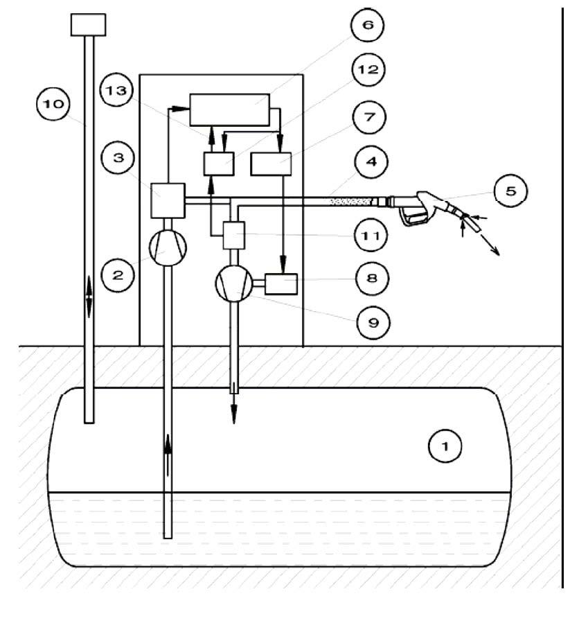
The structure of the vapour recovery system with a monitoring device is shown in figure 4.
The monitoring device consists of a gas flow sensor (11) situated in the vapour recovery line. An electronic evaluation unit (12) is also connected in order to determine the gas flow during refuelling operations. This electronic evaluation device has an impulse interface connected to the same output as the operational electronics of the vapour recovery system. In the evaluation electronics the recovery rate is calculated and compared with the allowable limits. If the recovery rate is out of tolerance an alarm signal is generated which alerts the service station manager that there is a problem. The alarm criteria adopted in Germany and Switzerland is that if the average vapour recovery rate calculated over 10 consecutive refuelling operations is out of a tolerance range of ± 15 % an alarm signal is generated. This also triggers the start of a timed period during which a repair should be affected, failure to repair the system within this time period (typically 7 days) will cause the monitoring device to turn off the defective fuelling position until such time as repairs are carried out. The time period of 7 days was adopted in order to allow an adequate time for the
Figure 4: Vapour recovery system with monitoring device
1 underground storage tank 2 fuel pump 3 fuel counter 4 double walled hose 5 nozzle 6 dispenser controller 7 operational electronic for vapour recovery system 8 motor for vacuum pup 9 vacuum pump 10 vent mast 11 flow sensor of monitoring device 12 evaluation electronic of monitoring device 13 switch off signal output
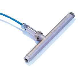
Vapor Recovery Monitoring Gas flow meter, will be connected to the electronic appropriate checks and repair of the system to be carried out. Assuming the repair was successful the alarm can be reset and the fuelling point returned to operational status. As the monitoring device described operates entirely independently of the vapour recovery system there is a high level of confidence, that faults will be readily detected.
Another system is available using the gas flow data to correct the gas flow generated by the vapour recovery system. This has the advantage that variations in the vapour recovery rate due to temperature changes will not lead to an alarm. Furthermore moderate degradations of the vapour recovery system can be compensated. On the other hand, since such systems are not independent of the vapour recovery system any error in the flow sensor of the monitoring device may not be detected and under these circumstances a fault condition may not reported even though the system is not working properly!
Type tests of vapour recovery systems and monitoring devices and tests on the station
To ensure the fulfilment of the regulations the equipment has to be type tested by an independent authority Aproposal for a harmonized type test for Europe is given in the C.E.C.O.D documentation. This proposal takes into account the experience gained so far.
To ensure that the systems function correctly following installation and commissioning test procedures should be carried `out in accordance C.E.C.O.D paper (4). There is also a necessity for periodic tests to be carried out to ensure continued operation
The experience in retrofitting monitoring systems in Germany has shown (after 15000 installations) that it is necessary for field engineers involved in the installation process to undergo specific training to ensure successful implementation of vapour recovery and their associated monitoring systems.
Upshot for the UK
The environmental implications for the UK have been the subject of ongoing discussion for a considerable time.
Finally it looks as if Stage II Vapour Recovery and associated monitoring devices will become a standard requirement on UK sites in the foreseeable future. Experience gained in other European countries shows that it is certainly more cost effective to install/retrofit both systems simultaneously.
With Stage II Vapour Recovery systems in place an overall positive effect on the air quality can be expected with the inhalation of carcinogenic substances by the customer at the petrol pump greatly reduced /13/.
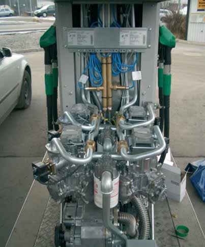
Field installation of an Vapor Recovery Monitoring system
Bibliography
/1/ DGMK Forschungsbericht 4590; Messung und Ermittlung von KohlenwasserstoffEmissionen bei Lagerung, Umschlag und Transport von Ottokraftststoffen und Prüfen von Verfahren zur Beherrschung dieser Emissionen (1976); DGMK Research Report 4590; measurement and determination of hydrocarbon emission in storage, loading and transport of motor gasoline and test of procedures to control this emissions (1976): In this report a value 0,94 g/l was determined on the average ranging from 0,7 g/l to 1,4 g/l depending on situation and on temperature. see also: Scott Research Laboratories Inc; Scott project number 2874; Investigation of passenger car refuelling losses; final report (sept. 1972)
see also: DGMK Forschungsbericht 246; Verminderung von Emissionen beim Betanken von Kraftfahrzeugen mit Ottomotoren (1980) DGMK Research report 246; Reduction of gasoline car refuelling emissions (1980) /2/ BPstatistical review of world energy (june 2005) states an oil consumption of 80.8 Mio metric tons in the UK for the year 2004; The International Energy Agency (IEA) states a demand of gasoline fuel for the UK of 0,45 Million barrels per day in 2004; this can be recalculated to 26,7 Million liters/a or with the density of about 0,8 kg/l to 33 Mio tons per year. /3/ DGMK Forschungsbericht 504; Drücke und Volumenströme im System Tankwagen/Tankstelle bei der Anlieferung von Ottokraftstoffen (1996); DGMK research report 504; Pressures and flowrates in the system tank truck/petrol station during delivery of gasoline (1996). /4/ C.E.C.O.D. Committee of European Manufacturers of Petroleum Measuring and Distribution Equipment: Proposal for test procedures for vapour recovery systems and vapour recovery monitoring devices in metering petrol pumps/dispensers and dispersed unit delivery systems on filling stations; Issue 10; January 2005. /5/ Systemprüfung für aktive Gasrückführungssysteme und deren Überwachungssysteme in Deutschland ; Merkblatt 1. (Type test of active vapour recovery systems and their automatic monitoring systems in Germany; reference sheet 1) /6/ Buwal Handbuch für die Kontrolle von Tankstellen mit Gasrückführung (Switzerland) /7/ Overview as prepared by the CECOD committee Subgroup 7 (October 2003) /8/ TÜV Rheinland Sicherheit und Umweltschutz GmbH; Ermittlung der Volumenrate und des Rückführungsgrades von Gasrückführungssystemen an Tankstellen in Nordrhein-Westfalen (February 1998) Or DGMK Forschungsbericht 550-01/1 Messaktion zur Überprüfung von Gasrückführungssystemen an öffentlichen Tankstellen in der Freien und Hansestadt Hamburg (5/2001); DGMK research report 550-01/1 Measurements to check vapour recovery systems of public retail stations in Hamburg (5/2001) -9/9/ See DGMK research report (4/2003) under http://www.dgmk.de/downstream/report_550-05_%20englisch.pdf /10/ 21. BImSchV Verordnung zur Änderung der Immissionsrechtlichen Vorschriften vom 6. Mai 2002 ( this regulation contains the changes given for the vapour recovery system and the basics for the implementation of the automatic monitoring device) /11/ Prüfung von Gasrückführungssystemen; Merkblatt 908 Teil 1; VDTÜV 8/2005 (Test of vapour recovery systems; reference sheet 908 part 1; VDTÜV 8/2005; this reference sheet contain also the procedure on how to test the monitoring system on the site) /12/ Process Guidance Note 1/14 (XX); November 2005; see www.defra.gov.uk /13/ Final Regulatory Impact Assessment on Petrol Vapour Recovery stage II controls (PVR II); November 2005; see www.defra.gov.uk
/6/ Buwal Handbuch für die Kontrolle von Tankstellen mit Gasrückführung (Switzerland) /7/ Overview as prepared by the CECOD committee Subgroup 7 (October 2003) /8/ TÜV Rheinland Sicherheit und Umweltschutz GmbH; Ermittlung der Volumenrate und des Rückführungsgrades von Gasrückführungssystemen an Tankstellen in Nordrhein-Westfalen (February 1998) Or DGMK Forschungsbericht 550-01/1 Messaktion zur Überprüfung von Gasrückführungssystemen an öffentlichen Tankstellen in der Freien und Hansestadt Hamburg (5/2001); DGMK research report 550-01/1 Measurements to check vapour recovery systems of public retail stations in Hamburg (5/2001) -9/9/ See DGMK research report (4/2003) under http://www.dgmk.de/downstream/report_550-05_%20englisch.pdf /10/ 21. BImSchV Verordnung zur Änderung der Immissionsrechtlichen Vorschriften vom 6. Mai 2002 ( this regulation contains the changes given for the vapour recovery system and the basics for the implementation of the automatic monitoring device) /11/ Prüfung von Gasrückführungssystemen; Merkblatt 908 Teil 1; VDTÜV 8/2005 (Test of vapour recovery systems; reference sheet 908 part 1; VDTÜV 8/2005; this reference sheet contain also the procedure on how to test the monitoring system on the site) /12/ Process Guidance Note 1/14 (XX); November 2005; see www.defra.gov.uk /13/ Final Regulatory Impact Assessment on Petrol Vapour Recovery stage II controls (PVR II); November 2005; see www.defra.gov.uk
By Brian Baker, APEAChairman
The APEAis the subject of constant change. As conditions change within our industry many people retire or move on to serve elsewhere, others join us from outside of the industry.
Your council is continually looking for new blood! Some council members have served for many years and are conscious that a fresh look at things may offer enormous benefit to the association as a whole.
If you have the drive, ambition (and most importantly the time available) to increase your involvement in the APEA your input would be most welcome. By involving yourself in the activities of your local branch you will be making a great contribution to the association, and if you feel you have something to offer at council level - don’t be shy – put yourself forward!
Working with a respected organisation such as the APEAis not only a rewarding experience but also provides a great networking opportunity. By serving on council you will be at the forefront of our industry and in a position to help mould its future.
If you are interested, please let us know. For an informal chat, please contact Paul Craven on 07702 447959 or e-mail on paul_craven@uko2.co.uk
Go on you know you would like to.
APEACouncil
Branches
Eastern
The APEAEastern Branch met at the Limes Hotel Needham Market on December 13th for its December meeting and Christmas lunch.
The meeting was well attended with excellent presentations given by Chris Cooper and Lee Markham of UPPwho talked about UPP’s new products and vacuum test of chambers, manholes and secondary containments. Brian Baker, Milton Keynes County Council, gave an Industry update on current issues and that an APEAbook is being prepared.
Brian asked for individuals or companies to provide information of interest, story’s, history etc. If you have anything please forward it via the association web site.
Jamie Thompson gave a briefing on APEAactivity in Denmark.
Anton Martiniussen of the Forecourt Equipment Federation gave an update on Stage II vapour recovery. The day was concluded by an excellent Christmas Lunch for the members. Anton Matiniussen Branch Secretary
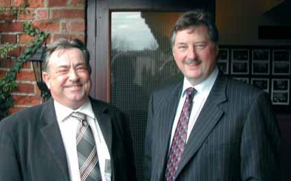
Brian Baker (APEAChairman) and Anton Martiniussen (Branch Secretary)

APEANW Branch Technical Meeting 22nd November 2005
Mr Steve Jones, Treasurer of the APEANorth West Branch opened our second and final meeting of 2005 and extended a warm welcome to the gathering of 35 members and their guests.
Yet again the level of discussion at the pre meeting registration and over lunch reminded our branch secretary, Bob Conlin, what a valuable opportunity our branch meetings present for our members to meet and discuss topical issues and network in such a relaxed and friendly forum.
The meeting was then treated to four excellent technical presentations on vapour recovery, prefabricated forecourt installations and oil separators.
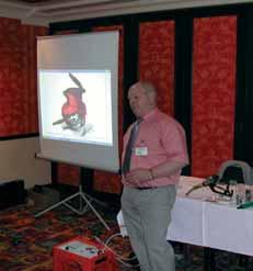
Mr Paul Reyner from OPW gave a presentation on the OPW Vapour Recovery System.
Mr Reyner started his presentation with a potted history of his company from formation in 1892 through to the present day. He discussed the advantages of the “Vapour Saving System” for both Stage One and Stage Two vapour recovery installations. He then discussed the other OPW products including overfill valves and nozzles which recently achieved approval and are made in China.
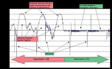
He went on to explain in detail the advantages of the Vapour Saving System, providing evidence that the system could achieve good savings particularly when used on Stage One systems where the tanks release vapour during the night time or at times when the tanks are at rest. He also pointed out that the Vapour Saving System, using membrane technology, was designed to keep tanks at negative pressure thereby saving harmful emissions and losses. He explained in more detail how the membrane worked and advised that the membrane had a 12,000 hour life cycle. The system was ATEX certified, ULapproved, TUV approved and CARB approved. He advised the meeting that ongoing development of the product was taking place and that there was a Stage Two Vapour Saving System trial site.
Tom Hocking and Jacque Williams of D. Berry & Co gave a presentation on Prefabricated Installation Products.
They started their presentation with a potted history of D. Berry & Co which was created in 1966 as a general pipe supply company and has evolved into a specialist supplier for the industry. They presented the up to date range of Prefabricated Installation Products namely “Atlas”, which is a sealed chamber which directly connects to the manhole lid, containing all of the tank
connection points. They pointed out that the modular construction not only modernised and kept the tank water tight but also lent itself to ease of installation and ongoing maintenance.
They then presented the Vent Master, which is a modular fill point and vent arrangement. They pointed out the versatility of the product, allowing a multiple grade fill point and multiple variations to the vent risers.
Finally they described their innovative adjustable vent riser which gave access to the p&v valve at ground level.
Joanne Bradley of the Environment Agency and committee member of the North West Branch of the APEA gave a preview of the new PPG3 (Pollution Prevention Guidance) Regulations.
She pointed out that the guidance was in respect to Oil Separators mainly on retail petrol filling stations but also an overview to other applications. She pointed out that by selecting the correct Oil Separator contamination of oil to surface water and foul drainage could be averted. She advised that the design of the surface area drainage system and associated Oil Separator was of paramount importance but that an interceptor of less than 7,600 litres capacity on a petrol forecourt was likely to be inadequate. At no time must vehicles washings be allowed through the Oil Separator. If an Oil Separator of less than 7,600 litres capacity were envisaged it would only be permissible following consent of written Risk Assessment. She advised that automatic closure devices and alarms should be fitted.
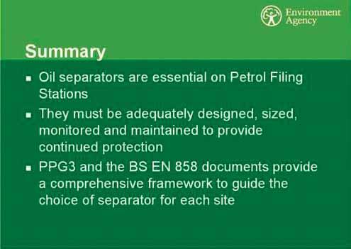
She believed that strict attention needs to be given to Oil Separator Management Systems and in every case forecourt Oil Separators must be inspected at least annually. She advised the meeting that the new guidance would be available on and after 16th January 2006 which would include an online list of approved Oil Separators.
Barry Young from Conder Products Ltd gave a presentation on the operation and maintenance of Forecourt Petrol Interceptors.
Barry commenced his presentation with a history of Conder Products Ltd which commenced manufacturing in Winchester in 1947. He explained various products which the company created between 1947 and 1972 when Conder Products made the first plastic Oil Separator.
He went on to explain and describe the uses and merits of selecting Class 1 or Class 2 Separators. He explained the need for closure devices and alarms and how they operated and went on to point out that interceptors ideally should be maintained on a six monthly basis with appropriate checks and tests on closure devices and alarms.
The meeting was then closed and everyone retired to the Buffet Lunch and informal session.
Branch Chairman Mr Steve Devine
Branch Representative Contact Details
Ian Taylor - Eastern
Hytek (GB) Ltd, Delta House, Green Street, Elsenham, Bishops Stortford, Herts CM22 6DS Tel: 01279 815600 Fax: 01279 812978 iantaylor@hytekgb.com
Tom Hocking - Midlands
D Berry & Co (PFS) Ltd Unit 130 Middlemore Ind Estate Kentish Road Birmingham B21 0AY Tel: 0121 558 4411 Fax: 0121 555 5546 enquiries@dberryandco.co.uk
Mike Silmon - North East
W O Silmon Ltd Industry Road, Heaton, Newcastle upon Tyne, Tyne & Wear. NE6 5XB. Tel: 0191 224 0777 Fax: 0191 224 0707 associationtreasurer@apea.org.uk
Geoff Oldham - North West
Suresite Ltd 3 Eastway Business Village Olivers Place, Fulwood Preston Lancashire PR2 9WT Tel: 01772 790901 Fax: 01772 790902 geoff.oldham@suresite.co.uk
Ian Hillier - Scottish
Inverclyde Council Municipal Buildings, Clyde Square, Greenock PA15 1LY Tel: 01475 717171 Fax: 01475 712747 ian.hiller@inverclyde.gov.uk
Philip Monger - Southern
Petrol Retailers Association Meadowside, West End, Sherbourne St John, Basingstoke, Hants. RG24 9LE.
Tel: 01256 850164 Fax: 01256 851273 philmongerpra@ukonline.co.uk


