44 minute read
News


India: Shell petrol pumps back after 3 decades
The government has decided to allow Shell India Private Limited (SIPL), a subsidiary of the Shell group of companies, to market transportation fuel in India. Shell will now be able to set up its petrol pumps all over India after three decades.
Advertisement
Shell was nationalised in 1972 and became Bharat Petroleum Corporation Limited. The authorisation is, however, subject to the company furnishing a Rs 500 crore bank guarantee to the government. This will go towards fulfilling its commitment of investing Rs 2,000 crore in building infrastructure in the hydrocarbon sector. SIPL will also have to stick to the yearly investment target set by the government. The company will also be required to set up 11 per cent of its retail outlets in farflung areas, according to an official press release issued here today.
SIPL plans to set up around 2,000 retail outlets across the country. The company informed the government that it would prefer to source its supplies from domestic refineries. It also plans to make use the installations and depots of public sector oil companies in the country. "This decision goes a long way towards fulfilling the government's goal of bringing in more players in the marketing of transportation fuel so that consumers have a wider choice of quality products and services. At the same time, the new entrant in the lucrative marketing segment of the Indian petroleum sector has to commit investment for creating more infrastructure in the country," the press release said.
In addition to the 20,000 retail outlets run by the public sector, the government has granted marketing rights to the Reliance group (5,849 outlets), Essar Oil (1,700) ONGC (600) and Numaligarh Refinery (510). These entities would also have to fulfill the government's condition of investing in infrastructure in the hydrocarbon sector.
Iraq: 7 Dead in petrol station blast
At least seven people have been burned to death at a petrol station in an impoverished Baghdad neighbourhood after a spark turned the site into a raging inferno. Another 20 were badly hurt, and rescue workers and US soldiers said more bodies remained trapped inside.
The station was still burning hours after it was set alight, trapping helpless people who had been queuing to buy petrol. The fire did not appear to be a criminal or terrorist act, but the cause was not immediately clear today.
Local firemen were overwhelmed by the size of the blaze and residents risked their lives to try to rescue those inside, drenching themselves in water before racing into the roaring flames. "There are still charred bodies littering the ground, but we can't get to them," said Hassan al-Awani, 18, one of the civilian volunteers. "They are scattered all over in tiny pieces so there's no way to tell how many more there are." Iyad Hashem, an official at Karameh hospital, said that at least seven people had been killed and 20 others badly burned, most of them in critical condition. "There may be more wounded because some were taken to other hospitals. Eighteen people are in critical condition, burned over 70 to 90 per cent of their bodies."
He pointed to the hospital's list of dead, which was blank. "I can't give you any names. They have been burnt beyond all recognition." The stench of burned flesh was thick in the air around the site, in the city's poor Alawi quarter.
Firefighters gave up hope of putting out the blaze and asked US troops to bring a bulldozer to dig up earth to cover the station. Witnesses said dozens of people were waiting to buy petrol, one of the most coveted commodities in post-war Baghdad, where many are still without electricity and running water. The streets of the city are lined with men and children selling petrol out of makeshift containers, and some witnesses said they thought a spark from someone dragging his purchase along the ground had set off the blaze. Gunfire was also heard in the area just before the fire erupted. Most residents said this was in celebration of electricity briefly returning to the neighbourhood, but it was unclear if shots hit the station.
Baghdad residents have taken to firing in the air any time electricity is turned back. Witness Ishab Fajr, 19, said: "The fire spread so fast that people's shirts caught fire as they were running away." US troops quickly arrived on the scene after noticing the tower of smoke in the sky. "There was very little we could do," said one of the soldiers, who asked that his name not be used.
After US troops cordonned off the area, relatives and neighbours became angry that they could not get into the site to continue the search for remains. "Why won't you let us through?" one woman shouted as US soldiers kept back the crowd. "We want to get at our loved ones." One American soldier embraced a young boy who was weeping on the pavement. The child said his father was missing.
South Africa: warning - your cell phone could cause fire
Answering a cell phone while filling up at a petrol station might prove disastrous. This warning, issued by the South African Retail Motor Industry (RMI), follows reports of ringing cell phones causing fires at fuel stations overseas. It is believed that sparks from the phones ignited petrol fumes.
According to the RMI, using a cell phone while filling up is not a high-risk activity. South African Bureau of Standards managing director of test laboratories Thembani Bukula said it was highly unlikely that a ringing cell phone could cause either enough heat or electromagnetic energy to ignite petrol fumes. "Tests at our laboratories have indicated that cell phones tend to heat up after conversations longer than 10 minutes, causing discomfort to users, but certainly not generating enough heat to set off a fire," he said.
Cobus Roux, an engineer at the Council for Scientific and Industrial Research, said that in extreme circumstances a loose battery in a cell phone might cause a spark.
Mobile Phones Again!
Reports have resurfaced on the Internet rumor that cell phones could cause a fire if they ring while you are refueling your vehicle at the gas station.
This rumor is making the e-mail rounds again in the guise of a warning that could save your life. This rumor has been proclaimed an urban legend by the Web site, Urbanlegends.about.com. Likewise by snopes.com, another Web site that specializes in myth busting.
But, perhaps the most authentic information about cell phones at gas stations comes from the Petroleum Institute of America (PEI). According to PEI, although there has been a documented increase in automotive refueling fires, there is no evidence that any of them were caused by a cell phone.
PEI brought Motorola, a leading cell phone manufacturer, into the picture. Motorola agreed with PEI that there is no evidence to suggest that cell phones pose any hazard at gas stations. (It's
the cell phone users that create the hazards. One could walk out in front of you on his way to pay for his gas and if you're busily talking on your cell phone, you could run over him.)
Because of the increase in refueling fires, PEI began to document the incidents that could not be attributed to a running engine or cigarette smoking, both known to be causes of fires at the gas pump. In its investigation, it found fewer than 150 fires that appeared to be caused by static electricity discharges.
But, don't start carrying a portable fire extinguisher with you when you pump your gasoline. PEI notes that Americans pump gas into their vehicles between 11 billion and 12 billion times a year without incident. So, you have a better chance of winning the lottery than of catching on fire at the gas station from static electricity. In its research,
PEI did uncover some interesting information about static fires. Since May of 2000, it received 146 reports of fires from 39 states and Washington, D.C. (It should be noted that some states such as New Jersey require the gas station attendants to pump gas for their customers.) Static-sparked fires occurred with both conventional gas nozzles and vapor recovery nozzles.
None occurred with balance system nozzles. PEI found that the static fires occurred on all types of gas station lot surfaces: concrete, asphalt, stone, crushed rock and dirt. Most of the victims of these fires were women and at least 70 of the fires occurred when the refueler had reentered her vehicle during the refueling process. There were five such fires recorded in Illinois and eight in Missouri. The victims in the fires sustained varying degrees of injuries, ranging from singed hair to third-degree burns and one death was recorded due to a gas pump fire caused by static electricity. Some vehicles were destroyed by the fires and others were damaged minimally to extensively.
PEI and the American Petroleum Institute both assure that static electricity caused fires are extremely rare, but nevertheless offer words of advice to prevent such an occurrence.
First and foremost, is to remain outside the vehicle during the entire refueling process. If you must re-enter your vehicle for some unavoidable reason, be sure to discharge any static electricity by touching the metal on your car door before you go to the gas tank and touch the gas nozzle. If all else fails and a flash fire should occur, PEI advises that you leave the nozzle in the fill pipe of your vehicle and back away from the vehicle as quickly as you can. Notify the gas station attendants
Press Releases
Texaco, Ireland further cement their relationship with Fairbanks Environmental
Fairbanks Environmental who already monitor a number of Texaco sites in Ireland are delighted to announce that Texaco have now awarded them a contract to provide wetstock management services to its company owned dealer operated network.
John Prendeville, Texaco's Retail Engineer said, "Following implementation the Fairbanks wetstock monitoring should lead to improved operational performance."
No site will need to update or purchase any equipment as Fairbanks will use different methods to retrieve all the reconciliation data required for their Statistical Trend Analysis.
All parts of the sites petroleum system are monitored, including tanks, lines and offset fills and all unacceptable wetstock variances are investigated by the Fairbanks team of analysts.
Over a period of four weeks comprehensive site inspections have been carried out by Fairbanks' senior auditor and they have employed Texaco's Pump Maintenance contractor, Forecourt Systems to carry out pump meter audits on all the sites.
Fairbanks has been monitoring Chevron/Texaco's UK network for a number of years and their Director, Bob Conlin commented, "We are very pleased to further extend our service to Texaco's sites in Southern Ireland and we are confident of not only providing a first class risk management service but also facilitating major cost savings."
For more information please contact:
Brian Reed
Sales & Marketing Co-ordinator
Fairbanks Environmental
Tel: 01695 - 51775 brianreed@fairbanks.co
Fairbanks Environmental Ltd the Wetstock Monitoring & Management Specialists (based in Skelmersdale, Lancashire) have been awarded the highest honour that can be bestowed on a UK business, The Queens Award for Enterprise.
Winners are selected under strict judging procedures with Fairbanks winning through against significant competition. Fairbanks, only one of fifty winners in the Innovation category, gained the Award for the development of their IT based systems for the early detection of leaks at petrol filling stations which in turn reduces the risk of pollution and protects the environment. The judging criteria included continuous development, resulting in substantial improvement in business performance and commercial success sustained over a period of not less than five years.
Steve Jones, co founder and Director of the company commented “We are absolutely delighted to have been judged to be among the best of UK companies and to receive such an endorsement of the company’s achievements. What is really pleasing is that the award is given to the company as a whole and therefore recognises the contribution made by our employees. We are confident Fairbanks will continue to grow and we are looking forward to expanding our service to new customers and industries throughout the UK and Europe.”
Fairbanks awarded Britain’s most coveted
New Publications
Petroleum Road Tanker Design and Construction
June 2003 PUBLISHED BY THE INSTITUTE OF PETROLEUM, UK
This publication has been produced by the Road Tanker Panel of the Institute of Petroleum, with the assistance of a number of vehicle, tank and service equipment manufacturers. It is intended to provide comprehensive recommendations for the design and construction of complete road tankers for the conveyance of petrol, kerosine, diesel and gas oil. In particular it provides recommendations for design and construction to facilitate the safe loading of petroleum products in distribution terminals.
The publication provides a common standard for design, construction and operation, and raises awareness of design factors that may affect safe operation, compatibility with loading gantries and product quality.
This new publication replaces IP Petroleum Road Tanker Design and Construction 1999 and IP Bottom loading, vapour collection and overfill prevention 1995, and takes into account the requirements of ADR 2003.
Essential reading for manufacturers of vehicles, tank shells and service equipment, distribution contractors and oil companies. ISBN 085293 387 8 Full Price £90.00 IP Members Price £67.50 APEAmembers receive a 15% discount on the full price cost
Inland Waters Oil Spill Response: a guidance document incorporating the strategies and techniques for responding to inland surface water oil spills in the UK
August 2003 PUBLISHED BY THE INSTITUTE OF PETROLEUM, UK
These new Guidelines were developed jointly by the Institute of Petroleum and the Environment Agency for England and Wales.
Oil spills on surface water can originate from a variety of sources, including industrial and domestic installations, pipelines, road tankers, storage tanks and shipping incidents. These new Guidelines summarise some of the strategies open to a response team under a range of different circumstances. Priorities are assigned to the various necessary actions, taking into account the Health and Safety aspects of the response. Consideration is also given to the threats to natural, industrial and amenity resources.
The methods available for the containment and recovery of oil are summarised, and their strengths and weaknesses listed. Emphasis is given to the need for good co-operation with Local and National resource groups, in order that an integrated clean-up system is implemented, and the most effective use of equipment and manpower is made. The Guidelines also include sections covering the temporary storage of recovered oil and oily debris, as well as briefly describing its disposal and the eventual restoration of the spill site.
The Guidelines take account of current United Kingdom, European and US technology, and make essential reading for anyone involved in the practical aspects of the clean-up of inland oil spills on surface waters.
ISBN 085293 385 1 Full Price £90.00 IP Members Price £67.50 APEAmembers receive a 15% discount on the full price cost
These publications can be ordered from:
Portland Customer Services Commerce Way Whitehall Industrial Estate Colchester CO2 8HP, UK Tel: +44 (0)1206 796 351 Fax: +44 (0)1206 799 331 Email: sales@portland-services.com Web: www.portland-services.com
Obituary: Bob Holdaway
By Jamie Thompson
Bob Holdaway died on 10 June 2003 aged 88.
It is with regret that we announce Bob's death, and below a close colleague and retired member of the APEA John Corfield provides a personal tribute to Bob and his work in both Petroleum and Trading Standards.
To the APEA he will always be remembered as one of a small group of founders who in 1958 decided to create this association and for many years served on the Council. He was chairman in 1973 and prior to that held the post of Editor.
He started training sessions for petroleum inspectors and in 1966 as a young inspector I remember attended one he had arranged in Shrewsbury at Attingham Park. He managed to get many people from all walks of industry to give their time to impart knowledge to those eager 50 participants, in such wonderful surroundings. He often spoke of the early visits the Association made to Germany in the 1960's when deciding upon the merits of permitting self-service at petrol stations and the fun they had when the work was done. When Bob retired he was made an Honorary Life Member of the APEA. He then became a professional critic and supporter of the APEA, attending many of our conferences and exhibitions and whenever I spoke to him wanted to know what was going on. In my time as editor he often phoned me with words of encouragement, criticism and suggestion and I will miss those phone calls.
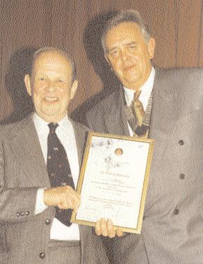
Bob was presented with a Special Achievement award for a lifetime of work for the APEA at the annual dinner marking the 40th anniversary of the Association.
Jamie Thompson
A Personal View of Robert Primmer Holdaway 1915 - 2003 by John Corfield
Bob was Chief Inspector of Weights and Measures in Shrewsbury and recruited this naive country lad to be his junior assistant in 1951. This was the start of my professional career and I have always been grateful for the start he gave me over half a century ago. Over the years Bob always treated me like a son, and sometimes still his junior assistant!
Bob was always full of life and up to only a few weeks before his death, had strong interests and opinions about many aspects of life. He was always keen to chat on any subject you care to mention from antique scales, social issues, and politics to sport, cricket and soccer being his particular favourites. He enjoyed life to the full, meeting people, history, working in his garden maturing gladioli to perfection, browsing antique shops and centres for that bargain to join his wonderful collection of antique scales.
A unique collection that was started by Bob's grandfather over 110 years ago in Winchester, no surprise to learn that Bob was a member of the International Society of Antique Collectors attending conferences in this country and the USA. He was a member of the Shropshire Antique Collectors a past member of the Shropshire Antique Society and a member of the National Trust doing stints every season at Attingham Hall.
He never seemed to be idle and up to three months ago took two to three mile walks around the fields and streets of Bayston Hill every day no matter what the weather.
Bob was immensely proud of his family professional tradition his father uncle and grandfather all served as chiefs of weights and measures inspectors in Stoke Crewe, Winchester, Southampton and Devon. Bob was born on 19 January 1915 later attending Crewe Technical College where he obtained a national certificate in Engineering. He joined the weights and measures department in Crewe as a junior assistant in 1933 and six years later was appointed chief inspector of weights, measures and petroleum in the town of Berwick upon Tweed.
From 1941 to 1946 Bob served in the RAF working on camouflage and decoy sites. He then served as an inspector for Kent and Shropshire in the immediate years after the war. For the next 25 years he served as Chief Inspector for Weights and Measures, Petroleum and Explosives for Shrewsbury Borough Council.
Bob was a life member of the Trading Standards Institute.
In 1958 Bob was one of the founders of the Association for Petroleum Acts Administration and held the post of Editor for some years. He was an Honorary Life Member of the Association.
Bob a family man married the late Vera in Crewe in 1940. Condolences go to his sons, Richard and Alex, grandchildren Scott and Heidi and four great grandchildren. Hadleigh, Emily, Sophie and Alice in their loss.
They lost a lovely father and grandfather, I and many others lost a good friend and an encyclopaedia on weights and measures history.
Bob Holdaway receiving a special award from Chairman John Boudry at our 40th anniversary dinner in Telford.
Petrol Pumping Systems - The Drive for Change Examining the trend towards installing pressure systems in Europe
By Jamie Thompson
Development of the Service Station in Europe
Historically the first distribution of petrol in the early 1900's was by the 2-gallon can, which was poured into the vehicle via a funnel; there were not enough vehicles on the road to warrant the installation of any thing larger. As the motorcar sales grew the need for an improved distribution system brought about the first underground tanks and pumps. These tanks were quite small with the pump usually immediately above the tank and were hand-operated pumps based on a suction system, with a foot valve situated in the base of the draw off pipe in the tank. Many of these sites were kerb side sites with the pump being situated on the side of the road where the car could pull up and be filled.
Later service stations "off the road" were developed but these were still very small in size and as sales and technology developed the first electric driven suction pumps were introduced which assisted the operator to deliver petrol to the customers car.
In those early days the petrol filling stations developed as an addition to an existing business providing added benefit for existing customers, they were generally quite small and there were many such premises. With the introduction of self-service filling stations in the 1960's the design of the petrol station layout became more important, the tanks were moved away from the dispensers, road tankers could fill without disturbing sales and for the first time engineers had to become more aware of the limitations of the suction pump which had been the preferred system for distributing petrol in Europe.
Physics and Economics are Driving Change
When we examine the changes within the industry in Europe at present we see an increase use of the pressure pumping systems that had traditionally favoured the suction system and there are good practical, economic and indeed environmental reasons for this gradual change.
The physical limitations of the suction system can be calculated and depend upon a number of critical factors and more importantly in recent years the chemical nature of fuels we are now using are reducing those limitations further.
Let us examine these limitations
• The suction pump situated at the dispenser has limitations of pull to a depth of approx 4m, which is measured from the bottom of the tank to the level of the suction pump. With larger tanks being installed of up to 3m diameter, there is not much room to play with tanks being installed 1m below ground
• The maximum length of run for a suction pipe to operate successfully would be approximately 60m after which pumping problems will occur
• These limitations are based on calculations at sea level and with installations at higher altitudes the limitations are much lower • The changing specification of the fuels that we now use has also contributed to a worsening situation regarding suction systems.
• More unleaded, higher octane fuels with increasingly more additives are making it more difficult to use suction pumps within the limits described above
• The more gaseous nature of the fuels cause cavitation on a suction pump and causes vapour lock when the whole systems stops
• The problems are exacerbated in the summer when warm weather heats up both the product and lines, again causing vapour lock and the subsequent dispensing problems
Service Station Design
In all European countries the drive of the oil industry is for larger more efficient sites with the smaller sites closing and the larger sites with other profit centres being developed to serve the changing customer needs. This change of design ensures that the road tanker stand is situated well away from the dispensing in order to allow petrol deliveries to take place
without interfering with pump sales. The size of the sites is increasing with car parking provided for the customer who also visits for non-petroleum sales.
The European engineer traditionally used to the suction system, now has to examine the option of using submersible pumps if wishing to retain flexibility in the design of the site.
Although this move towards pressure systems has been driven by the physical nature of the site and the limitations described above, the more enlightened engineers are also praising the economic virtues of using submersible pumps in this cost conscious environment.
Cost Comparison
Perhaps the best way to examine the cost advantages of using a pressure system is to compare the construction of a new service station using the different systems.
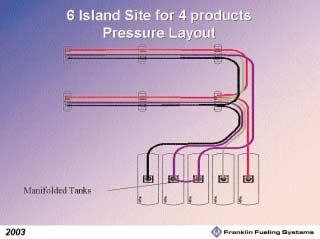
You will see from the layout on page 29 that the amount of pipe and equipment used in a suction system far exceeds that in a pressure system.
Environmental Considerations
Pumping units and piping runs
Suction System Pressure system
12 pumps 3 pumps 12 motors 3 motors 12 air eliminators 3 air eliminators 12 pumping units 3 pumping units 12 pulleys/ belts 0 pulleys / belts
Suction System Pressure system
1 pipe run per unit 1 pipe run per grade 12 units= 12 piping runs 3 grades 3 piping runs
You will see from the above tables that there is a clear economic advantage in building service stations using a pressure system with 75% less piping delivering the same product to the customer. There is sufficient saving in the
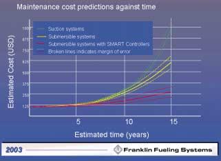
There is also clear evidence that the savings do not stop there with even greater savings being made on the maintenance of equipment. Using pressure technology means there are less motor/pumping systems working at the station. Less moving parts to break down means lower maintenance costs. Experience has shown that failure of submersible pumps is extremely rare. They have a proven track record with excellent reliability and reduced down time, one of the reasons for this is that they operate inside the tank in ideal conditions, submersed in fuel, which cools and lubricates the motor. There is the added bonus of reduced energy costs, which also contributes to increased profits.
As an ex regulator I had concerns as to the past performance of pressure systems in an environment where leaks frequently occurred, and with the that in mind the industry has certainly responded over the years to meet those challenges offering both new materials and technology to reduce this risk considerably. The use of unprotected single wall steel pipe work, which historically caused such horrific leak problems for service stations all over the world, is thankfully a thing of the past. Engineers constructing service stations using pressurised systems at this present time have such a wide choice of non-metallic pipe work suitable for operating at high pressure often secondarily contained with built in leak detection devices. The sophistication of mechanical and electronic line leak detection systems supplied with the submersible pumping system enable lines to be automatically tested for substantial leaks (12 litres per hour) operating each time the pump stops and the delivery cycle ends. In more sensitive environments lines can be checked to a finer test (0.38 litres per hour), at predetermined intervals. These tests only form part of the whole systems, often secondarily contained, and designed to keep the pressure pumping system operating safely and efficiently in any environment.

Tank Remedial Modification Part Three
By Ray King, Director of King Tanktechnic Ltd To line or not to line
Continuing on from part two "The virtues of tank lining against replacement" onto "Which system is right for me?" and how to select the system and the specialist installation contractor.
Leaking Perforated Tanks
In the event of a leaking perforated tank the selection of the remedial lining shall be made in full agreement with the Petroleum Enforcement Officer (P.O.)
There are over 100 different authorities throughout the UK interpreting the rules of guidance and some will only accept a Double Skin system given the failsafe properties of this system with its continuous leak detection control.
Others will accept a Single Skin system which relies totally on the integrity of the finished lining. This acceptance would only be given after documented proof is available on the structural strength of the lining system prior to undertaking the remediation.
The full risk assessment, inspection and report on the donor tank is all part of the build up of documentation required before any lining, Single or Double, can be carried out.
Selection
Single Skin systems are the most cost effective way of upgrading tanks and extending their life without major infrastructure modification. In Canada and the USA many thousands of tanks have been lined using Single Skin systems.
Double Skin systems are the only systems which incorporate continuous monitoring of the interstitial space, giving a visual and audible alarm in the event of leaks to the secondary containment lining or the donor tank body.
Both Single and Double skin systems use a standard procedure in that the donor tank is blasted, repaired and lined using the materials the selected system has approval for. The exception to this is the Bladder inliner which is not a structural system and is fabricated from soft material and can only be inserted into tanks which are classed as tight or have had a remedial Sin le Skin lining installed. A vacuum is required to hold the Bladder inliner to the donor tanks wall. This vacuum is pulled as part of the system control.
Approvals
All systems shall be fully approved by an independent European test house or, if the technology is imported from America, by the U.L. (Underwriters of America or Canada).
Any leak detection control apparatus shall have both visual and audible alarms and give continuous monitoring 24 hours a day, 365 days a year and shall be approved to a European Norm (EN) standard.
Within the above approvals lining materials shall be tested to confirm suitability to given chemical resistance to all present and future fuels. It is essential that future fuels are taken in account due to the ever changing composition of these fuels using Toluene, Methane, Iso-octane and Iso-butane etc., and the lining shall have full electrostatic protection to avoid static build up.
The P.O. shall consider all approvals and also take into account the lining installers work procedure protocol, which shall include quality control measures undertaken and recorded. The P.O. would issue a letter of approval or a letter of 'no objection' to use the system prior to work starting.
The Directors of King Tanktechnic Ltd (KTL) have installed most of the available lining systems.
Firstly undertaking linings using Polyester systems on crude oil storage tanks in Saudi Arabia in 1983 and have progressed through to Vinyl-esters and Bladder inliners before finally selecting the "ADISM' solvent free epoxy system and gaining an exclusive installation contract for the UK and Ireland. The final decision was based on the installation safety factors of the system in relation to the Control Of Substances Hazardous to Health Regulation 1994 (COSHH) and the Approved Code Of Practices (ACOPs) and the extensive research development and approvals of the system. ADISA selected KTI, because of our experience and availability of in-house equipment and personnel trained in lining applications.
The ADISA-KTI, tank lining systems have been used for over 20 years in Switzerland, Germany, Belgium, Spain, France Austria, Italy and the Middle East and are continuing to contain many millions of litres of stored petroleum and chemical products. The expected life span of the lining is in excess of 25 years.
The system can be used on large flat bottom tanks, (see main photo) underground cylindrical storage tanks and has a full European approval. In addition, KTI, have further tested the Single Skin system to destruction to prove the structural qualities for remediating perforated leaking tanks. The documented proof of this test recorded a pressure to burst the lining through 1mm diameter perforations was 300 bar and through 10mm diameter perforations was 50 bar which equated to 3060mt head of water to 510mt head of water. The maximum Hydrostatic external pressure on an average underground petrol tank with groundwater to the top would be 0.5 bar. The structure of the lining is more than capable of withstanding any external pressure exerted to it.
Selection of your specialist contractor
It is essential that your lining contractor is able to prove to you with documented evidence that he has the capability to perform the works with experienced and certified personnel. He shall have all the specialist plant and equipment, have a completed lining reference list for referral and the system he proposes shall have independent approvals to demonstrate that the lining has the chemical resistance compatible to the intended fuel storage, including future fuels. The expertise of the lining contractor and his quality control protocol procedure is the only way to ensure your capital investment will not fail due to bad workmanship.
Beware of 'professional amateurs' who can only talk a good job!
Raymond King Director of King Tanktechnic Ltd Tel: 0161 371 5333 Mr King has over 40 years experience working as an engineer on tankage projects in the UK, Europe and the Far and Middle East on both downstream and upstream operations.
Perforations due to dipstick erosion. Note striker plate not affording any protection Perforations due to dipstick erosion. Note striker plate not affording any protection
Implications of DSEAR on Autogas Installations
By Richard Wigfull, John Wigfull & Co. Ltd
Richard Wigfull is a Chartered Engineer working for the family run business of John Wigfull & Co. Ltd., near Leicester. The Company specialise in the handling of flammable liquids and gases. In addition Richard is associated with the technical management Committee of the LPGA (Liquefied Petroleum Gas Association) and is one of the presenters of the APEA LPG courses. This is a personal view by Richard Wigfull (wigfullr@btopenworld.com) on how the new Dangerous Substances and Explosive Atmosphere Regulations (DSEAR) affect both existing and new LPG installations.
Introduction
Dangerous Substances and Explosive Atmospheres Regulations 2002 impose requirements for the purpose of eliminating or reducing risks to safety from fire, explosion or other events arising from the hazardous properties of a "dangerous substance" in connection with work.
The requirement of the Regulations are for employers and the self employed to:
· Carry out risk assessment of any work activities involving dangerous substances
· Provide technical and organisational measures to eliminate or reduce as far as reasonably practicable the identified risks
· Provide equipment and procedures to deal with accidents and emergencies
· Provide information and training to employees
The Dangerous Substances and Explosive Atmospheres Regulations (DSEAR) apply to all LPG installations.
LPG installations have one significant advantage over most other fuels. They are already designed to operate under pressure and therefore are basically closed systems.
For installations prepared and installed to all current Regulations there should be no significant changes.
Zoned (classified) areas
A lot of emphasis has been placed on formalisation of the electrical part of any installation and this is based around the probability of there being a flammable atmosphere. Hazardous areas are classified in terms of zones on the basis of the frequency and duration of the occurrence of an explosive atmosphere.
Zone 0, Zone 1, Zone 2 unclassified/safe.
Zone 0
A place in which an explosive atmosphere consisting of a mixture with air of dangerous substances in the form of gas, vapour or mist is present continuously or for long periods or frequently.
Zone 1
A place in which an explosive atmosphere consisting of a mixture with air of dangerous substances in the form of gas, vapour or mist is likely to occur in normal operation occasionally.
Zone 2
A place in which an explosive atmosphere consisting of a mixture with air of dangerous substances in the form of gas, vapour or mist is not likely to occur in normal operation but, if it does occur, will persist for a short period only.
By implication, an area that is not classified Zone 0, 1 or 2 is deemed to be a non-hazardous or safe area in respect to the selection of apparatus.
Ø BSEN 60079-10, Classification of Hazardous Areas, provides detailed considerations on the types of protection that may be necessary to achieve safety.
Under normal operations at Autogas installations there are only three sources of release of LPG.
The first two are under the control of the tanker driver when he delivers into the bulk storage vessel.
The third source is on completion of filling the vehicle when the user releases the nozzle latch.
By using standard methodology it can be proved that the zoned areas are very limited. This can be compared with the generic distances used in the current Codes. However continuing to use the generic zones would not be practical because; a) they are not true zones and b) blanket designation of zone 1 would restrict the activities allowed in that area.
Zoned areas should not be confused with separation distances, which are distances from major components to specified features and are primarily to protect the components from external affects. e.g. fire.
Electrical installations
The APEA Blue Book has some information on wiring for Autogas installations and there is a revision started for the electrical requirements for alternative fuels. The LPGA has prepared Technical Memorandum 76 to cover electrical installations for non-forecourt installations. In addition EEUMA have published their useful publication No. 186; "A practitioner's handbook - Electrical installations in potentially explosive atmospheres."
Display of EX sign
Because the LPG releases are small and the likelihood of ignition extremely low provided that appropriate precautions are taken the EX sign need not be displayed.
The precautions include posting and observance of appropriate warning notices, operations and selection of appropriate equipment, also users are aware of the flammable nature of products and the risk associated with the activity is low
However the Regulations cover a much wider range of topics than zoning and electrical equipment.
Non-electrical equipment
One major difference from existing Regulations is the requirement that in zone 0 & 1 areas, non-electrical equipment must be assessed for the potential to generate an ignition source. e.g. due to the rotation of a pump.
Documentation and training
Current Regulations, (e.g Pressure Systems Safety
Regulations and the Provision of Work Equipment Regulations) already require the provision of instructions and procedures to ensure that the installation can be operated safely. This requirement has now been reinforced in DSEAR with Regulation 8 accidents, incidents and emergencies and Regulation 9 information, instruction and training.
Risk assessment and reduction of risk
The Regulations require risk assessments not only for the employees on the site but also "- any other person, whether at work or not, who may be affected by the work carried out by the employer,- "
Good designs and good installation practice should reduce the risks and also protect the site/users against abnormal situations, which could otherwise result in leakage.
As a Company we had already considered this in our designs and some of the features included are;
Protection against release in the event of a vehicle driving away whilst still connected by the fitting of a hose pull-away connection. Whilst there is a variety of information on the types of pullaway fittings there was little information on hose strengths. Tests were carried out on a rig in our yard to confirm hose strengths both for tanker and dispenser hoses.
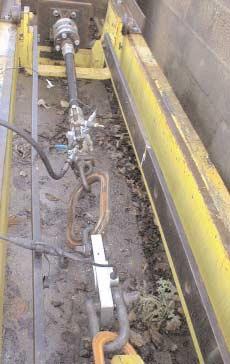
Hose Test Rig
Protection against loss of product in the event of impact of a vehicle on the dispenser by the correct installation of shear valves on the flow & return pipework.
Installation of suitable remotely operated isolation valves at each end of both the flow and return underground pipework. To protect the dispenser valves from damage to the dispenser due to fire or impact these isolation valves are in a chamber separate from the dispenser.
Shear Valves

Dispenser Shut off
4t vessel and pump
Operation of the forecourt emergency shut down system or a fire in the dispenser would close these valves.
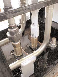
The connections on the 4t vessels we have designed have actuated isolation valves
operated from the same supply as the pipework valves.
In addition the excess flow valve before this valve is mechanicallyseparated from the isolation valve so that in the event of mechanical damage the excess flow valve should not be affected. The drain is a compact valve and all other connections into the vessel have internal pipework ending in
The above design features assist the installation to conform to the requirement in the Regulations that "in the event of the operation of the emergency shut down system any accumulated energy must be dissipated as quickly as possible or isolated so it no longer constitutes a hazard."
Training of contractors
DSEAR reinforces the requirements of the Provision and Use of Work Equipment Regulations, which requires "every employer to ensure that where work equipment is likely to involve a specific risk, the use of that equipment is restricted to those persons given the task of using it and repairs, modifications maintenance or servicing that work equipment is restricted to specifically designated persons whom the employer must ensure have received adequate related training."
Maintenance
Under the existing Pressure Systems Safety Regulations, there are already maintenance
LPG with nitrogen
Shared ownership
Many installations have shared ownership. e.g. the vessels being owned by the gas supply company and the remainder of the installation being owned by the operator. Regulation 11 now puts the responsibility for the implementation of the regulations onto the employer on the site.
Transitional arrangements
There are transitional provisions but these do not apply to the complete Regulations.
Regulations 15(2) Fire Certificates and similar regulations plus repealing of certain regulations came into force on 5th May.
Regulation 5(4) (c) Risk assessment for five or more employees to include zoning, 7 Classification of zones, 11 Duty of co-ordination, and 17 (1) to (3) transitional arrangements come into force on the 30th June 2003.
The transitional arrangements only apply to regulations 7 (Places where explosive atmospheres may occur) & 11 (Duty of co-ordination) for installations, which are in use before 30th June 2003 when the requirements have to be met no later than 30th June 2006. In the event of any modifications then the modifications have to comply fully with the Regulations and also be risk assessed before being carried out.
Additional information
Over the next few months the HSE will be issuing Approved Codes Of Practices (ACOPs) plus the LPGA will issue revisions to their relevant Codes.
Innovative Pressure/Vacuum Vent Valves
By Mr Grahame H Platt, Managing Director, Envirotech Products Limited
Envirotech Products Limited has developed a range of Pressure/Vacuum vent valves for road tanker and forecourt tank use (see Figs. 1&2). These valves are extremely accurate in operation, making use of magnets mounted in the valve plunger to control the opening pressure (Fig. 3). A European Patent has been granted in respect of a feature of the Road Tanker Valve, and applications are being processed for other features of the Valve systems. The essence of the operating principle is that the closer a magnet is to an attracting surface, the greater the force experienced by the magnet. In the case of the Envirotech valve therefore, the pressure trying to open the valve is opposed by the magnetic force holding it closed until these two forces are in balance, after which a tiny increase in pressure will cause the valve to open. By carefully
setting the gap between the magnet and the attractive surface, it is therefore possible to simply but accurately set the pressure at which the valve relieves. One particular benefit of the use of magnets is that as the valve begins to move open, the attracting magnetic force starts to reduce and so the valve accelerates to a wide open position to permit rapid release of the vapours causing the Fig. 1 Forecourt Valve pressure increase. As the valve moves from closed to wide open over a very small pressure range, this means that the relief pressure can be set at the high end of any permissible range thus preventing the slow release of vapours over a wide range of pressures.
Fig. 2 Road Tanker Valve
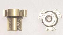
Fig. 3 Valve Plunger and Magnets
As time has gone on, the valve systems have undergone a programme of continuous development. One such major development has been the ability to test the valve for Pressure and Vacuum relief setting whilst the valve remains in place, and in the case of the road tanker valve, to also check the effectiveness of the overturn seal.
A further benefit of the fittings developed to permit testing of the road tanker valve in-situ is that by means of the same fittings, leakproofness and pressure testing of the complete road tanker compartment can be carried out much more quickly and in full compliance with the higher test pressures required following the anticipated introduction of ADR 2003. (See Fig. 4) A further development of the road tanker valve has resulted in a fitting that enables the fuel to be drained from the vehicle in the event of an overturn and without any spillage, thereby reducing the pollution risk. This is achieved by draining through the body of the valve. (See Fig. 5)
Over a period of time, following the introduction of vapour recovery, a number of incidents have been recorded which have taken place during the delivery of fuel at the forecourt. One possible common denominator of some of these incidents has been the fact that the vapour pressure in the tanker being potentially much higher than that on the forecourt, can give rise to an overpressurising of the forecourt system when that system also has other faults (Tanker pressure relief settings are nominally 100 mbar whereas the forecourt relief pressure is 35 mbar). Incidents of this nature were described at an Institute of Petroleum Conference in Wolverhampton in September 2001 (Reference 1). Further details can also be found on the Institute of Petroleum website.
One solution to these problems has been to provide a second line of protection for the forecourt by installing a further vent valve on the road tanker vapour recovery system, but set to relieve at the lower forecourt relief pressure of 35 mbar. Envirotech has developed such a valve - The Interlocked Coaming Dump Valve. (See Fig. 6)
The core of this valve is the valve plunger assembly from the Envirotech Forecourt Pressure Vacuum Vent Valve. T h e pressure relief element is set a 35 mbar as the Forecourt Valve, but the vacuum relief is set at -20 mbar as is the tanker compartment P/V valve (not -2 mbar as the forecourt valve). The vacuum relief via the Coaming Dump Valve is available at all times, but the pressure relief element is locked shut at all times except when the tanker is discharging product at the forecourt. This interlock is pneumatically operated from the vehicle systems. Two reference signals are required to indicate the tanker condition. One of these will be a signal from the tanker vapour recovery adapter to indicate that the vapour recovery hose is connected. However this will arise whether the tanker is loading or unloading. A second signal is therefore required indicating that the tanker is loading and that will probably be a pneumatic signal from the Overfill Protection System.
The circuits are so arranged that with a pneumatic signal from the vapour recovery adaptor plus a pneumatic signal from the Overfill system, the vehicle is obviously loading and there is no signal to the coaming dump valve which remains locked out preventing any release of V.O.C.'s on the loading gantry.
On the garage forecourt, these is only a signal from the vapour recovery adapter which is fed to the Coaming Dump Valve interlock which then withdraws. The pressure relief element of the valve is now free to relieve any excess pressures above 35 mbar when the driver opens the vapour recovery vents from the compartments to the tanker coaming and if for any reason they are not relieved by the forecourt systems.
Whilst the Coaming Dump Valve will help minimise the risk of incidents during vapour recovery, it should not be regarded as a substitute for good maintenance and regular testing of forecourt systems.
Ref. 1 Improving Safety in Petroleum Distribution Learning Lessons from Vapour Recovery Incidents by Alec O'Beirne PTF Training Limited.
Fig. 4 Road Tanker Valve with Test Fittings Fig. 5 Roll-Over Drain Off System Fig. 6 The Interlocked Coaming Dump Valve
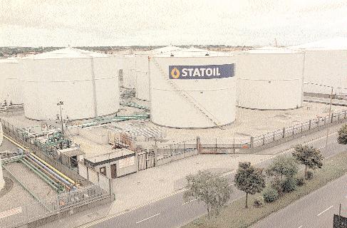
Spotlight on Statoil Ireland Limited
By Brian Baker
Of Norwegian origin, Statoil ASA, founded in 1972, is one of the world's largest oil companies and a significant supplier of natural gas to Europe. Currently active in 25 countries, Statoil is renowned for innovation, quality and high standards in both its products and service to customers while protecting the environment and nurturing relationships with local communities.
Statoil in Ireland
Statoil's operations in Ireland comprise Statoil Ireland Ltd and Statoil Exploration (Ireland) Ltd while the company is increasingly involved in marketing natural gas. The Statoil Group headquarters is in Dublin.
The retail and marketing company, Statoil Ireland, has been in the Republic of Ireland since 1992 when it acquired BP's service station network. Four years later it strengthened its position with the acquisition of Conoco JET retail and commercial operations.
Today, Statoil is the leader in petrol retail, home heating oil and commercial fuels markets. Statoil Ireland now employs over 1,200 people in the Republic, and has a strong community presence through its 300-strong Statoil service station network and its innovative Fareplay forecourt convenience stores.
Statoil has achieved its position as No.1 in the fuel retail market through innovation and competitive pricing and now is the most popular brand with motorists, home-owners and industrial users in Ireland.
Statoil carried out a major rebranding programme of the service stations that it acquired in 1992, setting standards in forecourt design.
In April 2003, the APEA ran a course on Wet Stock Monitoring in Dublin. This was supported by Statoil Ireland Limited sending 17 delegates and Dublin City Fire Brigade sending two.
To deliver this course, a certain amount of research was necessary to understand the Retail Petrol Filling Station market in the Republic of Ireland as well as establishing the technical aspects of building and operating sites. Across several telephone and e-mails, I was able to 'interview' Michael Nyland, Project Engineer with Statoil and here are the results;
(BB) Michael, in Ireland, how many retail petrol stations are there? (MN) The latest information from Mintel (UK) is that there were 3,185 sites in 2000 that serves a population of around 4 million people.
(BB) How many sites does Statoil
have? (MN) 280 of which 66 are Company Owned-Company Operated (CoCo)
(BB) In Ireland, the principal legislation controlling petrol filling stations is
Statutory Instrument 311, of 1979, known as The Dangerous Substances (Retail and Private Petroleum Stores) Regulations 1979, that requires each site to be licensed. It also limits the size of storage tank to a maximum of 40,000 litres. Do Statoil comply with this? (MN) Yes we do. (BB) Are any of your sites Driver Controlled Delivery types? (MN) In Statoil we have none; all are Licensee Delivery Controlled, however we are looking at this option.
(BB) Do you have any LPG (Autogas) on your sites? (MN) There are none on CoCo sites but there are some on dealer sites
(BB) In percentage terms, are any sites still using dip sticks to measure stocks? (MN) On CoCo sites there are none but there may be a few dealer sites.
(BB) Do Statoil favour pressure or suction pumping systems? (MN) About 10% of our CoCo sites operate pressure systems.
(BB) Do Statoil operate Remote Stock Monitoring of sites? (MN) No, not at present, but we are reviewing this option presently.
(BB) In Ireland, how often are Petroleum Licences issued to petrol filling stations? (MN) Most authorities issue 3 year licences. However some authorities issue a one year licence depending on the conditions attached to the licence.
(BB) How many new or raise/rebuild sites have Statoil carried out in the last 2 years?
(CC) In the last two years Statoil have carried out 10 raise & rebuilds in the CoCo network with numerous shop developments. We have also carried out various minor forecourt