3 minute read
Response to Abrupt Maneuvers
from NASA Technical Reports Server (NTRS) 19870001427: Design and fabrication of the NASA decoupler pylon
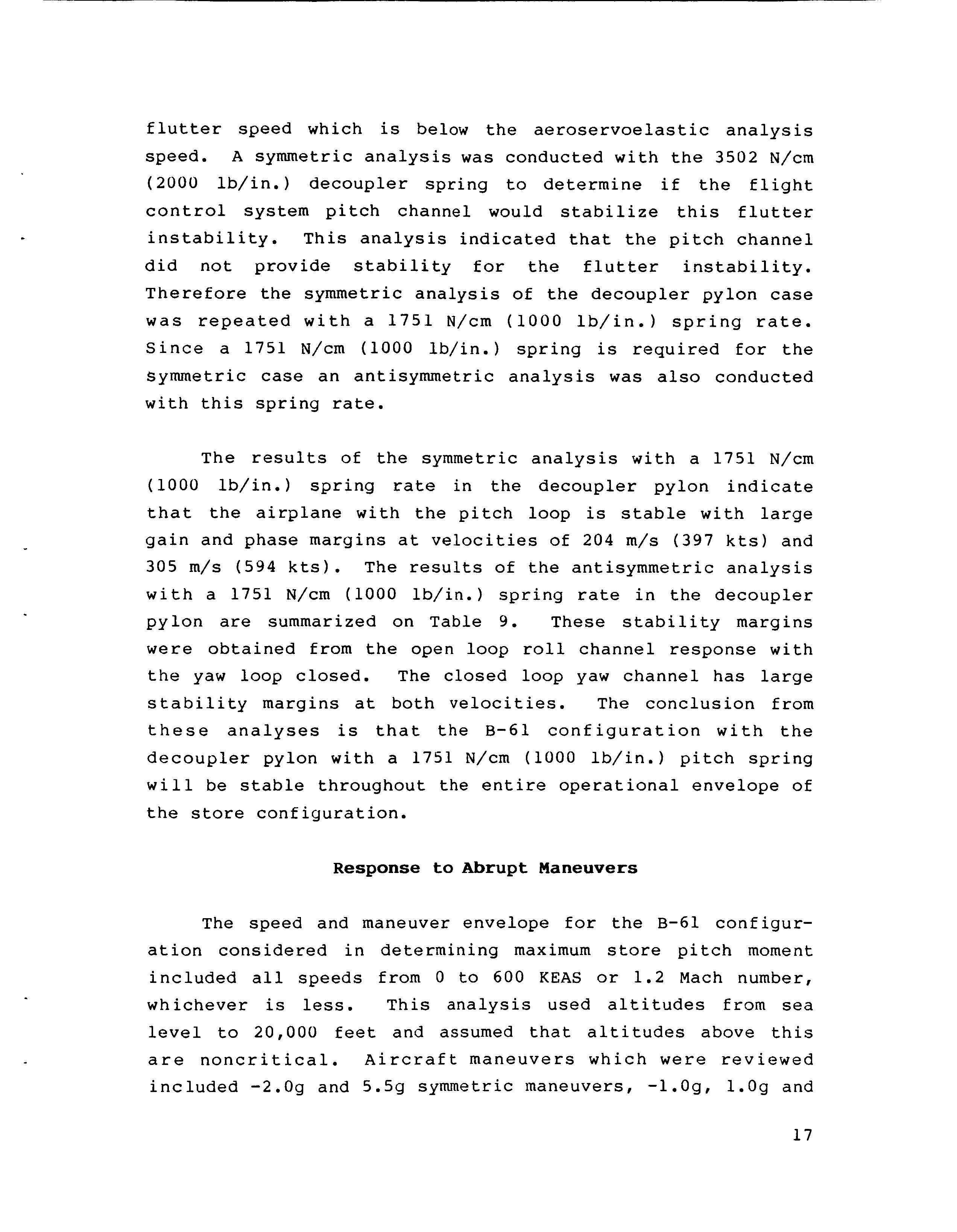
flutter speed which is below the aeroservoelastic analysis speed. A symmetric analysis was conducted with the 3502 N/cm (2000 lb/in.) decoupler spring to determine if the flight control system pitch channel would stabilize this flutter instability. This analysis indicated that the pitch channel did not provide stability for the flutter instability. Therefore the symmetric analysis of the decoupler pylon case was repeated with a 1751 N/cm (1000 lb/in.) spring rate. Since a 1751 N/cm (1000 lb/in.) spring is required for the symmetric case an antisymmetric analysis was also conducted with this spring rate.
The results of the symmetric analysis with a 1751 N/cm (1000 lb/in.) spring rate in the decoupler pylon indicate that the airplane with the pitch loop is stable with large gain and phase margins at velocities of 204 m/s (397 kts) and 305 m/s (594 kts). The results of the antisymmetric analysis with a 1751 N/cm (1000 lb/in.) spring rate in the decoupler pylon are summarized on Table 9. These stability margins were obtained from the open loop roll channel response with the yaw loop closed. The closed loop yaw channel has large stability margins at both velocities. The conclusion from these analyses is that the B-61 configuration with the decoupler pylon with a 1751 N/cm (1000 lb/in.) pitch spring will be stable throughout the entire operational envelope of the store configuration.
Advertisement
Response to Abrupt Maneuvers
The speed and maneuver envelope for the B-61 configur- ation considered in determining maximum store pitch moment included all speeds from 0 to 600 KEAS or 1.2 Mach number, whichever is less. This analysis used altitudes from sea level to 20,000 feet and assumed that altitudes above this are noncritical. Aircraft maneuvers which were reviewed included -2.09 and 5.5g symmetric maneuvers, -1.09, 1.Og and
17
4.49 roll maneuvers with maximum bank angle change of 180°, and 1.09 sideslip maneuvers ranging from maximum positive sideslip angles to maximum negative sideslip angles. The six components of load for each of the maneuvers at 14 Mach/altitude points were computed. These load conditions were searched for maximum and minimum store only pitch moment.
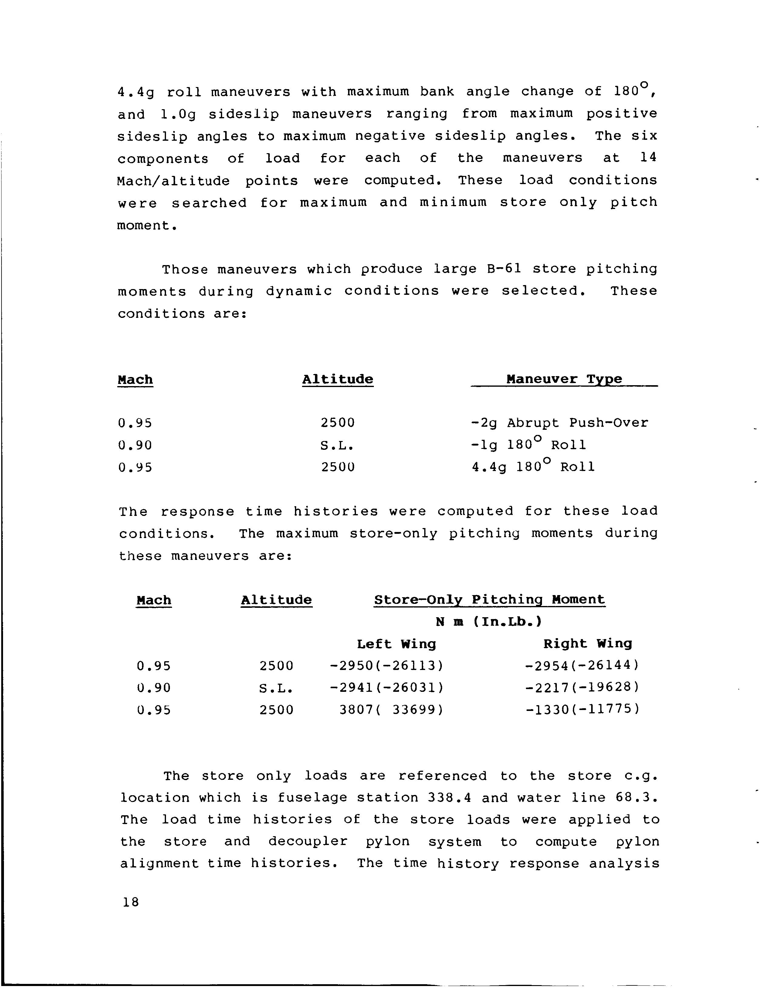
Those maneuvers which produce large B-61 store pitching moments during dynamic conditions were selected. These conditions are:
Mach
0.95 0.90 0.95
Altitude Maneuver Type
2500
S.L.
2500 -29 Abrupt Push-Over -1g 180° Roll 4.49 180° Roll
The response time histories were computed for these load conditions. The maximum store-only pitching moments during these maneuvers are:

Mach Altitude Store-Only Pitchinq Moment N m (In.Lb.1 Left Wing Right Wing
0.95 2500 -2950(-26113) -2954 (-26144) 0.90 S.L. -2941(-26031) -2217(-19628) 0.95 2500 3807( 33699) -1330(-11775) The store only loads are referenced to the store c.g. location which is fuselage station 338.4 and water line 68.3. The load time histories of the store loads were applied to the store and decoupler pylon system to compute pylon alignment time histories. The time history response analysis 18
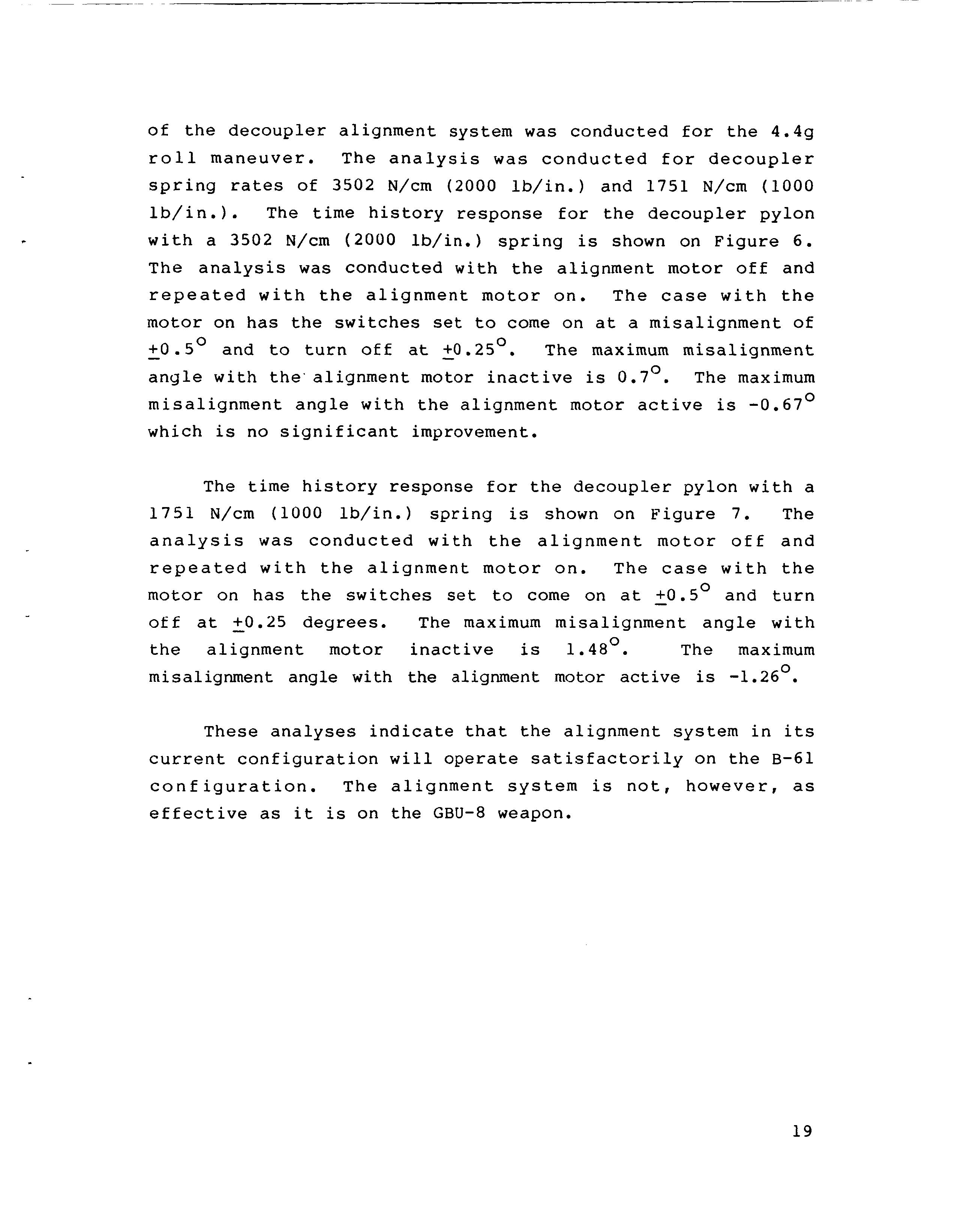
of the decoupler alignment system was conducted for the 4.4g roll maneuver. The analysis was conducted for decoupler spring rates of 3502 N/cm (2000 lb/in.) and 1751 N/cm (1000 lb/in.). The time history response for the decoupler pylon with a 3502 N/cm (2000 lb/in.) spring is shown on Figure 6. The analysis was conducted with the alignment motor off and repeated with the alignment motor on. The case with the motor - +0.5O on has the switches set to come on at a misalignment of and to turn off at 50.25 . The maximum misalignment 0 angle with the'alignment motor inactive is 0.7O. The maximum misalignment angle with the alignment motor active is -0.67O which is no significant improvement.
The time history response for the decoupler pylon with a 1751 N/cm (1000 lb/in.) spring is shown on Figure 7. The analysis was conducted with the alignment motor off and repeated with the alignment motor on. The case with the motor on has the switches set to come on at - +O.SO and turn off at - +0.25 degrees. The maximum misalignment angle with the alignment motor inactive is 1.48O. The maximum misalignment angle with the alignment motor active is -1.26O.
These analyses indicate that the alignment system in its current configuration will operate satisfactorily on the B-61 configuration. The alignment system is not, however, as effective as it is on the GBU-8 weapon.
19


