4 minute read
Flutter Analyses
from NASA Technical Reports Server (NTRS) 19870001427: Design and fabrication of the NASA decoupler pylon
Flutter Analyses
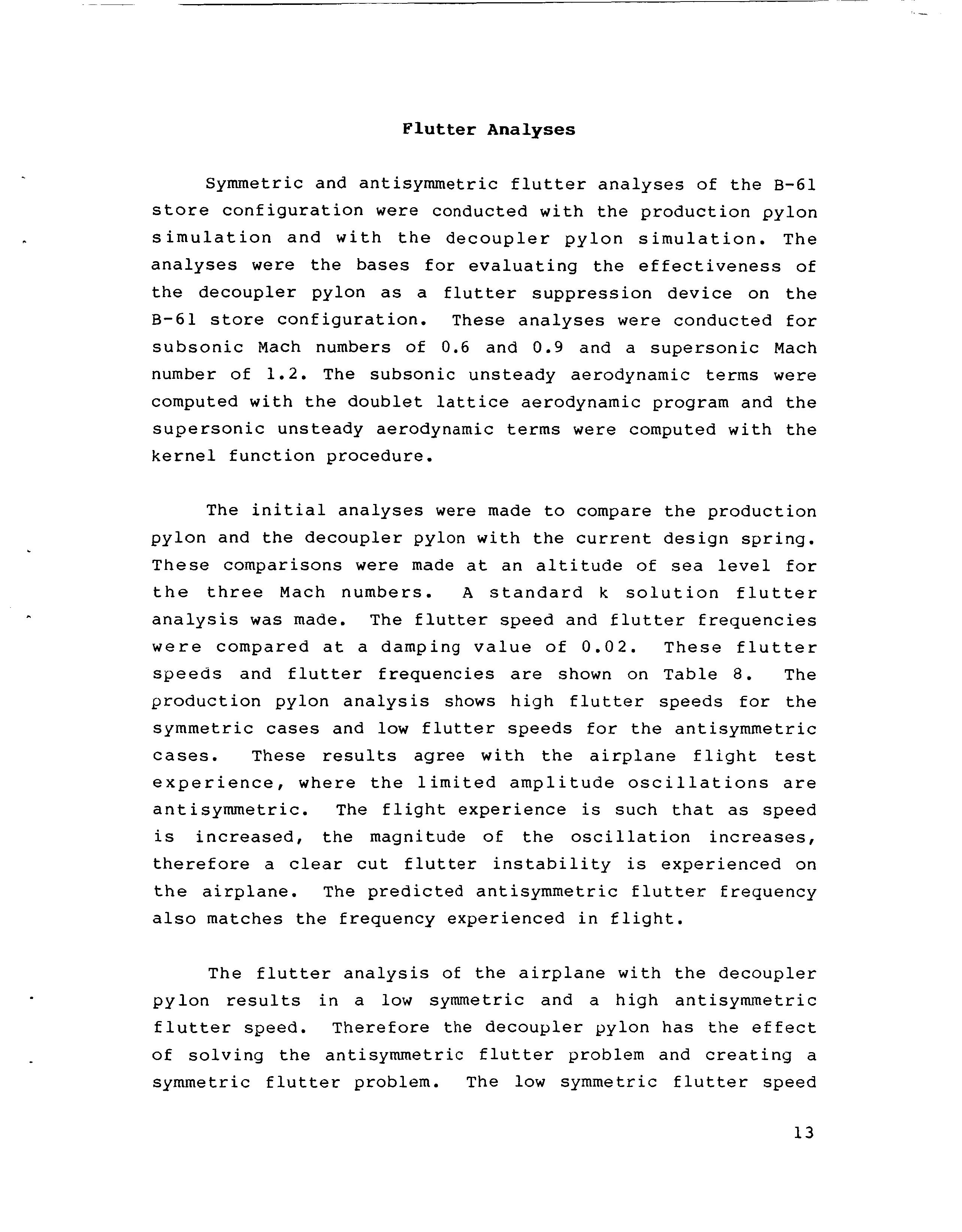
Symmetric and antisymmetric flutter analyses of the B-61 store configuration were conducted with the production pylon simulation and with the decoupler pylon simulation. The analyses were the bases for evaluating the effectiveness of the decoupler pylon as a flutter suppression device on the B-61 store configuration. These analyses were conducted for subsonic Mach numbers of 0.6 and 0.9 and a supersonic Mach number of 1.2. The subsonic unsteady aerodynamic terms were computed with the doublet lattice aerodynamic program and the supersonic unsteady aerodynamic terms were computed with the kernel function procedure.
Advertisement
The initial analyses were made to compare the production pylon and the decoupler pylon with the current design spring. These comparisons were made at an altitude of sea level for the three Mach numbers. A standard k solution flutter analysis was made. The flutter speed and flutter frequencies were compared at a damping value of 0.02. These flutter speeds and flutter frequencies are shown on Table 8. The production pylon analysis shows high flutter speeds for the symmetric cases and low flutter speeds for the antisymmetric cases. These results agree with the airplane flight test experience, where the limited amplitude oscillations are antisymmetric. The flight experience is such that as speed is increased, the magnitude of the oscillation increases, therefore a clear cut flutter instability is experienced on the airplane. The predicted antisymmetric flutter frequency also matches the frequency experienced in flight.
The flutter analysis of the airplane with the decoupler pylon results in a low symmetric and a high antisymmetric flutter speed. Therefore the decoupler pylon has the effect of solving the antisymmetric flutter problem and creating a symmetric flutter problem. The low symmetric flutter speed
13
is the result of having driven the first two mode frequencies very close together (5.99 Hz and 6.19 Hz). In the antisymmetric case, the decoupler pylon separates the wing bending mode and the store pitch mode frequencies (6.11 Hz and 9.82 Hz). This separation results in an increase in flutter speed.
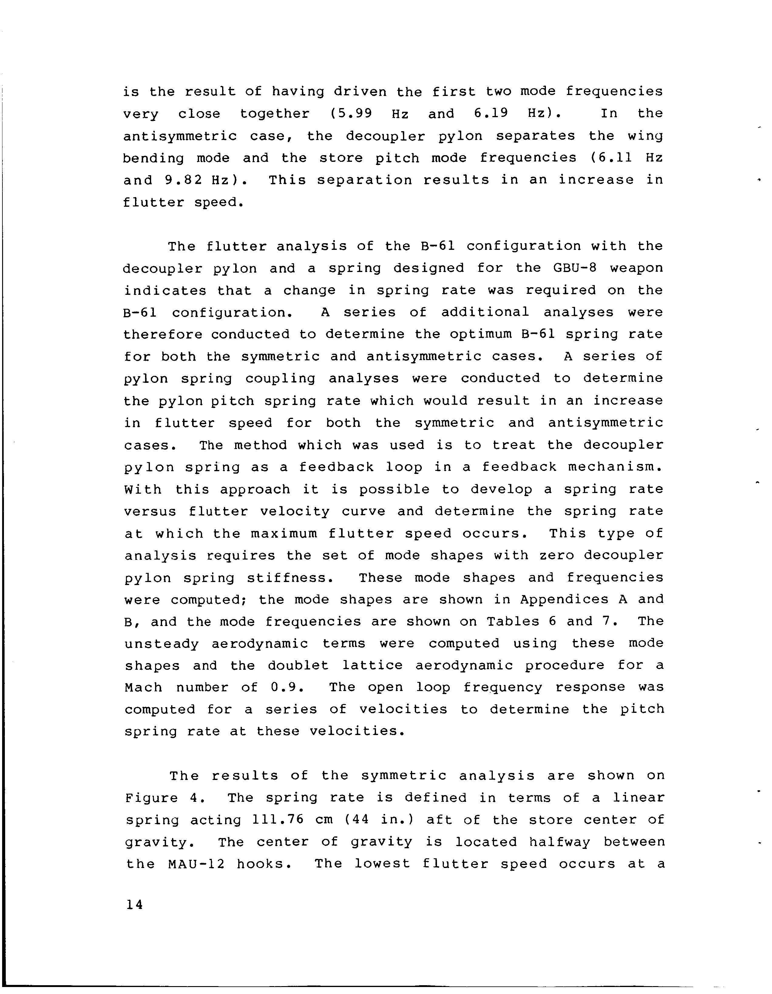
The flutter analysis of the B-61 configuration with the decoupler pylon and a spring designed for the GBU-8 weapon indicates that a change in spring rate was required on the B-61 configuration. A series of additional analyses were therefore conducted to determine the optimum B-61 spring rate for both the symmetric and antisymmetric cases. A series of pylon spring coupling analyses were conducted to determine the pylon pitch spring rate which would result in an increase in flutter speed for both the symmetric and antisymmetric cases. The method which was used is to treat the decoupler pylon spring as a feedback loop in a feedback mechanism. With this approach it is possible to develop a spring rate versus flutter velocity curve and determine the spring rate at which the maximum flutter speed occurs. This type of analysis requires the set of mode shapes with zero decoupler pylon spring stiffness. These mode shapes and frequencies were computed; the mode shapes are shown in Appendices A and B, and the mode frequencies are shown on Tables 6 and 7. The unsteady aerodynamic terms were computed using these mode shapes and the doublet lattice aerodynamic procedure for a Mach number of 0.9. The open loop frequency response was computed for a series of velocities to determine the pitch spring rate at these velocities.

The results of the symmetric analysis are shown on Figure 4. The spring rate is defined in terms of a linear spring acting 111.76 cm (44 in.) aft of the store center of gravity. The center of gravity is located halfway between the MAU-12 hooks. The lowest flutter speed occurs at a
14
spring rate of approximately 3502 N/cm (2000 lb/in. 1, which is the value in the current decoupler design. The results of the v-g solution are also shown on Figure 4 for comparison with the open loop results. The difference in velocity between the v-g solution and the open loop solution is due to small changes in the mode shapes between the finite decoupler spring and the zero spring modes. Structural damping values of 0.02 in the flexible modes were used to predict the flutter velocity in both cases. A softer or a stiffer pitch spring with respect to the current design will result in a higher flutter speed.
The results of the spring coupling analyses of the antisymmetric modes of vibration are shown in Figure 5. The spring rate is defined in terms of a linear spring acting 111.76 cm (44 in.) aft of the store center of gravity. The center of gravity is located halfway between the MAU-12 rack hooks. The lowest flutter speed occurs at the highest spring rate and the flutter speed increases as the spring rate decreases. In the spring rate range from approximately 3502 N/cm (2000 lb./in.) to 10506 N/cm (6000 lb./in.) there is a narrow region of instability and at higher velocities the flutter condition would again become stable. The phenomenon is analogous to a velocity damping solution which crosses zero damping as velocity increases and then with further increases in velocity crosses back over zero damping and becomes stable. At the higher spring rates where the higher velocity stable region does not exist, the damping approaches zero without crossing it. At a spring rate of approximately 5255 N/cm (3000 lb./in.). The unstable velocity region is very narrow. The flutter analysis results obtained with spring coupling were compared with the v-g solution approach on Figure 5 for a spring rate of 3502 N/cm (2000 lb./in.). The small difference in flutter speed between the v-g solution and the spring coupling solution is due to small

15


