14 minute read
Advanced air-fuel and oxygen sensor diagnosis

from Auto Service Professional - January/February 2013
by EndeavorBusinessMedia-VehicleRepairGroup

Time-saving advice on catching the really tough problems
By Alex Portillo
Portillo is the head technician of Car Clinic, a state-of-the-art automotive repair facility in Mahopac, N.Y. He has been trained by Automotive Technician Training Service and is TST certif ed. Portillo’s real-world, in-depth diagnostic articles appear in Auto Service Professional on a regular basis.
Not long ago, Auto Service Professional covered all of the basics concerning how to diagnose common oxygen and air-fuel sensor codes (see the March/April 2012 issue). This time, we are going to discuss more advanced sensor diagnosis so you can catch those really tough problems that are not simply a matter of checking the heater circuit and having a specif cation.
Very brief review
Air-fuel and oxygen sensors work in tandem, before and after the catalytic converter. The PCM compares the readings in order to analyze catalytic eff ciency, and whether the vehicle is running rich or lean.
When the air fuel or front oxygen sensor senses a rich fuel mixture in the exhaust, the PCM takes that information and then tries to do the opposite to make a fuel mixture that is perfect (called “Lambda”) by sending fuel trims in the opposite direction. Air-fuel sensors ref ect a lean condition when their voltage increases and a rich condition when their voltage decreases. Oxygen sensors work the opposite way, with an increase over 450 mV ref ecting a rich fuel
Figure 1: When the air-fuel sensor detects rich exhaust, it reports this to the PCM which then takes away fuel to make the air-fuel mixture normal. This is why rich exhaust creates negative fuel trim and vice versa. mixture and a decrease below that number a lean fuel mixture (see Figure 1).
Post-cat oxygen sensors, when good, feature a steady voltage usually between 500 to 700 mV. If it zigzags, the catalytic converter is highly suspect.
Quick air-fuel sensor check. Are you convinced the A/F sensor is stuck lean or rich, but don’t have the right specif cation? Until advanced milliamp clamps are mainstream where you would be looking for a specif cation of 0 amps (+ or –0.03 mA), you will have to either put a digital multimeter in series hooked up in the amps port. This is time consuming and putting the meter in series between the wrong wires can fry the PCM. A better method is to stick an emissions analyzer in the tailpipe. If the rear oxygen sensor has elevated mV (something in the 800 mV range) and Lambda is rich, you likely have an A/F sensor stuck lean. An A/F sensor stuck rich
Chart and information courtesy DENSO

The vehicle emission control information label indicates what type of sensor(s) is present (A/FS for air/fuel sensor; and H02S or 02S for oxygen sensor).
Fuel trim control exhaust sensors
The exterior appearance of air/fuel sensors and oxygen sensors may be very similar but that’s where the similarity stops. Using a light bulb analogy, the oxygen sensor sends voltage to the engine control unit and acts like an on/off switch, turning the bulb on and off. The air/ fuel sensor receives voltage from the engine control unit and acts like a dimmer switch, making the bulb brighter/dimmer. They differ in output characteristics, so although they may look alike, the two sensor types are not interchangeable.
Vehicles equipped with an air/fuel sensor have approximately 0.4 V constantly applied to the sensor which outputs a current that varies in accordance with the oxygen concentration in the exhaust gas. The ECU converts the difference in output current into voltage, allowing a response that is directly proportional to the present air/fuel ratio in the exhaust system.
The air/fuel sensor operates at a temperature of 1,200 degrees Fahrenheit, which is twice that of an oxygen sensor. Lean mixture indicates higher voltage on the voltmeter. Rich mixture indicates lower voltage on the voltmeter.
In vehicles equipped with an oxygen sensor, the output voltage changes in accordance with the oxygen concentration in the exhaust gas. The ECU uses this output voltage to determine whether the present air/fuel ratio is richer or leaner than the stoichiometric air/fuel ratio (14.7:1).
Light-off temperature between 572 degrees F and 752 degrees F is needed to quickly warm up the oxygen sensor. Three- and four-wire oxygen sensors have builtin heaters.
Lean mixture indicates lower voltage on the voltmeter. Rich mixture indicates higher voltage on the voltmeter.
NOTE: For more sensor diagnostic information and your own copy of DENSO’s sensor poster, go to http:// www.densoaftermarket. com/posters/.

is much more rare, but theoretically can be approached in the same way (low rear oxygen sensor voltage and lean Lambda).
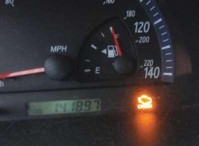
Tough P003X oxygen sensor codes. You get an oxygen sensor code, the repair is almost always an oxygen sensor, right? Well, if you have a code in the P003X (X equaling 1 through 9) range, you should expect that the vehicle has the wrong sensor or a module Figure 2: 2003 Toyota Camry with a P0031. problem. This can be best illustrated in a case study. We received a phone call from a local shop about a 2003 Toyota Camry 2.4L four cylinder 2AZ-FE California emissions vehicle with a strange P0031 Oxygen Sensor Heater Control Circuit Low B1S1 (see Figure 2). This is how the story goes:
They get a “heater circuit DTC,” probably a different code number, checked the sensor and it had an open circuit. A new sensor from the dealer was ordered and installed into the vehicle, but the light stayed on. The resistance of the new sensor’s heater circuit appeared good, and the PCM was duty cycling the heater circuit nicely, which conf rms the integrity of the wiring. The shop and all of its mechanics were stumped and decided to put a computer in it.
That’s where we come in. We were paid to reprogram the keys to the new PCM and when we did the check engine light still went on with the same code. Now, we had a diagno

even though this particular code says “oxygen sensor heater circuit,” what they are really talking about is the front A/F sensor. By looking at the wiring schematics, this particular air/fuel ratio sensor is a four wire sensor with two signals wires from the PCM which provide voltage to the sensor. One of these wires is -3.0 (White) and the other +3.3(Orange). The third wire is a heater element circuit (Brown/Red) wire and f nally a battery voltage wire (Brown/ White). The E.F.I fuse supplies B+ to the E.F.I relay which then supplies battery voltage to the A/F sensor heater element when checking the B+ (Brown/White) wire (see
Figure 4). Figure 3: The new PCM still sis on our hands set the same DTC and turned (see Figure 3). on the Check Engine Light. On this vehicle,
Figure 4: Here we have the wiring diagram for the 2003 Toyota Camry’s oxygen sensor heater circuit. Highlighting a wiring diagram often helps us understand what we are looking at easier.

It is necessary to visually inspect fuses and relays nowadays for voltage drops situations. When we began diagnosing this car, we were getting 12 V key on. We also checked the fuse and relay which all tested good, so obviously that’s why we were getting 12 V.
After these checks we pulled out our scan tool to begin looking at PIDs. We noticed that the signal for the A/F sensor was a steady 3.29 V, which indicates almost a perfect air-fuel mixture as per the Toyota specif cation. Coolant temperature was 120
labscope to check the integrity of the wiring and to see if the heater circuit was duty cycling properly.
How do we do this? We check power on the heater circuit from the PCM and at the sensor itself, and look at the difference. A voltage drop between the two can ref ect a wiring or connection issue, while a lack of duty cycling at the PCM or the sensor itself can help us condemn an individual component (see Figure 6).
We did this test by hooking up the labscope to the black/red heater element wire to the air/fuel ratio sensor
control signal duty cycling between 0 to 14 V on our ATS EScope. There was no voltage drop between the two signals, as you can see in the picture, red and yellow are overlapping each other. After we did this reading, it was no wonder why the other shop thought Figure 5: Screenshot from the Toyota Techstream. Look for any suspect PIDs. it was the PCM. degrees F, STFT 0% and LTFT +2%. The fuel appeared to check out, lending plausibility trims were practically perfect, which made to the theory that the PCM had some sort of sense given the A/F sensor data. Everything internal logic error. As we have just shown, seemed normal, but our code did not indiwe had checked everything that was related cate the sensor was not working properly. to this heater circuit problem from check
Instead, we had to dig deeper into why the ing powers and grounds, scan tool PIDs and heater circuit was throwing the code (see using a labscope. Yet, all we proved is that
Figure 5). we had a functioning A/F sensor.
There are only three possible causes. The Then, our patience paid off. We decided to sensor, the wiring, and the PCM. Being that keep the car running and let the labscope it had both a new PCM and sensor from do its thing. Then, all of the sudden, the the dealership, it was time to whip out the heater circuit was not pulsing between 0 Everything and to the PCM E9 connector pin No. Figure 6: The A/F sensor heater circuit being scoped on 4. Then we started up the car and the ATS EScope. The yellow waveform is at the heater circuit itself and the red waveform (overlapped by the did our readings. What we found was yellow one, because there is no voltage drop on this a good PCM pulse width modulated circuit) is directly at the PCM’s heater-circuit driver.


to 14 V! It was just reading a steady 14 V. a fat top. Who was wrong, the dealer or Then, the check engine light turned on. Worldpac? Can you guess why? Our advice? Never trust the parts guy.
The car warmed up and went from open We talked to the other shop’s foreman to loop to closed loop! What the other shop tell him that he had the wrong sensor and was doing during their diagnosis is that he replied, “No way, it’s from the dealer!” they just stopped after taking their readWe told him to humor us and check to see ings. Since the car was allowed to run a if he had two Camrys in the shop in his little longer, we caught this fault. receipts. Less than 15 minutes later he
Let’s take a look at the scan tool when called me just to let me know that it was the car goes off of open loop mode to closed the wrong sensor that they installed in the loop. It shows that at the fuel system No. car! They had a 2005 Toyota Camry that 1 PID is “OLFAULT.” That means the engine needed an oxygen sensor on a future date computer cannot go into closed loop, so the and apparently they grabbed the wrong PCM knows that the heater sensor off the shelf. That’s why circuit element is not being the P0031 came back when the commanded/grounded; but car was about to enter closed the PCM is smart enough to loop. compensate for that issue As you can see in the picture to maintain its fuel strategy the sensors look totally difeven though the A/F sensor ferent from the outside and is not operating as designed. surely the insides are differOLFAULT is another term for ent too, even though they are “LIMP-MODE,” but for fuel Toyota’s Denso sensors. control. See Figure 7. The one on the
Why would the PCM go into left is the correct A/F sensor this mode and not closed Figure 7: The correct A/F and the one on the right is loop? It is almost impossible sensor next to the wrong the wrong one. Notice how the application. that two PCMs would do the A/F sensor has four breather same exact thing and a little too coinciholes and the other only has two? Also, one dental that when the vehicle wants to go is thicker than the other. to closed loop that the sensor would stop One last tip. Unless you have an ohms duty cycling. So we f gured it had to be the spec, do not be too sure that what you sensor. are reading is a “good” heater circuit. The
A brand new sensor?!? The heater circuit right specif cation for this 2003 Toyota element showed 2.8 ohms of resistance, so Camry I4’s A/F sensor is 1.1 ohms while the circuit itself was good. But, if you have the 2005 Camry’s sensor is 2.8 ohms (see a code in the P00 as opposed to the P01 range for the oxygen sensor, suspect that something is confusing the computer.
We went onto Worldpac speed dial to look up the part number and company of the OE sensor for a 2003 Toyota Camry with the same engine with CA emissions.
What we found was that the A/F sensor listed was different from what was on the car. Both sensors were Densos, but the OE sensor on Worldpac had four holes on the bottom and a skinnier top when compared to the one on the car. The car’s A/F sensor Figure 8: The specif cation on a 2005 Camry had only two holes on the bottom and A/F heater circuit in ohms.


Circle 104 on Reader Service Card
2003 Camry A/F heater circuit in ohms.
The lower the resistance, the higher the amperage, so this ECM has been programmed to work and command a pulse width on this heater sensor with higher amperage, but keep in mind that this reading was tem to go into closed loop.
heater element
After we installed the correct sensor we had our scan tool connected to prove a point. When the engine was in open loop the A/F sensor voltage read 3.29 V with a STFT of 0 percent and a LTFT of 6 percent (see Figure 10).
The vehicle warmed up and the PCM went into closed loop and not OLFAULT! That means the vehicle was 100 percent f xed. We tested the sensor by going WOT.
The A/F sensor signal was at 2.35 V at 3,500 RPM (the engine becomes rich because of fuel being dumped into the cylinders) and then the PCM tried correcting itself and cut off fuel sending the A/F voltage to 4.16 V before settling back to 3.29 V.
Also notice how the short fuel trim was
Figure 9: The specif cation for a 2003 Camry A/F heater circuit in ohms. under 10% under load. Figures 8 and 9). Figure 8 is the specif cacontrol in closed loop. tion on a 2005 Camry A/F heater circuit in This same test was performed with the ohms and Figure 9 is the specif cation for a wrong sensor, but there wasn’t any change
taken when the Figure 10. In this Techstream screenshot, the right A/F sensor allowed the sysThis indicates that the PCM is under fuel was cold because that is when the heater on voltage or fuel trims because the ECM element works harder. The hotter the sensor was under OLFAULT (again see Figure 5). gets, the higher the resistance and the ECM Perhaps if we were smarter diagnosticians, detects this and adjusts the pulse width we would have realized that this was not signal in order to get the amperage lower. normal operation, but hey, we had to learn The PCM detected something different than the hard way. what it was designed to work with and set Now that we’ve been through it, you don’t the P0031. have to experience the same grief. ●