31 minute read
Chasing the irritant gremlins

from Auto Service Professional - January/February 2013
by EndeavorBusinessMedia-VehicleRepairGroup

The majority of customers expect a smooth, quiet ride. When noise, vibration or harshness issues arise, a methodical diagnostic approach can pinpoint the root cause.
Noise/vibration/ harshness
Chasing the irritant gremlins
Part one of two By Mike Mavrigian
Ahost of various noise and vibration issues normally exist during the operation of any vehicle. However, when levels of these factors become noticeable to the customer, he or she may perceive any annoying noises and/or vibrations as problems. NVH (noise, vibration and harshness) is the commonly-used term used when discussing these conditions.
In some cases, any noise or harshness complaints may stem from the vehicle owner’s perception, or their expectations of how the vehicle should behave.
The NVH condition that is a concern does not need to be the strongest vibration or the loudest noise. It could be one that has recently developed and was not previously present.
As an example, tire tread noise from a vehicle equipped with large tread block tires might be acceptable to the owner of a 4x4 who recognizes this as a natural by-product, while others may f nd this as totally unacceptable. A complaint on the same vehicle could be much more subtle, caused by a driveline problem.
Because we sense vibration and sound using different senses, we tend to discuss them separately. However, vibration and sound are essentially identical.
A sound is a vibration (pressure f uctuation) of the air. Vibrations and sounds are
Courtesy Toyota

We experience vibration by our senses of touch and vision. We experience sounds by our sense of hearing. People can perceive the same noise and vibration differently. To some it may be annoying, to others merely unpleasant, while others may not notice it until it is pointed out, and even then some may not be able to recognize the issues.
both expressed as waves per second called Hertz (Hz).
Vibrations that are felt are under 200 Hz. Vibrations between 20 Hz – 20,000 Hz are audible by humans. Vibrations over 20,000 Hz are ultrasonic and are not audible by humans.
Vehicles offer three major sources of potential vibration. These include the engine and engine accessories, driveline and wheels and tires. Each of these sources usually rotate at different speeds or frequencies. A component generating a vibration can be associated with one of the source groups if the frequency of the vibration can be determined.
For example, a light truck equipped with an automatic transmission and 31 inch tires, traveling at 50 mph, in overdrive will have an engine speed of 2,050 rpm/34.1 Hz; a driveline speed of 48.5 Hz; and a wheel speed of 10 Hz.
Body shake/steering f utter/shimmy
Body shake, steering f utter and steering shimmy complaints all involve pinpoint diagnosis of the same components. The condition of the component is what determines which of the symptoms occur. The wheels and tires offer a good starting point, especially if the NVH analyzer identif es this area as the generating force of the vibration.
Tire and wheel inspection includes checking all four tires regarding manufacturer, size and specif cations. Proper tire pressure is also an important item to conf rm. Look for damage, deformation and wear. The technician should also rotate the tire and wheel assembly, inspecting both the
Humans are able to detect vibration and sound within a range of frequencies. The outlined area represents that range audible by humans.

sidewall and tread to look for obvious conditions caused by road damage, f at spots or runout. It’s also vital to inspect and feel the tread for unusual wear patterns.
Check the tire and wheel for proper bead seating along the entire bead circumference on both sides. An improperly seated bead will create a radial runout condition.
Check hub-to-wheel centering, to verify that the clearance is even and within the target value of 0.004 in. (0.1 mm) maximum. If the clearance is out of spec, rotate the wheel (wheel clock position relative to the hub). If the clearance is still out of specif cation, check the hub for runout to determine if the condition is in the hub or the wheel.
Beating/phasing growl
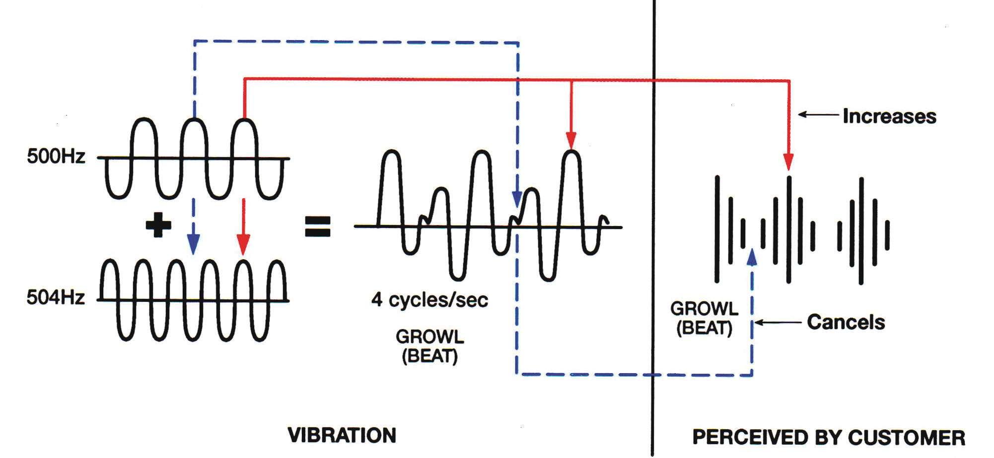
Beating or phasing occurs when two similar vibrations or sounds with slightly different frequencies exist in the same area or vehicle. Over a period of time, the phase of the two waves will change due to the slight difference in frequencies. At times, the two higher points overlap and create an even higher peak which raises the level or amplitude. Also, at times the two low points overlap to make an even lower point which lowers the level or amplitude.
This change in intensity or amplitude occurs in a repetitive manner at a constant vehicle speed as the phase of the wave changes over time. The resulting wave creates a sound called “beating,” which is associated with a vehicle having more than one tire out of balance. Even though the vehicle may feature tires of the same brand and size designation, tires are not always the same diameter during vehicle movement (due to variations such as inf ation pressure and dynamic load), and will rotate at slightly different speeds (Hz). This condition can be corrected by eliminating either one of the vibrations. If one tire is balanced, then the beating noise will be eliminated, leaving the constant vibration from the remaining out of balance tire. Correcting the second tire will return the vehicle to its original condition and ensure customer satisfaction.
A single vibrating force may generate more than one vibration. For example, an out of balance tire can develop multiple vibrations due to the distortion of the tire as it rotates. This is a characteristic of radial tires. The tire is no longer round, and bumps rise on the tire, causing additional vibrations. The distortion of the tire is caused simply by centrifugal force as the tire rotates. Centrifugal force is similar to swinging a yo-yo in a circle. The faster you swing it, the more the pull. This pulling force is what causes the tire to change shape.
As the tire rotates, the heavy spot on the tire causes an up and down motion as it contacts the road. This will induce a vibration into the suspension and steering system, which will be felt by the driver. The centrifugal force of the rotating heavy spot also contributes to the up and down movement.
The vibration caused by the heavy spot is a “f rst order” vibration. It occurs once every revolution of the tire. A f rst order vibration can be the largest amplitude vibration of the vibrations caused by the imbalance. Due to centrifugal force and the heavy spot, the tire changes shape raising additional high spots on the tire. As these spots contact the road, they also cause an up and down motion that is induced into the suspension and steering systems.
This second vibration is caused by a second bump in the tire as a result of the change in shape. It is usually smaller in amplitude than the f rst order vibration. This is called the “second order,” or second component vibration.
Because there are two vibrations in one rotation of the tire, the second order vibration will be approximately twice the frequency of the f rst order and a spike on a frequency analyzer will appear at that frequency.
The third vibration is caused by a third bump as a result of the change in shape. It is generally smaller in amplitude than the second order vibration, though there are some applications and speeds where it may be greater in amplitude than a f rst order vibration. This vibration is called the “third order” or tertiary component vibration. It will appear as a spike on a frequency analyzer at three times the f rst order vibration, due to the three vibrations per revolution of the tire.
Tire RFV (radial force variation)
Tire radial force variation is a key consideration when diagnosing tire-related vibrations that occur at varying speeds and conditions. All OEM wheel assemblies are phase matched to align the tire’s point of maximum RFV with the wheel’s point of minimal radial runout (high point of tire to low point of wheel).
Maximum RFV is generally indicated by a red dot on the tire which should be aligned with the white dot on the wheel (or to a dimple on a steel wheel). The red dot on the tire indicates the tire’s maximum RFV, while the white dot on the wheel indicates the wheel rim’s minimum radial runout point (a dimple on a steel wheel indicates the wheel’s low point). When using alloy wheels, the tire’s red dot should be aligned with the valve stem, as this should be the minimum radial runout point. A third dot, yellow in color, is also featured on the tire sidewall, and indicates the lightest point of the tire (in terms of weight from a balance consideration). A tire’s yellow dot should be aligned with the wheel’s valve stem, which should be the wheel’s heavy spot.
Even if dynamic wheel balance (from a standpoint of weight) is correct, misalignment of the red and white dots will likely result in a vibration complaint. On OEM tires and wheels, always align the red tire dot and the white wheel dot (or valve hole, in the case of alloy wheels) when mounting. If the tire features a red dot and a yellow dot, the red dot is more critical and should be aligned with the wheel’s low point (dimple or valve stem). • Red dot on tire: Align to the wheel’s low-point dimple (steel wheel) or to the valve stem (alloy wheel); or to a white dot on the wheel if the wheel features a white dot. • Yellow dot on tire: Align to the wheel’s valve stem. • Both red and yellow dots on tire: The red dot takes precedence. Align the red dot to the wheel dimple or valve stem.
Radial force variation is a term that relates to a tire-sourced out-of-round/vibration that occurs, and masks itself as an imbalance vibration, only under dynamic conditions... when the wheel and tire package rolls in a loaded state. It must be noted that the term “radial” refers to forces applied at the radius of the tire, not to the type of tire construction. Radial force vibration could potentially occur with any type of tire, regardless of its construction (radial, bias ply, etc.). In other words, a radial force variation may prove to be the cause of a vibration that won’t reveal itself during a static or dynamic balance job, or by checking the mounted tire for runout in an unloaded state.
When a customer complains of a “tire

vibration,” although the root cause may to remove the wheel studs to gain access to simply involve a static imbalance, other facthe hub contact area. Pre-load the plunger tors may be at play, including a static radial slightly and zero the dial. Rotate the hub runout of the wheel and/or tire, a suspenslowly, watching for runout on the gauge. sion/chassis problem, or a dynamic-only If the wheel is lugcentric (where the runout condition, known as radial force wheel-to-hub centering relies on the locavariation of the tire. tion of the wheel fastener holes to the
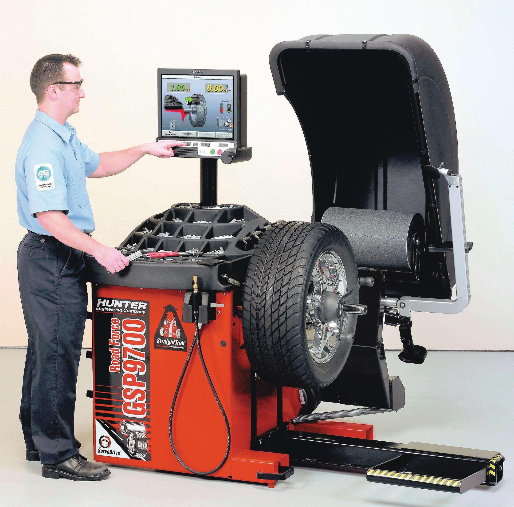
If static imbalance is the culprit, this is hub’s studs only), you can mount the dial easily cured by balindicator so that the ancing the tire/wheel plunger is about .040 assembly. If runout -inch away from the is the cause, this can outer edge of the be cured by replacwheel stud pattern ing the faulty wheel diameter. Using a or tire; or possibly by feeler gauge, check match-mounting the for changes in the tire/wheel package. gap between the dial However, when that indicator plunger approach does not and the outer edge f x the problem, the of the wheel studs technician must begin as you slowly rotate a diagnostic approach the hub 360 degrees. in order to locate the Granted, this can be cause. a time-consuming The best method of determining a mounted and nit-picky job, Inspect for radial tire’s radial force variation is to run the asbut this will either runout sembly on a balancing machine that features recognize the wheel
When a “mystery” a load-force road wheel. The example shown here is Hunter’s GSP9724. to-hub mating as the vibration enters the culprit, or eliminate shop, approach the problem in a systemthis variable from your diagnosis. atic manner to eliminate possible variables. NOTE: Do not use the outer edge of the Naturally, check the tire/wheel assembly brake rotor as your measurement point for balance on your shop’s balancer. If static when trying to check hub runout. You balance is verif ed, begin measuring for must take this measurement at the centerexcessive runout. First check hub runout ing area that the wheel uses, whether this in order to identify or eliminate the hub is the hub (for hubcentric wheels) or the as the possible root cause of the problem. wheel studs (for lugcentric wheels). With the wheel/tire removed from the vehicle, check the runout of the hub. This Checking wheel runout can be tricky because of clearance at the In order to isolate wheel runout on its wheel studs, but can be accomplished with own, dismount the wheel from the tire enough patience. and thoroughly clean the bead seat area.
If the wheel is hubcentric (where the Mount the wheel onto a rotating f xture wheel relies on hub centering at the wheel with acceptable runout (the vehicle hub hub hole to the hub protrusion), you’ll want or on your shop’s balancer, as long as to check the runout of the hub itself, at the your chosen f xture is verif ed for acceptcontact area for the wheel’s center hole. If able runout). Mount the dial indicator to the hub center protrudes far enough from allow the plunger tip to contact the wheel’s the wheel studs, mount the dial indicabead seat area, perpendicular to the seat tor so that the plunger contacts the hub surface. Don’t try measuring runout at the surface. In some cases, it may be necessary outer edge of the rim, as this may have no

bearing on runout — it’s important to check for runout at the area where the tire bead seats, and where the wheel has an effect on the mounted radius shape of the tire.
Preload the plunger slightly and zero the dial gauge. Rotate the wheel a full 360-degrees while monitoring the dial indicator gauge. Again, whenever measuring runout of any rotating part, use of a roller-tipped indicator is always preferred, to avoid snags and bumps that can be encountered with a non-roller tip plunger. If runout is beyond acceptable tolerance, the wheel may require replacement. However, once you f nd the low spot of the wheel’s runout, mark this and remount the tire, matching the high spot of the tire to the low spot on the wheel. Balance the assembly and road test. If the problem vibration was indeed a case of wheel and tire combined runout, match-mounting may solve the problem.
Understanding the severity of loaded tire runout
As a general rule-of-thumb, a minimum range of between .3 to .5 ounce (7 to 14 grams) of imbalance is usually enough for the average motorist to notice an imbalance-induced vibration. If a vehicle is sensitive enough to exhibit noticeable vibration at only .3 to .5 ounces of imbalance, that same amount of vibration may be present with as little as 10 to 15 pounds of radial force variation, which (although hard to believe) can be caused by as little as .010-inch to .015-inch of loaded radial runout. Using this as an example, it’s easy to see how loaded runout can dramatically affect vibration. In other words, a little bit of “loaded” tire runout variance can make a big difference in terms of operating smoothness or harshness.
Don’t automatically blame the tires
While a customer may be quick to place any vibrational problem with the tires, or your handling of those tires, we need to remember that many other variables are potentially involved, any one of which could be the root cause of the vibration. In addition to those mentioned earlier, consider the following as possible problem areas, none of which directly involve the tires. • Worn or loose wheel/hub bearings. • Loose wheel fasteners (check the torque!). • Wheel not mated squarely to the hub face (due to debris on the mating surfaces). • Distorted or out-of-balance CV shaft (maybe the rubber damper fell off) • Worn, loose or too-soft bushings at critical control arm locations (torque rod in the case of a single-pivot lower arm setup), control arm pivots, etc. • Out-of-balance primary driveshaft. • Flat-spotted tire treads (the result of previous severe brake lockup). • Mud/dirt collected in the inboard wheel cavity. • Broken weld joints in a unit-body chassis (it’s a stretch, I know, but if the vehicle was equipped with stiff, short sidewall tires and stiff springs/ shocks, the unit-body seams may have been fatigued. This condition may or may not help to create a vibration, and could also contribute to wander and reduction of steering response). • A too-large tire setup (in terms of mass) that is not designed for use on the specif c vehicle. • Hubcentric wheel mated to a lugcentric hub f ange or lugcentric wheel mated to a hubcentric hub. If not centered properly, this would create an eccentric out-of-round condition. • Severely worn dampers (shocks/struts).
These are but a few examples of conditions that may cause or contribute to a problem vibration. The morale: don’t automatically assume that the tires are at fault until you have completed a thorough diagnosis. ●
See Part 2 in our March/April 2013 issue for information on types of vibrations and causes and cures for harshness issues.

Brake system tech
Plus safety issues for the customer — and your shop
By Bob Weber
Weber is president of Virginia-based Write Stuff. He is an award-winning freelance automotive and technical writer and photographer with over two decades of journalism experience. He is an ASE-certif ed Master Automobile Technician, and has worked on automobiles, trucks and small engines. He is a member of the Society of Automotive Engineers (SAE) and numerous other automotive trade associations. He has worked as an auto service technician, a shop manager and a regional manager for an automotive service franchise operation.
Should you encourage your customers to change their brake f uid? They may balk.
After all, seldom is there any mention of this as a periodic maintenance service in many owner’s manuals.
European auto manufacturers are more adamant about replacing brake f uid than their American counterparts. Besides, European service is almost exclusively done at dealerships rather than at independent shops like we have in the U.S. European car owners also tend to be more fastidious about maintaining their vehicles. But brake f uid f ush and f ll intervals are now creeping into domestic maintenance schedules.
Brake f uid f ushing was seldom done in the past. How many times have you performed the service on your own vehicles? Of course, we could ask how many times you have purged your water heater. For the most part, neither task has really been an issue. Nevertheless, we would bet that you have replaced a water heater at least once due to neglect.
The same could be said for brake system hydraulic parts. Without occasional service, components could fail. Some, like wheel cylinders, are cheap. Some, like ABS components, aren’t. Any contaminants that get into the ABS modulator assembly can cause expensive damage. Spending about $100 on a brake f uid f ush and f ll can save thousands on ABS repairs or at least hundreds on caliper or wheel cylinder replacements.
Water in the brake f uid leads to corrosion, but where does the water come from?
For a thickness check, measure rotor disc thickness approximately 1/2-inch or so from the outer edge of the disc.

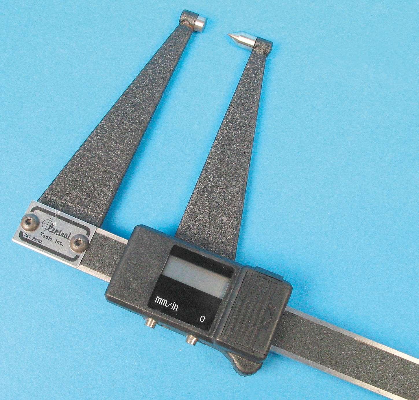
While a traditional micrometer (with f at anvils) is certainly adequate, for best results when measuring brake rotor thickness, a dedicated rotor thickness mic features both f at and pointed anvils.
After all, the hydraulic system is sealed — it is a closed circuit. The only time it is even open to the atmosphere is when the cap on the master cylinder reservoir is removed to add f uid. And you really should not have to add f uid unless there is a leak.
Since brake f uid is hygroscopic, water can also be drawn through the microscopic pores of rubber hoses and even the reservoir vent. Although there are corrosion inhibitors in the f uid, they wear out over time — up to 90% in as little as three years. The more depleted they are, the less moisture it takes to cause corrosion damage.
How often should your customers change their brake f uid? Some carmakers, particularly European manufacturers, specify f uid changes in their vehicles’ owner’s manual— usually annual inspections with f ushes every two years. Fluid change frequency also depends on geographic location. Humid conditions are worse than arid ones. For the typical car owner, you may suggest changing it every two to three years.
But for safety’s sake, offer to check the f uid at least annually. Experts claim that systems absorb as much as 3% water by volume in just 18 months.
Fresh DOT 3 f uid is required to have a
Dial indicators may be mounted using either an adjustable rod and magnetic base style mount or a f exible locking “gooseneck” mount that allows mounting with locking pliers. The only downside to the f exible style is a matter of wear and damage to the locking feature of the neck. Like any precision measuring tool, care and safe storage is vital.


boiling point of at least 401 degrees Fahrenheit. That level of 3% water can lower the f uid’s boiling point to 293 degrees F. So it’s easy to see that f uid older than 24 months can represent trouble waiting to happen.
Using paper test strips to test for water content, which was tried at one time, does little to indicate the f uid’s condition. A refractometer provides an accurate measure and an electronic refractometer, although not cheap, makes testing easy. Another trick is to use your DMM. Connect its negative lead to the negative battery post and probe the f uid in the master cylinder reservoir. Any reading over 0.30 volts indicates excessive water present.
As the amine corrosion inhibiters in brake f uid break down, copper migrates out of the brake lines. It is a rare sight, but green stuff in the reservoir is a sign of copper. Copper is like the canary in a coal mine — an early warning of trouble. Testing for free copper ions is easy with test strips designed for brake systems. The various shade of
On-car brake lathes allow you to re-machine a rotor in place. This corrects any lateral runout while eliminating variables such as rotor runout and the potential runout at the hub (eliminating any potential stack-up tolerances by including the total rotating assembly).


Always refer to the rotor manufacturerÕs minimum disc thickness before attempting to re-surface to avoid wasting time. purple represent the concentrations of copper. They also provide a good show-andtell demo when marketing a f uid f ush to your customers.
The corrosion protection can decrease even without the presence of water, especially if the vehicle is driven hard, is used to pull a trailer or is driven in mountainous terrain.
When the corrosion protection gets low the f uid should be changed and fresh f uid meeting US Department of Transportation (DOT) standards must be used. Most vehicle manufacturers call for DOT 3 brake f uid which has a minimum dry (no moisture) boiling point of 401 degrees F. DOT 4 f uids have a boiling point of 446 degrees. But always use the type of f uid specif ed for the vehicle.
Some European vehicles use mineral oil f uids. The advantage is that mineral oils do not attract water. But do not attempt to use them in vehicles designed for glycolbased f uids or the rubber parts of the brake system will be damaged. Mineral oil brake f uid is dyed green.
Silicone f uids were tried for a while, but any moisture that gets into the system is not absorbed by the f uid as it is in glycolbased brake f uids. Hence, the water tends to form vapor bubbles as it heats up to a relatively low 212 degrees F, or the water can freeze and cause an ice plug.
The distinct advantage of silicone f uid is that it will not damage paint like glycol f uids (this is why many collector-car owners may prefer silicone f uid, and was one reason Harley-Davidson used it, but even Harley has switched to glycol). Also, silicone brake f uid should never be used in a system that features ABS, since quick pressure modulation can cause the f uid to aerate/foam, resulting in temporary reduction of brake system pressure.
Why is the f uid’s boiling point important?
As you know, energy can neither be created nor destroyed. It can only be transferred. When you apply the car’s brakes, the kinetic energy of the car in motion is changed into heat energy by the pads and shoes against the rotors and drums. The heat then dissipates into the surrounding air. But under hard or prolonged braking, excess heat

is also absorbed into the f uid. When that happens, any water in the f uid may boil causing the brakes to fade or even fail.
Rotor issues
It is not uncommon to f nd metal-to-metal contact between the brake pads and rotors, particularly in states without a periodic motor vehicle inspection program. Most motorists have no idea what that noise is and ignore it in hopes that it will go away. As you know, it never does.
Another source of rotor damage is uneven lug nut torque. It happens too often and too easily. Even when the owner changes a tire, he can tighten the fasteners unevenly or excessively. Some shops don’t even use a torque wrench or torque sticks when working on wheels, which is diff cult to believe in this enlightened age. Yes, we have heard the argument that torque sticks do not have the calibration of a torque wrench, but more important is being off a few foot-pounds unevenly and warping the rotor.
In their never ending quest to reduce weight (and improve fuel eff ciency), carmakers have whittled away at weight and that includes brake rotors. The former beefy rotor has been replaced with something looking more like a slice of deli ham. Most carmakers now discourage ref nishing the rotors with each and every brake job. If you f nd no damage, leave them alone. But if the rotors are dished, suffer thickness variations

Although it’s often tough to convince some auto service shops, the use of a calibrated torque wrench is the only proper way to tighten wheel fasteners. Granted, it’s more time consuming, but this eliminates the risk of uneven tightening, which could induce warpage into the rotor. Always tighten any wheel fastener group in a criss-cross manner to evenly spread the clamping load.
Courtesy NUCAP An option to consider when trying to correct lateral alignment issues involves the use of tapered shims. These shims are available for corrections of 0.003-inch and 0.006-inch.
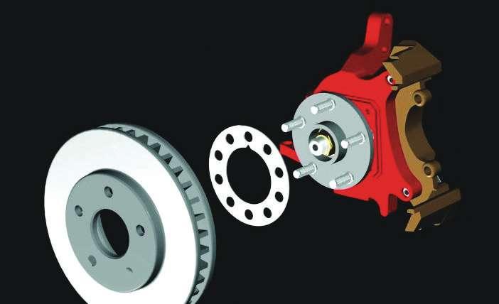
Courtesy NUCAP

This overhead view provides an example of lateral alignment correction, utilizing an alignment shim. (Illustration courtesy NUCAP.)
or have lateral runout, you must restore them to perfection (or replace them).
A dished (tapered) rotor usually causes a spongy pedal, especially following lining replacement. The old linings may have actually conformed to the dished condition. Using a micrometer, measure the rotor thickness at several points from the center out to the edge and at several spots around the clock.
Thickness variation is commonly caused by hot spots in the rotor, resulting in pedal pulsations. Instead of the contact faces being f at, they resemble a lumpy bagel. Again, use a micrometer to check that the rotor has even thickness along the entire path of pad contact.
Lateral runout is the number one cause of brake pedal pulsation. And pulsation is the number one complaint from the car owner. Noise is number two and we will get to that later. Use a dial indicator to inspect for lateral runout.
An on-car lathe can salvage many

out-of-spec rotors, but far too often so much metal gets removed that the rotor reaches the discard limit. Then, about the only option is to install replacement rotors. Yes, we said rotors as in plural. Don’t risk a comeback by replacing just one. After all, the price of most replacement rotors will not send your customers in search of a second mortgage. If, however, the rotor still has enough meat, but runout is excessive, another option is to install a shim between the rotor and hub. This may be an option for a new rotor that is otherwise in good shape.
Noise issues
As stated earlier, noise is the second biggest complaint from car owners. Noise or brake squeal may emanate from vibrations between the pads and rotors, the pads and calipers or the calipers and the mounts. Worn brake hardware is often the cause of vibrations, so replace the bolts, slides, bushings clips, shims, insulators and/or springs with each brake job. Remember to lube all moving parts with the proper hightemperature grease. And you may want to use a bit of chemical anti-noise compound on the back of the pads for good measure.
Improperly machined rotors are another source of problems. Be sure to give them a non-directional f nal f nish after turning them with a lathe. Make sure to clean any grease from the brakes before installing the wheels (following a wash with solvent, it’s a good idea to also wash and scrub the rotor with hot soapy water. This helps to remove any residual contaminants). Burnishing basics
Everybody has had at least one customer return complaining that their vehicle does not seem to brake as well as before. They are often right, especially if the rotors have been machined or replaced. Over time, some of the brake material has been transferred from the linings to the rotors. This is a good thing and improves brake feel. After a brake job, however, it may take quite some time for this transfer to happen. Meanwhile, the customer is unhappy. Unhappy, that is, unless you have f nished your job and put the icing on the cake. Your job is not done until you burnish the brakes. How?
Make about 20 stops, or near stops, from around 35 mph to 40 mph, allowing a minute or two between stops to allow the brakes to cool. Do not use heavy pressure, but brake as you normally would. Proper burnishing also reduces potential noise issues. Granted, most of us don’t have that kind of time, but even 10 deceleration cycles will cut down on complaints, so f nish the job properly.
Caliper concerns
On relatively new vehicles, you may simply squeeze the caliper piston(s) back into the bore before replacing the pads. If you chose to do that, open the bleeders so that any crud f oating around in the calipers is expelled instead of pushed back into the brake hoses. But if the vehicle has been in service for a few years or this is not the f rst brake job, you may have to rebuild the

A copper-test kit is an easy way to check for copper content in the brake f uid (which indicates degrading performance of the f uid).

For those who wish to perform further brake system diagnostics, a portable pyrometer (infrared temperature gun) allows you to easily monitor wheel, caliper and rotor temperatures immediately following a road test. Higher than average brake temperatures can pinpoint a potentially dragging caliper.
calipers. It is not a diff cult job, but it does take a little extra time at the workbench that may well be worth it to avoid a comeback. Of course, if you discover corroded pistons or damaged bores or seal channels, don’t mess around. Simply replace with new or quality reman calipers.
Only Superman can inspect the condition of the seals and pistons inside the rotors. That is why many techs now prefer to install loaded calipers — calipers with pads — that usually come complete with new hardware. It doesn’t take much longer to swap out the calipers than to swap out the pads. Besides, this provides an opportunity to f ush and f ll the hydraulic system with fresh brake f uid.
Friction technology
Brake friction material has come a long way since asbestos was banned by the Environmental Protection Agency (EPA) in the late 1980s. Yet, due to legal challenges, some asbestos has been legal in automotive friction material.
If you aren’t sure what kind of lining the vehicle you’re working on has, use all the precautions that you normally would for asbestos dust. Never ever blow the dust from a brake assembly using compressed air.
Not only is asbestos being banned, some metallic elements blended into friction compounds are being banned. In a general overview of the regulations, Peter Murnen, global marketing director, undercar and visibility products, Federal-Mogul Corp., stated: “In Washington state, brake manufacturers are required by 2013 to provide detailed information concerning the levels of materials like copper, nickel and zinc in each of their friction formulations. The state will use this information to establish baseline levels for future friction materials.
“Manufacturers selling brake products in both Washington state and California will also work with an outside testing agency, NSF International, beginning Jan. 1, 2013.
“The next major milestone... will be Jan. 1, 2014, when friction materials may not exceed established levels of certain compounds, such as lead, asbestos f bers... as well as chromium
A DVM can be used as a quick check of the brake f uid’s condition. Anything over about 0.30V indicates degraded f uid that should be f ushed out and renewed. (Photo by author.) six and cadmium. Then, beginning in 2021 manufacturers cannot sell friction materials that have greater than 5% of copper by weight. In 2024, the copper content must drop to less than 0.5% by weight. The elimination of copper is signif cant because most ceramic friction formulations use copper as an abrasive element.”
Regulations on copper content are intended to reduce the amount of the material that’s entering waterways and water tables.
Wagner, a Federal-Mogul brand, reportedly has already begun to transition some of the latest low-copper formulations into its aftermarket line of ThermoQuiet CeramicNXT pads.
Also on the technical front, ACDelco has introduced a surface coating to its brake pads that helps reduce the break-in period and improves pre-burnish brake effectiveness for police cars, according to the company. The coating is designed for the police duty cycle, including high-speed driving. The new coated pads provide coverage for Chevrolet Caprice, Impala and Tahoe; Ford Crown Victoria and Interceptor; and Dodge Charger police vehicles.
During pad break-in or “burnishing,” the ACDelco coating that was applied to the friction surface during manufacturing transfers quickly to the rotors. The coating may temporarily release visible airborne gasses as it transfers material onto the brake rotor during the burnish procedure, according to the company.
The new pads would be available only to professional installers who service f eet vehicles. ●