16 minute read
Getting up-to-speed

by EndeavorBusinessMedia-VehicleRepairGroup

Advances in ride control
Getting up-to-speed on electronic suspension control
By Mike Mavrigian
Once upon a time, ride control simply referred to providing a vehicle with a comfortable driving experience while limiting excess body roll. This was primarily addressed by the automakers by the selection of the appropriate springs, shock absorbers that would dampen spring movement and anti-roll bars that somewhat tamed, or limited, excess body lean during turns or steering maneuvers.
A properly controlled suspension system, or “ride control” system, is enlisted with the responsibilities of controlling spring and suspension movement, enhancing tire life, providing consistent and predictable handling and braking, maintaining wheel alignment, and minimizing excessive body lean and body dive.
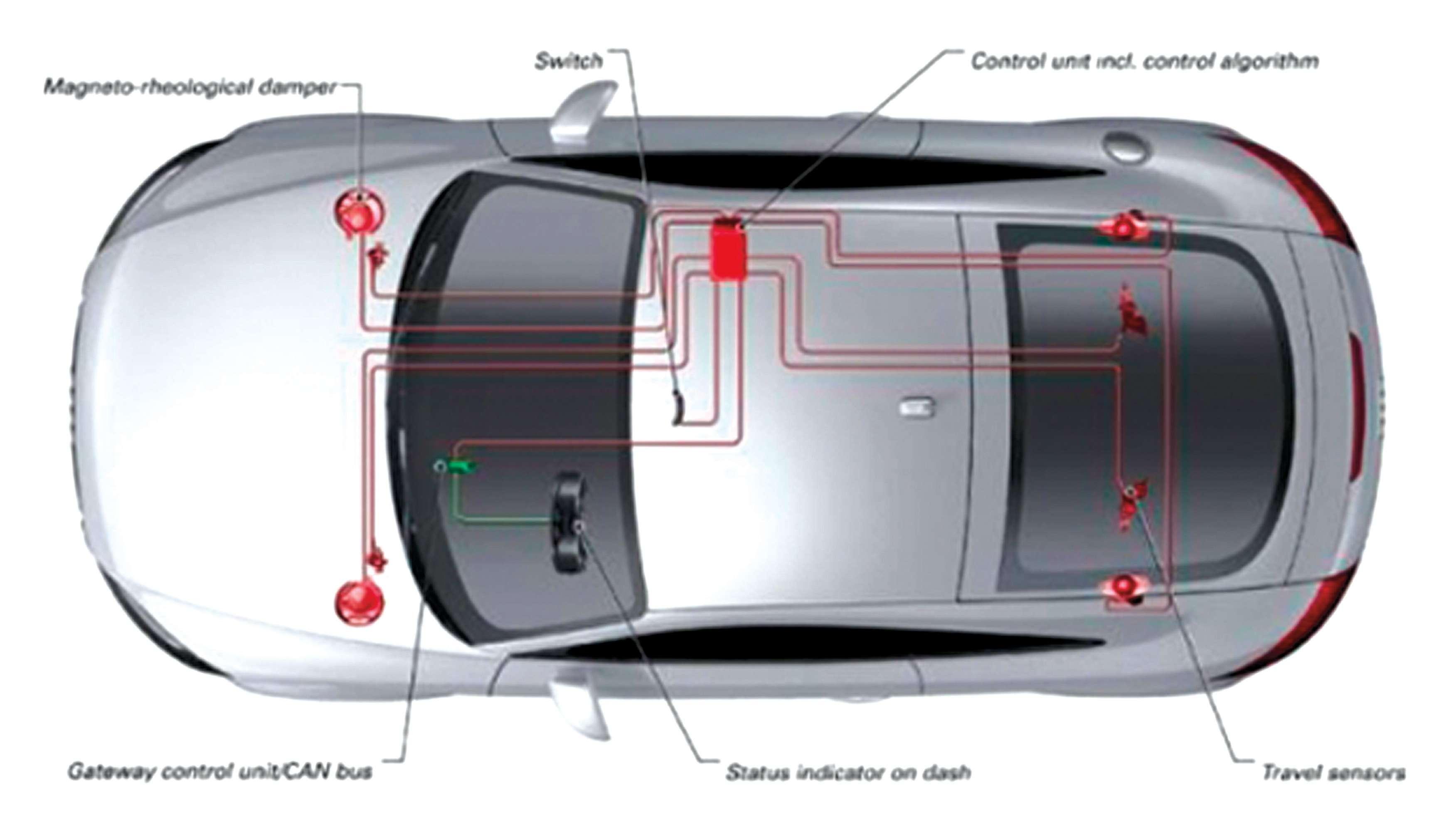
Magneto-rheological damperagneto-rheological damper Switch
It should come as no surprise that with today’s ever-advancing and ever-encroaching computer control and management systems, the once mechanically operated suspension systems have now entered the management-by-ECU realm.
Generically, suspension systems that are “controlled” or “managed” by means of electronic aid may be referred to as “adaptive” or “active” suspensions.
Examples of vehicles that feature some sort of adaptive suspension system include such models as the 2008 Lexus GS350 with its adaptive ride control (this uses small electric motors attached to the upper tips of the shock rods to rotate the rods, changing damping characteristics much in the way that was once handled by manual adjustment on some adjustable performance shocks), 2002 and later Cadillac STS, GMC
Control unit with control algorithmontrol unit with control algorithm
Gateway control unit/CAN busateway control unit/CAN bus Status indicator on dashtatus indicator on dash
Travel sensorsravel sensors

Magneto-rheological fuidagneto-rheological f uid in non-magnetic staten non-magnetic state Rebound directionebound direction
Electromagneticlectromagnetic coil

High pressureigh pressure
Magneto-rheological fuidagneto-rheological f uid in magnetic staten magnetic state
Line of magnetic feldine of magnetic f eld
Magnetic feldagnetic f eld MR mediumR medium MR effectR effect
Low pressureow pressure
An example of a magneto-rheological piston. At the top left, an example of the MR f uid in a non-magnetized state. Below left is an example of the MR f uid when a magnetic f eld is applied.
Yukon and Corvette with GM’s MagneRide system that uses a magnetic f uid approach, 2003 Volkswagen Phaeton’s continuous damping control, 2003 and later Mercedes Benz Airmatic, 2004-2007 Volvo 4-C active chassis system, Audi’s magnetic ride, just to name a few.
Basically, everyone’s getting into the act in terms of offering advanced ride control systems that may still be mechanically operated, but electronically controlled.
As this trend continues, shops, both dealer and independent, will begin to see more vehicles that are equipped with these systems.
Here, we’ll provide an overview of select systems in order to offer a bit of insight into their workings. Magnetic ride control
Magnetic ride control, also known as “magneto rheological” technology, involves shock absorber units that feature electromagnetic oils within the shock’s piston, and are f lled with a very sophisticated magnetic particle-infused polymer liquid. An electrical charge is delivered to the liquid (timed and controlled by an ECU that receives input data from a series of sensors), causing the magnetic particles within the f uid to change their shape, or density, which quickly changes the liquid’s viscosity (thinner when the system wants freer movement, thicker when damping needs to be more f rm). The special “magnetic f uid” can change from a relatively thin viscosity to an almost plastic state faster than you can f ick your f nger. This altering of the state of viscosity changes (or is capable of changing) at an astonishing rate of up to 1,000 times per second as commanded by the system’s ECU. Electro-hydraulic control
Rather than pouring through every system out there, let’s take a look at the CES (Continuously Controlled Electronic Suspension) system developed by Tenneco for the OEM market. This is a semi-active system that is triggered by a dedicated ECU
that receives and interprets data from a range of sensors including front and rear mounted acceleration sensors that detect body up/down movement, a steering angle sensor, vehicle speed sensor, brake pressure sensor and sensors that detect lateral body movement
Summary view
Considering the advanced (and everevolving) electronic-hydraulic and magnetic suspension control system technology, the capabilities of these systems may very well do away with the need for anti-sway bars, as these systems become more capable of controlling lateral body movement in relation to the suspension.
As these systems become more incorporated into mainstream vehicles, the aftermarket is beginning to respond with direct replacement shock absorber units. The trend of OE control systems will continue to proliferate beyond applications for high-end luxury and performance vehicles.
Vehicle-specif c example: Lexus AVS
A specif c example of an adaptive variable suspension (AVS) is the 2008 Lexus GS350. This system approach features control actuators that are mounted to the top of the struts/shocks. By monitoring the various vehicle sensors, the absorber ECU controls the actuators, varying the damping control of the hydraulic shocks/struts.
Monitoring and actuating components for the system include front and rear acceleration sensors, yaw rate sensor, steering angle sensor, skid control ECU, and the ECM (which sends a drive torque signal to the absorber control ECU).
The AVS, as a system, includes each shock’s absorber control actuator, a front acceleration sensor which detects vertical acceleration of the left front of the vehicle, a rear acceleration sensor, a yaw rate sensor that monitors lateral (side to side) and longitudinal movement, a steering angle sensor, and a dedicated shock absorber ECU. By the way, the absorber control ECU houses the right-front acceleration sensor. The skid control ECU and the front steering
Magneto-rheological fuid inagneto-rheological f uid in an unmagnetic staten unmagnetic state

M a g n e t i c f e l d l i n e s Magnetic f eld lines M a g n e t i c Magnetic f e l d l i n e s f eld lines
Magneto-rheological fuid inagneto-rheological f uid in a magnetic feld magnetic f eld
Another view of a magneto rheological piston. The MR oil f ows through channels in the piston, with the f uid f ow restricted when the magnetic f eld is energized. control ECU send data that is incorporated into the ECM’s decision-making process to control damping.
Where are these system sensors located? The front LH acceleration sensor is located under the left side of the dash, requiring removal of the instrument panel undercover, the instrument side panel, the LH door scuff plate and front door opening trim cover, behind the carpet.
NOTE: In order to inspect the front LH acceleration sensor, connect three 1.5-volt dry batteries in series. Connect terminal 3 (SGB) to battery positive and terminal 2 (SGG) to battery negative (do not test this with the vehicle’s 12V system — you must use three 1.5V batteries connected in series). With the batteries connected to the sensor terminals, connect a voltmeter between terminals 1 (SGFL) and 2 (SGG). With the sensor stationary on a workbench, voltage should read approximately 2.3V. Next, hold the sensor in a vertical position and vibrate it. The voltage reading should change between about 0.9 and 3.6V.
NOTE: If the sensor is tilted, a different voltage value may be output. Don’t apply more than 6V to the sensor, and don’t drop it. If dropped, chances are the sensor will be damaged and must be replaced. Also, never place the sensor upside down at any time.
The rear acceleration sensor is located in the right side of the trunk, just ahead of the right hinge, behind the trim cover. As with the front sensor, it’s advised not to place the sensor upside-down, and avoid dropping it.
The procedure for testing the rear acceleration sensor is similar to testing the left front sensor. With the sensor removed and laying on a workbench, connect three 1.5V batteries in series, with the positive connected to the sensor’s terminal 3 (SGV) and negative to terminal 2 (SGND). Connect the voltmeter to terminals 1 (SGRR) and 2


(SGND). With the sensor stationary, voltage should read approximately 2.3V. While holding the sensor in its normal vertical position and while vibrating the sensor, the reading should change between about 0.9 and 3.6V.
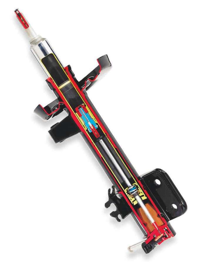
Cutaway view of a typical magneto rheological damper.
The absorber control ECU (which includes the right front acceleration sensor) is located under the right side of the dash, mounted vertically. Here’s a tip: Don’t simply begin to remove this ECU. After turning the ignition switch off, disconnect the vehicle battery negative cable, and then wait at least 90 seconds in order to disable the airbag (SRS) system. By the way, if this ECU is being replaced, you’ll need to perform a registration of vehicle identif cation information.
Vehicle identif cation information is automatically acquired when the system enters its test mode.
The yaw rate and acceleration sensor is located in its traditional location, under the center console box.
The shock absorber actuators are mounted atop each shock’s rod, under the upper shock absorber cap. The actuator engages to the top of the shock’s rod, keyed to an internal damping adjustment driver. This is similar to an aftermarket shock that’s manually adjustable. In this case, electronic actuators turn the adjusters, commanded by the ECU as a result of information provided by the system’s vertical, lateral and longitudinal sensors.
Use a jumper wire to connect terminals 12 (TS) and 4 (CG) of the DLC3 diagnostic port. Turn the ignition switch to the on position. The “SPORT S+” indicator in the information display should blink in the Test Mode blinking pattern, blinking once every 0.125 seconds. If the display does not blink, there’s a problem with the indicator light.
Check the absorber control actuator operation. Starting with the SOFT position, depress the brake pedal. Using the appropriate scan tool, determine if the absorber actuator position increases by two steps, every time the brake pedal is depressed. You
Accelerationcceleration sensor ECU
Steering sensorteering sensor
CES sensorES sensor
CES sensorES sensor

Output Input
Displacement sensorisplacement sensor Acceleration sensorcceleration sensor
Tenneco’s CES (continuously controlled Electronic Suspension). Note the front and rear acceleration sensors, steering sensor, CES dampers and displacement sensor.

should see the actuator position move from SOFT to 3, to 5, to 7, to 9, to 11, to 15, to 17 (the HARD position). Bounce the vehicle and conf rm that the shock absorber(s) is getting stiffer on compression.
Every time the brake pedal is depressed, the absorber control actuator rotates in 15-degree increments to a maximum angle of 120 degrees. If the actuator does not rotate, suspect the actuator circuit.
Once the inspection is complete, turn the ignition switch to the off position, and then disconnect the jumper wire from the DLC3. Then you can turn the ignition switch to the on position. If the ignition switch remains on after the jumper wire has been removed, the vehicle will remain in the Test Mode.
In order to remove the shock absorber control actuator, remove the shock cap and disconnect the actuator wire connector. Turn the actuator counterclockwise 40 degrees.
In order to inspect the control actuator, use a multimeter to measure the actuator resistance. Citing the front actuators as an example, note that connections on the right front differ from that of the left front actuator.
In order to install the actuators, engage the actuator to the shock rod and turn the actuator clockwise 40 degrees. ●
Computer-controlled adaptive suspension glossary
Absorber control actuator Small actuator motor connected to the top of the shock piston rod in an adaptive system where a signal from the ECU adjusts shock damping. An example of this is found in the 2008 Lexus G350.
Absorber control ECU Dedicated ECU for an adaptive suspension system.
AVS Lexus term for their Adaptive Vehicle Suspension system.
CES Tenneco’s Continuously Controlled Electronic Suspension system developed for a variety of OEM applications.
CDC Continuous damping control. This is the term used for many of Ford Motor Corp.’s European applications.
4-C active chassis Volvo’s terms for the active suspension featured in the S60R and V70R models.
FlexRide TThe trm used by Opel for their active suspension.
Acceleration sensor Detects the vertical acceleration of the body.
Front steering control ECU This ECU sends the VGRS (variable gear ratio steering) operation angle signal to the absorber control ECU.
MagneRide GM’s name for their magneto-rheological systems. Magneto rheolocical A magneto-rheological f uid (generally called MR fluid) is a highly specialized type of f uid containing dense magnetic particles that quickly changes viscosity when subjected to a magnetic f eld. This f uid can change from free-flowing to an almost solid plastic state by varying the strength of the magnetic f eld. When used to control shock absorber damping, it reacts very quickly, as fast as 1,000 times per second.
Rear acceleration sensor Detects the vertical acceleration of the rear of the body.
Skid control ECU (brake actuator assembly) This ECU sends the vehicle speed signal to the absorber control ECU as part of the data used to determine suspension damping. It also sends the brake pedal depressed signal to the absorber ECU. It sends a request for damping force control to the absorber ECU.
Steering sensor Detects the steering direction and the angle of the steering wheel. Another aspect of input information used by the adaptive suspension system to control shock damping.
Yaw rate sensor Detects the vehicle’s longitudinal and lateral acceleration and deceleration. This is another integral bit of data fed to the adaptive suspension system in terms of detecting body movement.

How electronic stability control can improve ride control sales
By Ann Neal stopping distances. Replacing worn shocks
Electronic stability control (ESC) is systems continue to work as intended.” nothing new. Introduced as optional ESC depends on the tires’ ability to grip equipment on luxury cars in the the road. “All of these crash avoidance sysmid-1990s, it’s been standard on light-duty tems’ effectiveness is largely attributed to truck and passenger vehicles since 2012. ride control components,” says McGovern.
What is new is the prof t potential built A crash-avoidance system’s instructions to around helping motorists understand how change the vehicle’s behavior, such as brakESC works and depends on ride control ing individual wheels, occur whether or not components to function effectively. the vehicle is capable of executing them.
You need to be aware of the relationships of the supporting mechanical systems that allow the crash avoidance technology to function, according to Mac McGovern, director of marketing and training, KYB Americas Corp. For example, tires slow and turn a vehicle, not ESC. As suspension, springs, shocks and struts wear, their ability to control the tires lessens.
“ESC and other crash avoidance
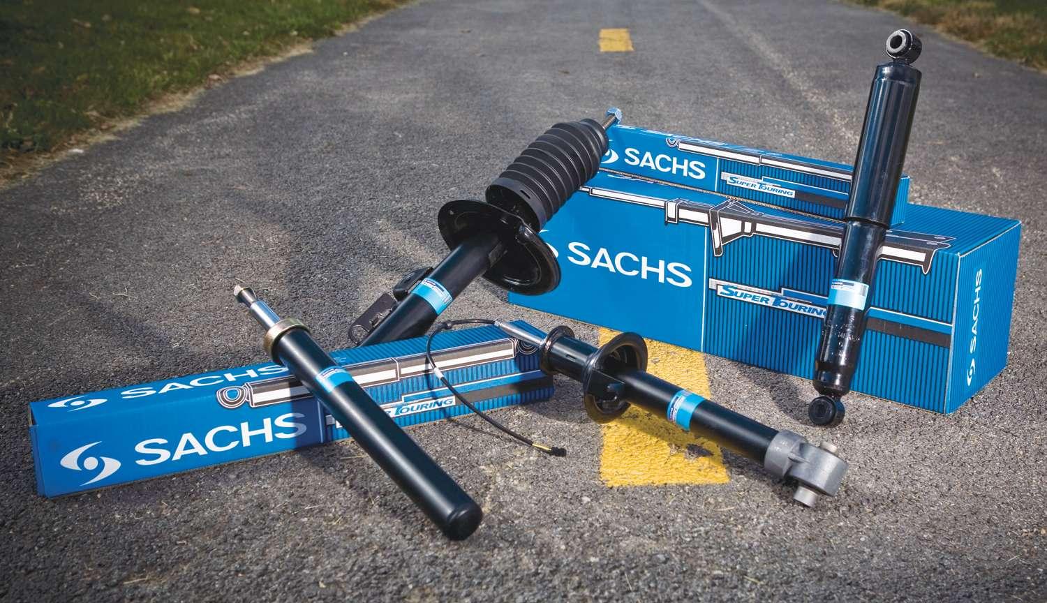
ZF Services says the Sachs brand original replacement systems will work properly, but shocks and struts are engineered to restore original may have to work too hard or dynamics while meeting the highest safety standards. too often or may not be effective and struts will ensure the vehicle’s safety if there are worn or miscalculated parts in “If the technology is expecting the vehicle the steering, suspension, brakes or tires,” behavior’s to stay within vehicle design says McGovern. And this gives you the so it can contribute to consumer safety, it opportunity to show customers their worn only makes sense that the service provider parts and explain what it is doing to their understand that technology and make recvehicle. ommendations around this safety system so
Vehicle safety systems such as antilock the customer has a better sense of the value brakes and ESC depend on input from the proposition.” wheels to work properly, according to Eric ESC is a technology that you certainly Banas, product marketing manager for ZF should be aware of but not afraid of, Services LLC, manufacturer of Sachs shocks according to Bill Dennie, director, ride and struts. “As shocks and struts wear, control channel management for Tenneco the damping characteristics are reduced, Inc., the manufacturer of Monroe shock increasing the chances of excessive wheel absorbers and struts. “If you are relying hop over bumps or hydroplaning in wet on a quality brand of shocks and struts, conditions, which can lead to extended you can be conf dent that there will be
no compatibility issues whatsoever with a vehicle’s ESC system, just as you should not worry about which brand of brake pads you are installing on a vehicle equipped with antilock brakes.”
Properly functioning shocks and struts not only smooth out the bumps in the road, they help the vehicle’s safety systems do their job when needed, says Banas.
As consumers bring ESC-equipped vehicles to shops for servicing, what do you need to do to ensure the crash-avoidance technology functions properly? “A shop can’t assure that ESC will operate properly, they can only look for electronic trouble codes, look for wear or failure of any ride control component and road test the vehicle. The shop’s role is to keep the motorist informed about conditions that could prevent ESC from being as effective as possible when a sudden need occurs,” says McGovern.
McGovern suggests helping the motorist understand that electronic safety systems depend on ride control components that wear and that replacement parts should always meet or exceed OEM performance capabilities. “Crash avoidance can’t avoid and stability control can’t control if the tires can’t grip the road or the body control isn’t stable. KYB’s focus is on products that restore designed performance because it’s critical to the vehicle’s safety systems.”
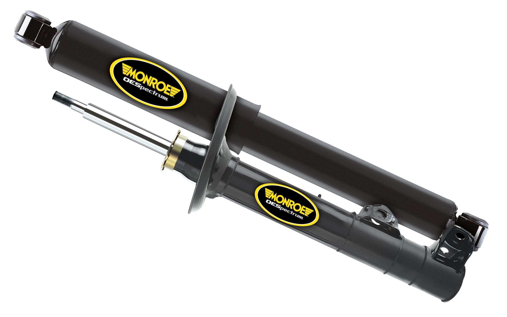
The OESpectrum line represents Monroe’s latest ride control technology. It is engineered to ensure OE-quality performance of the electronic stability control system.
Because ESC and crash avoidance systems are electronically looking at the steering, suspension, brake and tire systems at once, a shop can put together a sales plan that complements vehicle technology, according to McGovern. “The relationship between mechanical and electronic is critical to overall vehicle performance so that’s the beginning of the value proposition. The customer understands tires and the customer understands safety systems, so let’s build a selling culture around that.”
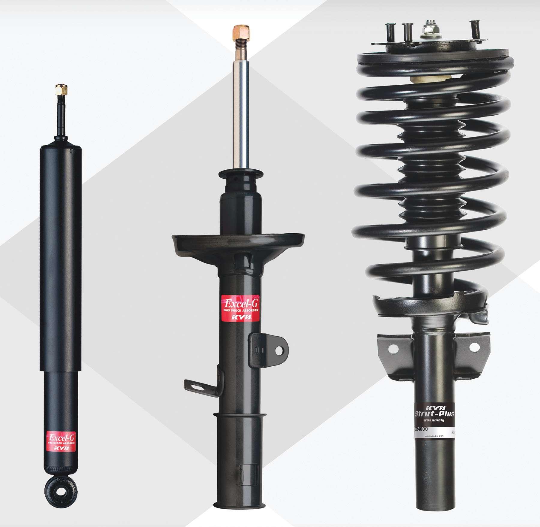
KYB Americas Corp. says its shocks and struts are engineered to work properly with ESC-equipped vehicles.
McGovern says earning a sale is a process and suggests looking at sales of ride control components from the customer’s perspective.
“They don’t like surprises and they can’t make high-dollar decisions on the spot. So earning shock and strut sales is about planting the appropriate seeds. Do that by reporting on current vehicle conditions. Do that by setting goals or expectations of the vehicle which usually needs to be designed vehicle performance.
“You help them understand what it takes to keep their vehicle within those performance capabilities. Then you offer shocks and struts and the opportunity to think about it.”
Closure on a sale usually happens on the f rst follow-up visit, according to McGovern. “So the advice to the store is not to create a selling plan; it is to create a planting seeds plan because you have to concentrate on the f rst follow-up visit.” ●


