
11 minute read
How do you know if that heater fault code is real?

from Auto Service Professional - February 2016
by EndeavorBusinessMedia-VehicleRepairGroup

Oxygen sensor heaters
How do you know if that heater fault code is real?
By Jacques Gordon
Jacques Gordon has worked in the automotive industry for 40-plus years as a service technician, lab technician, trainer and technical writer. His began his writing career writing service manuals at Chilton Book Co. He currently holds ASE Master Technician and L1 certifcations and has participated in ASE test writing workshops.
When the check engine light is on and the scan tool displays oxygen sensor codes, you already suspect that the real problem might be something other than the oxygen sensor. When the codes indicate a problem with the oxygen sensor heater, that narrows the possibilities quite a bit. However, if it’s Sensor 1, even if you determine the circuits and power supply are good, simply installing a new sensor isn’t a complete fx because the powertrain control module (PCM) won’t automatically work with the new sensor heater. They must be introduced to each other frst.
The air/fuel ratio sensor (AFR), also called a wide-band oxygen sensor, was frst introduced about 15 years ago, and since about 2005 it’s Sensor 1 in just about every engine. An oxygen sensor only indicates whether the engine is running rich or lean of stoichiometric (lambda = 1), while the AFR sensor actually measures the amount of oxygen in the exhaust. This allows the PCM to precisely control the engine’s air/ fuel ratio rather than just correct for a rich or lean mixture. The AFR sensor is a very sophisticated measuring device that must be kept at a constant temperature to measure accurately, so the heater is critical to its operation.
To understand the heater in an AFR sensor, it will help to review how an oxygen sensor works. There are three types of oxygen sensors: the passive Nernst cell, the powered titania sensor and the AFR or wide-band oxygen sensor.
The basic oxygen sensor is based on the Nernst cell, named for the German physicist who developed the equations that defne how it works. In physical chemistry, a Nernst cell is a semi-permeable wall made of a material that conducts ions. Electrical contacts are attached to each side of the wall. When there are different concentrations of the same gas on either side of the wall, a voltage is generated.
In a standard O2 sensor, the cell wall is a thin wafer of zirconia that reacts to different concentrations of oxygen in an engine’s hot exhaust stream (660 degrees Fahrenheit or 350 degrees Celsius). When there is a high concentration of oxygen on one side of the wafer and a low concentration on the other, the oxygen on the “high” side will cause ions to fow through the wafer to the “low-oxygen” side. The fow of ions creates a voltage that’s picked up by the electrodes attached to each side of the wafer. This type of sensor can generate about 1 volt, and it’s completely passive.
The sensor’s zirconia wafer is shaped like a thimble, and the outside wall is exposed to exhaust gas while the inside wall is exposed to ambient air. One electrode is attached to the sensor body so it’s grounded at the exhaust pipe. That means that only one wire is needed to send the voltage signal to the PCM. A hollow sheath around that wire provides outside reference air to the inside of the thimble.
In comparison to thimble and planar types, the wide-band sensor (bottom) produces a current signal that the PCM converts to a voltage signal for diagnostics.
A titania sensor is very different. When heated, the electrical resistance of titania changes as the concentration of oxygen surrounding it changes. A titania sensor does not generate voltage... it changes the output voltage of the current fowing through it.
The sensor element is a fat wafer with electrodes on either side, so it’s sometimes called a “planar” sensor. The PCM supplies a constant reference voltage to one electrode and measures the voltage drop through the element at the other electrode. Since the reference voltage is typically 5 volts or higher, this sensor produces a nice fat signal that reacts much faster than a Nernst cell, and it doesn’t need reference air either, so it’s smaller and less vulnerable to contamination. But like the zirconia sensor, the output signal is not linear; it rises or falls sharply on either side of stoichiometry, so it’s still only capable of indicating a rich or lean air/fuel ratio.
Air/fuel ratio sensors have a Nernst cell and a second cell right next to it called an “oxygen pump” or pump cell. The two cells are built on a fat strip of zirconia, so it’s sometimes called a “planar” oxygen sensor. Be careful not to confuse it with the titania sensor.
Just like the basic O2 sensor, the Nernst (sample) cell generates a voltage when there’s very little oxygen in the exhaust. However, instead of using that voltage signal for fuel control, it’s sent to a control circuit that operates the pump cell, which is basically another Nernst cell operated
in reverse. When current is applied to the pump cell, oxygen ions fow out of it and into the sample cell. A controller supplies current to the pump cell, and it’s programmed to keep the output of the sample cell at 450 millivolts. This creates a closedloop control system, and the PCM simply monitors the amount of current supplied to the pump cell to know how much oxygen is in the exhaust.
In addition to being extremely fast, this type of sensor can actually measure the amount of oxygen in the exhaust over a very wide range rather than just detect a rich/lean condition. This allows the PCM to control air/fuel ratio over a range from 10.3-to-1 (rich) to about 23-to-1 (lean).
In earlier AFR sensors, the sheath around the wiring harness forms a sealed conduit that supplies ambient air to the pump cell. These sensors are vulnerable to contamination, especially if the sheath is damaged (that’s one reason we’re told not to repair the wiring harness).
Newer AFR sensors are confgured differently so the sheath is no longer needed. These sensors are different from each other and require different control circuits, so they’re not interchangeable.
Sensor heaters
Basic four-wire O2 sensors are still used as catalyst monitors and labeled sensor S2 on bank 1 or bank 2 (B1S2 or B2S2). The heater brings the sensor up to operating temperature quickly so it can begin working as soon as possible. The PCM monitors the heater circuits continuously, checking resistance for an open circuit or short to ground.
If a problem is detected, the PCM will set a code and turn on the malfunction indicator light (MIL), but the sensor can still produce a signal if the exhaust gas keeps it hot enough.
AFR sensors might also produce a signal without the heater, but that signal would be completely useless because it’s not voltage... it’s a measure of the current sent to the oxygen pump. Temperature affects resistance and resistance affects current fow, so the sensor’s fat zirconia strip must be held at a constant temperature to generate an accurate signal. The sensor is heated to about 1,200 degrees F (650 degrees C), double the temperature of a basic heated oxygen sensor.
Sensor heaters can draw a lot of current, so battery voltage is usually supplied directly to the heaters through a relay and a fuse. The heaters’ ground circuit is controlled by the PCM. A basic four-wire sensor heater is usually turned on all the time, but the AFR heater’s ground circuit is pulse width-modulated to keep the temperature constant regardless of exhaust gas temperature.
There is no temperature sensor in these heaters, so how does the PCM keep the AFR sensor at a constant temperature? Remember that temperature affects resistance, so the PCM can calculate the sensor’s temperature by monitoring the resistance in
Stay current on lambda, titania and AFR sensors
A regular oxygen (lambda) sensor signal rises and falls as the A/F ratio toggles between rich (high) and lean (low). A titania sensor signal also toggles rich/lean, but lean is high and rich is low. The AFR sensor signal does not toggle between rich and lean because it does not produce a voltage signal. It produces a current signal that the PCM uses to maintain a specifc air/fuel mixture.
However, when reporting oxygen sensor readings for on-board diagnostics or for a scan tool, the PCM mathematically converts that current signal to a voltage signal. At stoichiometry, the oxygen sensor PID will hover near 3.3 volts. If the PCM commands a rich mixture for acceleration, there is very little oxygen in the exhaust and the sensor PID will be less than 3.3 volts. A lean mixture will produce a PID above 3.3 volts.


the heater circuit. General Motors (GM) the sensor’s actual temperature under all calls this Resistance Calculated Oxygen conditions. Sensor Heater Temperature (RCOHT). The Even with a calibration resistor, the heatsame principal is used to measure coolant er’s resistance varies by a few hundredths temperature, but in this application the of an ohm from one AFR sensor to another. measurements must be extremely fast and That’s why the PCM and the AFR sensor infnitely more precise. heater must be calibrated to each other.
The heater circuit has a calibration resisThat’s also why there is no heater resistance tor built into the wiring harness or sensor specifcation, so measuring heater resisconnector. tance is not a good way to confrm a good/
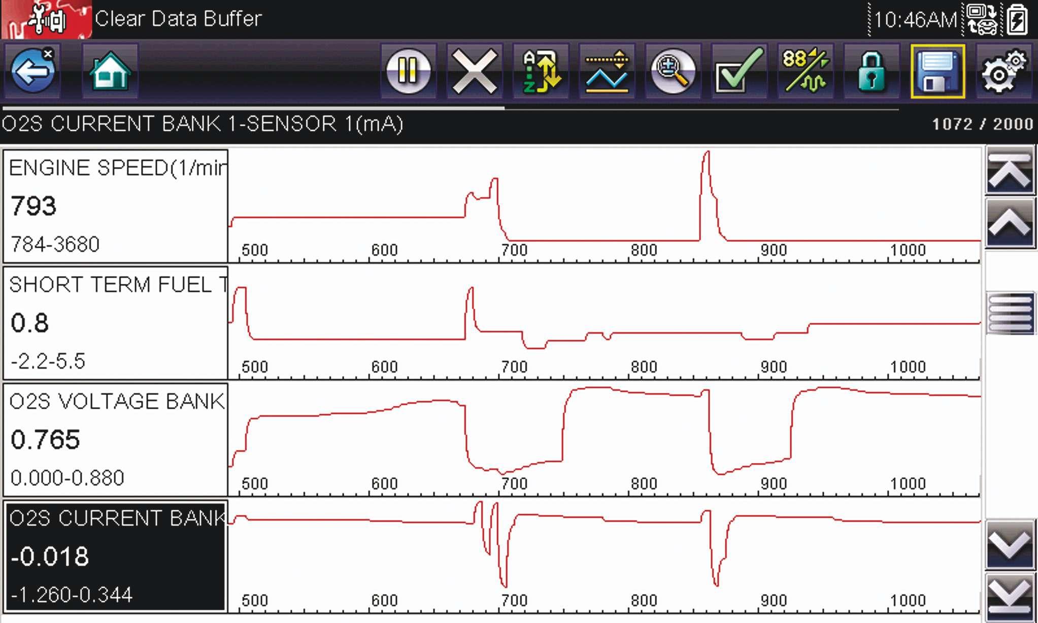
When the sensor is frst installed and bad oxygen sensor heater. In addition, connected, the PCM is commanded to read that’s the other reason we’re told not to the resistance in the (cold) heater circuit to repair an AFR sensor’s wiring harness; the know the calibration of that resistor. It will resistance might change. then use that resistance value to calculate When replacing an air/fuel ratio sensor, you’ll need a scan tool capable of commanding the PCM to relearn the sensor heater’s resistance. On some models, simply clearing the trouble codes and turning off the MIL will do the job. Some scan tools won’t enter the clear-code mode if no codes exist. In that case, just turn on the ignition and disconnect any convenient sensor to create a code. On some On this 2013 Honda Acura 2.4L engine with the scan tool reading enhanced (OEM) data, the air/fuel sensor signal is reported as models the relearn must both voltage and current. It is interesting to note that they don’t be done with the sensor cycle up and down when the rpm is steady. at ambient temperature.

On many GM models it can be done with When certain faults are detected, such the sensor hot, and the PCM will relearn the as high current draw in the heater circuit, real value at the next cold-start. the PCM will suspend heater operation to Heater monitors diagnose correctly, because if the PCM does
When chasing sensor heater codes, frst not ground the heater circuit, it can be make sure the heater monitors have run. hard to tell if the problem is in the circuit On most models it’s the frst monitor to or the PCM. run, and the other monitors might not run Here’s a test you won’t fnd in any service if that one doesn’t or if it fails. Typically manual. Unplug the sensor and connect that monitor will run during a 40 mph to a small light bulb to the heater circuit. A 50 mph cruise with the engine at normal side-marker bulb will do nicely, and make operating temperature, but the monitor sure you’re connected to the heater circuit enabling criteria are different for each manufacturer, so it’s important to look that up in the service information.
The PCM monitors the oxygen sensor heater circuits for both voltage and current. On most models, the voltage monitor runs continuously and the current monitor runs at least once per drive cycle after specifc enabling criteria are With the scan tool reading enhanced (OEM) data on a 2013 Acura, the met. Newer Chrysler tool reports heater duty cycle and sensor plus/minus signal voltage. Control current for the oxygen pump cell can fow in either direction models are a little depending on what’s required to keep AF lambda at 1.00. different; the heater protect itself. This can be a challenge to monitor runs after a complete (defned) and not the sensor circuit. Clear the codes drive cycle with the engine off and coolant and turn off the MIL, then turn on the ignitemperature has decreased more than 60 tion switch. degrees F (16 degrees C). If the bulb lights or pulses, the circuit has
The voltage monitor simply checks for power and the PCM is attempting to operate battery voltage in the heater circuit. The the heater. current monitor checks to see if current The generic OBD-II codes for oxygen in the circuit is within a specifc range. sensor heater malfunctions are useful, Depending on the model, it can range anyand the manufacturer-specifc codes are where from 0.2 amps up to about 8 amps or even more helpful. Still, the real challenge more. is telling the difference between a failed
Most manufacturers list that spec in sensor and a faulty PCM. their service information, so you can The key to that is understanding the check heater current yourself with a curcontrol strategy, diagnostic monitors and rent probe. On AFR sensors, you can also enabling criteria, so start by looking up the see heater current duty cycle with an amp description and operation and searching for probe and a DVOM or with a scope, but you TSBs in your service information system. probably won’t fnd a specifcation. Then proceed with confdence. ●


