
17 minute read
Service guidelines to aid in your diagnosis

from Auto Service Professional - February 2016
by EndeavorBusinessMedia-VehicleRepairGroup

with new or used rotors, always clean the disc surfaces thoroughly. While spray brake cleaning solvent is viable and certainly helps to remove surface contaminants, it’s best to hand-wash and scrub the discs with a mix of hot water and Dawn dish washing liquid and a bristle brush. The Dawn brand specifcally seems to work best for removing oils and particles from the machined surfaces. You can certainly follow up with brake cleaning solvent, but don’t rely on the solvent alone. Seriously, wash with Dawn and then dry. Even leading rotor manufacturers recommend the use of Dawn.
Drilled or slotted rotors
You may wonder why some rotors are drilled with a series of holes and/or feature slots that have been machined into the disc surfaces. This approach was initially developed in aircraft and most notable motorsports applications. Cross-drilled holes or slots improve brake “bite” while allowing gasses that are created between the pad
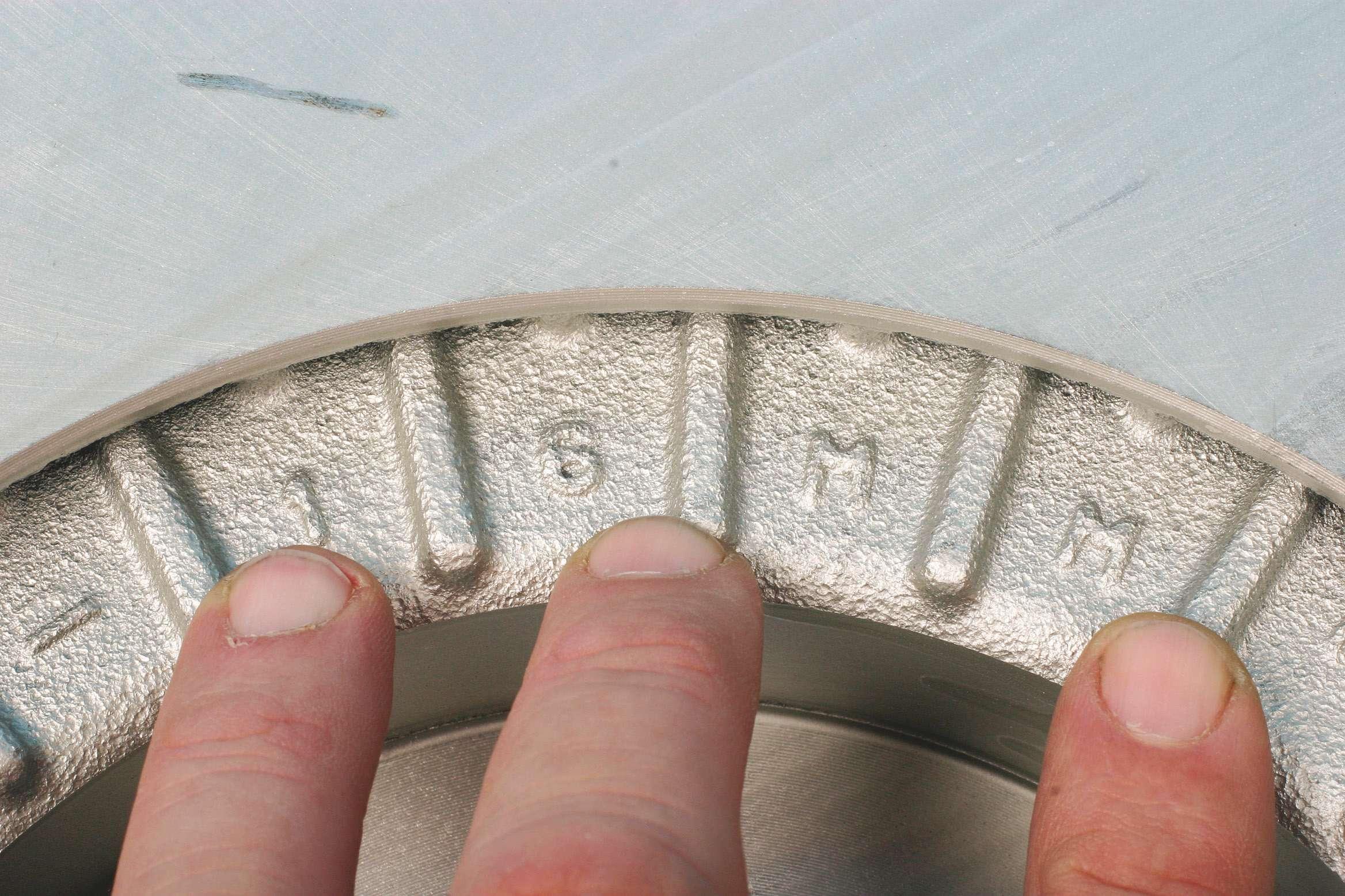
The machined grooves seen on this Dodge Charger police car aid in self-cleaning the pads. The increased surface area created by the grooves also helps to dissipate rotor heat. and disc to evacuate (think of tires with tread designs that prevent hydroplaning on a wet road).
In addition, the holes or slots help to clean
Rotor cleanliness is an absolute must when performing a new rotor and pad installation. The disc surfaces must be cleansed of all oils and particulates. Washing and scrubbing with hot water and Dawn dish washing liquid is highly recommended.

Rotors that feature cross-drilled holes and grooves are designed to reduce hydro-gassing between the pads and disc surfaces, as well as aid in pad debris removal. These features can promote superior braking by reducing gas buildup and increasing the coeffcient of friction. the surfaces, reducing pad material buildup on the machined disc surfaces. Slotted rotors (with no cross-drilled holes) offer a more aggressive pad bite and greater strength (a prime consideration for racing conditions), while holes are a bit more “pad friendly.”
A combination of holes and slots are a good compromise for superior braking and extended pad life. In case you wondered, holes and/or slots are not for appearance only. They do serve a function, providing the placement and size of the holes/slots have been properly engineered for a given application.
Never modify a rotor. If the customer wants drilled or slotted rotors, buy them as needed. Holes and/or slots are precision machined. Trying this on your own can lead to disc fractures and out-of-balance conditions.
Rotor runout
Whenever servicing used rotors, always take the time to make a few measurements, even if the customer hasn’t complained about a bouncing brake pedal. Measure lateral runout, disc thickness and measure for thickness variation.
Poorly machined or abused rotors, or rotors that have been warped as a result


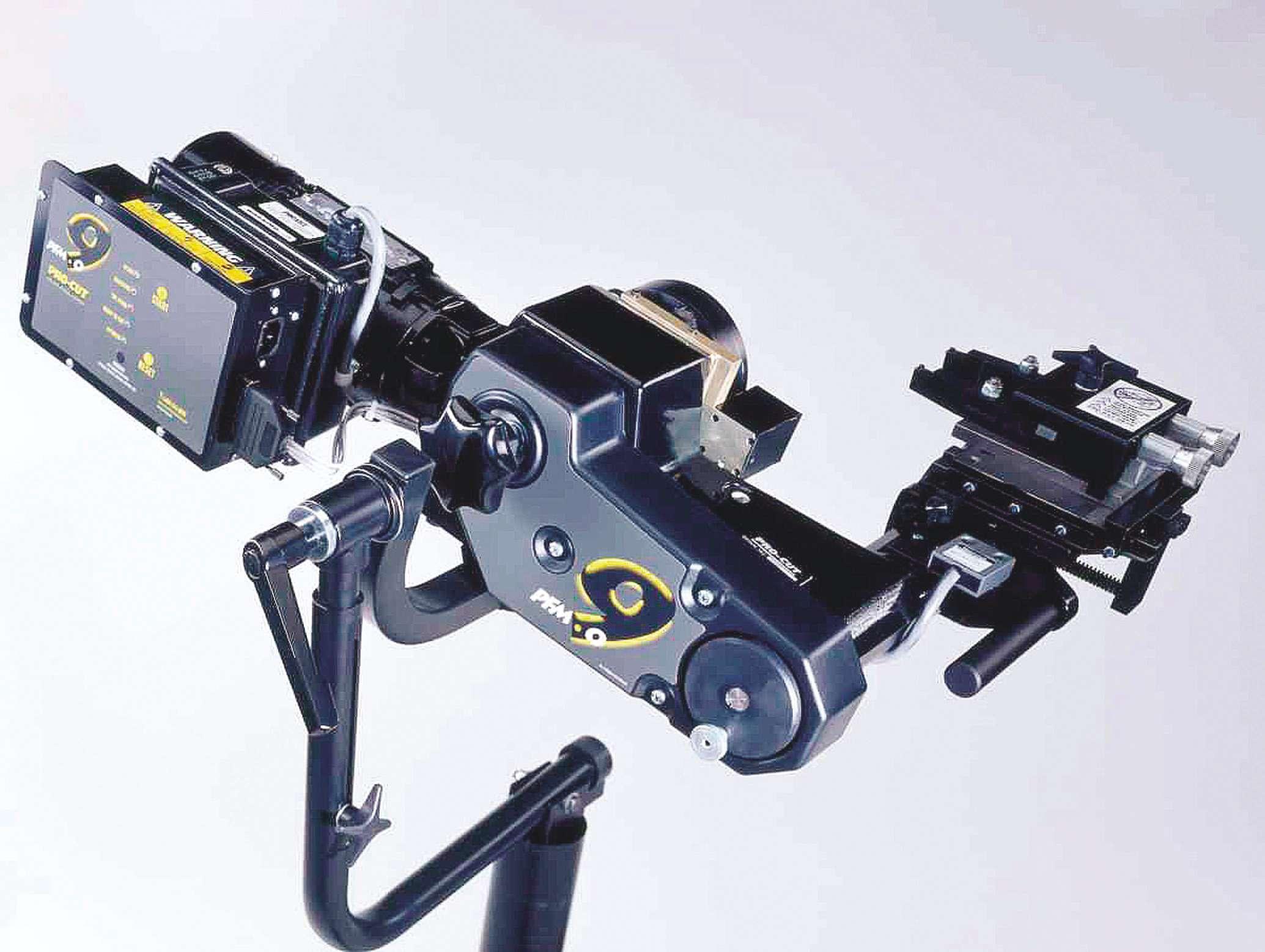
In order to conduct lateral runout and thickness measurements, a dial indicator and thickness gauge are mandatory. The dial indicator requires a mount that will attach rigidly to a nonmoving surface, such as the fexible-locking mount shown here. While a common micrometer can be used to measure thickness, a specialty rotor thickness caliper such as the one shown here features one pointed anvil and an opposing fat anvil, for more accurate measurement.
of uneven or over-tightening of the wheel fasteners, can easily create a pulsating brake pedal. Aside from the annoying feel of this, if the pedal is pulsating/bouncing, this means that the pads are not in a consistent full contact with the disc surface, which results in a varying contact patch between the disc and pad, which reduces braking effciency. Measuring lateral runout is a simple process, and there’s no reason to avoid the task.
With the wheel removed, install all of the wheel fasteners to secure the rotor to the hub. Installing only two or three fasteners can result in an erroneous runout reading. This is especially critical when dealing with thin-hat rotors. Uneven and incomplete defection at the hub can easily result in warped discs that display excessive runout.
Always install and fully torque to specifcation all of the wheel’s fasteners. In order to avoid damaging the nut seat surfaces, it’s also a good idea to install conical washers between the nuts and rotor hat surfaces.
As an example, by installing only two nuts on a fve-bolt hub, you might obtain a runout reading of, say, 0.005-inch. By installing three nuts the reading might be 0.003-inch. But by installing all fve, the reading may be 0.002-inch, which would be within spec.
Mount a dial indicator to a stationary area that doesn’t move in relation to wheel rotation (frame, strut, etc.). Dial indicator mounts are available with magnetic bases or clamp-on designs. Position the dial indicator’s plunger at 90 degrees to the disc surface, and push the plunger in to provide about 0.050-inch preload. Then zero the

Whenever checking rotors for lateral runout, always install all wheel fasteners and torque to specifcation. Installing only a few fasteners can easily result in a mis-reading that can indicate a runout issue where none exists. You must duplicate the installed wheel condition.

gauge face. The plunger should feature a small roller bearing at the tip to provide a consistent reading. The plunger tip should be placed about 1/2-inch inboard from the outer edge of pad contact. Slowly rotate the rotor and locate the low spot, then zero the gauge again.
Using a Sharpie, make a reference mark on the disc at the lowest reading location.
Slowly rotate the rotor, observing the gauge, noting the highest reading. The difference represents the amount of runout. Vehicle manufacturer specifcations may vary, but as a rule of thumb, the maximum allowable runout is about 0.002-inch to 0.001-inch for most applications.
Depending on the rotor design, you may be able to correct for runout using an on-car lathe, or you may need to simply replace the rotor. However, before replacing a rotor that you suspect of having excess runout, make a matchmark on the rotor hat and a corresponding wheel stud, then remove the rotor and reinstall at the next clockwise position and re-check runout.
You may have a situation where tolerances between the rotor and the hub are creating the excess runout. Continue to relocate the rotor on the hub, checking runout with each change.
You may be able to install the rotor with the high point of the rotor aligned with the low point of hub runout.
Measure disc thickness, but avoid making any decision based on only one measurement location. Measure for disc thickness in

Seen here is a specialty micrometer designed for rotor thickness measurement. The combination of one pointed and one fat anvil provides a more accurate measurement as opposed to a traditional micrometer that has two opposing fat anvils.

eight locations. Refer to the minimum service limit (this should be visible on the rear cavity of the rotor hat). Even if one measurement location is within the allowable thickness, measuring for thickness variation at several spots may locate a thickness that is too close to minimum. This is sort of a
double-check of fndings that result from checking runout.
Generally speaking, allowable thickness variation should be no more than 0.0002- inch (some OEs may spec a tolerance range of 0.001-inch to as little as 0.0004-inch).
It’s best to monitor both runout and thickness variation at the same time.
Checking lateral runout and thickness variation applies to all vehicle applications, and should not be limited only to vehicles that exhibit a brake pulsation issue.
All rotors should indicate minimum acceptable thickness, as this example that displays a 16 mm minimum thickness. Hot spots
In the days of old (not that long ago), brake pads were made of relatively soft materials that contained asbestos and other material mixes. They tended to wear the rotor evenly. Today, many pad materials contain ceramic, designed to transfer a

Ideally, if rotor disc resurfacing is required, this should be accomplished with an on-car lathe. This eliminates variables such as potential hub runout. Once machined, the rotor must always be installed in the same clock position. If an on-car lathe is used, be sure to place matchmarks on the rotor hat and hub to avoid stack-up of lateral runout. small amount of pad material to the rotor. If the rotor has no excess runout, the transfer is evenly deposited on the disc

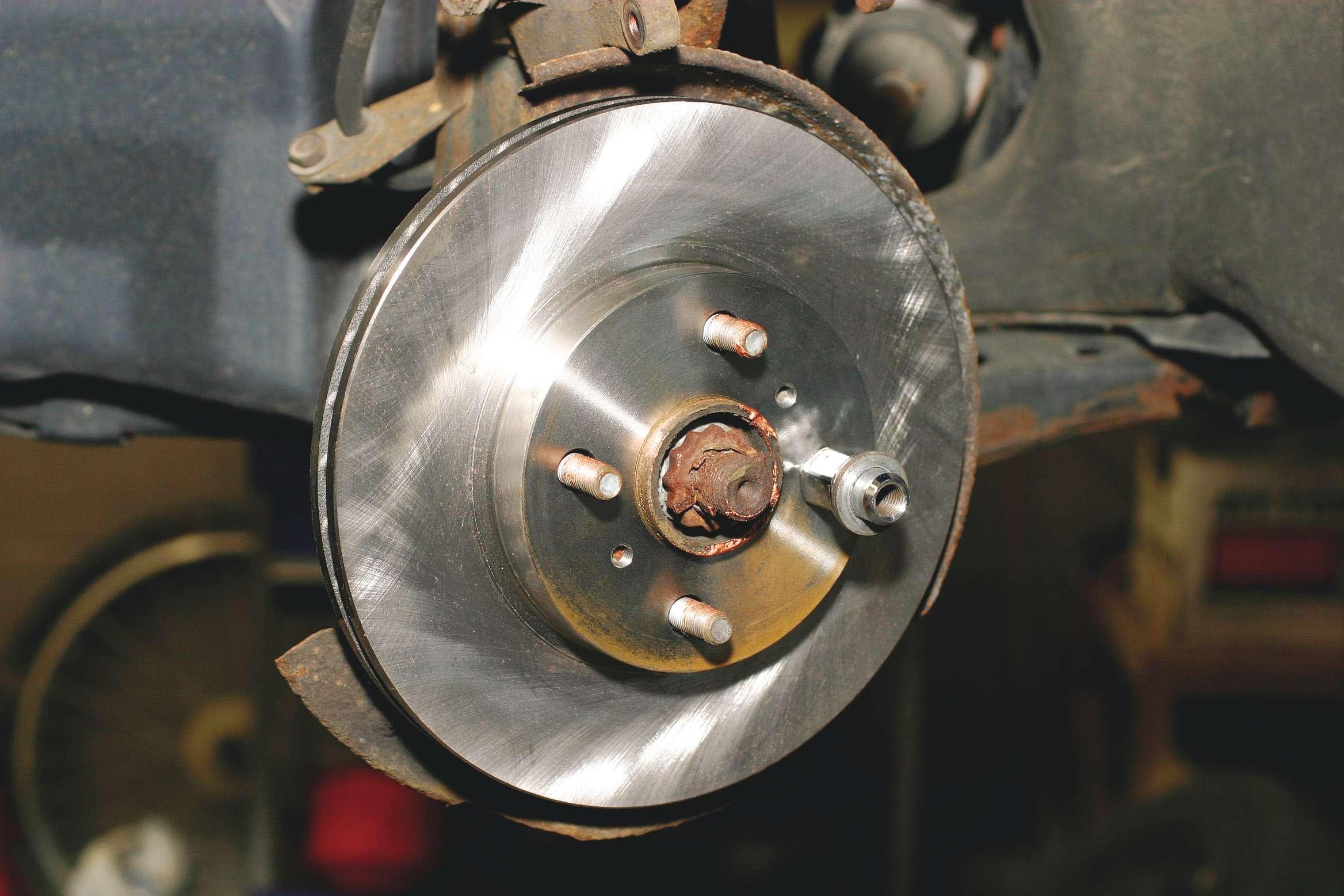
Cleaning rotor hat faces by removing rust buildup is critical to promote a fush-mount of the wheel to reduce the chances of lateral wheel runout, but caution is needed. The use of a wire brush is a safe option, while using a power tool and an abrasive disc requires great care, since a too-aggressive approach can cause an uneven surface and resulting runout. face. If the rotor has excessive runout, the transfer takes place unevenly, resulting in higher build-up at the point(s) of higher runout. This results in varying degrees of friction between the pad and rotor (causing a “slip-stick”).
The excess, or uneven buildup, can also be caused by improper caliper piston return, rusted or sticking caliper slides or even worn/loose hub bearings. If you see uneven bluing wear on the discs, suspect this uneven pad transfer, resulting from too much runout or the aforementioned caliper issues.
Remember: Excessive rotor runout can be caused by worn or loose hub bearings and may not be caused by the rotor itself.
Rotor coatings
Everyone can agree that a rusty rotor hat looks horrible on vehicles that feature wheels that allow the rotors to be visible. Yes, you can paint the rotor hats with a high temperature paint (paints are available

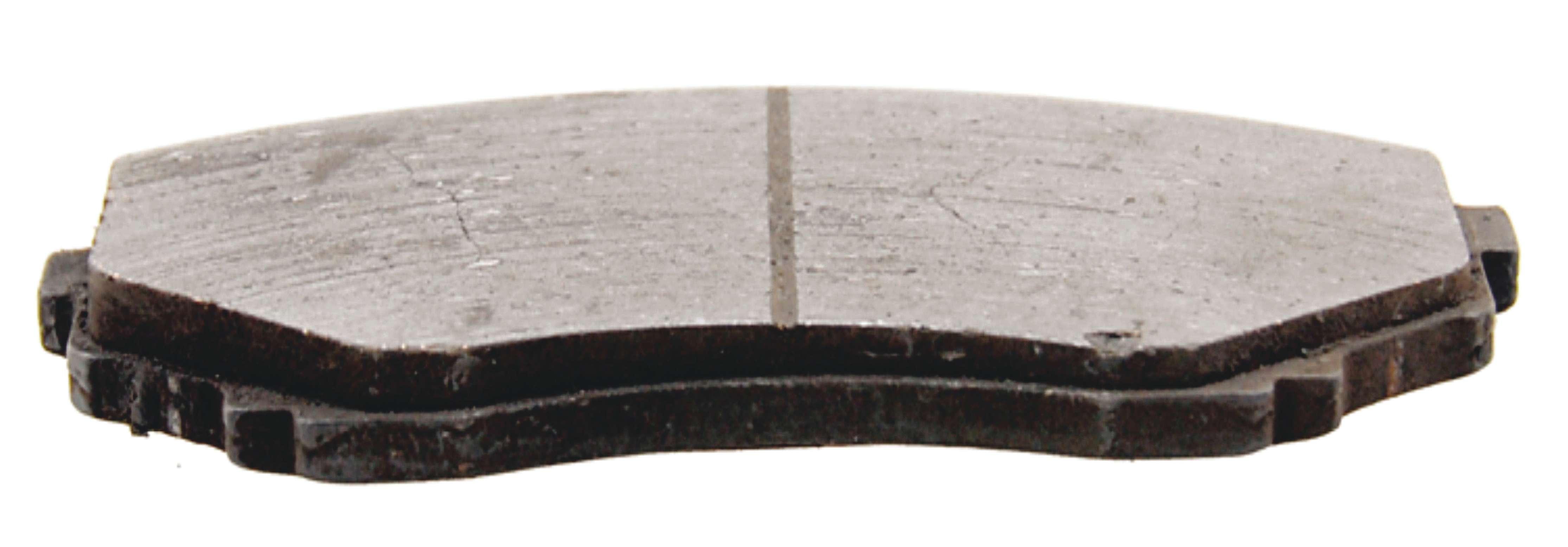
A cracked rotor indicates a poorly manufactured rotor that was improperly cast with impurities and or poorly heat treated. This is yet another reason to avoid bargain-basement rotors. that are designated as “brake paint”), but I’ve tried several brands and have never had long-term success. Eventually, surface rust will appear.
Today, various rotor manufacturers offer rotors that feature coated hats (coatings vary; some are powder coated, some are ceramic coated, and some are coated with a “proprietary” process) that does provide long-term rust prevention. Calipers
Obviously, caliper pistons must be compressed in order to allow room for the installation of new pads. Avoid using large channel lock pliers to push a piston. This can cause the piston to slightly cock in its bore, and you stand a chance of burring the piston contact face. Always use a dedicated piston compressor tool that provides a full-width fat face against the piston. In cases where the original pads have been severely worn down to minimum thickness, the piston(s) have been operating beyond their intended bore path. Foreign material, road debris, rust, etc., can build up on the piston walls. Pushing the piston fully back into its bore can result in lodging debris in the bore, resulting in a sticking piston that isn’t able to freely travel within its bore.

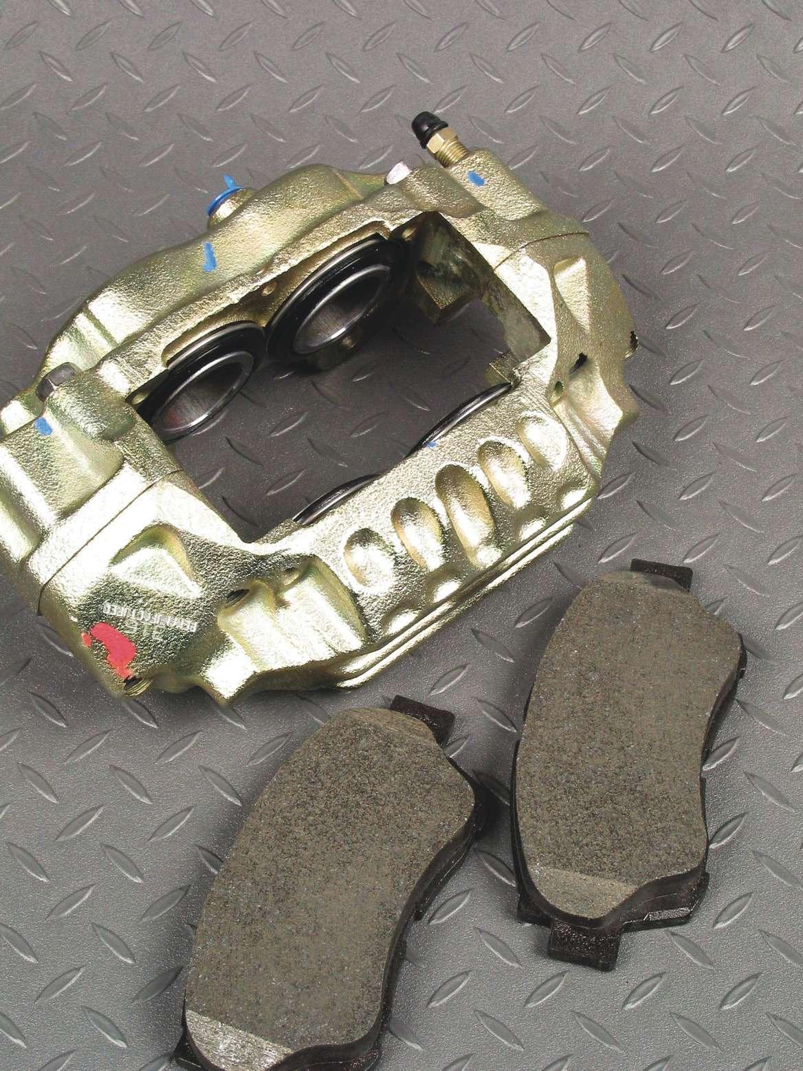
Extreme-duty emergency vehicles require optimum braking performance and consistent reliability. Whenever servicing any emergency vehicle, such as a police car, don’t scrimp on rotors or pads... always use the specifc materials specifed for the application.

In cases where pads have been allowed to wear dangerously thin, closely inspect the piston(s) and boots. If the pistons cannot freely run through the intended bore path, it’s best to simply replace the caliper. Of course, rebuilding is often an option, but considering the relatively reasonable price of reman calipers as opposed to the labor involved in rebuilding in-shop, replacing the calipers is usually the best route both in terms of expense and shop time.
Before rebuilding or installing new or reman calipers, always check the bleed valve frst, to verify that it threads easily. You want to avoid going through the time involved in caliper and pad installation only to fnd out that you have a problem with the bleed valve as you begin to bleed the system. Also, check the hex size of all bleeder valves before you begin installation. It’s common, especially for some remanufactured calipers, to have bleed valves that feature a different hex size. Knowing that you have the correct line wrench(s) handy from the start will save time and aggravation.
In some cases, during the remanufacturing process, correcting damaged bleed valve female threads may have resulted in re-machining to a larger size, which may change the size of the hex (for example, original calipers may have featured bleed valves that require a 10 mm line wrench, but the reman caliper may feature a bleed valve hex size of 5/16-inch, etc.). Check this from the start to avoid the need to travel back and forth to your tool chest.
Sliding calipers that ride on smooth-wall guide pins must be inspected for cleanliness and smooth engagement of the pins to their bores. If guide pin boots are damaged, this is a clear indication that the pins are
probably scored or rusty. Simply replace with new pins and new boots, applying a thin coat of high-temperature caliper pin grease prior to installation. Never install guide pins dry. If a caliper is not properly aligned to the rotor, this can result in dragging brakes. Caliper misalignment is usually caused by a distorted caliper bracket or severely warped rotors.
Master cylinders
When you encounter a low, sinking or spongy brake pedal, one suspect is the master cylinder. The cylinder may be bypassing, allowing fuid to leak past the piston seals internally, preventing a pressure buildup. This applies to all vehicles.
Master cylinders feature lip cup seals. This Calipers that feature pistons on opposing sides, such as the fourdesign allows for the piston caliper shown here, feature a fxed mounting position and do seal to improve as the not slide on a bracket. If uneven pad wear is found with a fxedmount caliper, suspect one bank of pistons for sticking issues. Also pressure increases. check the pad backing plate clearance to determine if one pad is
Another feature of dragging on its guides, preventing proper pad alignment and return. this seal is that it does not create a vacuum when the piston procedure for master cylinders is done at retracts. low pressure. Lip cup seals are more likely
As the pedal is depressed, the piston is to fail under low pressure. pushed in the forward direction. The lip cup Perform an isolation test. Use the proper seal, attached to the primary piston, genertool that won’t damage the fexible hydraulic ates pressure in the primary chamber frst, brake hose, clamp off all brake hoses. Press which in turn, forces the secondary piston down on the brake pedal, and if the pedal is forward, building pressure in the secondary low or spongy, remove the brake lines from chamber. As the pressure increases in both the master cylinder, and install threaded chambers, the edges of the seal are pressed plugs in the outlets (not plastic plugs). against the bore of the master cylinder. As Press down on the brake pedal and release pressure increases, sealing is improved. the pedal and wait approximately 10 seconds.
In the manufacturing process, the testing This allows the quick take-up valve to open

Prior to replacing pads, the caliper pistons must be retracted in order to provide room for the new and thicker pads. Never use channel pliers directly against the piston surfaces. Place a spare pad against the pistons and use a C-clamp to compress, or use a dedicated piston compressor tool that engages the pistons with a fat plate.

and the air to escape through the master cylinder compensating port, and the fuid in the reservoir to enter the bore of the master cylinder. Once air stops coming up into the reservoir, or the pedal becomes frm, apply light pressure to the pedal, and observe if the pedal continues toward the foor.
When the master cylinder ports are plugged, and the air is bled out of the bore, the pedal should be high and hard under low pedal or high pedal effort. If the pedal sinks under either condition, the seal is damaged and the master cylinder should be replaced.
ABS glitch after hub replacement? Here’s a useful tip from Raybestos. This applies to all ABS-equipped vehicles. The ABS light may be on and/or false ABS activation may occur following wheel bearing hub replacement on only one side of an axle.
If you diagnose a bad hub bearing on one side of a vehicle and the ABS wheel speed sensor or tone ring is integral to the bearing, you may need additional repairs to restore proper ABS functioning. In many cases, replacing one hub bearing will cause the driver to feel ABS false activation when coming to a slow stop on dry pavement.
False activation is usually described as a pulse in the brake pedal when not expected. The pulsation comes from the ABS valves cycling the supposedly lockedup wheel. This is due to the difference in signal strength from the wheel speed
Tapered pad wear indicates caliper misalignment and is not to be blamed on the pads. Closely inspect the caliper mounting to check for a bent bracket, debris or faulty hardware that causes the pad to be cocked and not parallel to the disc surface.
sensors (WSS) side to side. The problem is usually associated with air gap difference or wiring and/or connector integrity.
In many cases, removing the WSS from the other side, if possible, and cleaning the mounting surface may repair the problem. The rust build-up actually lifts the WSS from the bearing, increasing the air gap and weakening the signal. Another possible issue is play in the bearing causing sine wave frequency change and or AC voltage variation. The new bearing will have little to no play, while the remaining hub has acceptable play but can still affect signal strength. Again, the difference in signal from side to side may be enough to trigger false activation. If WSS

Uneven pad wear, where the pads on the same axle show different rates of wear, indicate a sticking caliper, where the caliper is not able to respond and return properly, causing one pad to wear more quickly. Pad wear should be viewed as a diagnostic element. Instead of blaming the pads, look for the cause of the uneven wear. is integral and not serviceable, replacing the hub bearings in pairs may be the only answer. The ABS system is activating as designed, so no warning light will be illuminated in most cases. At least discuss this with the customer to prevent unnecessary surprise repairs in the future and prevent the dreaded “It never did this before you worked on it” conversation.
In some cases, the issue may not be caused by an air gap concern. Citing certain 1996-2005 Audi models as an example, the ABS light may be on under light braking when the wheels are not locking up. Check for damaged wheel speed sensors or mismatched tires. Out of specifcation wheel speed sensor air gaps are not the likely issue. The most likely problem will be tiny cracks in the ABS tone rings found at the outer CV joint, or inside the rotor or wheel hub.
The best way to identify a crack or damaged tone ring is to use a lab scope. With the scope attached to the sensor, turn the ABS ring. A normal wheel speed sensor will show a smooth, round, uninterrupted sine wave that increases in amplitude and frequency as the wheel speed increases. If a crack in the tone ring is present, a notch or a fat spot on the wave form will be present.
If a scope isn’t available, clean the tone ring and inspect carefully with a bright light. Cracks normally form at the base of the teeth. ●


