18 minute read
Gasoline direct injection

from Auto Service Professional - April 2018
by EndeavorBusinessMedia-VehicleRepairGroup

Gasoline direct injection systems
Diagnosing and servicing GDI
Gasoline direct injection (GDI) introduces the fuel charge directly into the combustion chamber instead of via an intake runner. GDI systems differ in terms of operation and operating voltages. Servicing these systems involves diagnostic and repair challenges and precautions unique to GDI. In this article, Bill Fulton offers insight to aid in understanding these issues.
By Bill Fulton
For those of you who can recall when the manufacturers first came out with the port fuel injected systems, you will remember it wasn’t long before we saw some predictable problems surface on these vehicles, such as olefin and diolefin buildup on the pintle area of the injector causing a restriction.
We have all done the chemical cleaning process through the injector rail to improve or eliminate the common lean conditions. In addition, carbon buildup on the back of the intake valves was also a common problem. If you can recall, the European manufacturers used a walnut shell blasting unit to clean these valves.
With the introduction of deposit resistance injectors (DRI), the pintle restriction has been greatly improved, but not completely eliminated. Due to the efforts by the American Petroleum Institute (API), the Society of Automotive Engineers (SAE) and the Environmental Protection Agency (EPA), modern-day toptiered gasoline detergent additives have been increased to nearly eliminate this problem.
Have you noticed over the last few years that
when the OE manufacturers come out with a new system, there always seems to be new problems that surface over time and mileage? That’s truly the case here when addressing the modern-day gasoline direct injected (GDI) systems. But before we address these predictable problems, let’s look at the dynamics of these systems.
The fuel tank
Let’s begin at the fuel tank. There is a low side supply side and a high pressure side of the GDI systems. There are two systems known as mechanical returnless systems and electronic returnless systems. On the mechanical returnless systems the supply side fuel pressure regulator is in the tank and part of the fuel pump module. To my knowledge, GM is the only manufacturer that still supplies a conventional fuel pressure test port to check for low side supply pressure with the conventional fuel pressure test port. Go figure. Ford supplies some through model year 2010, only to eliminate it in model year 2011. A T-fitting adapter can be purchased from the OTC people to manually use your conventional fuel pressure test gauge. Normally, the low side supply pressure will usually range between 50

Circle 107 on Reader Service Card
to 60 psi. The interesting thing is that the GDI systems are designed to actually start and run from low side pressure, albeit not very well.
Even before returnless systems were introduced, the probability of having a fuel pressure test port has decreased over the years. If you can recall, the Honda PGMFI systems had a tab in the fuel pressure pulsator that would extend when system pressure was reached. On other systems it was truly a challenge to figure out how to manually test fuel pressure.
On the Ford electronic returnless systems, there is no fuel pressure regulator. Fuel pressure is controlled electronically by a fuel pump control module. The control module hammers the pump with system voltage or ground side controls the pump at 9,500 times a second. The PCM sees the engine load and increases the duty cycle signal to the fuel control module circuit.
The GM fuel pump control module will supply system voltage to the pump at 25,000 times a second. When the fuel pump control module wants to increase the low side pressure it simply increases the on time on a duty cycle scale to the pump. At any engine load condition the frequency signal never changes, but the duty cycle signal will increase as engine load and demand for low side fuel pressure increases. The PCM reads the engine load and uses the bus circuit to communicate
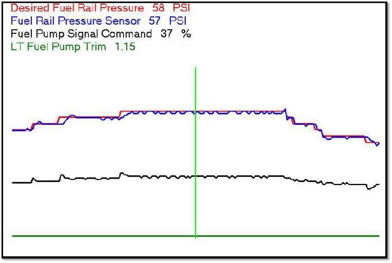
Figure 1: Fuel trim. Having numbers above 1 means that the fuel pump control module is increasing the duty cycle command to keep the low pressure readings within spec. Numbers below 1 indicate that the fuel pump control module is reducing the duty cycle signal to keep low side fuel pressure within spec. this duty cycle signal to the fuel pump control module.
These duty cycle signals can be seen from the scan tool. As engine load increases so, too, will this signal. In addition, on GM systems there are two new scan tool parameters that are valuable in detecting weak or bad fuel pumps. They are known as short term fuel pump trim and long term fuel pump trim. If all is well on the low pressure supply side the values will be very close to 1.
Having numbers above 1 means the fuel pump control module is increasing the duty cycle command to keep the low pressure readings within spec.
Numbers below 1 indicate that the fuel pump control module is reducing the duty cycle signal again to keep low side fuel pressure within specs (see Figure 1).
The Ford electronic returnless systems also use a fuel pump control module. The Ford PCM reads the engine load and communicates a fuel pump control (FPC) signal in a duty cycle scale. For example, let’s say at idle under no-load conditions, your scan tool indicates a 30% duty cycle command from the PCM to the fuel pump control module. The Ford fuel pump control module will internally double this value and turn the pump on 60% on and 40% off. The voltage to the pump from the fuel pump control module is sent at 9,500 times a second. Ford fuel pumps are either ground side controlled or feed side controlled by the fuel pump control module. Obviously, as engine load increases, the duty cycle signal is increased but the frequency signal remains constant. On both Ford and GM systems the fuel pump control modules have the responsibility of detecting electrical faults and relaying these to the PCM. The Ford systems use a dedicated fuel pump monitoring (FPM) circuit to communicate these faults. The GM systems will use the two wire high speed bus circuit for communication between the PCM and the fuel pump control module. The good news is that on these electronic returnless systems, there is a three-wire low pressure sensor that reports low side fuel supply to the fuel pump control module, meaning that we can read this value from the scan tool.
side fuel rail pressure to the PCM. This PID is available on the scan tool. The scan tool will show the command signal to the control solenoid. GM shows this on-time in degrees of crank rotation, although I have seen some aftermarket scan tools convert this to a duty cycle scale (see Figure 3). The top scan graphic is the duty cycle signal from the PCM to the high pressure pump control solenoid in a duty cycle scale. The bottom scan graphic is the command to the high presFigure 3: The top scan here shows the duty cycle signal from the PCM sure pump control solenoid to the high pressure pump control solenoid in duty cycle scale. The bottom graph shows the command to the high pressure pump conin degrees of crank rotation. trol solenoid in degrees of crank rotation. At frame 10 we performed At frame 10 we did a WOT a WOT power brake. Note the increase in both parameters. power brake. Note the increase in both parameters. condition. Note that the high side pressure Ford and other manufacturers show this value reached 9.8 mega pascals. The conversion to in a duty cycle scale. psi is to multiply 9.8 X 145 equals 1,421 psi. Depending on your scan tool you may be Under WOT conditions at 5,000 rpm this able to bidirectionally control this solenoid pressure will exceed 2,000 psi. by commanding a higher on-time which
The supply side system supplies low side fuel should increase the high side pressure. Keep pressure to the high pressure pump that is in mind you will have to bring up the rpm as driven from the camshaft. This high pressure you use this function in your bay. The control pump has an integrated control solenoid that solenoids have very low resistance values, is controlled by the PCM. The solenoid is around .5 ohms, so the PCM will hammer the spring loaded open, and duty cycle controlled solenoid 6,000 times per second (on/off) to to close in order to raise high side pressure in limit the current flow. the injector rail. As with the fuel pump control, the PCM
Ford uses four lobes on the camshaft simply increases the on-time to ramp up high whereas the other manufacturers use three side pressure. The PCM on both systems lobes on the camshaft. A cam follower is supply both the voltage and ground for these used to mechanically connect the pump to solenoids. The circuit codes for these systems the camshaft. When removing the pump are very robust. To limit the current flow the always remove the cam follower and check signal is frequency controlled by the PCM. On for concave signs of wear where most likely GM vehicles if the high side pressure line is the cam lobes are worn as well. This would removed, replace it and do not reuse it. Ford prevent full piston travel of the pump, thus says that if the high side fuel pressure sensor is creating a loss of fuel pressure on the high removed, it must be replaced with a new one. side. This problem is well documented on Lean conditions are a common problem some European vehicles. from a bad high pressure pump. In addition
In addition, a high side fuel pressure sensor there have been cases where the high pressure mounted on the injector rail reports high pump leaks fuel into the crankcase, so always

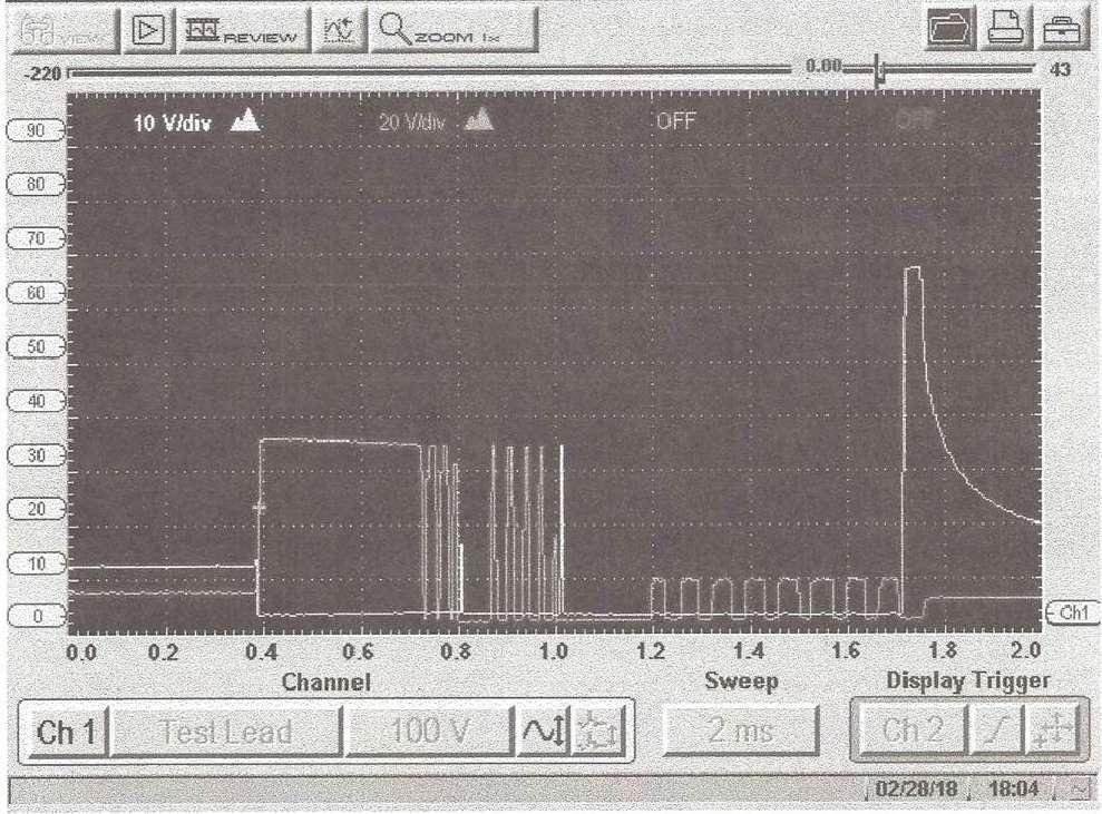
check the oil level on these systems. Before and negative fuel trim corrections. In this breaking any fuel lines on these systems, case, by unplugging the vacuum source and either remove the fuel pump fuse or remove noting fuel trim values corrected verifies a the fuel pump relay and crank the engine over leaking sensor. until the engine stalls and high fuel pressure On the GDI systems, the injectors cannot is relieved. operate with 12 volts as in conventional
Before Ford came out with their GDI PFI systems. The injectors are charged by systems, they were using electronic returnless capacitors inside the PCM with 65 volts. Two systems as early as 1998. On the injector rail injectors are charged at a time but only one is a three-wire fuel rail pressure sensor. It injector is supplied with a ground by the PCM also had a vacuum line hooked to a manifold via the sequential firing order of the injectors. vacuum source. The engineering idea here is When diagnosing a no-start, where you that the PCM can see the exact fuel pressure have ignition and fuel pressure, the need drop across the injectors. The rule is that for to check the injector drive circuit would be every 2 in. of vacuum, the tips of the injecnecessary. Noid lights and test lights would tors that are exposed to it will increase the not work. In addition, access to the injectors pressure drop across the injectors 1 psi. For would require a top engine tear-down. example, at 18 in. of vacuum, the pressure The easy access would be at the PCM or at drop across the injectors will increase by 9 the wiring harness. When viewing a voltage psi. If the rail pressure reads 35 psi, the scan trace, a two-channel scope would be needed. tool will read 44 psi. The fuel pressure gauge One channel would go to one wire to the readings and the scan tool fuel pressure injector while the other channel lead would readings will never be the same. One problem go to the other wire. we have seen on these systems is that the During cranking you would see 65 volts sensors are known to leak fuel pressure into on both channels. When the PCM wants the its vacuum source, causing rich conditions injector to be energized, the PCM will again supply the ground (see Figure 4). A low inductive current probe was clamped around the injector control wire. The amperage values on these GDI injectors vary between 8 and 12 amps. On this GM GDI system peak current flow reached 12 amps before the PCM modulates the ground to limit the current flow. The voltage trace on the right shows that the PCM capacitively charged the injector with 65 volts. The resistance values of the GDI injectors are very low in the range of 1.5 ohms. Removing Figure 4: When the PCM wants the injector to be energized, the the injectors will require PCM will again supply ground. A low inductive current probe was a small slide hammer tool. clamped around the injector control wire. The amperage values on these GDI injectors vary between 8 and 12 amps. On this GM GDI In addition, a bore brush system, peak current flow reached 12 amps before the PCM moduwould be needed to clean the lates ground to limit current flow. The voltage trace on the right injector bore. Remember, the shows that the PCM capacitively charged the injector with 65 volts. injector is inserted into the

Circle 110 on Reader Service Card
combustion chamber, so you must replace the seal. A special tool is needed to install a new injector compression seal.
There are some common problems on these GDI systems that have started to surface. Number one is carbon buildup on the tip of the injector causing a reduced and distorted injector spray pattern resulting in a lean density misfire.
The number two problem is carbon deposit
Figure 5: Example of a GDI application. Notice the injector exposed to the combustion chamber between the two intake valves.

buildup in the combustion chamber which can raise the compression ratio and can glow red hot causing spark knock. Most modern GDI systems will retard spark timing per cylinder in the event that detonation is detected from individual cylinders. On GM systems you will have scan data for this problem from each individual cylinder.
The third most common problem involves carbon buildup on the back of the intake valves. Remember, we no longer have the solvent effect from fuel pulsed to the back side of the intake valves. This problem is caused by crankcase fumes from vaporized oil molecules sucked through the PCV system. Synthetic or semi synthetic oils reduce this possibility. Of course, we all have customers who neglect the recommended oil change intervals and the recommended specific type of oil.
The fourth problem becomes more serious, with carbon deposit buildup in the top compression ring land of the piston. This prevents the top compression ring from expanding, resulting in blow-by and loss of compression.
In my opinion, these problems can be adequately addressed by an extended chemical soaking. The idea here is to allow an extended soaking period, as in overnight, to allow the chemical to break the molecular bonding of the carbon.
Obviously, this will not remove all deposits, but by giving it an extended soaking period it will produce an improvement. For more info on this you may want to visit BGs website at www.BGprod.com. The BG people sell a three-can kit where one can is used to clean the injectors through the rail. The chemical known as 44K is sprayed through the intake to address the carbon buildup on the back of the valves. In extreme cases it will be necessary to remove the intake manifold’s upper plenum. Half of the intake valves will be closed. A few ounces of 44K are applied to the back of these intake valves. A minimum 15 minutes of soak time is needed. The kit comes with large wooden toothpicks to punch at the carbon and break it up.
In addition, a wire brush is also supplied to scrub the back of the intake valves. All of this can be viewed on BG’s website.
With the number of these vehicles increasing every year, these systems are going to come into your shop with some of these common problems. As it goes in our industry, “Show me a problem and I will show you an opportunity.”
Bill Fulton is the author of Mitchell’s Advanced Engine Performance Diagnostics and Advanced Engine Diagnostics manuals. He is also the author of several lab scope and drivability manuals. He is a certified Master Technician with over 30 years of training and R&D experience. He currently owns and operates Ohio Automotive Technology, which is an automotive repair and research development center.
Judy’s Automotive
Automotive service ‘with a woman’s touch’
Judy’s Automotive is located in historic San Rafael, Calif., in the North Bay region of San Francisco. The one-person shop opened in 2005 and offers maintenance and repairs for all Asian and American cars, light trucks and SUVs.
Mayne shared her background and work experience that led to opening her own shop.
“In 2005, I was granted an opportunity to purchase Cox Automotive, a successful business for 35 years. I worked for the owner back in the 1980s, and after keeping in touch with him over the years, he was comfortable with the transition. My former employers include North Bay Motorsports, Righetti Automotive, Heynneman European, Fairfax Garage and Excelsior Auto Clinic.
“My first job (after Jack-in-the-Box) was pumping full-service gas at Red Hill Shell in San Anselmo while in high school. I had a 1962 Chevy Nova and learned how to fix it. After attending Indian Valley College in Novato for two years and supporting myself with a job in Point Reyes as an apprentice
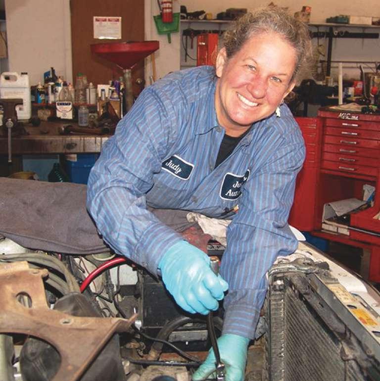
Owner and Master Tech Judy Mayne offers vehicle service “with a woman’s touch,” garnering close relationships with a loyal customer base.
technician, I enrolled in the two-year auto technology program and received my A.S. degree in 1981. I had a smog license up
Judy’s Automotive
San Rafael, California

Owner: Judy Mayne Business founded: 2005 Number of bays: 4 Number of certified technicians: 1 Shop size: 2,700 square feet Number of vehicles services per month: 60 to 70 Hourly labor rate: $120 Average spent on tools and equipment annually: N/A Vehicle makes serviced: Asian and domestic Website: www.judysautomotive.com
until 2000 when it all changed again. I have maintained my status as an ASE Certified Master Technician since then, returning to classes as needed to learn the new technology.
“I still have the Nova. It’s a red 1962 convertible, a popular fixture of the local scene, as I cruise the town with my dog, Angie, riding in the back! My shop is also a sponsor of the local Pacific’s Baseball Club and I give back to the community with regular donations to local schools and other non-profit organization silent auctions.”
NOTE: Mayne’s son, Kevin, shares shop space with Charlie Chappelle, specializing in BMW, Audi and VW as Chappelle Automotive. In combination with Judy’s domestic and Asian service, the addition of European vehicle service
has resulted in the shop location’s reputation for comprehensive brand coverage.
Judy’s Automotive offers general service/ repair for most systems with the exception of A/C Freon, and engine and transmission rebuilds.
Business philosophy
Mayne said, “I discount oil services in order to remain competitive and establish a relationship with the customer, performing a pretty thorough bumper-to-bumper The shop opened under Mayne’s ownership in 2005, offering service for Asian and domestic vehicles. Although a one-person operation, the shop has become well regarded in the relatively small historic bay-side area. I charge a full/fair price for major services and repairs. I can then keep notes and monitor for immediate or future services needed. I try to do my best to explain what, how and why specific services should be done. I do ‘little’ things for free, not always charging for something that took five minutes.
“The most difficult customer question to answer is typically, ‘How long will my car last?’ I politely decline an answer, proclaiming that’s outside of my human abilities, comparing it to ‘how long will any of us live?’”
Parts sources
Mayne noted that she sources parts from WorldPac and O’Reilly’s, based on “good service, quality merchandise and warranty support.
“I do try to educate customers about the value of quality parts. I politely decline installation of parts purchased by a potential customer. Even if they bought from a dealer,
I’d have to charge more to make inspection each time.

While servicing an average of only 60 to 70 vehicles per month, the shop’s attention to detail and development of personal customer relationships has created a successful niche in the area’s marketplace.
The shop promotes the theme of service “with a woman’s touch,” which allows the operation to stand out among competitors, Mayne said.
up overhead and I can’t provide an honest
warranty.”
Parts buying decisions
We asked, “On a scale of 1 to 3, with 3 of highest importance, what determines your buying decisions?” Mayne said:
Price......................................................2 Brand name recognition ..................1 Promotion in racing..........................0 Perceived quality................................3 Availability/time ................................3
What do your customers expect from Judy’s Automotive?
“Customers expect honesty and complete reports of all service work,” Mayne said.
How does Auto Service Professional
benefit your business?
“Sharing of information is vital, and I rely on ASP for detailed technical articles and announcements of new parts, tools and equipment,” said Mayne. “ASP offers superb education and information sharing.”
