15 minute read
DIAGNOSING ENGINE MISFIRE AND SURGE ISSUES

from Auto Service Professional - February 2021
by EndeavorBusinessMedia-VehicleRepairGroup


Start with the basics and work the problem one system at a time
BY EDWIN HAZZARD
HEN WE GET THAT ELUSIVE VEHICLE
Wthat has been at multiple shops or back to your shop multiple times for that intermittent or even that hardto-solve problem, it really tests our technician-trained minds to their core. If you like challenges but feel you are being mentally tortured by this type of vehicle, you’re not alone. There’s nothing worse than thinking that you have that vehicle fi xed and a couple of days later, it comes back. A technician friend of mine used to call this “the boomerang eff ect.” It goes out, only to come back.
Now in all fairness, not all vehicles return for the same problem. Sometimes it’s a communication breakdown between the customer and the service advisor or the service advisor and the technician. It possibly could be lost in translation. Those of us in the service industry take pride in the motto of “fi xing it right the fi rst time.” As technicians, we sometimes get led down that diagnostic path that has many diff erent paths from which to choose.
What steers a lot of technicians down the wrong path is how they approach the problem. Sometimes the fi x is so simple that it’s staring you in the face. But with so many “what-ifs” in the mix, they may overlook the obvious, akin to the old saying “You can’t see the forest for the trees.”
In this article, I’m going to discuss how to approach a vehicle that has a misfi re and how to diagnose the problem by keeping it simple. Keep in mind that this is how I do it. It doesn’t necessarily mean it’s the right way, wrong way or only way. It means this is what works for me and it may or may not work for you.
As technicians, we have all experienced an engine that is misfi ring at one time or another. I’m not going to go into great detail about how the combustion
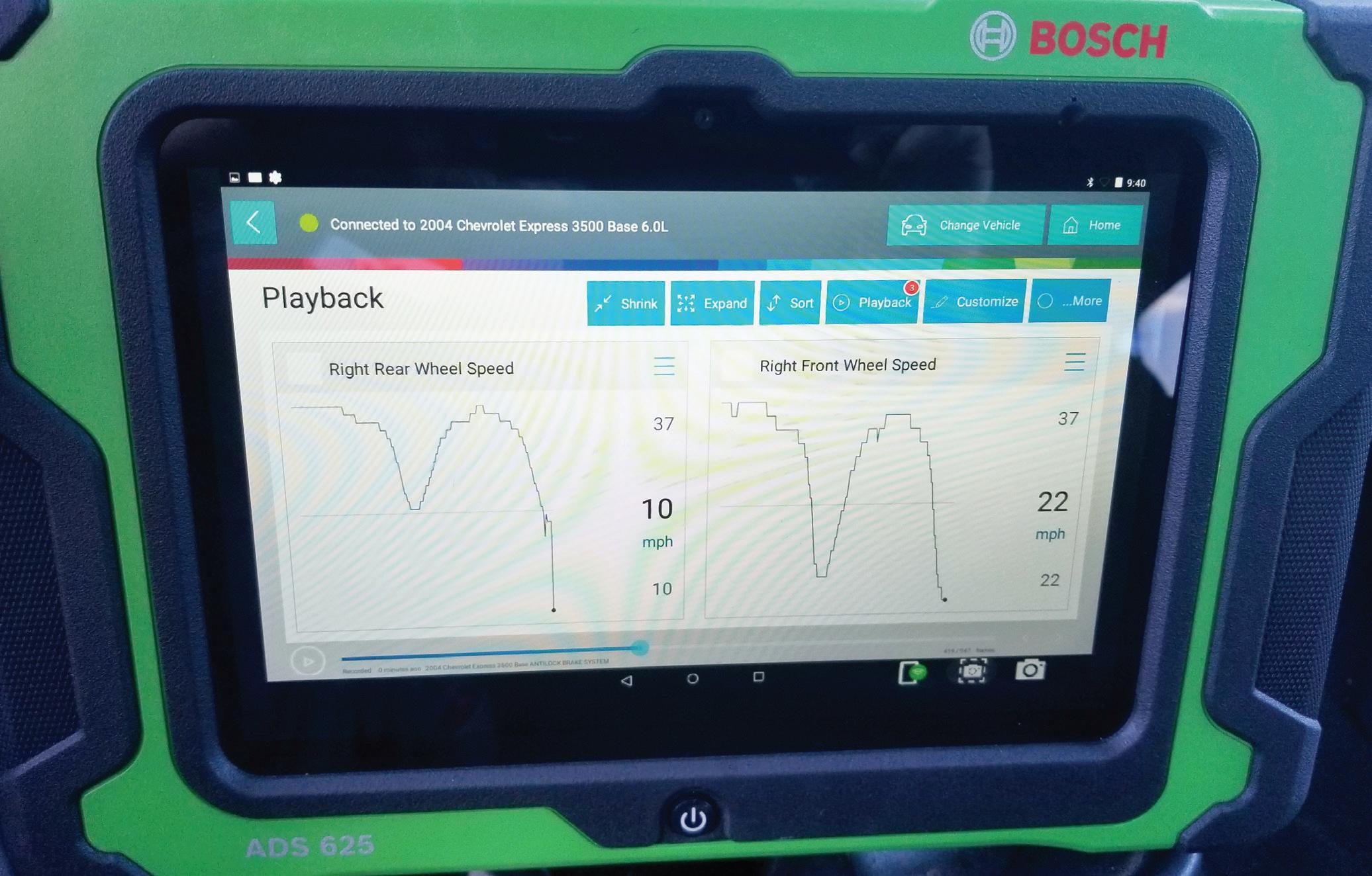
Fig. 1: You need to have a capable scan tool that is updated for the make/model/year vehicle at hand that also is able to provide live data.
process works as I’m sure most of you already know how it works, but keep in mind that there always has to be intake, compression, power and exhaust.
That’s just the way it is.
If one of these steps is missing, then a misfire will occur.
So where do you start? My recommendation is to verify the issue. What if it’s not misfiring, but cutting out? What if it’s surging? What if it’s not an enginerelated problem, but a transmission problem? Have you ever heard the term “chasing a ghost?”
Make sure the complaint matches the symptom. Once we have verified that the engine is in fact misfiring, let’s put a diagnostic game plan together.
When you diagnose a vehicle, it’s very similar to going to a gunfight. You want to be prepared and have the right weapons. First and foremost, you need to have a capable scan tool (see Figure 1). Now when I say
capable, I mean one that is updated for the vehicle that you are working on.
The tool should have graphing capabilities and also be able to read Mode6 data (see Figure 2 on page 14). The scan tool should also be capable of performing a recording, which can be done while you are driving or sitting in the service bay, plus have play-back capabilities. And the ability to take screenshots is always a plus.
A simple code reader with limited data will just make your job all that more complex.
Other tools that should be included are a digital volt ohm meter (DVOM) and/or a lab scope. There are many other tools than can be used, but I want to keep this as simple as possible.
Just as you verified the complaint, now you want to verify the data. Set up your scan tool to look at the data while the engine is misfiring. There’s a lot of data that can be shown, but you want to focus on the data that’s
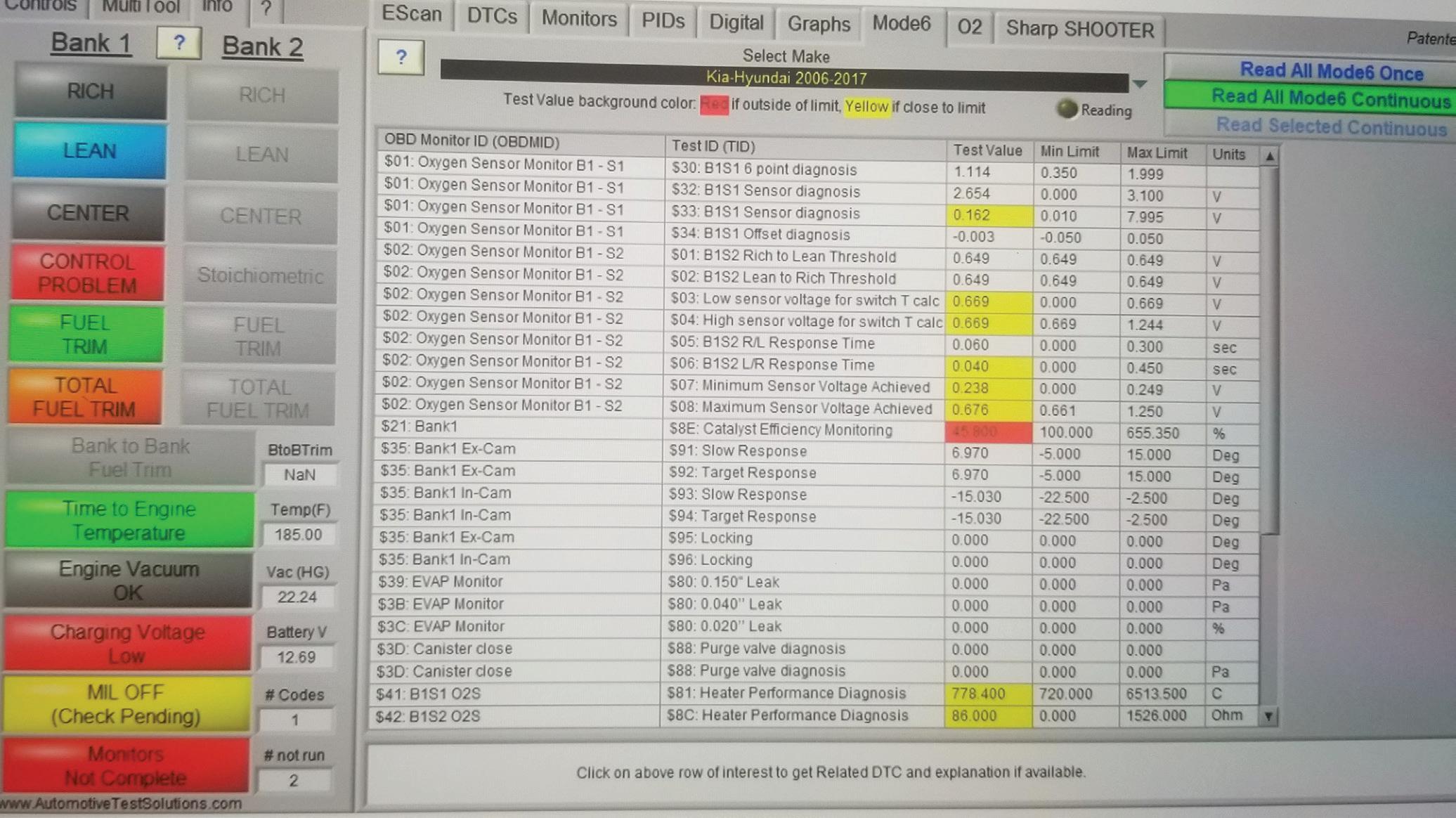
Fig. 2
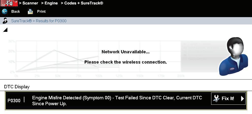
Fig. 3
important. If you have pulled any DTCs, then you know that’s probably one of the first clues you have toward pinpointing the misfire (see Figure 3). As a rule of thumb, I never erase the codes until the vehicle is fixed. If for some reason you do have to erase that diagnostic trouble code, at least save a screenshot of the code in case you have to revert back to it.
Let’s say for example that you pulled a DTC of P0300, which is a random cylinder misfire. That tells you that the computer has picked up the misfiring cylinder, but it hasn’t identified which specific cylinder it is. A lot of times, you will get a cylinder-specific misfire code, which will help you in some cases to narrow down which cylinder it could possibly be.
When I say “possibly,” that means it’s not always the case. I have seen a cylinder-specific code not misfiring in the cylinder that it flagged, so be careful that you’re not led down the wrong path. There could be variables, like a companion cylinder that is throwing off the cylinder with the code. Perhaps the crankshaft reluctor/ trigger wheel is damaged and the crankshaft position sensor is identifying the wrong cylinder.
Let’s take our P0300 code example as our only diagnostic trouble code retrieved. This is where a lot of technicians can become confused. The biggest issue is where do you start?
What we know is that the ECM has determined that a misfire has occurred. Looking at scan data may or may not give you any clues (see Figure 4 on page 15). Maybe the vehicle set this code a while ago and your scan tool
Fig. 2: The scan tool should feature graphic capabilities and allow you to read Mode6 data.
Fig. 3: This test failed because the current codes were cleared since the tool’s power-up.
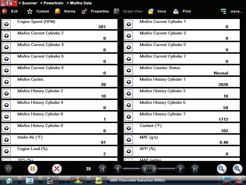
Fig. 4
data isn’t showing anything now. Maybe this code crops up every couple of weeks, but is not consistent.
While you have your scan tool connected to the vehicle, now is a good time to look at Mode6 data. Mode6 data can be very useful as long as the diagnostic trouble codes have not been cleared recently. A good way to check to see if that occurred is to check the drive cycle monitors. If the drive cycle monitors are incomplete, there’s a good chance the code or codes have been cleared. If a majority of the drive cycle monitors have been completed but some are still incomplete, that possibly could be a clue to your puzzle.
Getting back to the Mode6 data, pay close attention to misfire data. If your scan tool is capable of giving you the identification of the hexi-decimal data descriptions, you should see which cylinders have been misfiring and how often (see Figure 5 on page 16). Many technicians are not aware of the vast amount of information you can gain by looking at Mode6 data. Once you have identified the misfiring cylinders, this is where the fun begins. When a cylinder is misfiring, there are multiple reasons why this is happening.
The hardest part in diagnosing a misfiring cylinder is getting to the root cause of the problem. As I stated earlier, this is the way that I go about it. I like to keep it simple and basic in the beginning.
When I approach a misfire issue, I like to break it down into four possible choices. A cylinder misfire is caused by either a fuel problem, an ignition problem, a mechanical problem or an electrical problem. That’s it! Of these four choices, one or more can be the cause.
Most likely, it is just one of these choices. After looking at scan data — which consists of fuel trims, voltage readings or any data PID (on-board diagnostics parameter ID) that catches my eye and looks a little out of place — then I usually grab a screenshot for further reference. Once I get to this point, then it’s time to start looking at my four choices.
If the vehicle has a lot of miles on the odometer and I don’t have any useful service history, then I will start my testing by looking up the mechanical integrity of the engine. Remember when I said start with the basics? I want to know if the compression, valves, engine timing and/or engine vacuum are adequate. Any one of those can cause a misfire or even an engine surge.
There are many ways of performing these tests. One of the easiest and quickest ways to gather a lot of good information is to perform a cranking compression test. This test will give you a good idea of the integrity of the engine. Using a lab scope with an amp clamp around the battery cable is all there is to it.
Next up is to disable the fuel, or if possible, put the vehicle in clear flood mode, crank the engine for 10 seconds and catch a wave form. If your pattern is consistent all the way across, then your compression for all cylinders is likely good. If you have one cylinder or more that’s a lot different than the others, then you know something’s not right.
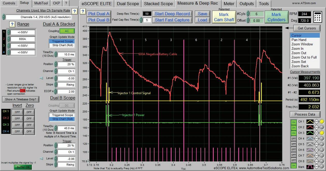
Use another channel on the scope, sync it to the cylinder and then perform the test again and you will see — based on the firing order — which cylinder is a problem cylinder. (see Figure 6 on page 16). That’s just one test you can perform.
You can always still perform a mechanical compression test, but with the design and often limited access of today’s modern engines, that can be tedious and time consuming.
Another mechanical test which happens to be fairly new technology is the in-cylinder test. This test is also performed with a lab scope and a pressure transducer. Removing the spark plug and installing the pressure transducer will give you a lot of information in a short period of time. In-cylinder testing can tell you what your compression is, when the
Fig. 4: Screenshot of misfire data. Note that cylinder 1 has a history of 2,826 misfires.
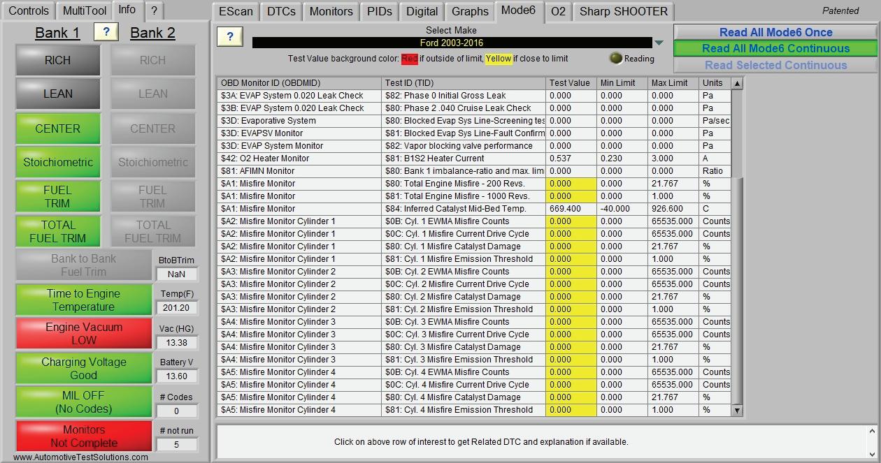
Fig. 5
valves open and close and if they operate at the correct time. There are a lot of training classes on this type of testing. It does take some practice, but once you become proficient at what you’re looking at then this test is invaluable.
The next choice to consider could be either a fuel problem or an ignition problem. Let’s start by testing the vehicle’s fuel system.
To isolate the fuel control system, you want to be able to interrogate the fuel pump, the fuel pressure, the fuel volume and the fuel injectors.
Again using your lab scope, you can check the integrity of the fuel pump to see if it’s working correctly and is producing the correct pressure. Hooking up your amp clamp to the power feed of the fuel pump and turning the fuel pump on will tell you the condition of the fuel pump motor by looking at the humps on your wave form for consistency (see Figure 8 on page 18).
Also, observing your amperage draw will tell you just how hard the fuel pump is working. Remember, if your fuel pump is weak, your fuel pressure and volume will be affected.
Other checks that can be done in the fuel system include checking the fuel injectors not only for fuel spray, but also for amperage. If you have a fuel injector that is electronically failing, this will give you a misfire, as well.
The checks that can be performed to determine the condition of an injector are to make sure you are getting the correct signal from the ECM, which is the amount of amperage that it takes to fire the injector, along with checking injector resistance.
Don’t forget — on GDI engines, you will have two fuel systems: a low pressure system and a high pressure system. Remember to use caution when testing a high pressure system, as the fuel pressure can be high enough to cause bodily injury.
Next, check the ignition system. These checks need to be made at the primary and secondary parts of the system. Checking the primary is done at the ignition coil. You’re going to check for the proper power and signal to the coil, along with the proper amperage. This also can be checked using your amp clamp and a lab scope. You want to be sure that you are receiving the correct signal to the ignition coil and you want to make sure that the coil is strong enough to provide the correct amperage to be able to fire the spark plug.
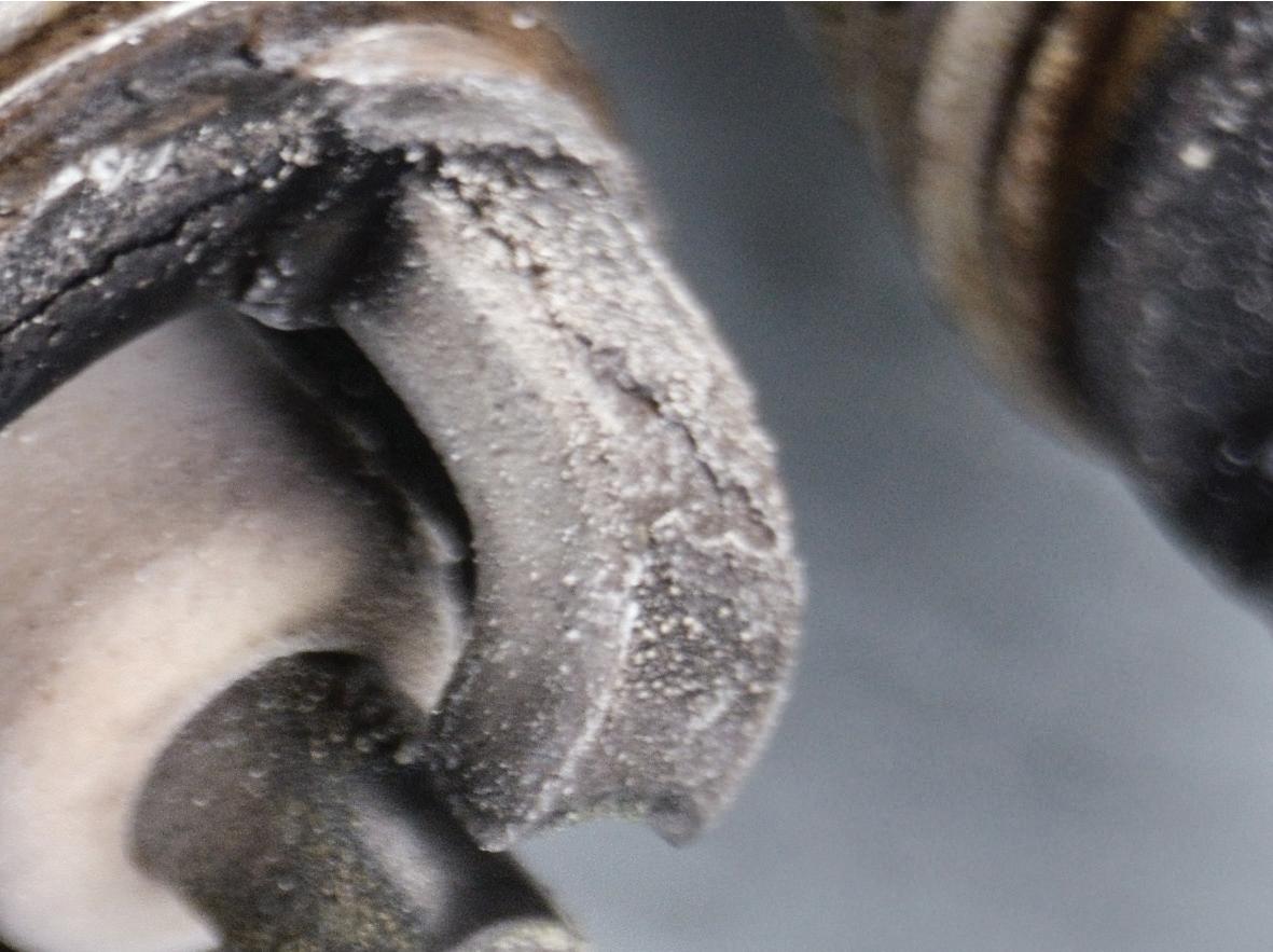
A good visual inspection of the secondary components — such as the cable and the spark plug boot, along with the spark plug itself — is important. Look for any irregularities, such as a boot that could be arcing to the cylinder head or the spark plug itself for being worn out. Also look for carbon tracking and possibly a cracked insulator during install (see Figure 9 on page 18). Take a good look at the spark plug and see how well it was performing. Look for fuel deposits, excessive oil wetness and spark plug gap.
Our last choice of tests is electrical. There can be a wiring issue, a connector issue, a voltage problem or a computer failure.
Checking circuits can sometimes be a tedious task. But it’s necessary. You want to make sure when testing your components, such as the fuel injectors or ignition coils, that you have the proper voltage and connections. Perform a good visual inspection of your connectors, making sure that connectors are seated properly and that the wiring terminals are making good contact with the component. I have seen a lot of problems that were caused by improper testing during prior repairs. Make sure that you test your components using approved methods. If not, you might create another problem without even knowing it.
When testing computer circuits, make sure that you understand what the computer is supposed to send and receive. It’s a good idea to look at your service information to see how the computer is used on the vehicle you’re diagnosing. I have seen a lot of computers replaced when there was actually nothing wrong with them.
Fig. 5: Yellow bars indicate the test value is near limit.
Fig. 6: Screenshot of a compression test synced to the number one injector. Note how the frequency depletes.
Fig. 7: Scope capture of an incylinder pressure waveform.
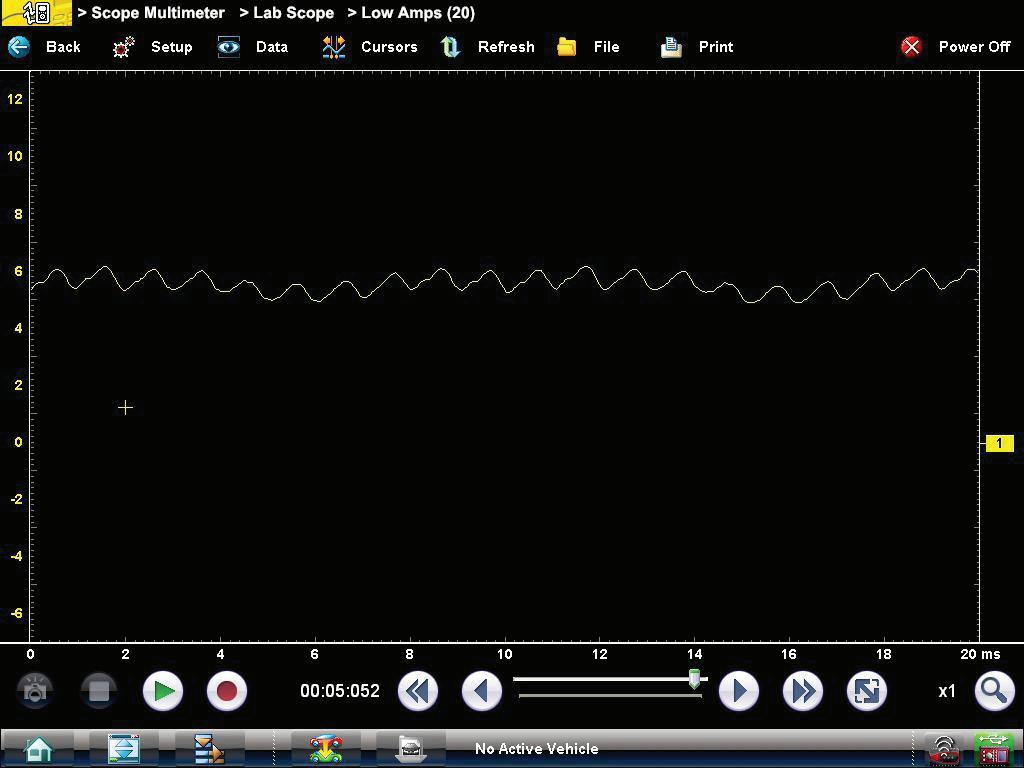
Fig. 7
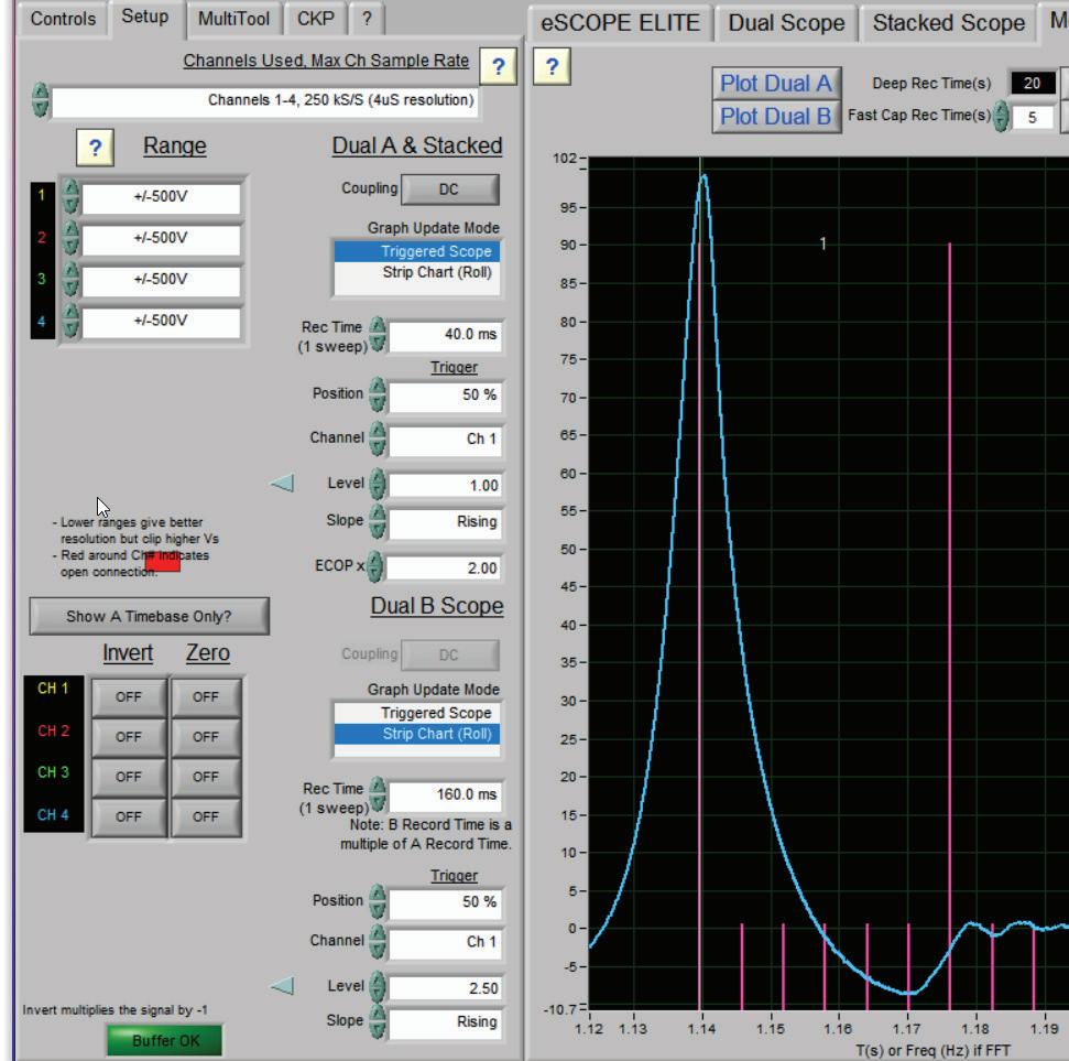
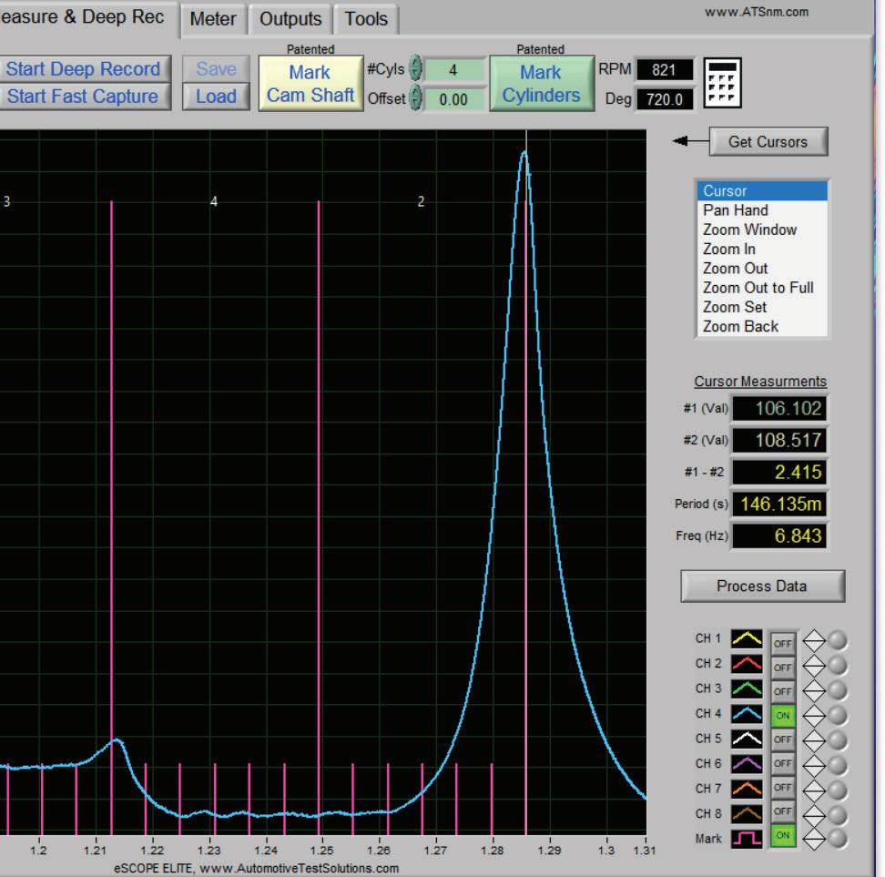
Fig. 8
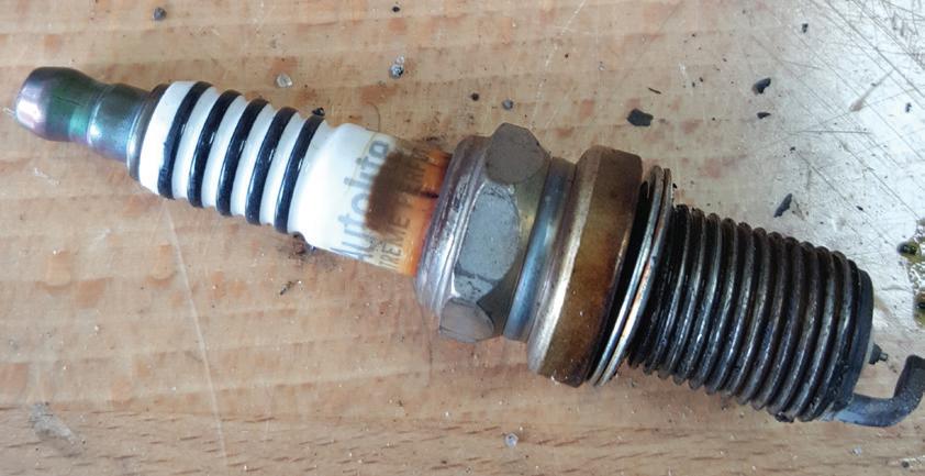
Fig. 9
One thing that’s important before you replace the computer is to make sure that you’re getting all the proper powers and grounds to the unit. If you’re missing one ignition power feed to the computer and you replace that computer, then you’re going to have the exact same issue. That can be a pretty expensive mistake. The important thing I want to convey here is when an engine is misfi ring, you want to keep your testing as basic and precise as you can. By isolating each choice and focusing on them one at a time, you are eliminating possible culprits one at a time. If I go through all of my
Fig. 8: Hook up an amp clamp to the power feed of the fuel pump and turn on the pump. Using the lab scope, study the bumps in the waveform for consistency.
Fig. 9: Example of a spark plug with carbon tracking. This can indicate a cracked insulator. testing on one of the choices and everything tests positive, then I know that the system I tested is not creating my misfi re. Then I can go to the next system and eliminate that one. Eventually, you’re going to pinpoint the problem through the process of elimination.
Like I said earlier, it doesn’t matter what system you start your testing with. As you become more seasoned, then you can use your gut feeling and start with the system that you think is causing the problem.
With the proper training and by using the proper tools and developing your diagnostic game plan, you will be able to nail down a misfi ring vehicle quickly and effi ciently. As a wise man once said, “Experience is the best teacher.” Misfi ring vehicles will always be there for technicians to become increasingly skilled.
Edwin Hazzard owns South East Mobile Tech in Charleston, S.C., which is a mobile diagnostic and programming service providing technical service to many automotive and body repair shops. He has 38 years of experience in the automotive industry. He currently is an automotive trainer, a board member of TST (Technician Service Training), a member of the MDG (Mobile Diagnostic Group), a member of the Professional Tool and Equipment advisory board for Pten magazine, a committee member of Nastaf and is a beta tester for multiple tool makers.