

User Manual


1 STELLARTM KNEE GENERAL INFORMATION
1.1 Indications for Use
STELLAR Knee is a stereotaxic system including an intraoperative software as a medical device and surgical instruments. STELLAR Knee is indicated for primary Total Knee Replacement, to assist the surgeon in determining reference alignment axes in relation to anatomia Head Mounted Device (HMD) for displaying information to the user intraoperatively. The HMD should not be relied upon solely and should always be used in conjunction with traditional methods.
1.2 Intended Use
PolarisAR STELLAR Knee System is a non-invasive software system intended to provide intraoperative planning and intraoperative data for total knee arthroplasty.
STELLAR Knee is intended for use in operating rooms within hospitals, private clinics, outpatient surgical centers and other clinical environments. It should be used in a closed space with sufficient lighting. A full set of manual instruments should be available to permit the completion of manual implantation of implants in case STELLAR Knee cannot be used to complete the case.
1.3 Contraindications
• Patients for whom a hip center of rotation cannot be established using the STELLAR Knee landmarking protocols
• Patients in whom the necessary bony landmarks needed for registration are not present or accessible
• Patients with insufficient bone density to support the array pins should not be treated using the STELLAR Knee
• Active infections of the knee joint area
• Knee replacement revision surgery
• Presence of strong infrared sources or infrared reflectors in the vicinity of the STELLAR Knee marker spheres
• Contraindications for the implant as given by the implant manufacturer
1.4 Training
Prior to using the system, surgeons should follow training given by a PolarisAR representative or the distributor for the given applications. Contact your local PolarisAR representative.
Warning: The system should only be used by trained surgeons.
1.5 Implant Use
The prosthesis implanted with the system must be used in accordance with the appropriate package insert labeling. The procedure is to be performed in accordance with the corresponding surgical technique published by the manufacturer for the specific implant.
Warning: The system should only be used with the instruments provided by PolarisAR or by the distributor for the given application.
1.6 Copyright and Trademark
© PolarisAR 2024. All rights reserved. PolarisAR™ and STELLARTM are trademarks of PolarisAR
1.7 Product Label Symbols
Single-Patient, Single-Procedure
Device. Do Not Re-use Caution, Consult Accompanying
Documentation
Consult Instructions for Use
Caution: Federal (USA) law restricts this device to sale by or on the order of a physician
Serial Number
Batch Code

1.8 Available Documentation
Manufacturer Catalogue
Number Do Not Use if Package Damaged
Fragile, Handle With Care
PolarisAR STELLARTM Knee System User Manual
Sterilized Using Ethyl Oxide
Non-Sterile
Upper Limit of Temperature
Unique Device Identifier UDI
Use-by-Date
Do Not Resterilize
Read all documentation carefully. Refer to these documents when operating STELLAR Knee. Figures are representative. It is important to review these documents thoroughly before operating STELLAR Knee. Additional information, training, and product servicing are available from PolarisAR. When using additional items not provided by PolarisAR , please refer to the appropriate Instructions for Use (IFUs).
STELLAR Knee Documentation
STELLAR Knee User Guide
System Installation
• Instructions for Use of the STELLAR Knee
• Comprehensive information on system functions and components • Overview of treatment planning and image-less navigation
• Guidelines for the preparation of the anatomy for compatible primary knee systems using STELLAR Knee
DO NOT use the STELLAR Knee prior to a proper installation and system check by authorized PolarisAR personnel. Only authorized PolarisAR personnel should assemble, install, maintain and service the STELLAR Knee application. Contact your PolarisAR STELLAR representative.
2 SYSTEM OVERVIEW
This section outlines the key functions of the PolarisAR STELLAR Knee System
The system follows a predefined surgical workflow that includes the following steps:
1. System setup
2. Array attachment
3. Registration of the bony landmarks
4. Initial leg alignment and gap assessment
5. Gap balancing
6. Final alignment and gap assessment
7. Planned resection depths and guided resections
2.1 Method of Operation
The PolarisAR STELLARTM Knee Application is an augmented reality assisted surgical navigation system. It uses established surgical navigation techniques with the HoloLens 2 and system arrays to track patient bony landmarks in real time. PolarisAR STELLAR Knee guides the surgeon through the capture of bony landmarks to visualize data to assist the surgeon in determining resection angles and measurements.
2.2 Key Features
• Hologram Overlay
• Array Detection
• Procedure Planning
• Cut Guides
The PolarisAR STELLAR Knee Application is an augmented reality assisted surgical navigation application to assist the surgeon in the following:
Assessing patient anatomy - The assessment is performed intraoperatively without the need for preoperative x-rays or scans. The surgeon captures bony landmarks on the patient anatomy through the use of a femoral array, a tibial array, a stylus array and the HoloLens 2.
Limb alignment, range of motion, and laxity are evaluated in real time.
The surgical plan is determined intraoperatively according to the surgeon’s selected preferences.
The surgeon maintains full control of the surgical plan.
2.3 Main Components
The main components of the PolarisAR STELLAR Knee System consist of the following:
• HoloLens 2
• Femoral Array
• Tibial Array
• Stylus
• Fin Array
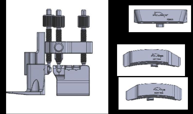
• Resection Guides

2.4 Functional Use
The main function of the STELLAR Knee is to assist the surgeon in determining the position and orientation of anatomical structures, plan the position of the femoral and tibial implant components intraoperatively, and prepare the bones during total knee arthroplasty.
2.5 Software Interface Overview
This section outlines the key functions of the STELLAR Knee Application. The system follows a predefined workflow consisting of the following:
• Preferences
• Setup
• Landmarking
• Assessment
• Balancing
• Resections
• Exit
As well as:
• Warnings
• Voice Command and hand Gesture Reference
Application for STELLAR Knee Flowchart Screen Overview
WARNING: The STELLAR Knee requires a fully charged HoloLens 2 before each surgical use. Fully charging the HoloLens 2 requires approximately 65 minutes as determined by Microsoft.
Application Launch
Turn on headset
Login credentials/iris login
Splash Screen
Splash screen launches to confirm that app is running. Splash screen displays labeling and version number.

Preferences Setup
Select femoral tibial resection order
Femoral axes preferences
Angle preferences

Landmarking
This screen guides the surgeon through the landmarking process
QR calibration scanning, array detection & selected knee
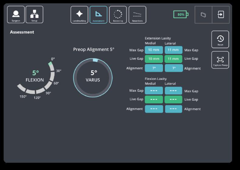
Assessment
Allows the surgeon to assess and capture patient ligament laxity data while displaying correlating extension/flexion and varus/valgus angles and medial and lateral extension/flexion gap metrics

Balancing
the


The

and actual

Sub Menu
The sub menu allows access to the buttons below Exit Confirmation
The exit confirmation allows the surgeon to confirm exiting the application

3 TECHNICAL CHARACTERISTICS
3.1 System Specifications
The system is composed of:
• HoloLens 2, loaded with STELLAR Knee application.

HoloLens2https://support.microsoft.com/en-us/topic/product-safety-warnings-and-instructions-726eab87-f471-4ad8-48e5-9c25f68927ba
• Instruments
- Universal Resection Guide
- Distal Femoral Resection Block
- Proximal Tibial Resection Blocks
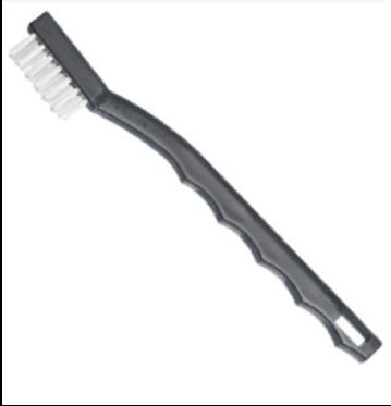
- Hand Driver
- Hudson Adapter
- 6mm Headed Pin
• Disposable Instruments
- Femoral Array
- Tibial Array
- Stylus
- Fin Array
- Pins
Manual instrumentation should always be available in the event the surgeon cannot continue with the PolarisAR STELLAR Knee System.
The procedure requires the following additional items not provided by PolarisAR: Implants, 4-in-1 resection guides, drills, saws
Only use instruments provided by PolarisAR . Using unauthorized instruments may adversely affect safety and/or effectiveness of the system. Using equipment not specified in this manual with the system may result in malfunctions and patient/user injury.
3.2 Operating Environment
Operating Environment - STELLARTM Knee is intended for use in operating rooms within hospitals, private clinics, outpatient surgical centers and other clinical environments.
4 WARNINGS AND CAUTIONS
4.1 Warnings
Warning: Shorter headed pins should be used to secure the Universal Resection Guide to the bone through the feet. If longer pins are needed, care should be taken to not protrude through the posterior cortex of the bone.
Warning: STELLAR Knee should not be used for procedures expected to last longer than the HoloLens 2 battery life. Please see the HoloLens 2 documentation for more information.
https://docs.microsoft.com/en-us/hololens/hololens2-charging#charging-the-device
Warning: The STELLAR Knee requires a fully charged HoloLens 2 before each surgical use. Fully charging the HoloLens 2 requires approximately 65 minutes as determined by Microsoft.
Warning: Manual instrumentation should always be available in the event the surgeon cannot continue with the PolarisAR STELLAR Knee System.
Warning: Using unauthorized instruments may adversely affect safety and/or effectiveness of the system. Using equipment not specified in this manual with the system may result in malfunctions and patient/user injury.
Warning: Careful acquisition of landmarks is essential for the system to plan and execute accurately. The landmarks acquired should be representative. Small anatomical defects or protruding osteophytes that are not representative should not be acquired, as they may falsely represent the landmark needed.
Warning: Do not puncture cartilage with the pointer.
Warning: Do not apply excessive force to stylus during landmark collection.
Warning: The arrays must remain visible to the HoloLens camera during the landmarking steps.
Warning: Do not use in situations where contraindications could interfere with the landmark collection.
Warning: Only use the Fin in resection slots that meet PolarisAR standard size requirements.
Warning: Check guide position before making resections.
Warning: Check guide position resection screen after pinning guide but before cutting.
Warning: Validation only allows to confirm cut.
Warning: Do not drop headed pins in patient. Do not injure patient when retrieving any dropped headed pins. Count headed pins.
Warning: Refer to instructions to properly attach the fin tool to the 4:1 femoral resection guide.
Warning: The length and positioning of the array headed pins should not interfere with the surgical instruments including the saw and retractors.
Warning: Ensure bone arrays are optimally placed and rigidly fixed to bone.
Warning: Follow the provided instructions for cleaning and sterilization of the reusable instruments.
Warning: Validate the applicable resection to confirm actual resection matches planned resection.
4.2 Cautions
Caution: Clean headset prior to procedure.
Caution: Clean HMD lens before each procedure.
Caution: The HMD is not sterile.
Caution: Each HMD is intended for a single user. No shared accounts are permitted. Do not share passwords.
Caution: If the HMD does not detect the surgeon’s iris, a PIN will need to be entered.
Caution: If performing more than one procedure, more than one HMD should be available.
Caution: Ensure all STELLAR Knee components are accounted for and functioning properly prior to surgery. This includes the HMD, Reusable Instrumentation, and STELLAR Knee Disposable Kit.
Caution: Accept all device capability prompts (camera, eye tracking, microphone).
Caution: One STELLAR Knee Kit will be scanned and used per surgical procedure.
Caution: Care should be taken to not cause damage to arrays when handling.
Caution: Check for the array tracking indication on the fiducials.
Caution: Care should be taken to not cause damage to resection guides and blocks when handling.
Caution: Properly handle and dispose of this product in accordance with accepted medical practice and with applicable local, state and national laws and regulations.
Caution: Properly dispose of the lithium battery by returning the HMD to PolarisAR .
Caution: Follow best practices for hand tracking.
Caution: A full set of the implant system’s standard instrumentation is needed to perform a surgery in conjunction with the STELLAR Knee and in case the STELLAR Knee software cannot be used.
Caution: Markers should be kept clean of debris and fluids by gently wiping the fiducial with a clean cloth.
Caution: Do not over seat the entry headed pin.
Caution: The bone arrays are intended for one time use.
Caution: User must exit and scan a new kit to begin another surgical procedure.
Caution: Sterilized reusable instruments should be stored in a dry, clean environment, protected from direct sunlight, pests, and extremes of temperature and/or humidity.
Caution: Do not exit STELLAR Knee application until procedure is complete.
Caution: No user serviceable parts. Contact PolarisAR with any questions.
Caution: Please see the HoloLens 2 documentation for additional information regarding the HoloLens 2 device: https://support.microsoft.com/en-us/topic/product-safety-warnings-and-instructions-726eab87-f471-4ad8-48e5-9c25f68927ba
5 HEADSET
5.1 Headset Description
HoloLens 2 is an ergonomic, untethered self-contained holographic device with enterprise-ready applications to increase user accuracy and output. PolarisAR is harnessing the power of HoloLens 2 to achieve new ways of navigating in TKA surgery.
Caution: Please see the HoloLens 2 documentation for additional information regarding the HoloLens 2 device: HoloLens 2
https://support.microsoft.com/en-us/topic/product-safety-warnings-and-instructions7 26eab87-f471-4ad8-48e5-9c25f68927ba

5.2 Surgical Procedure Use
To set up your HoloLens 2 for first-time use, please refer to the following: https://docs.microsoft.com/en-us/hololens/hololens2-setup
It is recommended that you spend time in your HoloLens 2 to become familiar with the interactions before using in surgery for the first time.
5.3 Cleaning
Please refer to section 11.2 for detailed information on cleaning your HoloLens 2.
Caution: Clean headset prior to procedure.
Caution: Clean HMD lens before each procedure.
Caution: The HMD is not sterile.
5.4 Transport and Storage:
HoloLens 2 should be transported and stored in its provided case.
5.5 Charging
Warning: The HoloLens 2 should be fully charged before each procedure. Full details on charging your HoloLens 2 can be found here: https://docs.microsoft.com/en-us/hololens/hololens2-charging#charging-the-device
5.6 Battery Usage
2–3 hours of active use
More information on the HoloLens 2 battery life can be found here: https://docs.microsoft.com/en-us/hololens/hololens2-charging
5.7 Instrumentation
Part Number Part Name
80-0001 Kit, Total Knee, Left
80-0002 Kit, Total Knee, Right
50-0001/ 50-0018 Femoral Array, Left/Right
50-0002/ 50-0019 Tibial Array, Left/Right
50-0003 Stylus
50-0004 Fin
30-0023 Headed Pin, 3.5mm x 33mm
30-0025 Headed Pin, 3.5mm x 50mm
40-0021 Fluted 3.2mm Straight Pin
Part Number Part Name
80-0003 Reusable Instrumentation
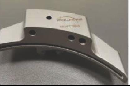
50-0005 Universal Resection Guide
30-0016
30-0017
30-0020
Femoral Resection Block
Tibial Resection Block, Left
Tibial Resection Block, Right
30-0021 Hudson Adapter
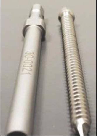
30-0022 Pin Driver
30-0026 Headed Pin, 6mm x 80mm
30-0027 Sterilization Tray
The system should only be used with the instruments provided by PolarisAR or by the OEM for the chosen knee implant for the given application.
Warning: Using unauthorized instruments may adversely affect safety and/or effectiveness of the system. Using equipment not specified in this manual with the system may result in malfunctions and patient/user injury.
Warning: Manual instrumentation should always be available in the event the surgeon cannot continue with the PolarisAR STELLAR Knee System.
Caution: If performing more than one procedure, more than one HMD should be available.
Caution: Care should be taken to not cause damage to arrays when handling.
Caution: Care should be taken to not cause damage to resection guides and blocks when handling.
5.8 Single Use Sterile Instruments
The bone arrays are intended for one-time use. They are shipped in sterile packaging. Each array is unique and requires linking to the system by scanning the QR code on each respective package. The array is ready to be attached after it is recognized by the system. Please see troubleshooting for problems with scanning the arrays for use.
If scanning new QR code for new set of markers, remove any other markers from view of the HoloLens.
Caution: Properly handle and dispose this product in accordance with accepted medical practice and with applicable local, state and national laws and regulations.


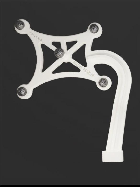
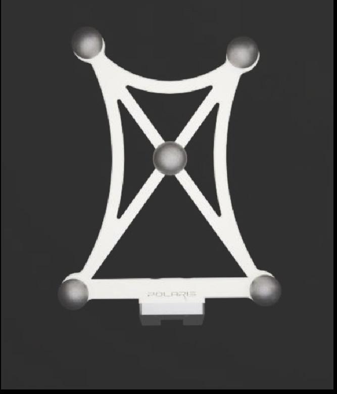
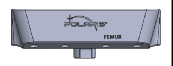
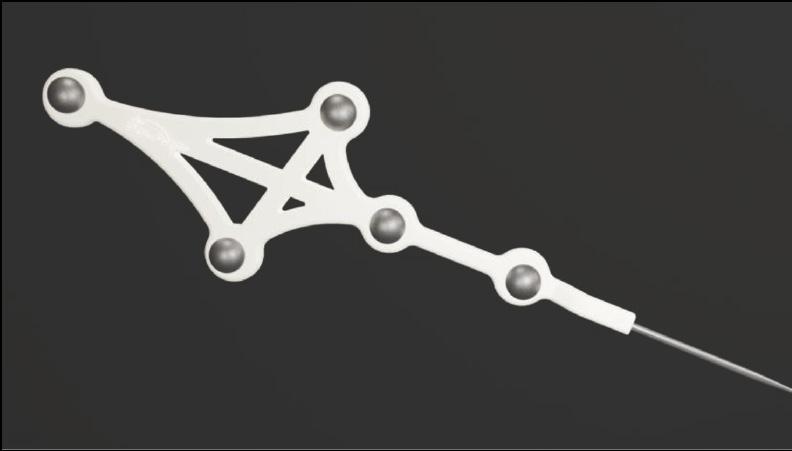
5.8.2 Femoral and Tibial Bone Arrays
Bone arrays are fixed to the bones via the array headed pins.
• Femoral Array
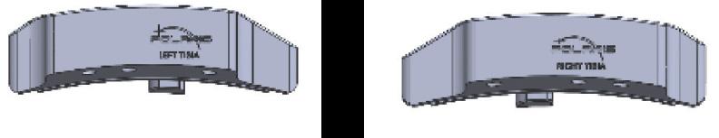
• Tibial Array

5.8.3 Fin
Fin is used to track the resection guides.
5.9 Reusable Instrumentation
Caution: Sterilized reusable instruments should be stored in a dry, clean environment, protected from direct sunlight, pests, and extremes of temperature and/or humidity.
5.9.1 Universal Resection Guide
The Universal Resection Guide is used in performing resections of both left and right knees and both femur and tibia.
5.9.2 Femoral Resection Block
Resection block is designed to assist in the femoral resection.
5.9.3 Tibial Resection Blocks
Resection blocks are designed to assist in the tibial resections. Tibial resection blocks are side specific.

6 APPLICATION USER INTERFACE
STELLAR Knee uses a combination of user interface screens in augmented reality that allows the surgeon to interact with the screen with hand gestures. The surgeon can also use voice interaction that allows the surgeon to control the interface with voice commands. Specific hand gestures and voice commands can be found in the HoloLens 2 user manual.
6.1 Graphical User Interface
Splash Screen

6.2 Navigation Menu and Sub Menus
The Splash Screen with the PolarisAR logo and branding appears on launch of the application. The splash screen fades and the UI Setup screen appears.
All buttons can be pressed by touching with the index finger.
The main navigation menu is pictured below.
The main navigation menu consists of the following buttons:
1. Surgeon – Selects the Surgeon Preferences screen
2. Setup – Selects the Setup screen
3. Landmarking – Selects the Landmarking screen
4. Assessment – Selects the Assessment screen
5. Balancing – Selects the Balancing screen
6. Resections – Selects the Resections screen
7. Follow Me – Toggles to make the panel follow the user.
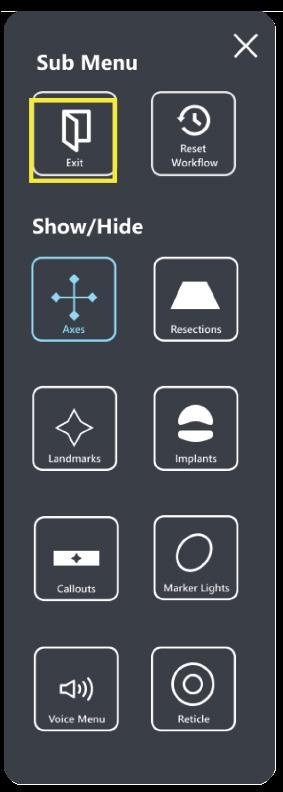
6.2.1 Sub Menu
The Sub Menu is selected by touching the “Drawer” button (highlighted yellow) which opens the Sub Menu as an extension of the main UI panel. The Sub Menu is pictured below.

The Sub Menu consists of the following:
1. Exit button
2. Reset Workflow button
3. Show and Hide Axes button
4. Show and Hide Resections button
5. Show and Hide Landmarks button
6. Show and Hide Implants button
7. Show and Hide Callouts button
8. Show and Hide Voice Menu button
9. Show and Hide Reticle button

6.2.2 User Interface Screens
User Interface consists of the following screens:
• Preferences
• Setup
• Landmarking
• Assessment
• Balancing
• Resections
• Submenu
• Voice Command Reference


All landmark text turns green when all landmarks are captured. Touch any landmark name to reset the landmark.
6.2.6 Assessment Screen
6.2.7 Balancing Screen


6.2.8 Resection Screens

6.3 Voice Interface
PolarisAR STELLAR Knee uses voice commands with the HoloLens 2 to complete certain interactions. Voice commands consist of the following:
• Show Panel
• Show Axes
• Show Implants
• Show Resections
• Show Callouts
• Show Landmarks
• Show Markers
• Show Submenu
• Show Reticle
• What can I say?
• Reset Femur
• Reset Landmarks
• Follow Me
• Hide Panel
• Hide Axes
• Hide Implants
• Hide Resections
• Hide Callouts
• Hide Landmarks
• Hide Markers
• Hide Submenu
• Hide Voice Menu
• Hide Reticle
• Reset Tibia
• Capture Pre-op
• Balancing
• Assessment
• Landmarking
• Resections
• Setup
• Surgeon
• Reset
• Reset Workflow
• Show Voice Menu
• Eye Calibration
• Cancel
• Go Back
• Extension
• Flexion
• Femoral
• Tibial
• Four in One
The surgeon can use these voice commands instead of hand interactions to interact with the interface. Each voice command has a related button for hand interaction in the event that the voice commands are not heard.
6.4 Hand Interactions
Near Interaction Touch - STELLARTM Knee uses hand interactions to interact with the augmented reality interface. The interface allows the surgeon to touch and press buttons on the AR UI panels.
To interact with the UI panels, bring your hand close to the buttons. A white ring should appear at the tip of your index finger. This “touch cursor” allows you to interact with the buttons on the screen. Touch and push the button as you would any button in the real world to select the button. Scroll content when applicable by swiping on the surface of the panel with your finger as if using a touch screen.
Grab – The UI panel can be grabbed and moved to the surgeon’s ideal location.
To grab the UI panel near you, pinch your thumb and index finger together on the UI panel and hold. To let go, release your fingers. Use this grab gesture to move the UI panel.
6.5 Anatomical AR Displays
Angles, guides, axes, implants, and metrics are displayed on the patient anatomy for enhanced viewing. Displays change in real time depending on the current position of the patient anatomy.
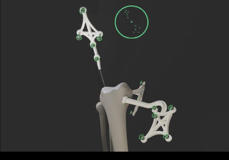
Array state is indicated by green circles on the fiducials when the arrays are active.
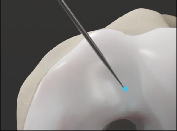
Landmarks appear as a blue landmark object on the patient anatomy. Landmarks change to green when confirmed.
Optional anatomical AR displays can be hidden in two ways:
Voice Commands:
• Show Axes
• Show Resections
• Show Implants
• Show Callouts
• Show Landmarks
• Show Markers
• Show Reticle
• Hide Axes
• Hide Resections
• Hide Implants
• Hide Callouts
• Hide Landmarks
• Hide Markers
• Hide Reticle
6.6 Navigation
Buttons on the Sub Menu
• Show/Hide Resections
• Show/Hide Axes
• Show/Hide Implants
• Show/Hide Callouts
• Show/Hide Landmarks
• Show/Hide Markers
• Show/Hide Reticle
The surgeon navigates the STELLAR Knee application using the UI screen in augmented reality as well as the arrays on the anatomy and via array attachment on the resection guide. Resection guides, axes, and holographic implants are placed in augmented reality to assist the surgeon with surgical navigation.
7 SURGEON ACCOUNT
Caution: Each HMD is intended for a single user. No shared accounts are permitted. Do not share passwords.
Set up surgeon account with PolarisAR
The surgeon will be provided with a unique password to use when logging in to the HoloLens 2 HMD.
Enter all required information:
– First and last name – E-mail address
– Password – Confirm password
8 SYSTEM SETUP
8.1 System Setup Summary
1. Fully charge HoloLens 2
2. Put on HoloLens 2 and turn on
3. STELLAR Knee application launches automatically and opens to Setup screen
4. Set preferences (first time)
5. Scan QR image on array packages
6. Attach arrays
Caution: The PolarisAR STELLAR Knee application requires a fully charged HoloLens 2. Fully charge HoloLens 2 prior to use according to https://docs.microsoft.com/en-us/hololens/hololens2-charging#charging-the-device
8.2 First Time Setup
Caution: Accept all device capability prompts (camera, eye tracking, microphone).
Please see the following for initial setup of the HoloLens 2. https://docs.microsoft.com/en-us/hololens/hololens2-setup
8.3 Return Sessions
Fully charge HoloLens 2 prior to use.
Turn on HoloLens 2.
The STELLAR Knee application will launch automatically when the user is logged in.
9 INTRAOPERATIVE USE
9.1 Presurgical Checklist
1. Fully charged HoloLens 2
2. STELLAR Knee Disposable Instrumentation Kit (right or left)
3. STELLAR Knee Reusable Instrumentation
4. Knee Implant System Instrumentation
Caution: Ensure all STELLAR Knee components are accounted for and functioning properly prior to surgery. This includes the HMD, Reusable Instrumentation, and STELLAR Knee Disposable Kit.
Ensure that one STELLAR Knee Kit will be scanned and used per surgical procedure. User must exit and scan a new kit to begin another surgical procedure.
The headset should remain in the headset carrying case during transportation and storage.
Warning: A full set of the implant system’s standard instrumentation is needed to perform a surgery in conjunction with the STELLAR Knee and in case the STELLAR Knee software cannot be used. Effects that may prevent use of the STELLAR Knee system include the unlikely possibility of unresolvable interference affecting the communication of the system.
9.2 Powering On and System Setup
Outside of the sterile zone and before scrubbing in, place the headset on the surgeon’s head. Press the power button (black button) located behind the right ear of the surgeon, in the back of the headset, to turn on the headset.
Caution: If the headset does not detect the surgeon’s iris, a PIN will need to be entered.
1. The PolarisAR STELLAR Knee Splash screen is displayed after boot-up is completed.
2. Check headset battery display.
3. Scrub in per normal surgeon protocol.
Caution: The headset is not sterile.
The HoloLens 2 requires 65 minutes to fully charge according to Microsoft documentation. STELLAR Knee cannot be used without a fully charged HoloLens 2.
To turn on
To sleep
To wake from sleep
To turn off
To force the HoloLens to restart if it is unresponsive
Single button press. All five lights turn on, then change to indicate the battery level. After four seconds, a sound plays.
Single button press. All five lights turn on, then fade off one at a time. After the lights turn off, a sound plays and the screen displays “Goodbye.”
Single button press. All five lights turn on, then change to indicate the battery level. A sound immediately plays.
Press and hold for 5s. All five lights turn on, then fade off one at a time. After the lights turn off, a sound plays and the screen displays “Goodbye.”
Press and hold for 10s. All five lights turn on, then fade off one at a time.
Check that the HoloLens 2 is fully charged and that all five lights turn on.
Preoperative Setup Checklist:
1. Fully charged HoloLens 2
2. Femoral Array in sterile package
3. Tibial Array in sterile package
4. Fin Array in sterile package
5. Stylus in sterile package
6. Resection guides sterilized by user facility
9.3 STELLARTM Knee Application Launch
The STELLAR Knee application will launch automatically when the user is logged in.
9.4 Surgeon Preferences and Setup Modes
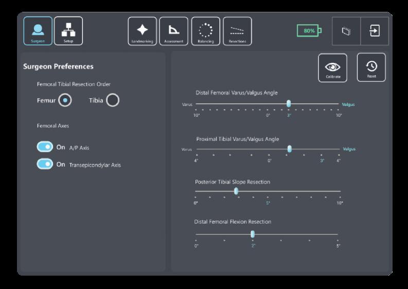
9.4.1 Surgeon Preferences Mode
Surgeon preferences is a one-time process on the Surgeon Preferences Screen. Preferences persist for all following procedures. The surgeon can return to this screen at any time to change preferences. Note: Changing preferences will override any manual changes from previous balancing.
Preferences include the following:
1. Select preferred first resection
2. Set optional anteroposterior (A/P) and transepicondylar (TE) axes
3. Set starting varus/flexion angles for tibia and femur:
• Distal femoral varus/valgus angle
• Proximal tibial varus/valgus angle
• Posterior tibial slope resection angle
• Distal femoral flexion resection angle
To move the slider, grab the slider button with the thumb and forefinger.
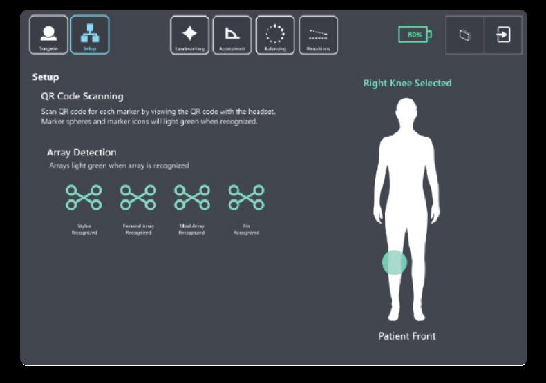
9.4.2 Setup Mode
In Setup Mode, the surgeon can activate the pending surgery by scanning the QR code associated with a Right or Left STELLAR Knee Kit. This action will select the proper side for surgery and calibrate the arrays prior to femoral and tibial array placement.
Caution: One STELLAR Knee Kit will be scanned and used per surgical procedure.
9.4.3 Intra-Operative Array Calibration
1. Select the appropriate STELLAR Knee Kit for right or left knee.
2. Open STELLAR Knee Kit.
3. Locate the QR Code on STELLAR Knee Disposable Kit packaging label.
4. Using the Headset, on Setup Screen, simply look at and scan the QR calibration image.
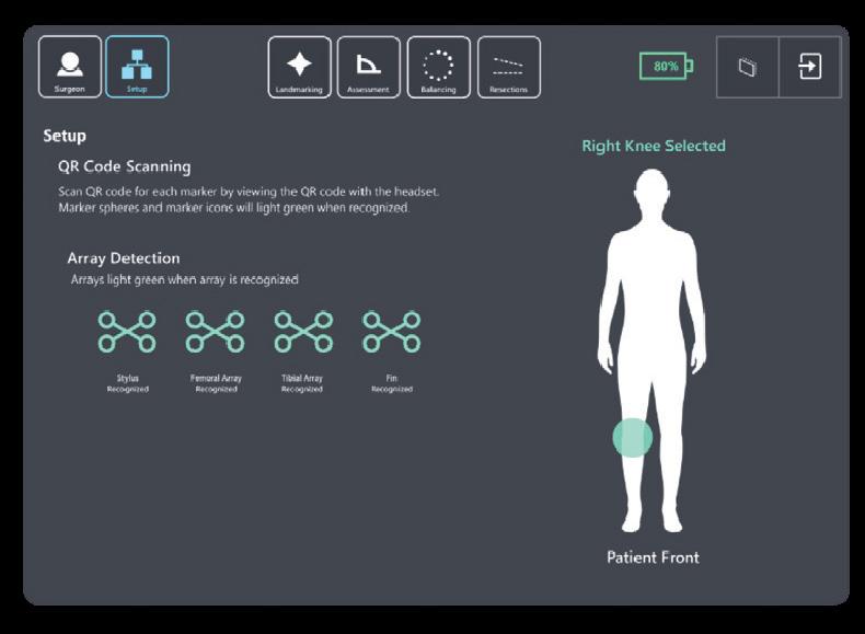
5. Once the Headset reads the QR image, the user will see a GREEN square overlayed on the QR calibration image.
6. The user should now simply look at the items in the kit. The arrays will illuminate with a GREEN CIRCLE and the four arrays (Stylus, Fin, Femoral, and Tibial) seen in Setup will move from RED to GREEN.
Caution: Check for the array tracking indication on the fiducials.
After scanning the QR images, the user is now ready to place the arrays on the femur and tibia. After QR calibration scanning, the arrays will function for the duration of the surgery.
If scanning a new QR image for a new marker set, be sure only the markers associated with the new QR image are in view of the HoloLens.
Caution: Care should be taken to not cause damage to arrays when handling.
Patient Side Selection is recognized by the QR calibration scanning.
The patient selected knee will be displayed on the Setup screen.
The surgeon cannot proceed to the Landmarking screen until the Stylus, Fin, Femoral Array, and Tibial Array have been recognized by the system. The system will prompt a notice that the arrays have not been identified.
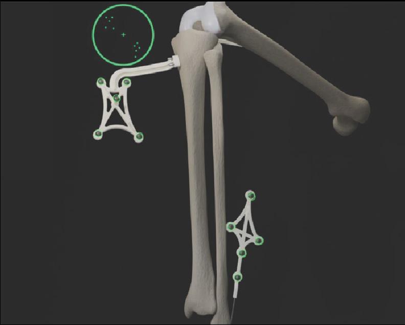
9.5 Femoral and Tibial Array Placement


The Femoral and Tibial Arrays are the fixed reference points used to create an accurate frame of reference for the system. The headset camera tracks the orientation of these arrays throughout the procedure. This is how the system communicates with the knee anatomy. The arrays are pre-calibrated and provided sterile. A set of headed pins is included in the sterile STELLAR Knee Kit.
Warning: Do not drop headed pins in patient. Do not injure patient when retrieving any dropped headed pins. Count headed pins.


These pins are used to fix the arrays to the femur and tibia at the beginning of surgery. Array headed pins should be positioned in the bone such that:
• Array line of sight with the headset camera can be maintained.
• Saw access to the knee is not compromised.
The length and positioning of the array headed pins should avoid:
• Conflict with the surgical instruments including the saw and retractors.
• Bone resections: Distal Femoral Condyles, Posterior Femoral Condyles, box for a PS implant, or Tibial Keel. Page 22 of 40
• Stresses from adjacent soft tissues during knee flexion and extension.
Remove the Femoral and Tibial Arrays from the array pouches inside the STELLARTM Knee Kit. Place them on the sterile instrument table using sterile technique.
Arrays are labeled:
• right femur
• right tibia
• left femur
• left tibia


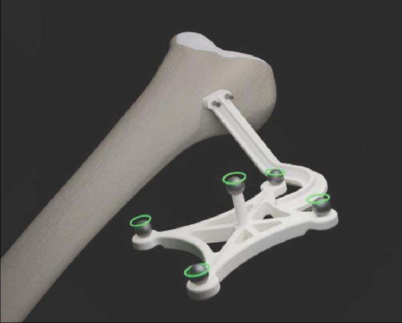
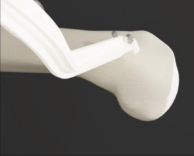
9.5.1 Femoral Array Placement
1. With the knee visible and inside the incision, with respect to the medial epicondyle, the array headed pins are inserted proximally and anteriorly, angling laterally toward the mechanical axis of the femur.
2. Drill the first array headed pin closest to the joint line. Do not fully seat the pin.
3. Using the pin hole closest to the joint line, drill a second array headed pin through the hole furthest from the joint line. Do not fully seat the pin.
4. Ensure array is properly fixed and positioned to bone and complete final seating with pin driver.
5. Care should be taken to avoid overpenetration.

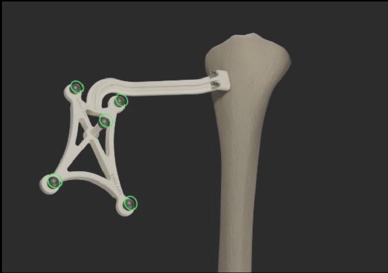
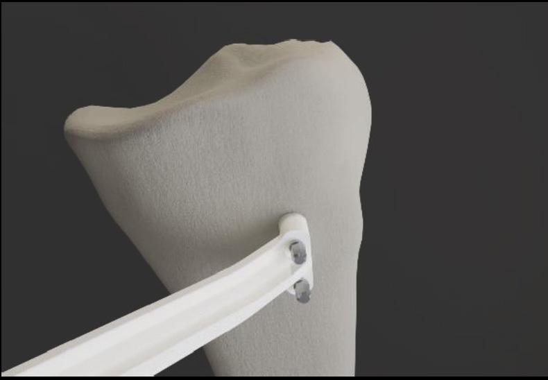
9.5.2 Tibial Array Placement
1. With the knee visible and inside the incision, the array headed pins are inserted adjacent to the medial aspect of the tibial tubercle. The pin box should be aligned with the tibial axis.
2. Drill first array headed pin furthest from the joint line. Do not fully seat the pin.
3. Using the pin hole furthest from the joint line, drill second array headed pin through the hole closest to the joint line. Do not fully seat the pin.
4. Ensure array is properly fixed and positioned to bone and complete final seating with pin driver.
5. Care should be taken to avoid overpenetration.

9.5.3 Array Attachment Reference
Warning: The length and positioning of the array headed pins should not interfere with the surgical instruments including the saw and retractors.
Warning: Ensure bone arrays are optimally placed and rigidly fixed to bone.
Movement of the arrays or loosening of the array headed pins will compromise the accuracy of the system. Adjustments to the position of the bone arrays can only be made prior to landmarking.
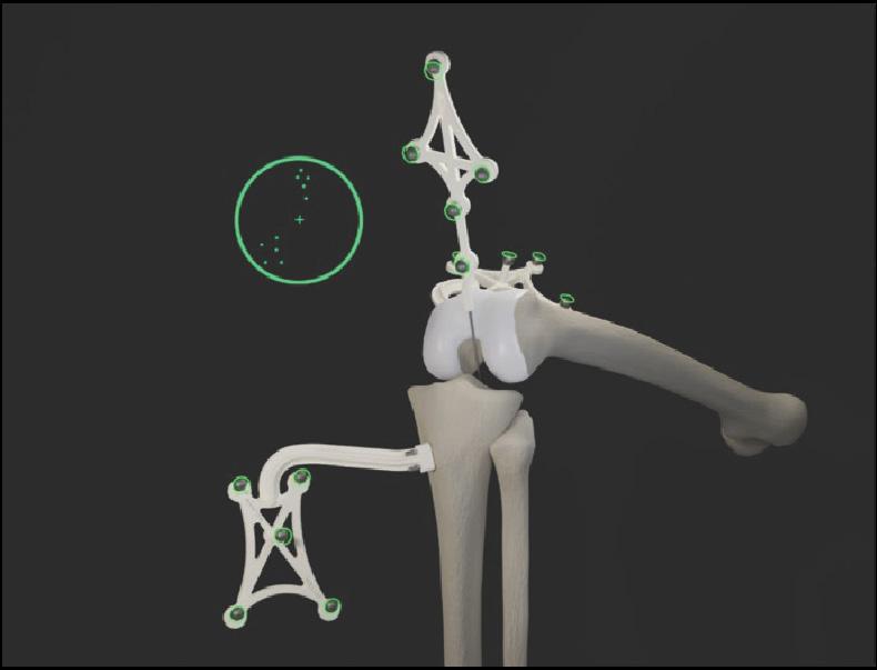
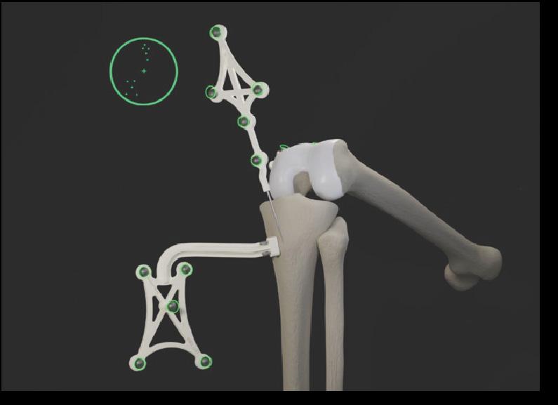
Adjustments to landmarks are permitted after the initial landmarks have been captured. The user may go back and repeat any landmark they would like. They may also “reset” landmarking to capture all landmarks and restart the procedure by touching the “reset” button on the landmarking screen or using the “reset” voice command. Femoral landmarks may be reset using the “reset femur” button or the “reset femur” voice command. Tibial landmarks can be reset using the “reset tibia” button or using the “reset tibia” voice command.
Bone arrays are visible (GREEN CIRCLE) to the headset camera when they become illuminated with a GREEN CIRCLE. The surgeon should have visibility at all leg positions during the procedure. This is achieved simply by using the headset to look at the arrays.
Arrays equipped with reflective spheres must have an unobstructed line of sight path to the headset camera to be tracked. To minimize interference with the headset camera, keep bright light sources (certain OR lights, direct sunlight) or highly reflective objects out of the headset camera’s field of view.
9.6 STELLARTM Knee Modes of Operation
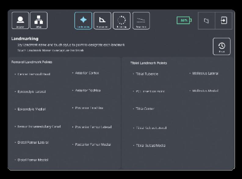
9.6.1 Landmarking Mode
To initiate Landmarking Mode, the surgeon can select the “Landmark” icon from the menu using hand gesture or say “Landmark” from the menu.

Warning: Do not use in situations where contraindications could interfere with the landmark collection.
Caution: Follow best practices for hand tracking.
Warning: Careful acquisition of landmarks is essential for the system to plan and execute accurately. The landmarks acquired should be representative. Small anatomical defects or protruding osteophytes that are not representative should not be acquired, as they may falsely represent the landmark needed.
Warning: Do not apply excessive force to stylus during landmark collection.
The STELLAR Knee Stylus will be used to acquire the location of the landmark on each bone.
The goal of the landmarking process is to acquire the anatomical landmarks and axes which will be used by the system for surgical planning and balancing.
All Acquisition Steps
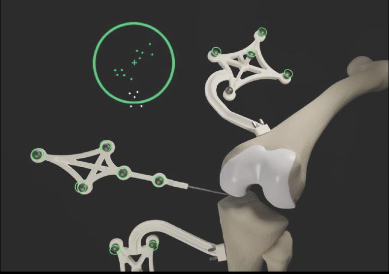
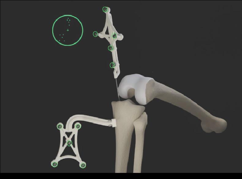
When capturing Femoral Landmarks, the femoral marker and the stylus should be visible to the headset with the central area of the reticle. Do not block visibility of the marker with hands when capturing landmarks.
Refer to the associated images for each landmark for proper viewing angle when capturing landmarks. Landmark “pairs” should be captured from similar viewpoints.
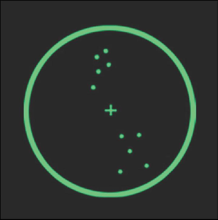
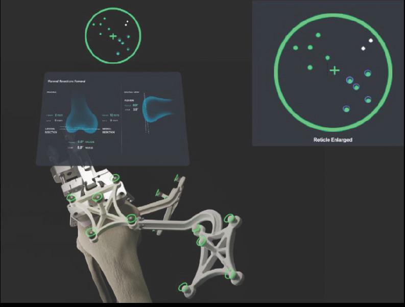
The Reticle During Landmarking
The reticle is designed to provide alignment guidance for the best capture position for each landmark. The stylus and the femoral array
or tibial array should be positioned in the central area of the reticle for the best headset position for each landmark. The femoral array for femoral landmarks and tibial array for tibial landmarks should be green in the reticle for landmark capture.
Landmark capture is confirmed in the following ways:
1. Landmark appears blue when recognized.
2. Landmark visually changes from blue to green on the patient anatomy and on the landmark UI Screen when confirmed.
3. Audio notification tone.
4. The system proceeds to the next landmark.
When a landmark has been successfully acquired, an audible notification will sound, and the landmark will illuminate on the bone with a green “diamond.” The software will automatically proceed to the next landmark.
Resetting and recapturing landmarks
Landmarks can be recaptured at any time. To recapture a landmark, select the specific landmark and recapture the point on the anatomy with the stylus. The previous point is not discarded by the system until the new point is collected.
The arrays must remain visible to the headset camera during the landmarking steps. Any debris (blood or tissue) on the spheres obscure their visibility to the headset camera. Minimize touching the spheres directly and wipe any debris from them. Maintain a clear line of sight between the stylus, bone arrays, and the headset camera. Hold stylus tip to stabilize while capturing landmark.
Caution: Markers should be kept clean of debris and fluids by gently wiping the fiducial with a clean cloth.
Accurate acquisition of these landmarks is critical for subsequent software calculations of alignment, resection depths, and balance. Landmarks may be checked after capturing by switching to Resection mode and holding the fin against the desired landmark location (ensure the correct resection mode is selected). The “Actual” resection value shows the deviation of the captured landmark to the landmark represented by the fin. User may decide to continue or recapture the landmark based on this deviation value.
Caution: Care must be taken not to pierce through the cartilage with the STELLAR Stylus tip. Avoid damaged areas and osteophytes.
9.6.2 Femoral Landmarks
Femoral array should be visible for femoral head center capture. Femoral array and stylus should both be visible for all other femoral landmark capture. If need be, the user can hold the stylus tip to stabilize while capturing landmarks. Each landmark icon will initially illuminate “blue” to indicate the stylus is detected in a stationary state. Once the landmark is captured, the landmark will turn “green.”

List and images of all femoral landmarks:
• Femoral Head Center
• Intramedullary Canal
• Distal Femur Lateral
• Distal Femur Medial
• Posterior Femur Lateral
• Posterior Femur Medial
• Epicondyle Lateral
• Epicondyle Medial
• Anterior Trochlea
• Posterior Trochlea
• Anterior Cortex

9.6.3 Femoral Head Center
Start rotating the leg to acquire femoral head center.
During acquisition of the femoral head center, it is critical that the pelvis remains stable. The contraindications for patients for whom a hip center of rotation cannot be established using the STELLAR™ Knee landmarking protocols include patients with hip pathologies severely limiting its range of motion.
9.6.4 Femoral Intramedullary Canal
Using the stylus, acquire the femoral intramedullary canal (entry point) at the deepest point of the intercondylar notch. The femoral array and stylus should be visible.

9.6.5 Medial and Lateral Epicondyles


The medial and lateral epicondyles points are used to determine the epicondylar axis, which is used for the femoral rotational alignment. Using the stylus, acquire the medial and lateral epicondyles points on the medial and lateral epicondyles.
9.6.6 Anterior and Posterior Trochle


The anterior and posterior trochlear groove points are used to determine the A/P axis which is used for the femoral rotational alignment. Using the stylus, acquire the anterior and posterior trochlear groove points in the deepest portion of the trochlear groove. The femoral array and stylus should be visible.
9.6.7 Medial and Lateral Distal Femur
These points are used to compute the distal resection level. Using the stylus, acquire the medial and lateral distal condyles at its most distal part. The femoral array and stylus should be visible. Avoid collecting landmarks with HoloLens camera perpendicular to the resection plane.
Lateral Distal Femur: Capture landmark from anterior and proximal view. Lateral distal femoral landmarks should be captured with the headset in a similar position and angle.
9.6.8 Medial and Lateral Posterior Condyles

Medial Distal Femur: Capture landmark from anterior and proximal view. Medial distal femoral landmarks should be captured with the headset in a similar position and angle.
These points are used to compute the distal resection level. Using the stylus, acquire the medial and lateral distal condyles at its most distal part. The femoral array and stylus should be visible. Avoid collecting landmarks with HoloLens camera perpendicular to the resection plane.
Medial posterior condyle: Capture landmark from view in above image. Medial posterior condylar landmarks should be captured with the headset in a similar position and angle.

Lateral posterior condyle: Capture landmark from view in above image. Lateral posterior condylar femoral landmarks should be captured with the headset in a similar position and angle.

9.7
These points digitized on the anterior cortex are used for the sizing of the femur and to gauge notching. Using the stylus, acquire the landmark on the anterior cortex along the femoral mechanical axis inside the target area. The femoral array and stylus should be visible.
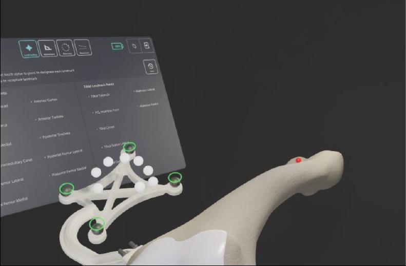
Tibial array and stylus should both be visible for tibial landmark capture. If need be, the user can hold the stylus tip to stabilize while capturing landmarks. Each landmark icon will initially illuminate “blue” to indicate the stylus is detected in a stationary state. Once the landmark is captured the landmark will turn “green.”


• Tibial Canal Entry
• Tibial Sulcus Medial
• Tibial Sulcus Lateral
• PCL Insertion Point
• Tibial Tubercle
• Medial Malleolus
• Lateral Malleolus

9.7.1


The tibial canal entry point is identified as the entrance point of the intramedullary canal. This point should be centered along medial/lateral axis. A/P positioning should fall between the middle and one-third of the anterior edge of the tibial plateau. Using the stylus, acquire the tibial canal entry point. The tibial array and stylus should be visible.
9.7.2

Medial and lateral tibial sulcus landmarks should both be captured from a similar viewpoint. The medial and lateral plateau resection references are used to compute the resection level, i.e., the planned tibial proximal resection will be below the acquired points. Using the stylus, acquire the lowest point of the medial/lateral tibial plateau. The tibial array and stylus should be visible.
The neutral rotation is defined by a point in the middle of the PCL insertion area on the tibial plateau and one on the medial third of the tibial tuberosity. This axis should lie perpendicular to the posterior edges of the proximal tibia. Using the stylus, acquire the PCL insertion area. The tibial array and stylus should be visible.
9.7.5

Using the stylus, acquire a point on the medial third of the tibial tuberosity. The tibial array and stylus should be visible.
To recreate the mechanical axis of the tibia, two points are digitized on the medial and lateral malleoli. The varus/valgus and flexion/extension values are computed relative to the mechanical axis. Using the stylus, acquire the medial and lateral malleoli in the surgeon’s preferred order. The tibial array and stylus should be visible.
Once the femoral and tibial landmarks have been acquired, the surgeon should proceed to Assessment Mode.

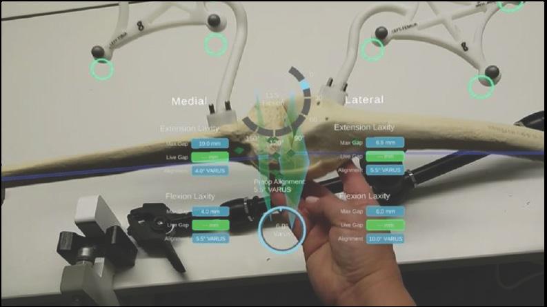

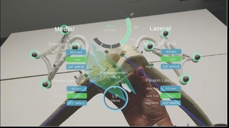
After acquiring all landmarks, the surgeon can now progress to Assessment Mode. The surgeon can move the operative knee through a series of tracked movements of the leg to assess the patient’s knee. STELLARTM Knee System will quantify, display, and temporarily save various characteristics of the knee condition.
The goal of this step is to assess limb alignment and knee balance. Combined with the information obtained during landmarking, the data acquired during this step is used to create a balance graph, which is adjusted in Balance Mode to create the desired final alignment and balance of the knee. If gap balancing is not desired, this step may be skipped.
1. Range of Motion: A movement of the leg is required to initiate the procedure. The surgeon can perform the range of motion test that will capture the minimum and maximum flexion angles of the knee. The alignment of the leg is also displayed.
2. Laxity Test: Knee laxity is measured in both extension and flexion. The user can assess laxity from -5 to 5° in extension and from 85 to 95° in flexion. The maximum varus/valgus angle values are recorded in the indicators for each angle. The amount of varus/valgus stress applied should represent the surgeon’s desired final tension in the medial and lateral collateral ligaments.
3. Distance: STELLAR Knee System displays the maximum distance of the medial and lateral compartments in millimeters with the knee in extension between -5° and 5° and in flexion between 85° and 95°.
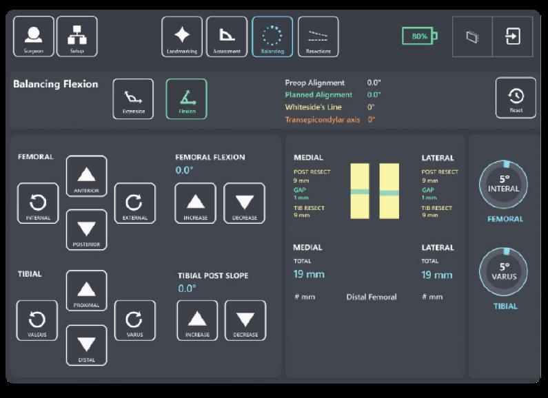
9.9 Balance Mode
Planned alignment and resection depths are determined automatically based on data acquired during landmarking and assessment, along with preferences set by the surgeon. In Assessment Mode, the intended medial and lateral ligament tension in extension and flexion were recorded. The goal of Balance Mode is to adjust the resection depths to modify the extension and flexion gaps to obtain the intended ligament tension.
In Balance Mode, the STELLAR Knee application is used intraoperatively by the surgeon to set femoral and tibial bone resections simultaneously by adjusting bone resections. The STELLAR Knee application will allow for a virtual understanding of the surgeon’s desired leg alignment, resection depths, and knee balance prior to making a resection. Ensure the femoral rotation value is set at a value achievable with implant system instrumentation. Ensure the posterior femoral resection depths match the desired posterior resections of the chosen implant system.

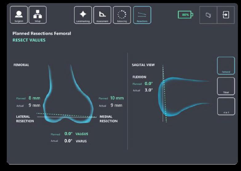
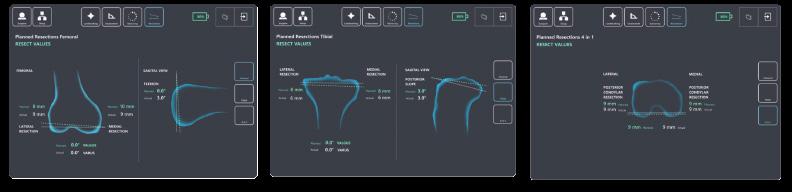
9.10 Resection Mode
Distal Femoral Resection Adjustment Buttons
see: Extension balance screen for image
• Femoral Varus
• Femoral Valgus
• Proximal Resection Depth
• Distal Resection Depth
• Femoral Flexion Increase and Decrease
Proximal Tibial Resection Adjustment Buttons
see Extension and Flexion balance screens for image
• Tibial Varus
• Tibial Valgus
• Proximal Resection Depth
• Distal Resection Depth
• Tibial Posterior Slope Increase
• Tibial Posterior Slope Decrease
Femoral Rotation Adjustment Buttons
see Flexion balance screen for image
• Posterior Condylar Resection Depth
• External/Internal Rotation Increase and Decrease
After completing requirements during balancing, the surgeon can now progress to Resection Mode. In Resection Mode, the STELLAR Knee application is used intraoperatively by the surgeon to locate femoral and tibial bone resection planes defined during balancing. Based on the intraoperative planned values, the STELLAR Knee application and fin instrument will now provide guidance to the appropriate resection plane positions to execute the resection plan for distal femoral, proximal tibial, and posterior condylar resections.
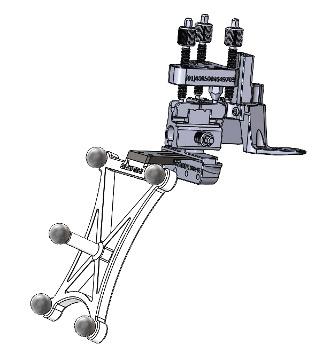
Universal Resection Guide (Femoral and Tibial Resections)
The Universal Resection Guide is used in performing resections of both left and right knees and both femur and tibia.
Warning: Care should be taken to not cause damage to resection guides and blocks when handling.
Warning: Only use the fin tool in resection slots that meet PolarisAR standard size requirements.
9.10.1 Distal Femoral Resection
1. Set the universal resection guide paddles on the distal femoral condyles.
2. Slide the headed pin (6.0mm) through the universal resection guide.
3. Drill the headed pin into the distal femur (2.5-3.5cm). Do not fully seat the headed pin. Page 32 of 40
4. Adjust the universal resection guide in a neutral rotation position.
5. Affix the universal resection guide on the bone by fully seating the headed pin. If additional fixation is preferred, the surgeon can use 3.5mm x 33mm or 3.5mm x 50mm headed pins in one of the fixation holes.
Warning: Shorter headed pins should be used to secure the universal resection guide to the bone through the feet. If longer pins are needed, care should be taken to not protrude through the posterior cortex of the bone.
Caution: Care should be taken not to over seat the headed pin.


6mm x 80mm Head Pin
3.5mm x 33mm Head Pin


Install the femoral resection block using the key feature on the anterior aspect of the universal reference toward the distal femoral condyles. Set the resection block away from the bone and lock it into place using the locking screw. Depending on patient anatomy and surgeon preference, two holes are provided on the Universal Resection Guide for the Locking Screw to adjust the range of Resection Block locking positions. The Locking screw can be placed in either of the holes by unscrewing it fully from the current hole and resecuring it into the desired hole.
6. Install the STELLAR Knee fin into the distal femoral resection block slot Ensure the fin is fully seated.
7. Once the fin is fully seated, follow guidance feedback on the headset screen with the goal of overlaying the actual femoral resection plane (white) to the planned femoral resection plane (green).
8. Reticle use: Use the reticle display to align the blue femoral marker circles with the green femoral array circles for the best position to capture the resection values. The fin marker circles and the femoral array circles should both be centered in the reticle as much as possible. The small UI panel on the anatomy will adjust to reflect the angles where the landmarks were captured.
9. Adjustments can be made to resection depth, flexion/extension, and varus/valgus using the respective knobs.
10. Once the actual plane is overlayed to the planned plane, the fin can be removed, and the femoral resection block can be pinned in position for resection.
11. Insert two Fluted 3.2mm Straight Pins in the base of the femoral resection block using both parallel, A/P holes. Fix the parallel pins first, ensure the guide is against the bone, and follow it up with a cross pin before removing the resection guide.
12. Remove the entry headed pin.
13 Remove the universal resection guide.
14 Install the STELLAR Knee fin into the femoral cut guide ensuring the fin is fully seated. Ensure the actual femoral resection plane (white) and the planned femoral resection plane (green) are correctly overlayed before resecting the femur.
15. Resect the distal femur.
Caution: The instruments must remain stable and properly fixated to the bone to ensure the accuracy of the system.
Warning: Check guide position before making resections.
Warning: Check guide position resection screen after pinning guide but before cutting.
9.10.2 Distal Femoral Resection Validation
Position the flat surface of the fin onto the distal femoral resection. The distal femoral resect values are displayed on the screen.
Warning: Validate the applicable resection to confirm actual resection matches planned resection.
9.10.3 Proximal Tibial Resection
1. Set the resection guide paddles on the proximal tibial plateau.
2. Slide the entry headed pin (6.0mm) through the universal resection guide.
3. Drill the entry headed pin into the proximal tibia (2.5-3.5cm). Do not fully seat the entry headed pin.
4. Adjust the universal resection guide in a neutral rotation position.
5. Affix the universal resection guide on the bone by fully seating the entry headed pin. If additional fixation is preferred, the surgeon can use 3.5mm x 33mm or 3.5mm x 50mm headed pins in one of the fixation holes. Caution: Care should be taken not to over seat the headed pn.
6. Install the tibial resection block using the key feature on the anterior aspect of the universal reference toward the proximal tibia. Set the resection block away from the bone and lock it into place using the locking screw. Depending on patient anatomy and surgeon preference, two holes are provided on the Universal Resection Guide for the Locking Screw to adjust the range of Resection Block locking positions. The Locking screw can be placed in either of the holes by unscrewing it fully from the current hole and resecuring it into the desired hole.

7. Install the STELLARTM Knee fin into the tibial resection block slot. Ensure the fin is fully seated. Page 34 of 40
8. Once the fin is fully seated, follow guidance feedback on the headset screen with the goal of overlaying the actual tibial resection plane (white) to the planned tibial resection plane (green).
9. Adjustments can be made to resection depth, posterior tibial slope and varus/valgus using the respective knobs.
10. Once the actual plane is overlayed to the planned plane, the fin can be removed, and the tibial resection block can be pinned in position for resection.
11. Insert two Fluted 3.2mm Straight Pins in the base of the femoral resection block using both parallel, A/P holes. Fix the parallel pins first, ensure the guide is against the bone, and follow it up with a cross pin before removing the resection guide.
12. Remove the entry headed pin.
13. Remove the universal resection guide.
14. Install the STELLAR Knee fin into the femoral cut guide ensuring the fin is fully seated. Ensure the actual femoral resection plane (white) and the planned femoral resection plane (green) is correctly overlayed before resecting the femur.
15. Reticle use: Use the reticle display to align the blue circles of the tibial marker with the green circles of the tibial marker. Both the fin array circles and the green array circles should be centered in the reticle as much as possible for best tracking. The small UI panel on the anatomy will adjust to reflect the angles where the landmarks were captured. Ensure the actual tibial resection plane (white) and the planned tibial resection plane (green) are correctly overlayed before resecting the tibia.

16. Resect the proximal tibia.
CAUTION: The Instruments must remain stable and properly fixated to the bone to ensure accuracy of the system.
9.10.4 Proximal Tibia Resection Validation
Position the flat surface of the fin onto the proximal tibia resection. The proximal tibia resect values are displayed on the screen.
The femoral and tibial resection blocks are compatible with saw blades of 1.27mm (0.05”) thickness.
Femoral Posterior Condylar (4:1) Resection
1. To perform 4:1 resections with the STELLAR Knee System, the surgeon must first understand the following:
a. Femoral Implant Posterior Condylar Thickness (mm)
b. Proximal Tibial Implant Thickness (mm)
c. Tibial Insert Thickness (mm)
Femoral 4:1 Resection guides are specific to the knee implant system being used. In combination with the STELLAR Knee fin, the STELLAR Knee application will assist in guiding the surgeon to the defined posterior condylar axis for performing posterior condylar resection.
9.11 Performing 4:1 Resection with Femoral Implant Lug Holes
1. Using the knee implant system Femoral AP Sizer, enter femoral rotation (degrees) planned during Balance Mode.
2. Using the knee implant system Femoral AP Sizer, perform surgical protocol consistent with that system’s surgical technique, including femoral sizing and lug hole prep.
3. Select the desired size femoral 4:1 resection guide from knee implant system standard instrumentation.
4. Impact the femoral 4:1 resection guide per the knee implant system surgical technique.
5. Insert the STELLAR Knee fin into either the posterior or anterior resection slot of the selected 4:1 resection guide. Ensure the fin is fully seated.
6. Ensure the posterior condylar resection depths and plane is consistent with what was planned in Balance Mode.
7. Once the Actual Plane is validated to the Planned Plane, the fin can be removed, and the Femoral 4:1 Resection Block can be pinned into position to perform the four resections.
8. The surgeon should follow the knee implant system’s recommended 4:1 sequence.
Perform remainder of femoral and tibial preparation (e.g., keel punch) per knee implant system surgical technique.
10 SYSTEM DISASSEMBLY
10.1 Post-operative Guide
System Shutdown
Caution: Do not exit STELLAR Knee application until procedure is complete.
Exit the STELLAR Knee application by touching the exit button in the sub menu. Turn off the headset by pressing the on/off button on the headset and holding for 5 seconds. All five lights will light up and fade off one by one. Recharge the headset before every procedure. Please see HoloLens 2 documentation.

10.2 Equipment Inventory and Cleaning/Sterilization Methods
1. Headse t
2. Case
3. Charger
10.2.1 STELLAR Knee Headset
HoloLens 2 Cleaning and Care
a. Cleaning – The device should be wiped clean with a soft cloth. Never use lens cleaners on the HoloLens 2 visor.
b. Remove any dust by using a dry, lint-free microfiber cloth to gently wipe the surface of the device.
c. Use the included HoloLens lens cloth to gently wipe the lens.
d. Lightly moisten the cloth by using medical 70% isopropyl alcohol, and then use the moistened cloth to gently wipe the surface of the device.
e. Let the device dry completely.
f. To clean the brow pad, use water and mild soap to moisten a cloth and gently wipe the brow pad. Let the brow pad dry completely. g. Detailed information on cleaning your HoloLens 2 can be found here: https://docs.microsoft.com/en-us/hololens/hololens2-maintenance
STELLARTM Knee
Reusable Instrumentation
• Headed Pin
• Universal Resection Guide • Resection Block 1. Femoral 2. Tibial (Left and Right) • Hudson Adapter (used w/Hudson power adapter)
• Pin driver
10.2.2 Sterilization Instructions
STELLAR Knee Disposables (included in Kit) Knee Implant System and General Equipment Requirements
• Stylus
• Femoral Array (Left and Right)
• Tibial Array (Left and Right) • Fin • Array Pins (Qty 7)
• Resection Block Pins (Qty 3)
• 4:1 Resection Guide
• 4:1 Resection Guide Compatible Pins
• Trial Implants (femur, tibia, tibial inserts)
• Modified Hudson Adapter • Saw Blade Thickness: 1.27mm
• Retraction Instrumentation (surgeon preference)
The Stellar Knee Reusable Instrument Tray is only intended to maintain sterility of the enclosed devices if it is used in conjunction with an FDA-cleared sterilization wrap and has only been evaluated for a non-stacked configuration. The tray is intended to allow steam sterilization of the enclosed medical devices. The validated sterilization cycle parameters are as follows:
Pre-vacuum 132°C (270°F) 4 minutes 30 minutes
These cleaning and sterilization instructions have been validated as being capable of preparing these reusable instruments for reuse. It is the responsibility of the healthcare facility to ensure that the reprocessing is performed using appropriate equipment, materials, and personnel to achieve the desired result. This normally requires validation and routine monitoring of the process. Any deviation by the healthcare facility from these instructions should be evaluated for effectiveness and potential adverse consequences.
10.2.3 Reprocessing Instructions
Initial treatment at point of use
Do not allow contaminated devices to dry prior to reprocessing
Transportation to reprocessing area
Do not let contamination dry and transport without risk of cross-contamination
Manual cleaning Cleaning agent Accessories
• Instruments should be cleaned within 30 minutes of use to prevent drying prior to cleaning. Do not allow contaminated devices to dry prior to reprocessing, e.g., remove gross debris by wiping with a lint-free cloth. • Place the instruments in the sterilization tray for further transport and cover with a damp towel to prevent drying of contamination.
• Place the instruments in the sterilization tray for further transport and prevent organics from drying e.g., cover with a damp towel to prevent drying of contamination.
• Prepare and use a cleaning agent concentration and temperature specified by the detergent manufacturer. • As an example, prepare a minimum concentration of 0.1 % Prolystika 2x concentrate (enzymatic cleaning agent) used for presoaking and ultrasonification cleaning.
• washing bin • lint-free clean wiping cloths • soft bristle brush: - surface brushes in different sizes
Process stage Relevant Aspect

Procedure

Inspection and maintenance Detection of possible residues of cleaning agent or damage of the device, test for functionality
Packaging parts for sterilization
- bottle brushes in different sizes
Instruction
• Remove excess fluids or tissue from the instruments with a sterile disposable, non-shedding/lint-free wiping cloth. • Place instruments in the bin with the prepared handwarm cleaning solution, e.g. Prolystika 0.1 % (1 mL cleaning detergent in 1 L water) and soak for 5 min. • Scrub with soft bristle brushes to remove all visible soil on all accessible surfaces. Pay close attention to threads, joints, crevices, seams, and any other hard-to-access areas. Use bottle brushes with an appropriate size to scrub blind holes, crevices, lumens, etc., to remove debris from inner surfaces. Actuate any moving mechanisms to free trapped blood and debris. Rinse with the cleaning solution. • Remove instruments from the cleaning solution. Rinse in running (tap) water for 3 minutes or until all traces of cleaning solution are removed, whichever is longer. Thoroughly and aggressively flush lumens, holes, crevices, threads, joints, and all other hard-to-access areas. • Prepare an ultrasonic bath with an enzymatic detergent at the concentration and temperature specified by the detergent manufacturer, e.g., Prolystica Ultra Concentrate 2x Enzymatic 0.1 % at 35 +/- 3°C. • Completely submerge instruments in ultrasonic cleaner with prepared enzymatic solution. Clean under ultrasonification for 5 min at 35 kHz +3.5, -0.5. • Remove instruments from the ultrasonic bath and rinse instruments in purified water for 3 minutes or until rinse stream is clean of blood or soil, whichever is longer. Thoroughly and aggressively flush lumens, holes, crevices, threads, joints, and all other hard-to-access areas.
• Let the instruments dry.
Visually inspect each device for remaining soil. If soil remains repeat the ultrasonic cleaning process step. In addition, inspect visually dryness and inspect for possible damage: • Un-magnified visual inspection under good lighting conditions is sufficient. • All parts of the devices should be checked for visible soil, discoloration, and/or corrosion. Particular attention should be paid to: - Soil “traps” such as mating surfaces, hinges, and threaded features. - Recessed features (holes, cannulations).Features where soil may be impacted into the device, such as drill flutes adjacent to the cutting tip. Cutting edges should be checked for sharpness and damage. • For devices that may be impacted check that the device is not damaged to the extent that it malfunctions or that burrs have been produced that could damage tissues or surgical gloves. • Functional checks should always be performed: - Mating devices should be checked for proper assembly. - Instruments with moving parts should be operated to check correct operation (medical grade lubricating oil suitable for steam sterilization can be applied as required). - Rotating instruments, such as multiple-use pins and screws, should be checked for straightness. This can be achieved by simply rolling the instrument on a flat surface. Parts should only be used if all visual and functional inspections are completed and passing. Parts should not be used for more than 500 surgeries.
• Place the cleaned, dried, and inspected parts in the sterilization tray. • Refer to section 12.2.2 for sterilization instructions.
11 STORAGE AND TRANSPORT
11.1 Array and Guides Storage and Transport
The arrays and instruments shall remain protected from all impacts during handling and storage. Arrays should not be stored in a location where they receive frequent vibration or movement as this could affect calibration accuracy.
11.2 HoloLens 2 Storage and Transport
The HoloLens 2 should be stored and transported in its protective case according to Microsoft instructions which can be found here: Microsoft HoloLens | Microsoft Learn
12 SERVICE AND MAINTENANCE
The HoloLens 2 device should be maintained according to the HoloLens 2 care instructions. Please contact your PolarisAR representative for service and maintenance concerns.
Caution: There are NO user-serviceable parts. Return HMD and instrumentation to PolarisAR for service.
Caution: Properly dispose of the lithium battery by returning the HMD to PolarisAR .
13 CYBERSECURITY
• All data acquired through the system during use is anonymous and is deleted upon application shutdown and/or restart.
• Device is configured to prevent unauthorized access and updates are performed through USB port rather than through the internet.
• Each device is intended for a single user. No shared accounts are permitted. Do not share your HoloLens 2 or passwords.
• Device should be stored in a secure location to ensure no unauthorized access to the system is obtained.
14 TROUBLESHOOTING
If the system fails unexpectedly, proceed as follows:
1. If resections have been started, complete the case using conventional manual procedure.
2. If the STELLARTM Knee application does not restart or function as expected, proceed with manual procedure, and contact your PolarisAR representative for additional help with troubleshooting the system.
15 MRI COMPATIBILITY
Safety in MRI Not Evaluated: The STELLAR Knee system is not intended to be used in the MRI environment as it is only intended to be used in the operating room.
16 GLOSSARY
Array - An array of fiducials with a known geometric arrangement, used for tracking object locations in up to 6 degrees of freedom.
Augmented Reality - is an interactive experience of a real-world environment where the objects that reside in the real world are enhanced by computer-generated perceptual information, sometimes across multiple sensory modalities, including visual, auditory, haptic.
Fiducial - An object whose center is identifiable within a 2-dimensional image.
HMD – Head Mounted Display
Reference Array - An array that serves as a relative reference for identifying the location of a second array.
User Interface - All points of interaction between the user and the device, including all elements of the device with which the user interacts (i.e., those parts of the device that users see, hear, touch). All sources of information transmitted by the device (including packaging, labeling), training and all physical controls and display elements (including alarms and the logic of operation of each device component and of the user interface system as a whole).
Originator
Jacob Brenza 00 23-054 Initial release 20-JUL-2023
Caroline Via 01 23-062 Highlight warning, add voice commands to make full list, correct equipment inventory list 30-SEP-2023
Caroline Via 02 23-065
Change word “intended” to “indicated” in indications for use Remove “Software As a Medical Device” in intended use 7-NOV-2023
Jacob Brenza 03 23-069 Updated instructions and images for updated part designs. 13-FEB-2024
