Awnili Shabnam

OVERSEAS QUALIFICATIONS ASSESMENT PORTFOLIO
CONTENTS
PROJECT 1 OCEANOGRAPHIC RESEARCH CENTER
Coxbazar, Chittagong, Bangladesh
PROJECT 2 DESIGN OF A COMMERCIAL HIGHRISE BUILDING
Hatirjheel, Dhaka, Bangladesh
PROJECT 3 HOUSING FOR LOW INCOME GOVERNMENT EMPLOYEES
Azimpur,Dhaka, Bangladesh
PROJECT 4 2-STORIED FAMILY RESIDENCE AT MUKUNDA MADHUSUDANPUR
Satkhira,Kaligonj,Khulna, Bangladesh
PROJECT 5 BONOCHAYA INTERIOR
Basundhara,Dhaka, Bangladesh
PROJECT 6 IHUB NETWORK
Basundhara,Dhaka, Bangladesh
MISCELLANEOUS
3
04-15 16-23 24-33 34-53 54-65 66-71 72-79
OBJECTIVES
• Provide and utilization of this knowledge for inventory and exploration of marine resources and protection of the marine environment.
• Ensure sustainable extraction of petroleum resources without disturbing the ecological balance
• Extend co-operation to all organizations and academic institutions of the country
• involved in the study of Marine sciences and to provide shipboard facilities to them for carrying out observations to the sea
• Detect different environmental issues ( Coast, deep sea circulation, island formation, water flow etc.) and to detect environmental hazard (Oil spelling, dumping, blast water, deforestation effect etc.) and climate issues ( Co2, O3 layer, ice melting, coral destruction etc.)
• Study oceanographic parameters which influence the distribution and abundance of fisheries resources, shrimp and mollusks
• Develop coastal aquaculture and mariculture
• Use of wind, wave, water, temperature and other alternative sources of energy from the sea
• Generate employment opportunities in mariculture and related trading.
• Promote tourism and recreation by the establishment of sea parks and marine aquarium etc.
FACTORS
• Construction cost: The hilly terrain of the site will cause additional expenditure and complexity in construction
• Construction technology: The Aquarium and research facilities will need innovative construction technologies to accomodate diverse functions
• Aquisition and transport of equipment: Aquisition of state-of-the-art equipment for research labs and establishing an efficient workflow for mechanical systems will add up to the cost
• Environmental issue: The land is adjacent to the Bay of Bengal is prone to flood and landslide
• Navigability: Navigability of the waterway has to be ensured so that the research vessels can travel through
• Adjacent tourist facility: Mermaid Eco-Resort, adjacent tourist facility provides an opportunity to acquire potential visitors for the Aquarium and other activity spaces
PROJECT 1 OCEANOGRAPHIC RESEARCH CENTER
Final Project
Bachelor of Architecture
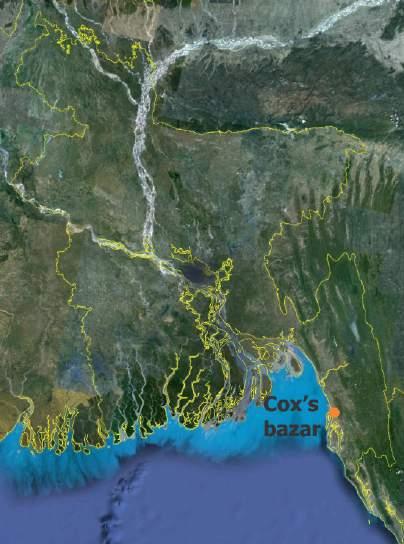
Location: Coxbazar, Bangladesh
Time period : July-November, 2013
Individual project
BACKGROUND
Diverse and abundant marine and coastal life forms and mineral and petroleum resources as well as the potential use of tidal and wave energy is becoming increasingly important to ensure the socio-economic development and full filling the strategic objective of the country. So the country has a long way to go for proper utilization and management of her marine and coastal resources for national flourishing and sovereignty with an integrated and holistic approach. A platform is to be created to provide an opportunity for studying the physical and dynamic process of the sea in various fields of oceanography, to facilitate exploration and exploitation of sea resources.
A proposal to build Oceanographic Research Center in Cox’sbazar was approved and funded by Ministry of Science and information and communication Technology. The project was formulated and designed as final project of Bachelor of architecture considering actual client, site and construction constraints.
PC 1.2 : Establishment, analysis and evaluation of client project requirements and objectives
After several meeting with client and analysis of the socio-economic background of the project a list of objectives was set up as a guideline prior to design.
PC 1.4 : Identification of factors that may impact on client project requirements and objectives.
Based on careful analysis of the topography of the land, existing landuse pattern, functional requirment and environmental condition several factors impacting the project were identified.
5
PROJECT 1 OCEANOGRAPHIC RESEARCH CENTER
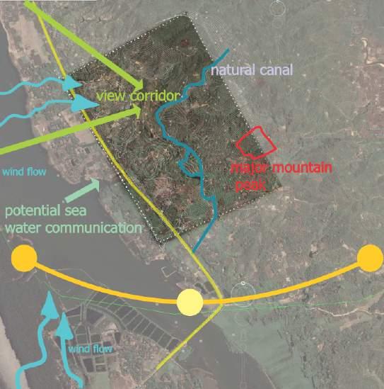
PC 2.1 : Identification, analysis and integration of information relevant to siting of project

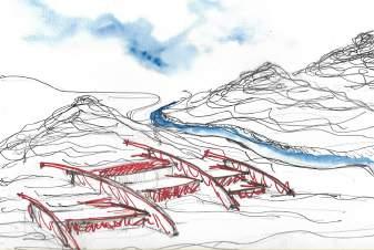
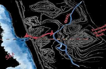
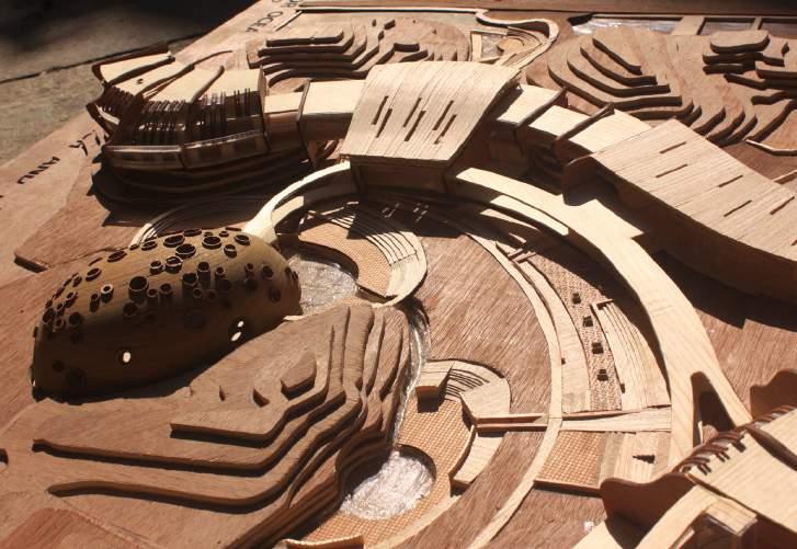
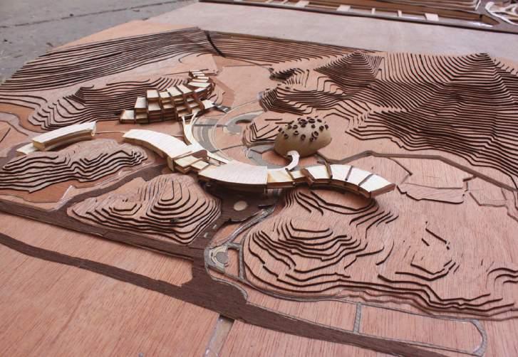
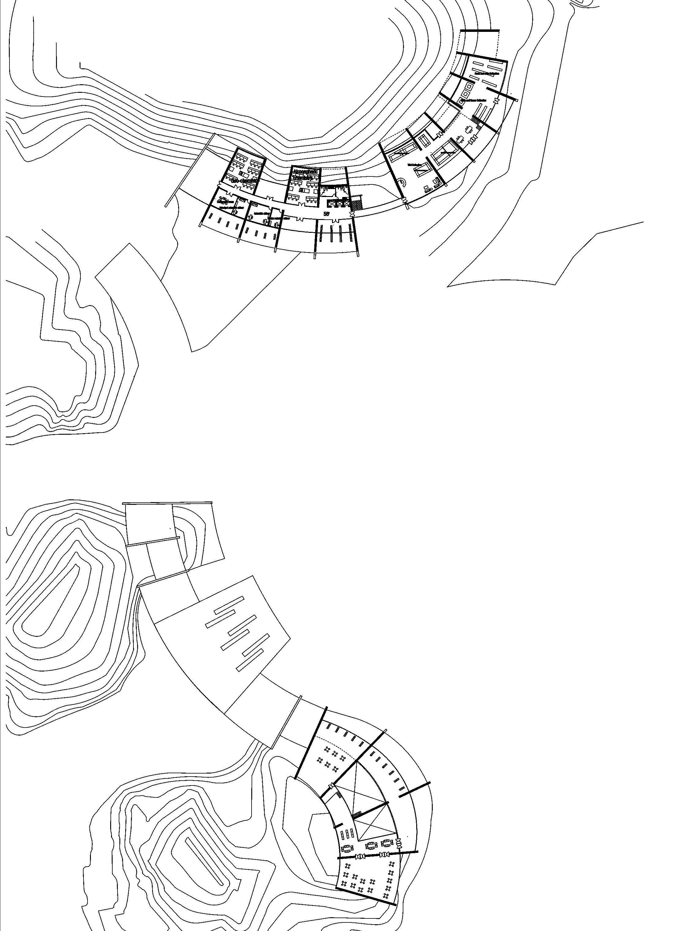
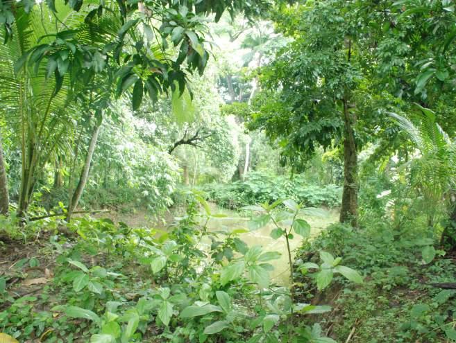
Fig 2 demonstastrates the analysis of the site outlining key features that can be manipulated to the advantage of project sitation. The narrow canal between two patches of lands can be a potential source of sea water that can be easily collected and distributed throughout the functional spaces like water tanks, touch pools and aquariums. The natural fountain flowing from the hill tracts can be a guiding element to shape recreational activities. The view corridors emerging between two mounds can be impactful in the spatial configuration of form and functions. The major mountain peak offers an elegant directionality to the project.
Fig 3 shows specific height of the contours and predominantly flat areas assisting in making effective design decisions

Fig 4 shows existing structures, plant arrangements, location and area of waterbodies and canals,existing service lines etc.
6
Fig1: Site location
Fig3: Site Contour
Fig2: Site Analysis
Fig 4: Site Topography
DESIGN CONCEPT/ CONSIDERATION
• Provide a platform for sustainable exploration and exploitation of sea resources.
• Create awareness for oceanic conservation.
• Develop an institute that itself becomes a tool for motivation researchers, visitors and community.
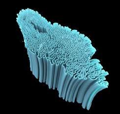
The ocean and it’s importance to earth and humanity
PROJECT 1 OCEANOGRAPHIC RESEARCH CENTER
PC3.1: Design response integrates the objectives of brief, user intent and built purpose

The design concept was developed after careful analysis of the objectives of the brief, user intent and built a purpose.
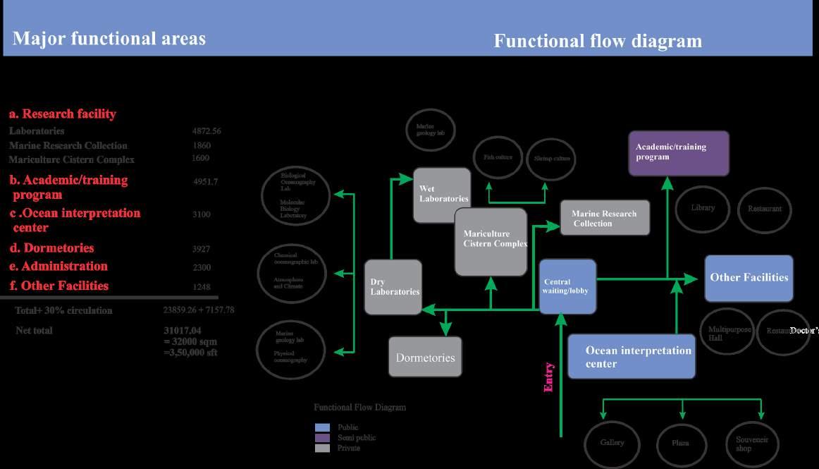
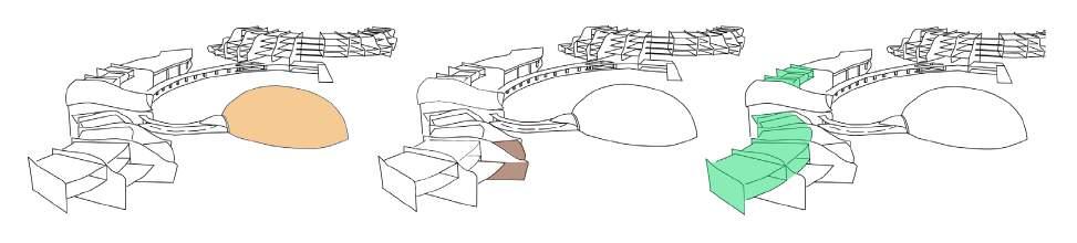
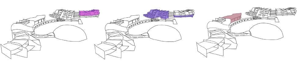
Fig 7 shows the formulation of programs based on intented functions. Major functional areas were identified and adequate space was allocated to them. Responding to the primary objective of the brief, that promotes oceanographic research, adequate dry labs, marine reasearch collection, and mariculture cisturn complex was proposed. Ocean interpretation center was dedicated to creating awareness among visitors and tourists. Other supporting facilities such as Academic, administrative and residential amenities were planned according to the brief.
The ocean with all its depth and complexity
Scientists, students, decision- maker and public
PC 3.3: Design Response incorporates assessment of the physical location and relevant wider regional , contexual and environmental issues
The site of the project situated is situated in the hilly region of Coxbazar, descending down towards the Bay of Bengal. Design concept was developed addressing the contours of the land and also considering the flood vulnerability of the region.
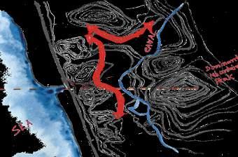
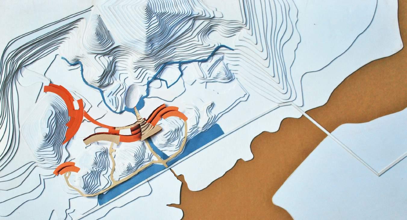
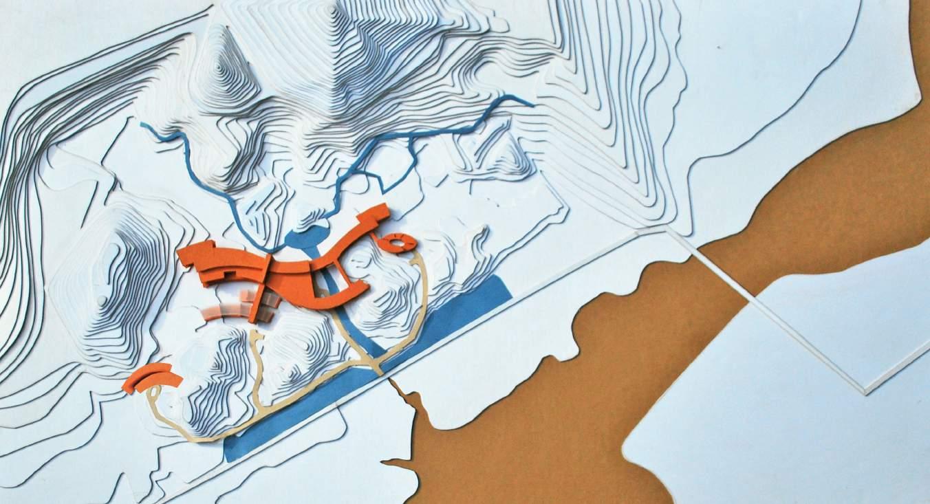
Fig 5 Indicates the site has sea beach on the east side and a natural fountain flowing down from mountains through the middle part. An artificial water connection was proposed to relate to natural water bodies developing a visual and physical directionality towards major mountain peak Fig 6 shows the derivation of forms following the contours and also leaving out spaces to create a natural path to drain out excess rainwater.
Integration Of Natural Forces Development Of Formal Expression
7
Fig 5: Relate two natural water bodies with artificial connection and create focus towards major peak
Fig 6:The from was inspired from the curve profile of the terrain site both in plan and elevation
Understand Explore Educate
Fig7:functional flow diagrm
PROJECT 1 OCEANOGRAPHIC RESEARCH CENTER
PC 3.2: Application of creative imagination, aesthetic judgement and critical evaluation in formulating design options.
Multiple design options were developed cosidering feasibility of constructuion,cost, functional efficiency and spatial experiences.
Option 1(Fig 8) shows placement of forms covering most of the flat lands surrounded by the hills.The design option provides advantage in terms of construction cost and complexity as earth excavation and erection of foundation is easier in flat lands. But it also interferes with the natural drainage of rainwater flowing from the mountains.
Option 2 (Fig 9) shows layered placement of forms along the contours of the hills opening up scope of natural flow of rainwater over the flatland.
PC 3.6: Assessment of the economic impact on the project of design strategies and options.
Each design approach had its pros and cons in terms of economic feasibility. Option 1 suggested most of the construction on the flat land and not much higher than the road level. Cost of material transport and water management was less expensive. However, locating the building on that land would make it vulnera-ble to flooding caused by excessive rainfall. Surrounding mountains and highland would not let the rainwa-ter to naturallly flow towards the sea. Expensive and highly maintained drainage system had to be devel-oped. So, option 1 wasn’t cost effective in the long term scenario.
Option 2 proposed the construction on top of high contours. Transport of materials, erection of foundation and flattening of the earth in places would increase the cost substancially. However, this would reduce the risk of flood and extensive cost of damage control afterwards.
Option 1
Option 2
8
Fig 8: Formal configuration considering ease of construction.
Fig 9 : Formal configuration considering flood vulnerability
PROJECT 1 OCEANOGRAPHIC RESEARCH CENTER
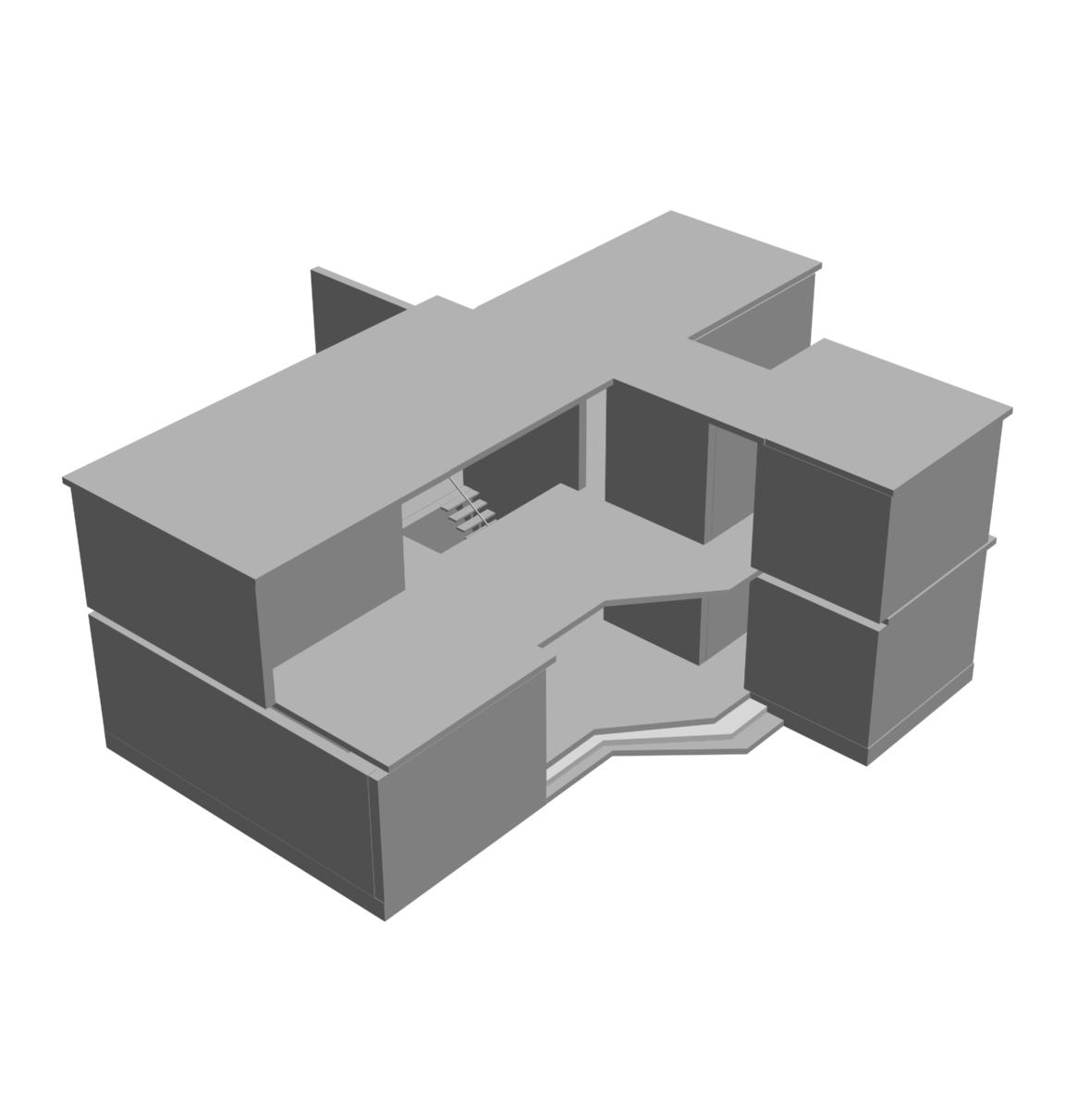
PC3.5: Exploration and application of ordering, sequencing and modelling of three-dimensional form and spatial content.
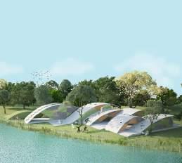
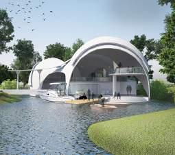
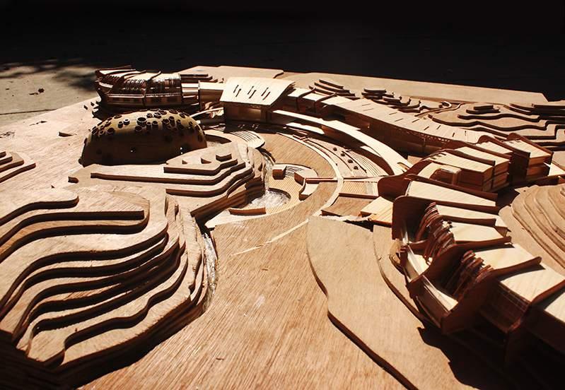
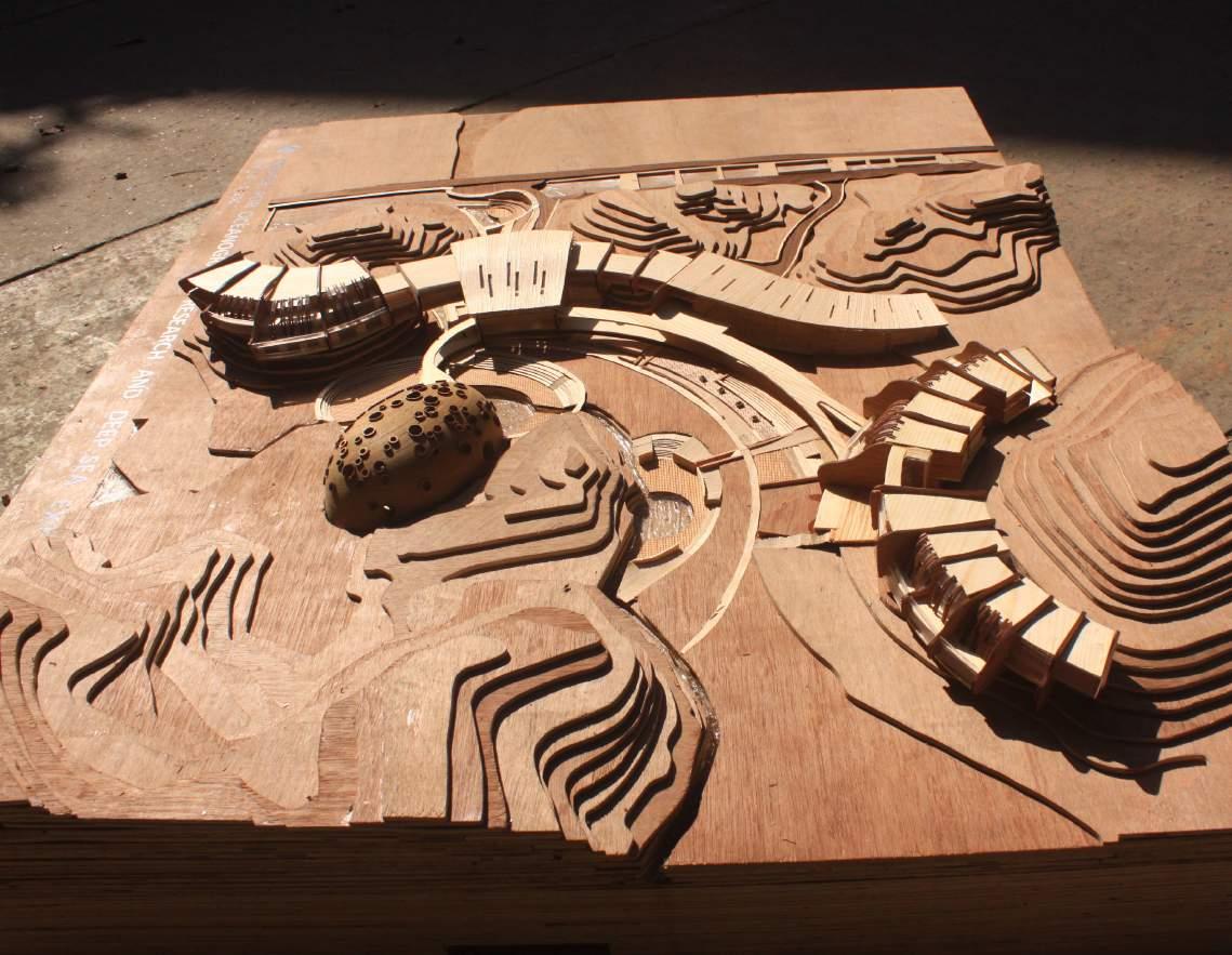
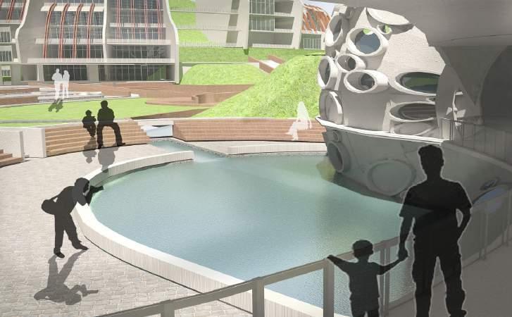
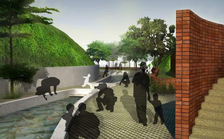
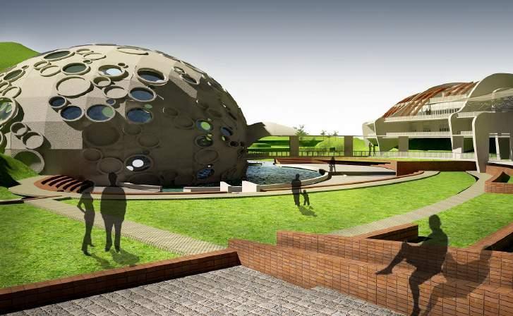
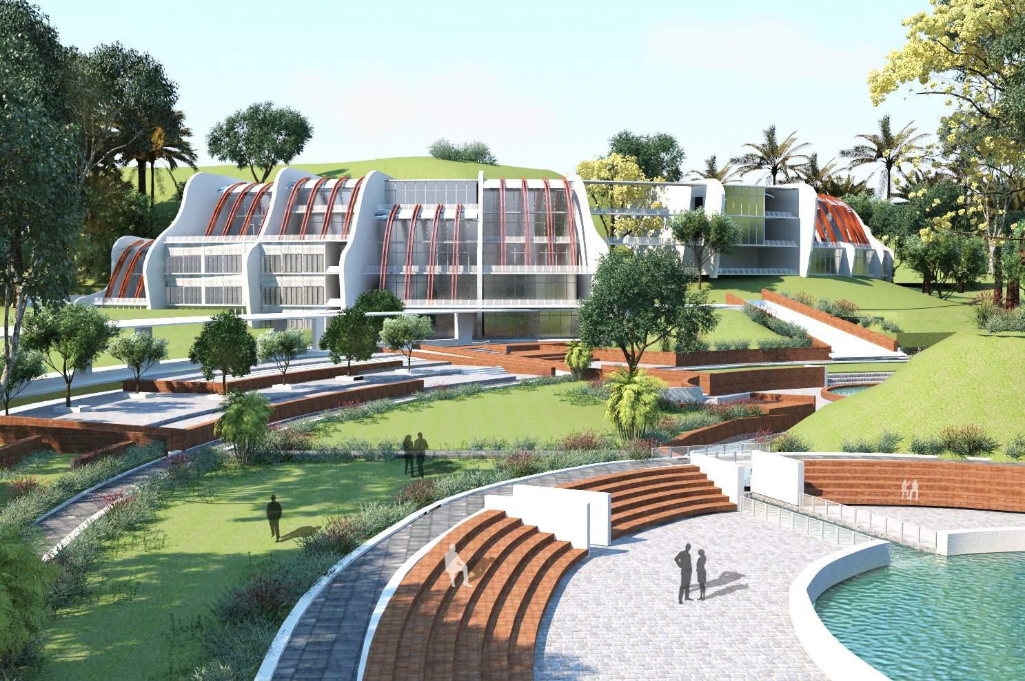
Three dimensional form of the complex derived from the natural contour of the land. The fountain flowing from the hills was bleded with the lanscape creating meaningful breakout spaces for the students and researchers. Public, semipublic and private zones were defined by segmented mass, yet they were connected through the circulation spine and the central plaza. The central eliptical form of Ocean Interpretation Center developed the focal point of the complex-performing as the heart of attraction for tourists and visitors.
9
Fig11: View towards the central plaza
Fig13: Ocean Interpretation Center and adjacent plaza
Fig12: Entrance to the complex
Fig10: Physical model of the complex
PROJECT OCEANOGRAPHIC RESEARCH CEN- 1 CENTER
PC3.8: Application of manual and digital graphic techniques and modelling to describe threedimensional form and spatial relationships.
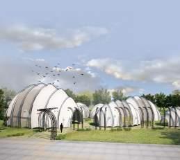
Fig: 14-17 shows a 3D visualisation of form and space using digital graphic techniques.3D studio max was used as modelling software and V-ray was applied as a rendering tool. Vray sun system was applied to produce real life shadow casting, reflection and expression of material properties.
10
Fig15: Ocean interpretation center- a space exhibiting and presenting features of deep Fig16: Touch pool guiding towards ocean interpretation center exhibiting mysterious and colorful animals beneath waters which visitors can touch and feel
Fig17: Plaza and reflecting pool in front of ocean interpretation space - vibrant with visitors
Fig14: Plaza and court in front of the dry laboratory - acting as a breathing space for researchers
PROJECT 1 OCEANOGRAPHIC RESEARCH CENTER
PC4.4: Inclusion of expertise of relevant specialists and consultants in developing the project design.
Researchers in Institutute of Marine Science and Fisheries, University of Chittagong were consulted before desiging the layout of wetlab. The lab focused on shrimp culture, which is an important sector to boost up the local economy. The local hatchery industry specialists also suggested tank capacity,aeranation, lighting and total environmental system.
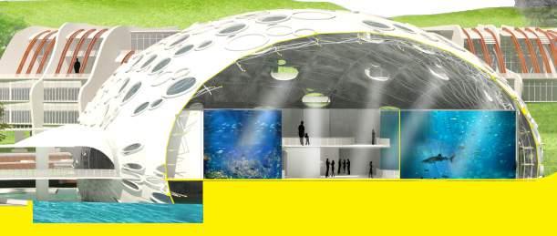
PC 4.7: Coordination and integration of appropriate environmental systems, including for thermal comfort, lighting and acoustics.
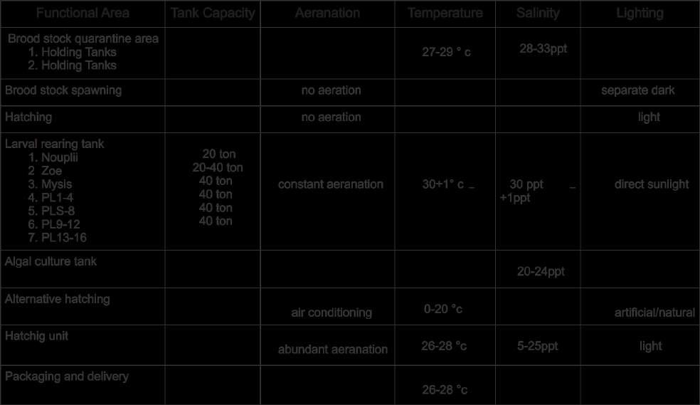
The wetlab focusing on shrimp culture needed to incorporate an integrated environmental system including aeration, temperature, salinity and lighting conditions. Appropriate broodstocks are collected from seawater and kept in maturation tanks. The process of collecting and hatching eggs from Broostock and rearing larvas in different stages needed carefully curated environmental systems and arrangements of tanks.
The Fig 19 shows the chart for tank capacity,aeranation, temperature, salinity and lighting condition for each stage of shrimp hatching.
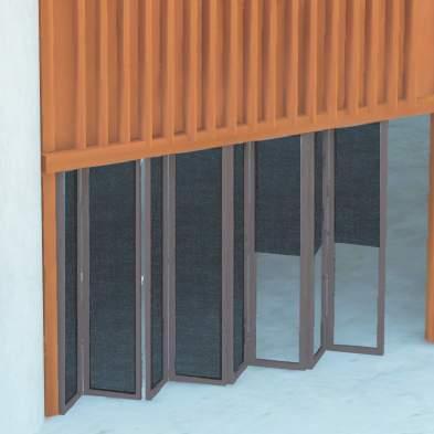
A flexible system was needed to control the lighting in different stages of shrimp hatching process. Case study in local hatcheries showed that they used black fabric to manually cover the chambers to contol the lights inside. The idea was incorporated in a more efficient way to develop a shutter system ( Fig18)
The blowup image in Fig: 18 shows the collapsable doors that can be extended and collapsed as per functional requirement. The operable black fabric shutter is attached on top of the glass panel to control the amount of light that can be allowed inside.
5.5 Integration of materials and components based upon an understanding of their physical properties.
Acrylic tunnels, windows were specified for shark & other fish tanks. Acrylic has excellent optical clarity and unlike glass, acrylic is perfectly clear and does not impart a green or smoky tinge. Along with this clarity with the material possess high impact resistance, durability and ease of refurbishment. These unique prop -erties are what make it the aquarium industry’s material of choice for underwater aquarium tunnels, view-ing windows, domes and curved panels. Best quality fibreglass reinforced polymer was suggested as the basis of applied aquarium waterproofing systems. It is essential that the system had crack spanning capaci-ty, durability and be completely fish safe and non-toxic to the marine environment ( Fig 20).
11
Algal culture tank
Brood stock Holding tank
Egg hatching tank
Larval rearing tank
Fig18: Wetlab Configuration
Fig19: Chart for tank capacity,aeranation, temp,salinity and lighting condition for each stage of shrimp hatching
Fig 20: Acrylic aquarium for marine life display.
PROJECT OCEANOGRAPHIC RESEARCH CENTER
PC4.5: Investigation and integration of appropriate structural, construction, service and transport systems in the project design.
&
PC 4.6: Investigation and integration of appropriate material selection for the project design

The main challenge was to find out appropiate structural system for the contoured land. The curve forms following the contours were segmented by concrete shear walls and connected with tie beams. Fair-faced finish was proposed considering its aesthetic appeal. Aluminium form work was specified to achieve a smooth appearance.
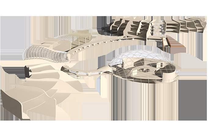
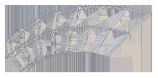
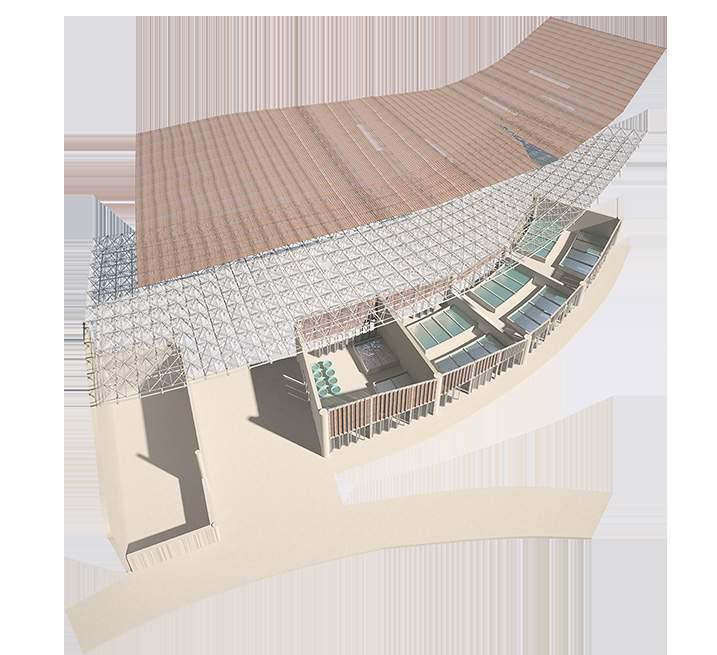
The central lobby and the wetlab had a large span of the area including multiple functional spaces. The forms needed a different structural system. Space frame curve roofs comprising of stainless steel nodes and members were designed to suit the need. The members were proposed to be prefabricated and transported from a local steel factory. There were two options for material and component transport- waterway and motorways. Motorway was preferred as the structure could be febricated in small segments and carried to the site to join together. A layer of corrugated fibre glass was placed to cover the roof, combination of translucent and opac depending on functional requirement (Fig21).
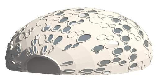
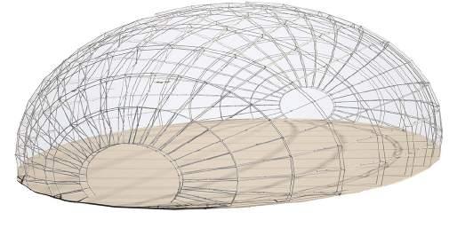
Ocean Interpretation Center composed of a spaceframe elliptical dome structure. The spaceframe was covered with PTFE panels considering its heat resistant properties. Translucent panels were used to invite skylights inside (Fig22a & 22b).
12
Steel space frame roof Covering larger span
Steel space frame dome
Shear wall
Fig21: Structural system of entire complex
Fig 22a: Steel space frame skeleton is fitted with lightweigh screening panels allowing light in interior space
1
Fig22b:Steel space frame skeleton acting as a framework for screening panels
PROJECT 1 OCEANOGRAPHIC RESEARCH CENTER
PC 5.1: Application of creative imagination and aesthetic judgement in producing a resolved project design in regard to site planning, physical composition and spatial planning as appropriate to the project brief.
The site planning emphasized on the most beneficial use of natural element and resources: seawater,natural fountain and contourland. A network of water spread through the complex fulfilling both aesthetic and funcional purposes.Seawater treatment units and outdoor cisterns were conveniently placed in a belt parallel to Marine Drive and near the source of sea water to optimize the cost of transporting water.A series of touchpools were arranged guiding the tourists and visitors towards ocean interpretation center exhibiting mysterious and exotic sea animals beneath the water.The fountain water was retained in certain spots transforming into beautiful waterbodies surrounded by public plazas. The journey through the touchpools culminates near the central water body that holds the Ocean Interpretation Center, also presenting the view of highest mountain as the backdrop.

Public features were developed to promote tourism and make people aware of preservation of sea-resources. (Fig:23)
The Academic section including the library formed the major functional building and placed at the entrance of the complex.The wet lab and Dry lab was positioned further inside the site considering privacy and security of research work and equipments (Fig24).
13
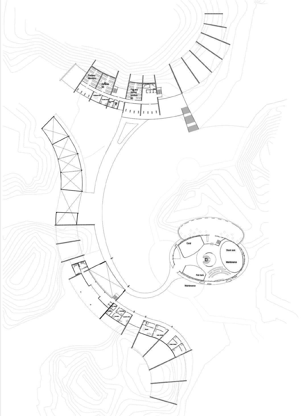
Fig 23: Masterplan of Oceanographic Research Center
Academic Section Oceanographic Collection Wet Lab Ocean Interpretation Administration Dry Lab
Fig 24: Functional arrangement
PROJECT 1 OCEANOGRAPHIC RESEARCH CENTER
PC 5.2: Resolution of project design addressing all building occupancy and functional aspects including spatial requirements and relationships and circulation aspects.
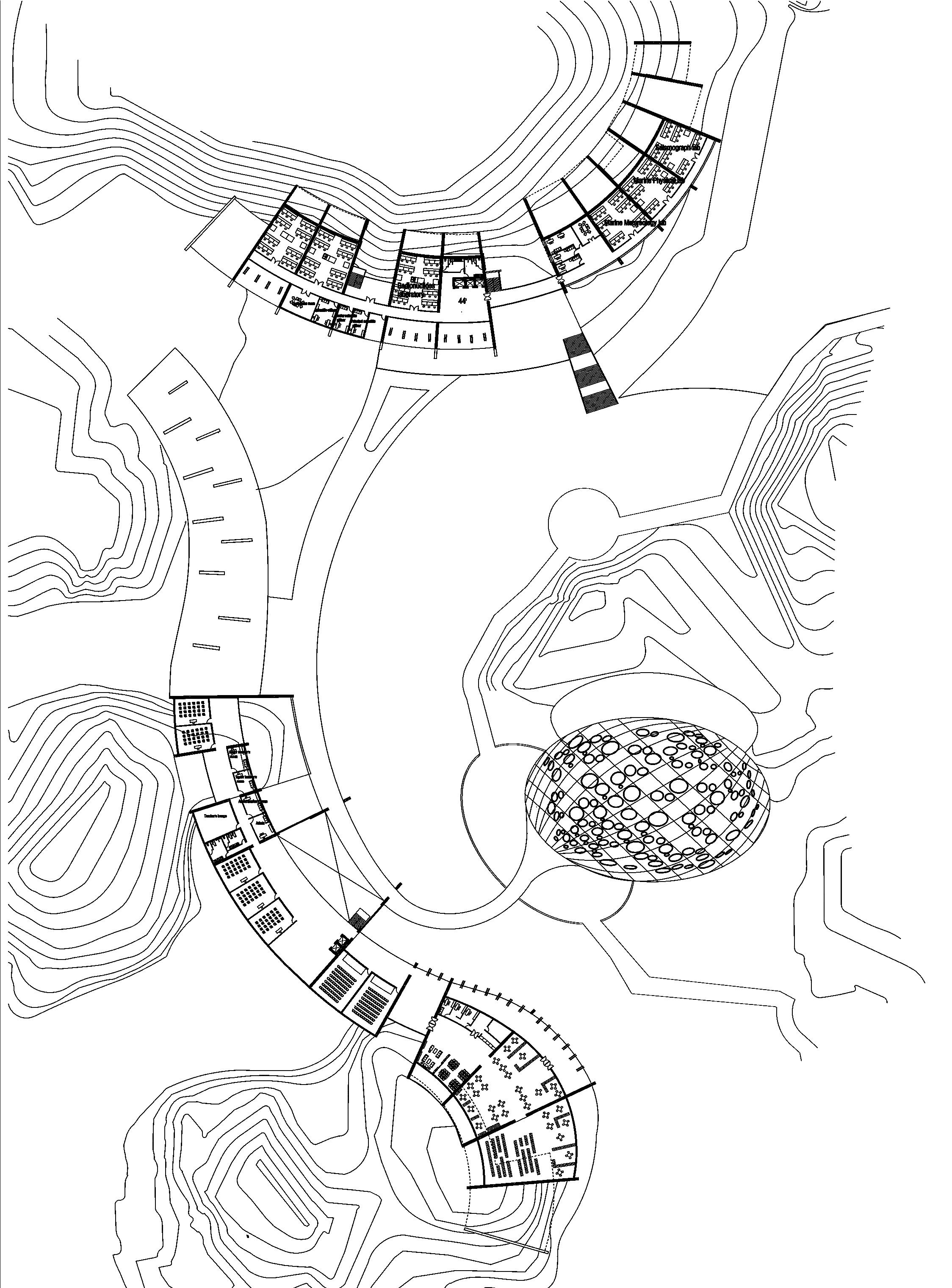
Floor plans at different levels indicate building occupancy and fuctional requirements (Fig25-Fig29)
14
Fig 25: Plan at Level 20’
15
Fig 26: Plan at Level 32’
Fig 27: Plan at Level 44’
Fig 29: Plan at Level 56’
PROJECT 2 DESIGN OF A COMMERCIAL HIGHRISE BUILDING AT HATIRJHEEL
Studio Project ( 3rd year)
Bachelor of Architecture
Location: Hatirjheel, Tejgoan, Dhaka, Bangladesh
Time period : March-May, 2010
Individual project

BACKGROUND

Trying to build taller and higher is the story of mankind. The desire to touch the sky is reflected by the pyr-amids of egyptian civilization, the ever inspiring gothic churches, and the very recent chicago high rise buildings at the end of the 10th century In every era, new invention in the construction system has extended the limit of tall buildings to a greater height. However, highrise is a solution or a problem is a debateable issue but a studio exercise on the tall building will not be futile for a highly dense city like dhaka.
A studio project was introduced in 3rd year of Bachelor of Architecture to design a commercial high rise building on a site within a newlyproposed development zone, Hatirjheel Project.
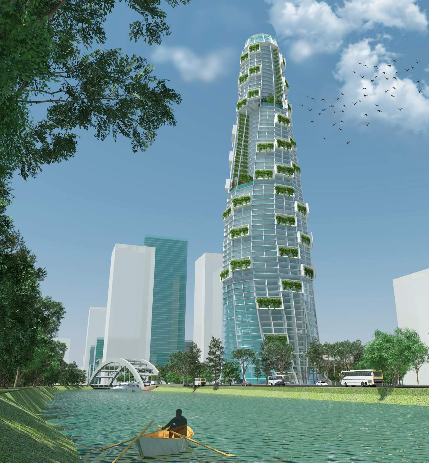
DESIGN CONCEPT
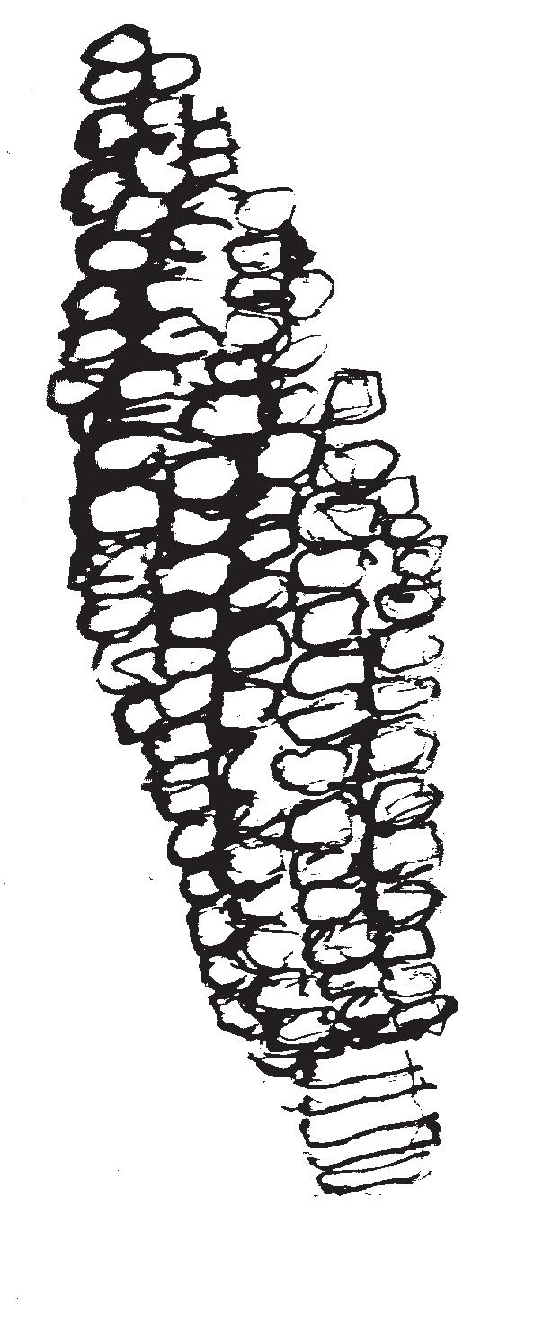
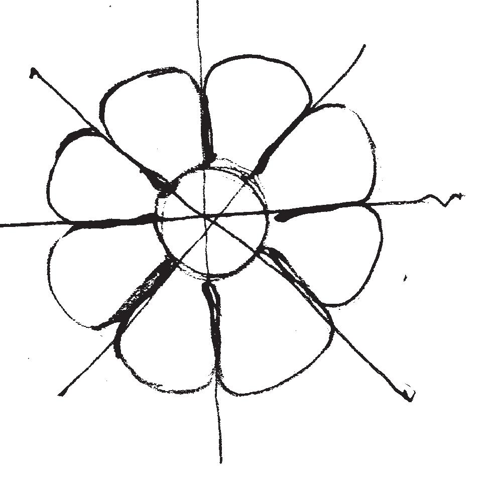

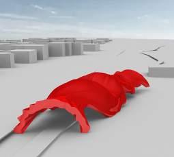
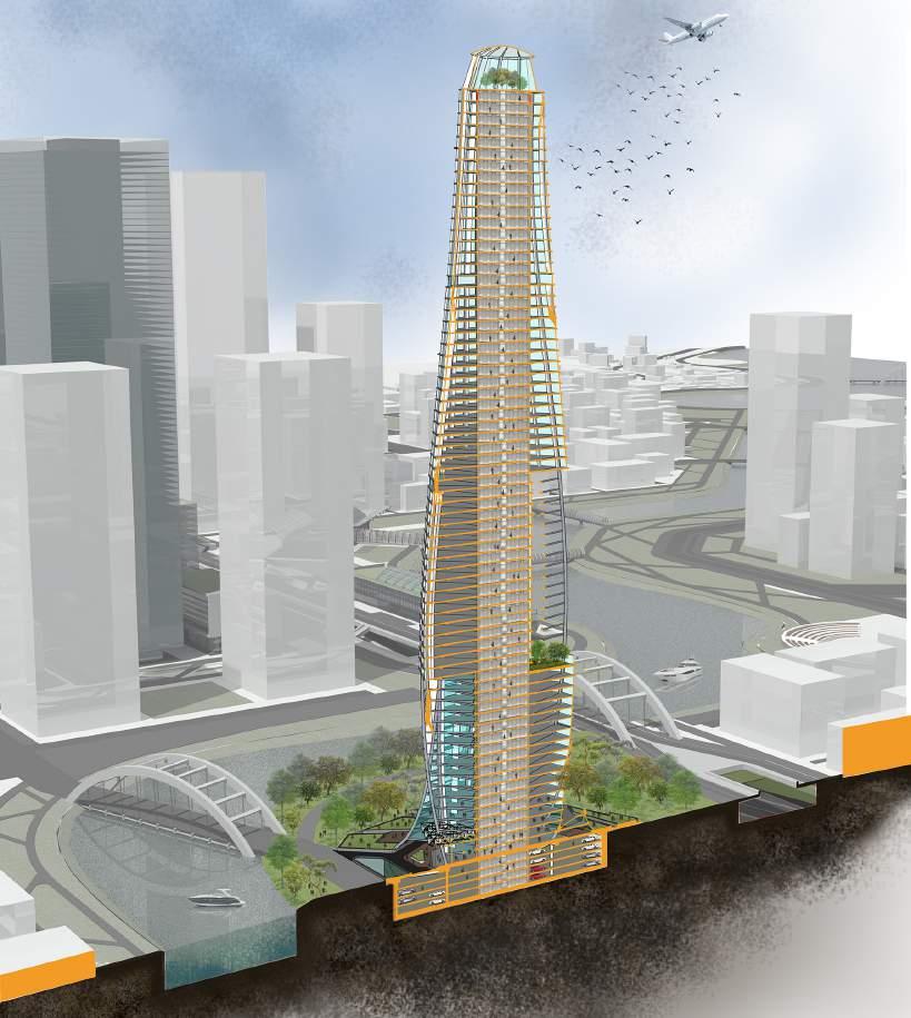
The major idea is to design an iconic skyscraper that represents a new development in the Hatirjheel area. The magnificient structure will emerge as a commercial hub with integrated community spaces. It will encorporate public parks, restaurants, movie theatres and other communal amenities with a skydeck crowning the top. The structure of the skyscraper is inspired by the natural form of corn. The central core and spiral columns tie up together with connecting beams to form the skeleton mimicking spiral arrangements of seeds in corn (Fig 30).
17
Spiral arrangement of seeds Spiral columns Seed Central layer Screen holding seeds Green space Functional space Core Circulation
Fig30: Concept diagram for design development
PROJECT 2 DESIGN OF A COMMERCIAL HIGHRISE BUILDING AT HATIRJHEEL
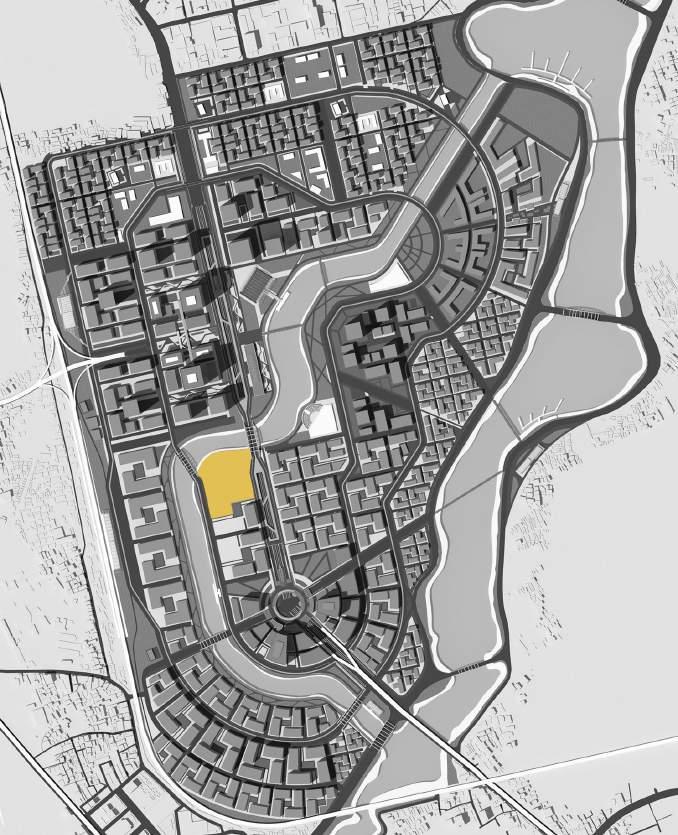
PC 2.1 : Identification, analysis and integration of information relevant to siting of project
Hatirjheel development project is an initiative to transform a neglected swamp area to a revitalized lake surrounded by recreational public open space, busy commercial strip and well configured residential areas. The area was covered with illegal slums and the water body was filled up in places to develop high-value properties without any authorization. The government adopted a holistic redevelopment approach towards the Hatirjheel project - reconfiguring land within an existing urban fabric, adding value to them by developing infrastructure, revitalizing water-body to facilitate water transport contributing much in reducing city ’s everlasting traffic congestion. The task for the studio project was to develop the design of a commercial high rise building on a suitable site located in the Hatirjheel development zone. The site (Fig:31a)was chosen mostly considering the following reasons:
• There were two proposed bridges in front of the site that increase accessibility and mobility.
• A proposal of landing platform was adjacent to the site facilitating access through the waterway
• The land was located at the bank of the lake offering a pleasing aesthetic view.
PC 3.3: Design Response incorporates assessment of the physical location and relevant wider regional , contexual and environmental issues
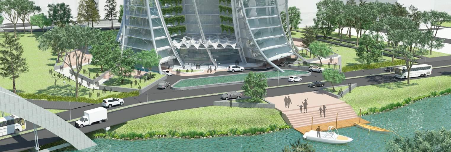
• Community facilities ( park, restaurant and movie theatre) were provided in the first three levels to address the need of local residents in harmony with the overall scheme of the Hatirjheel project to promote public activity.
• A skydeck was proposed on the top level of the building offering a spectacular waterfront view of Hatirjheel that attracts tourists and visitors.
• The ground level opened up to a public plaza, adorned with plants and trees and soothing waterbody at the front welcoming public activity (Fig31b).
• The parking was placed underground to increase soakable green spaces.
• Vertical “ Green Boxes” were added to the facade and “Green pockets” were introduced as escape pods for regular office users. Introduc ing parks and green spaces also contribute to the city’s ongoing movement of minimization of pollution and C02 emission.
• The graceful, spiral form was designed as a landmark for the community. The omnidirectional character of the form allows a pleasing view of the surrounding lakefront from all the functional spaces inside.
18
Fig31a: Location of the site
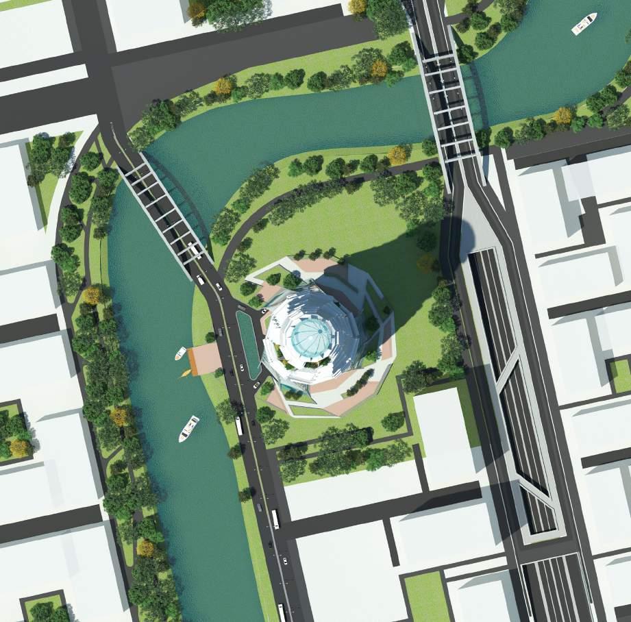
Fig31c: Site plan with surroundings
Fig 31b: connectivity of the building to surrounding context
PROJECT 2 DESIGN OF A COMMERCIAL HIGHRISE BUILDING AT HATIRJHEEL
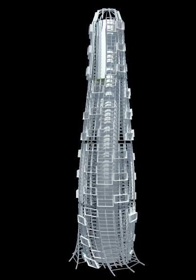
PC3.5: Exploration and application of ordering, sequencing and modelling of three-dimensional form and spatial content.
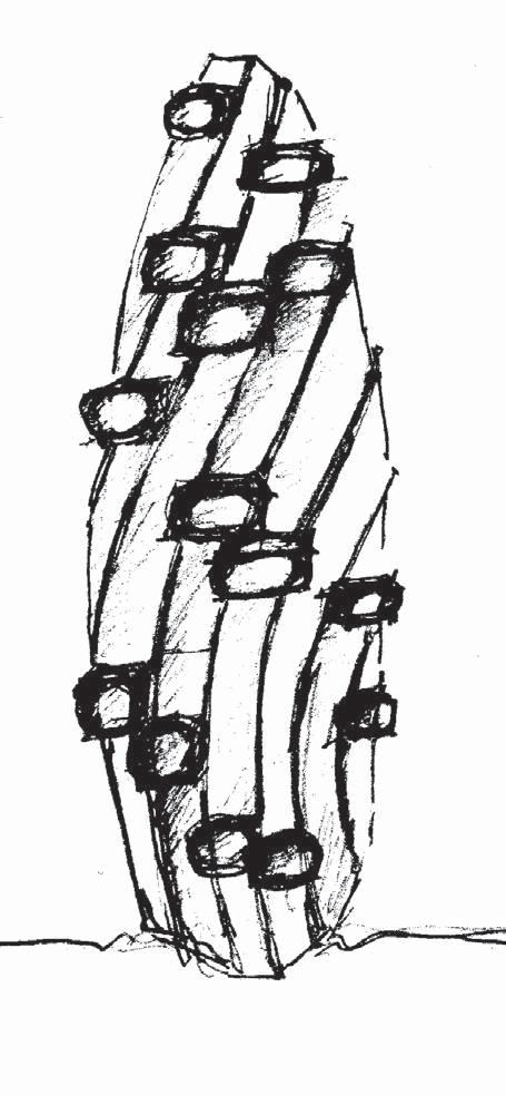
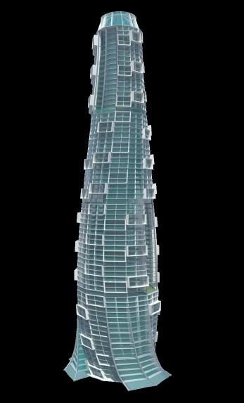
The form of the highrise building was inspired by the internal core and spiral arrangement of seeds in corn. The lower part of the tower is spreaded to accomodate more public functions and ensuring accesibility and openness towards the landscape. The upper part reduces gradually diminishing at the skydeck on top most-ly encorporating more private and commercial functions. Some void spaces in between floors were introduced to add spatial relief and create coherent solid-void relationship.”Green Box “s were added all over the building facade to create a soothing and refreshing environment for the users, also forming a dynamic pattern reflecting the lavish green landscape. The skydeck at the top grace-fully defines the termination of the form. (Fig32)
19
Fig32: Formal expresssion of highrise building
PROJECT 2 DESIGN OF A COMMERCIAL HIGHRISE BUILDING AT HATIRJHEEL
PC 3.4: Design response incorporates assesment relevant legislation, codes and industry standards
Fig 33 shows BNBC ( Bangladesh National Building Code) direction regarding FAR, building height, set back and open space relationship that was followed in the project.
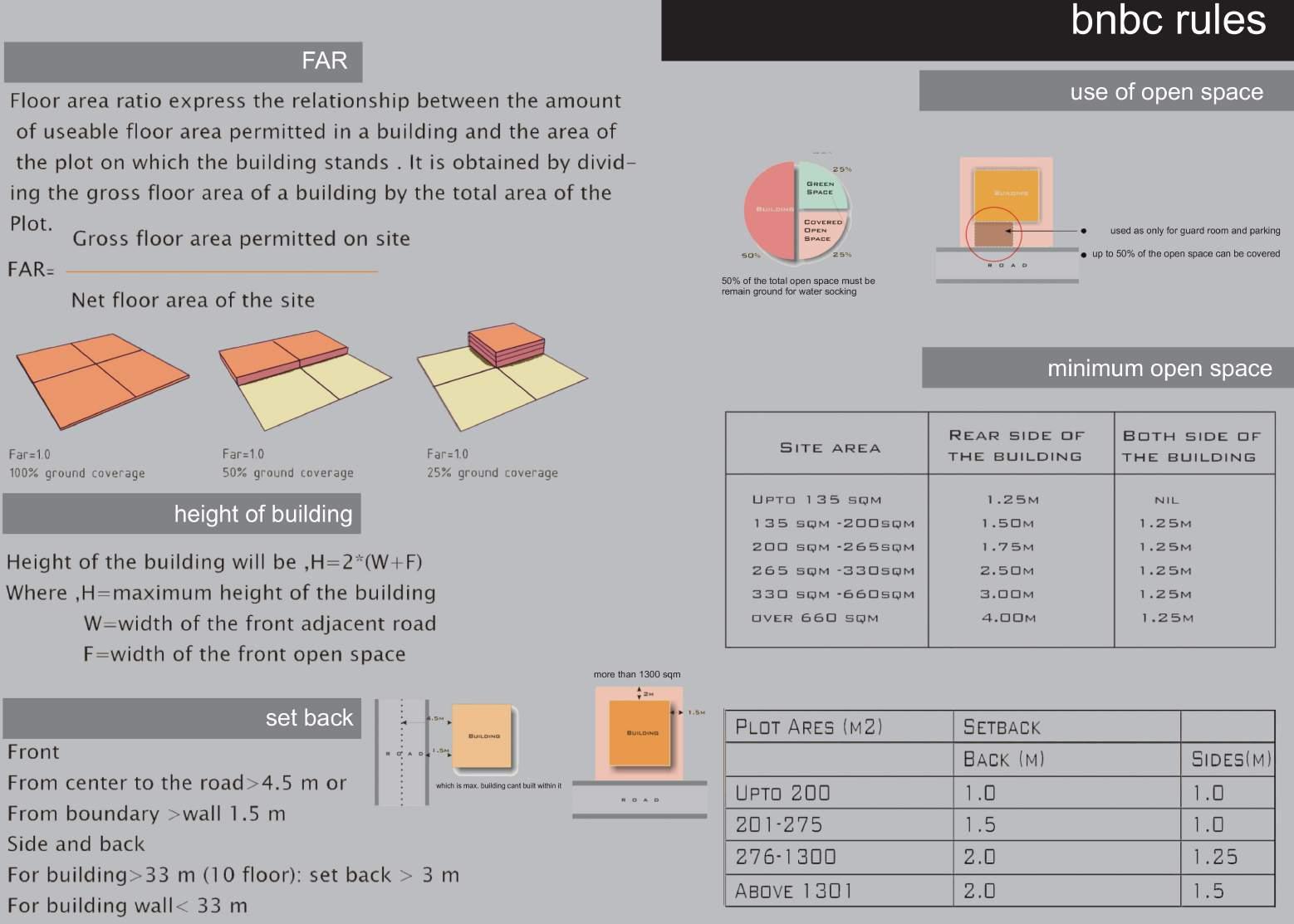
Fig 34 shows the ground floor plan including site surrounding and the chart shows the calculation of building aspects like floor area, ground coverage, etc. Building occupancy is type F1 (Commercial Office Space) and entry road is 16 M wide. The FAR value specified for F1 type building and 16M road is 9.5. The total allowable floor area and area of sin-gle floorwas determined from the FAR calculation.
Maximum Ground Coverage, Additional Ground Coverage and Mandatory Green Area was calculated and followed as per BNBC
20
Fig33: Study of BNBC rules
PROJECT 2 DESIGN OF A COMMERCIAL HIGHRISE BUILDING AT HATIRJHEEL
Project Analysis
PROPOSED
1
Design Criteria
21
COMMERCIAL HIGH RISE BUILDING
LOCATION Plot
Hatirjheel
BUILDING OCCUPANCY TYPE F1 (Commercial Office Space)
LAND AREA 13723.74 sqm
ROAD WIDTH ON THE WEST Existing road=16M 5 BASIC F.A.R FOR 16M WIDE ROAD AND >1340.00 sq.m LAND 9.5 6 F.A.R (Floor Area Ratio) Total Floor Area = Land Area 7 TOTAL FLOOR AREA 9.5x 13723.74 = 130375.53 8 NUMBER OF PROPOSED STORIES 65 9 AVERAGE FLOOR AREA 130375.53 / 65 = 2005.78
No. 55,
Link road, Rampura, Dhaka 2
3
4
Allowable Value Proposed Value 1 AVERAGE FLOOR AREA 2005.78m2 2264.2 m2 2 MAXIMUM GROUND COVERAGE 6861.76 m2 (50% of net land) 4172.5m2 (30.5% of Land Area) 3 ADDITIONAL GROUND COVERAGE parking, driveway and paved area. 3,430.88 m2 (25% of net land) 3061m2 (22.3% of Land Area) 4 MANDATORY GREEN AREA 3,430.88 m2 (25% of net land) 6,490.24 m2 (47.29% of Land Area)
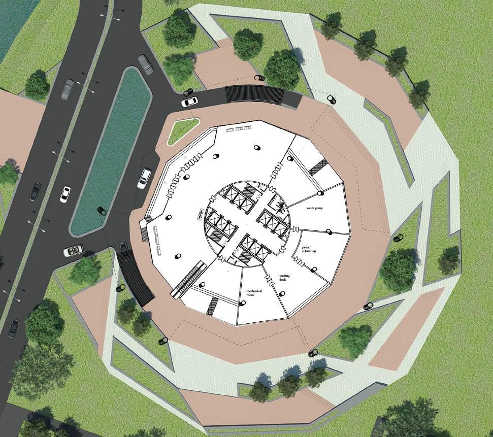
Mechanical room Loading dock Power substation Water pump
Fig34: Ground floor plan showing surroundings
PROJECT 2 DESIGN OF A COMMERCIAL HIGHRISE BUILDING AT HATIRJHEEL
PC 5.2: Resolution of project design addressing all building occupancy and functional aspects including spatial requirements and relationships and circulation aspects.
22
Fig 35: Ground floor plan
LOUNGE COFFEE CORNER SOUVENIR SHOP coffee corner lounge megazine corner SOUVENIR SHOP A store
Fig 35 shows ground floor plan including site entry and driveway. Fig 36a shows detailed plan of public amenities. Fig 36b presents a layout for typical office floors. Fig 36c presents provision of parking layout in basements.
Fig 36b: Typical Office Floor Plan
Fig 36c: Basement Floor Plan
Fig 36a: 1st Floor Plan
PROJECT 2 DESIGN OF A COMMERCIAL HIGHRISE BUILDING AT HATIRJHEEL
PC 3.7: Assesment and integration of construction systems and materials consistent with project brief
&

PC 4.5: Investigation and integration of appropriate structural, construction,service and transport system in the project design
The form was dynamic and spectacular as the prime objective of the project was to create an iconic building. Naturally the structure was challenging, conventional concrete column-beam structure wasn’t convenient to adopt. More innova-tive approach had to be taken. In response to this thought, a combination of in-situ construction and prefabrication was considered. The concrete members were cast on the site and steel members were prefabricated and carried to the site by road.
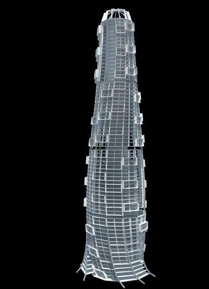
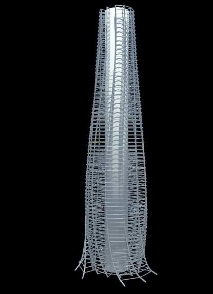
The highrise building was composed of a 4-tier basement and superstructure. The cylindrical basement with a peripheral concrete shear wall acted as a base for the superstructure. (Fig38) The concrete core was positioned at the centre of the base.12 spiral steel columns twisted around the core and connected to the core with steel beams forming the outer skel-eton. The spiral frames were integrated into the skeleton to provide support for the outer skin. The entire skeleton was covered with an outer glass skin. The Green Boxes were inserted into few places within the spiral frames to provide al-coves for plantation.
23
Core Spiral columns Beams Green boxes Glass Frames Floor slabs Exterior glass skin
1 2 3 4 5
Fig 38: Sectional perspective showing structural system
4
1 Skydeck 2 Office space
3
Green space
Public amenities
5
Basement parking
Fig37: Structural system composed of core and spiral columns
PROJECT 4
Professional project
2-STORIED FAMILY RESIDENCE AT MUKUNDA MADHUSUDANPUR
Location: Kaliganj,Satkhira, Khulna, Bangladesh
Time period : Oct2013- Jan2015
BACKGROUND
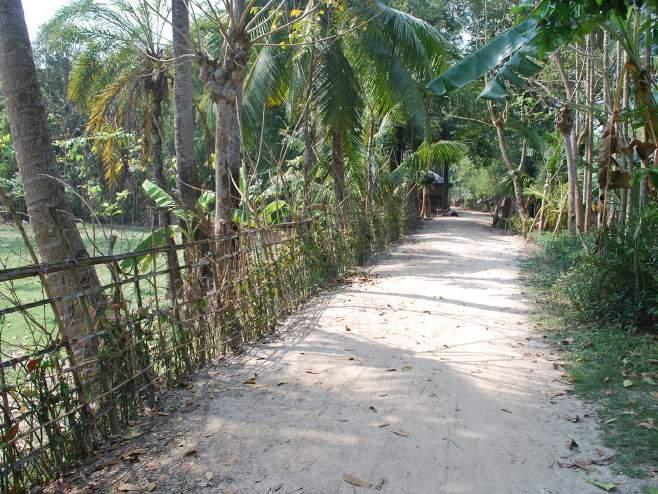
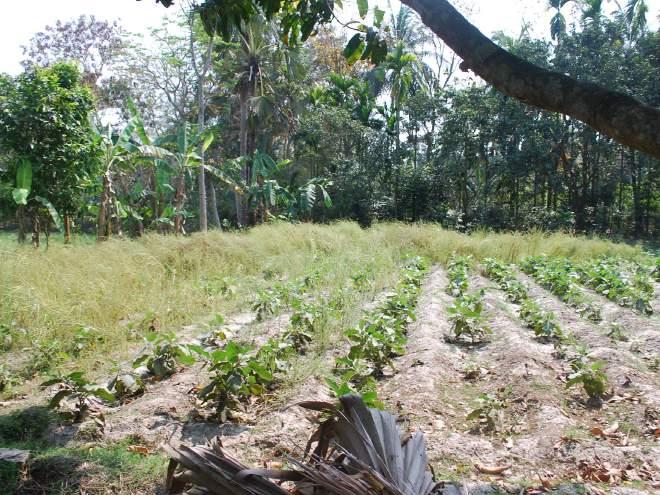
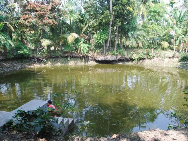
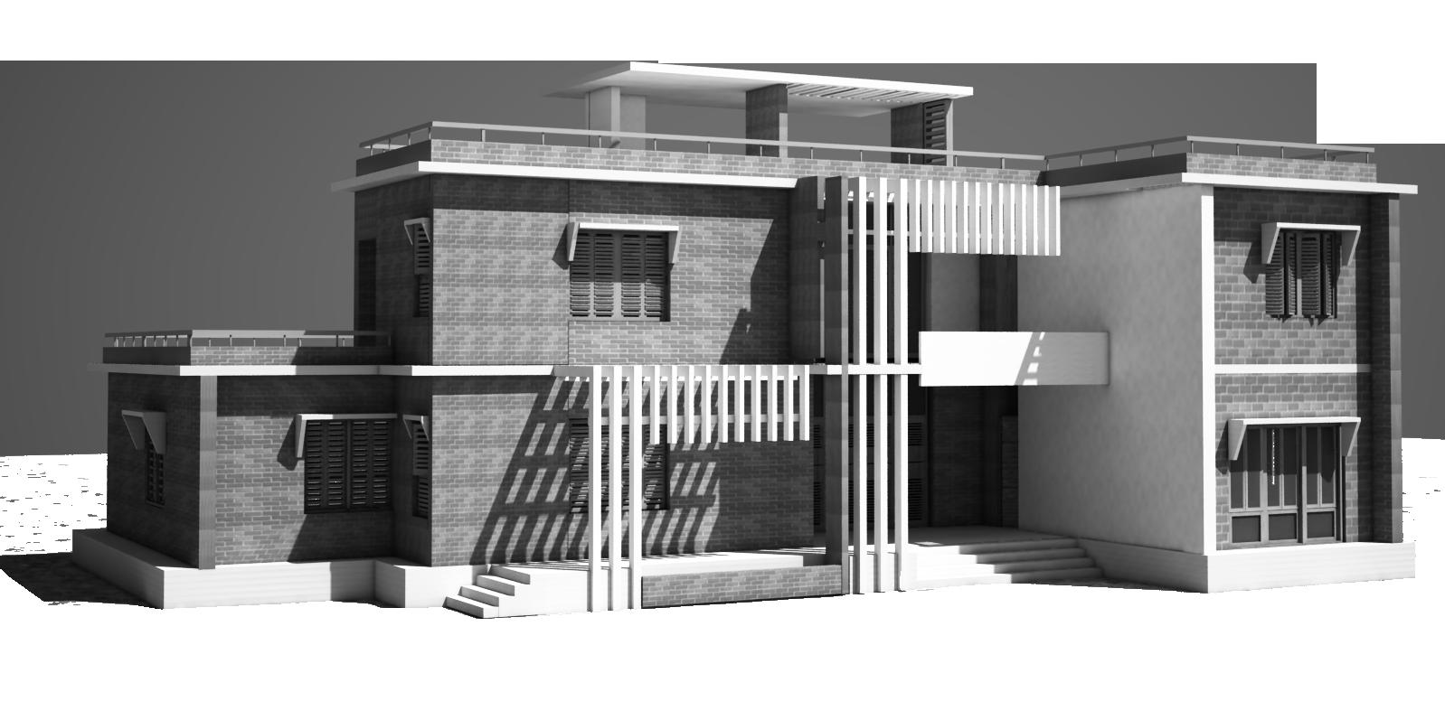
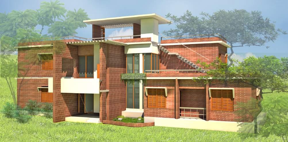
The project was set on a backdrop of the rural landscape in the southern part of the country. Fisheries and agriculture were two most prominant occupation here emphasizing on shrimp culture and trade. The client’s primary occupation was trade related to fisheries. He was living with his family in a single storey residence for a few years. Condition of the house was deteriorat-ing in time. Rather than renovating the old house, he preferred to build a new residence and move in there. He owned some lands including agricultural fields and a small pond adjacent to the existing house. He wanted to transform the place into a livable, comfortable habitat with lavish green plantation and calm, soothing waterbody.
The client planned to build a two storied house constructing in 2 phases due to budget constraints. The ground floor and surrounding landscape were to be completed in the 1st phase. Once the adequate budg-et is collected, the construction of the 2nd floor would start. His family members included his wife and three daughters. The older daughters moved out for study and work, but they still came to stay for holidays from time to time. He planned to live on the ground floor with his wife and younger daughter while making pro-vision for the other daughters on the upper floor.
The client wished to create a comfortable, aesthetically appealing home that would function in harmony with their lfestyle and practices.
35
Fig54: Site surroundings
PROJECT 4 2-STORIED FAMILY RESIDENCE AT MUKUNDA MADHUSUDANPUR
Technical & Financial Proposal for
PC1.1: Preparation & endorsement of an agreement between client and Architect. This agreement will clearly communicate terms, services to be provided and fees appropriate for the scale and type of project
The client approached the architect for the architectural and structural design of the residence. He had plans to appoint local builders and technicians to execute construction. It was established that the architect will provide a set of drawings including architectural, structural and construction drawings and approval sheets as per building code for Union Pari-shad approval. The structural design will be subcontracted by the architect to a suitable consultant.FIg 55 shows the agree-ment between the architect and the client outlining the scope of services and appropiate fees for different stages of the project.
PC1.5: Knowledge of different procurement processes available and evaluation of the impact these have on the project.
The probable procurement options for the project were Lumpsump contract, cost plus contract or design and construct. The client mentioned there was a budget constraint- so his plan was to execute the project in twophase. The first phase was to construct 1st storey of the building and start residing with his family. After The second storey would be built in the second phase after an adequate budget is accumulated. Cost plus option was discarded as the actual cost of construction couldn’t be determined due to an uncertain timeframe. The client had his own team of builders and technichians so design and contruct contrat was off the table. He was eager to acquire the set of design drawings, approval sheets for 2- storey building and start construction of 1st phase. Considering the scenario it seemed logical to set up a lumpsump contract for different stages of design development and 1st phase construction.
PREPARATION OF DETAILED DESIGN OF A RESIDENCE, APPROVAL SHEET AND CONSTRUCTION DRAWINGS AND SELECTION OF DIFFERENT VENDORS FOR SUPPLY AND CONSTRUCTION AS PER 200 SQM SITE OF ABDUL MAJID AT MUKUNDA MADHUSUDANPUR, KALIGANJ,SHATKHIRA
A. SCOPE OF SERVICES
The consulting services to be provided by the consultant are as below:
Program analysis and design of interior and exterior space layout with Furniture and Fixture
Recommendation of floor, walls, Ceiling with types and colors of Materials respecting environmental issues
Required Structural solution to incorporate all the facilities and services
3-d computer modeling, visualization and BOQ preparation.
Top Supervision of Works on site by Architects & Engineers.
Selection of different vendors related with all infrastructure.
B. OUTPUTS
Outputs to be supplied by the consultant are as below:
a) Architectural drawings
b) Approval sheet for Union Parishad as per BNBC.
c) Detail engineering design and construction drawing
d) Progress report
e) Completion report
C. FEES , TIME SCHEDULE AND MODE OF PAYMENT
Total time to be required for the design and other drawing related services is 90 days from receiving work order/signing the contract agreement. The item-wise time to be required is presented below:
4.
5. Revision & Checking of Construction Documents and Tender document
6.
7. Each bill checking and payment certified
Bill checking time will be 10 days after submission of each bill by vendors.
FOR THE CLIENT FOR THE CONSULTANT
36
Mukunda madhusudanpur , Kaligonj, Satkhira Lecturer, South East University Sl. No. Installment Time Schedule Fees Payment Conditions 1. Pre-Design Services for Development Plan Within 15 days after contract agreement 20,000 BDT At the time of contract agreement/ work order 2. Schematic Design within 30 days from predesign submission. 30,000 BDT after submission of Pre-Design Services for Development Plan
Design development within 15 days from schematic-design
50,000
Abdul Majid Awnili Shabnam
3.
submission
BDT after submission of Schematic Design
100,000
Construction Documents within 15 days from DD submission
BDT after submission of Design development
within
50,000
15 days from CD submission
BDT after submission of Construction Documents
50,000
Supervision of Works 5 times during construction
BDT after submission of Revision & Checking of Construction Documents and Tender document
Fig 55: Agreement between Architect and Client
PROJECT 4 2-STORIED FAMILY RESIDENCE AT MUKUNDA MADHUSUDANPUR
PC 1.7: Preparation of project brief for approval by client and relevant stakeholders.
The project brief was determined through verbal discussion with the client, there wasn’t any formal document. The initial considerations were sketched and noted down as in Fig 56&57. The site was covered with local trees and vegetation. The client’s idea was to cut down most of the trees to accomodate new construction. The architect proposed to configure the functions considering the position of trees so that there is minimum removal.
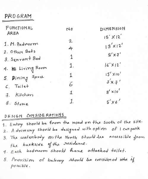
The client agreed on the proposal. He also had some specific requirements regarding functional spaces and their di-mensions (Fig56). Servant bed and kitchen storage were to be provided attached to the kitchen. Bedrooms should be spacious and each of them should have attached the toilet. The house should be as open as possible including balconies and terraces.
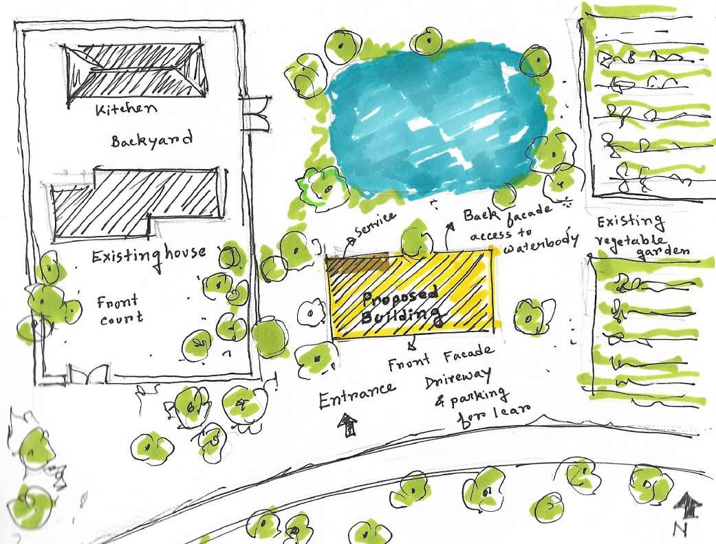
PC 2.2 : Application of priciples controlling planning,development and design for the project site
The client had 10,243.18sqm property including existing house, Agricultural fieldsand water body He ex-pressed interest in building the new residence in his property but wasent sure about the location or area of the site for new construction. After analizing, his requirements about the 500 sqm area were allocated and proposed by the architect for site development.
The following principles were followed in the process of site planning and development and design:
1. The existing building was located on comperatively high land and compact soil. The land near the house was selected for new buildings considering ease of construction and reduction in the cost of earth filling for site development.
2. The agricultural field on the east side was low land and soil was loose, not suitable for construction. The architect also emphasized on preservaing the agricultural fields as it is considering its environmental and economic value.
3. The site was proposed near the existing road just living space for driveway and parking considering the ease of service and utility management.
4. Considering the cultural context of waterbody being an integral part of daily life, the site was placed ad-jasent to the waterbody on North.
5. The site sloped away from the road towards the bank of the waterbody. The plinth height was proposed 3.5’ to protect the house from a flood.
37
Fig 56: Site plan
Fig 57: Sketch outline of project brief
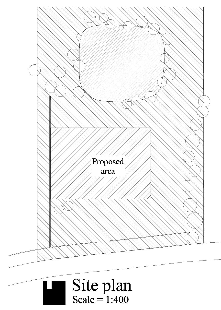
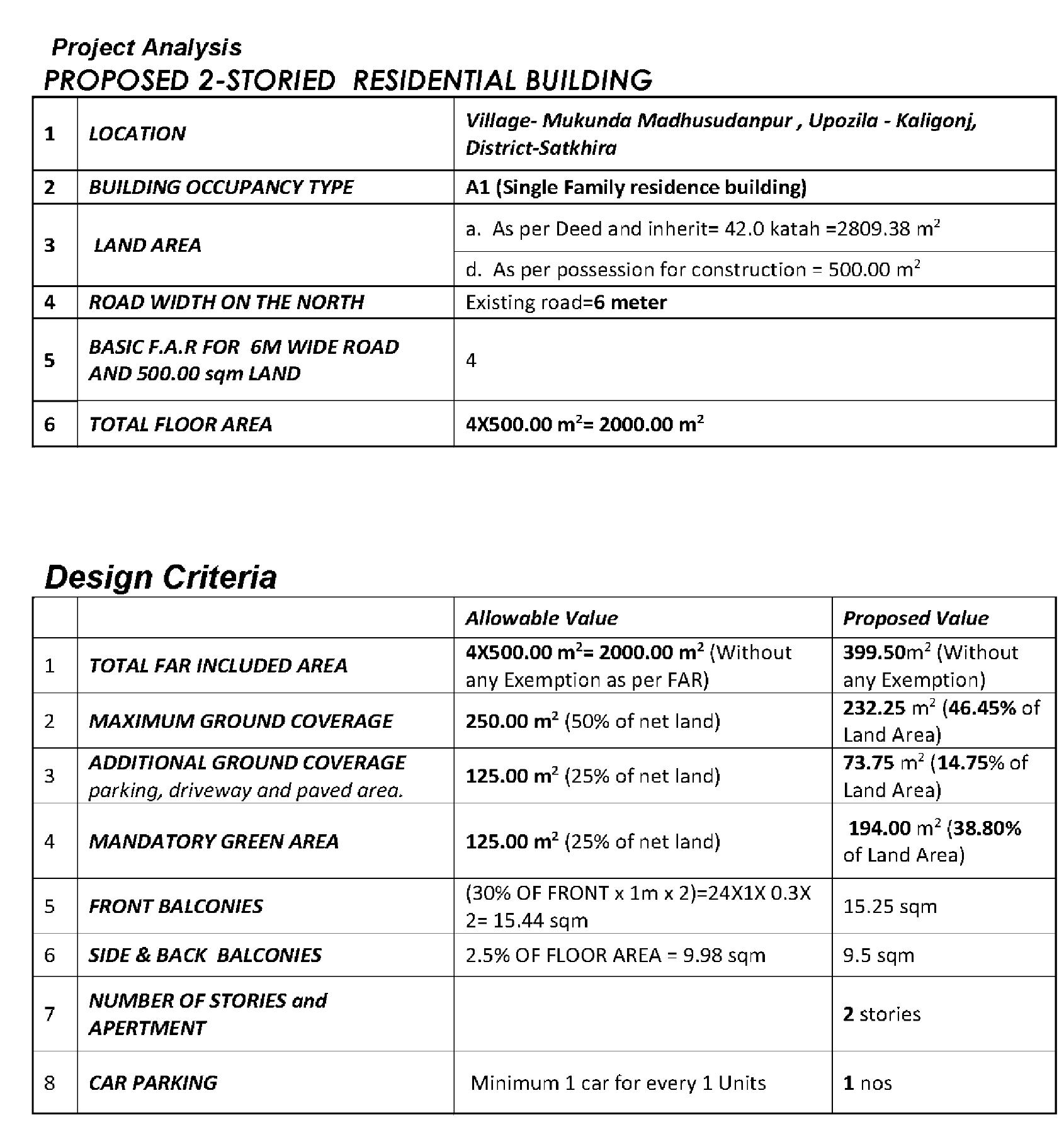
PC 3.4: Design response incorporates assesment relevant legislation ,codes and industry standards
PROJECT 4 2-STORIED FAMILY RESIDENCE AT MUKUNDA MADHUSUDANPUR &
PC 5.3: Evaluation and integration of regulatory requirements.
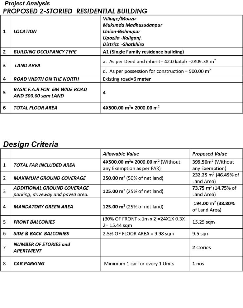
The design of the building had to complie with the BNBC code (Bangladesh National Building Code). As mentioned in the chart the building occupancy type is A1( single family residence). Allocated land area for construction is 500 sqm. The existing entry road is 6m wide.F.A.R (Floor Area Ratio) for 6m road and 500 sqm is 4.Total calculated floor area is around 2000sm.(F.A.R=Total Land Area/Total Floor Area). Pro-posed land area is around 400sqm which is within the limit.
The chart shows maximum ground coverage is 46.45% ( 50% allowable) and additional ground coverage is 14.75% (25% allowable) of land area which complied with the regulation. Proposed green area (38.8%)is more than the mandatory green space speciefied in the regulation(25%).
38 Site plan M bed 13'x16' Bed 12'x15' Guest bed 12'x14' LIVING 13'x15' Dining 15'x19' Foyer Kitchen 7.5'x10' Kit.store Servent Bed7'x8' Water body
Fig 58: Site plan showing the plot area
PROJECT 4
2-STORIED FAMILY RESIDENCE AT MUKUNDA MADHUSUDANPUR
PC 4.1: Evaluation of design options in relation to project requirements
The physical form and layout plans were subjected to continuous change and modification in response to changing briefs. Initially, the client wanted to have 2 bedrooms and 2 toilets ( 1 common,1attached to masterbed)on the ground floor level. Option 1 was developed considering these criteria(Fig59a). Later the client wished to add another guest bedroom with an attached toilet. Option 2 was developed in response to that change of requirement(Fig59b). The plan layout was more open to nature, creating access to adjacent kichen garden on the east. A small waterbody was created to achieve a soothing environment to the patio opening to-wards the backyard.
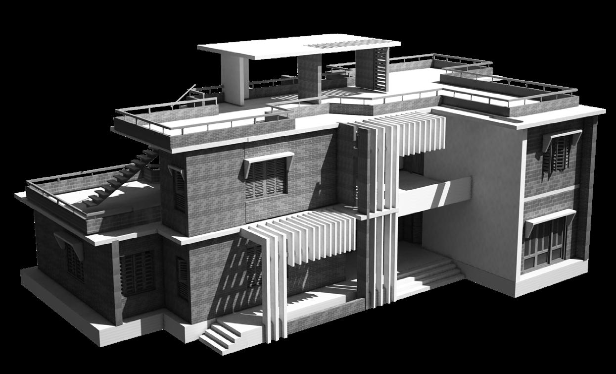
Fig 60a-60d shows chronological development of physical form in response to the project require-ment.Option1 had an open terrace in the front and only 2 bedrooms on the ground floor. After that, there were gradual development and options considering many facts like the addition of more beds and toilet on the ground floor, reposition of the open terrace on the north side due to climatic consideration, integrating shading devices and louvres, change in stair location etc.
39
LIVING M bed Dining Kitchen Kit.store Servent Bed Guest bed Ground floor plan M bed 13'x16' Bed 12'x15' Guest bed 12'x14' LIVING 13'x15' Dining 15'x19' Foyer Kitchen 7.5'x10' Kit.store Servent Bed7'x8' Water body Ground floor plan
Fig 59a: Ground floor plan, Option 1
Fig 59b: Ground floor plan, Option 2
Fig 60a: Generation of form Option 1
Fig 60b: Generation of form Option 2
Fig 60c: Generation of form Option 3
Fig 60d: Generation of form Option 4
PROJECT 4 2-STORIED FAMILY RESIDENCE AT MUKUNDA MADHUSUDANPUR
PC
4.2 :Evaluation
of design options against values of physical, environmental and cultural contexts.
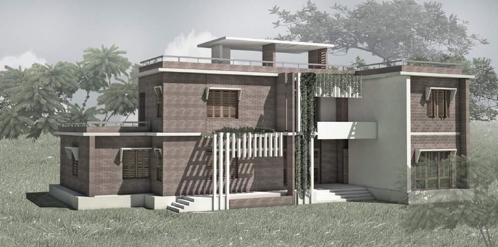
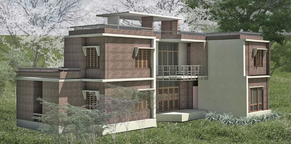
One of the primary focus of the design was to build a house that naturally blended well with its surroundings and en-sured the health and well being of the occupants. Option1 had an open balcony with patterned railings made of mild steel(Fig 61a). The entry was on the south side, sub-jected to overexposure to sunlight. The facade demanded more shade and protection to ensure thermal comfort. There was also an issue of privacy. The client wanted the upper floor to be more intimate and private family space, less visible from outside if possible. Option 2 was developed considering sun protection and privacy (fig61b). An open balcony was created along the front facade of the building to create a buffer zone before entering the functional spaces. The space was fitted with fixed lou-vres that continued overhead to form the roof. The space was able to cut off the sun and provide a cooler environment. Creepers were planted along the louvres to create a soothing environment. The space was perfect for spending after-noon tea-time with family. The railing of the 1st floor balcony was transformed into a solid wall and louvres also dropped down from the roof to provide shade and privacy to the occupants.
PC 4.7: Coordination and integration of appropriate environmental systems, including for thermal comfort, lighting and acoustics.
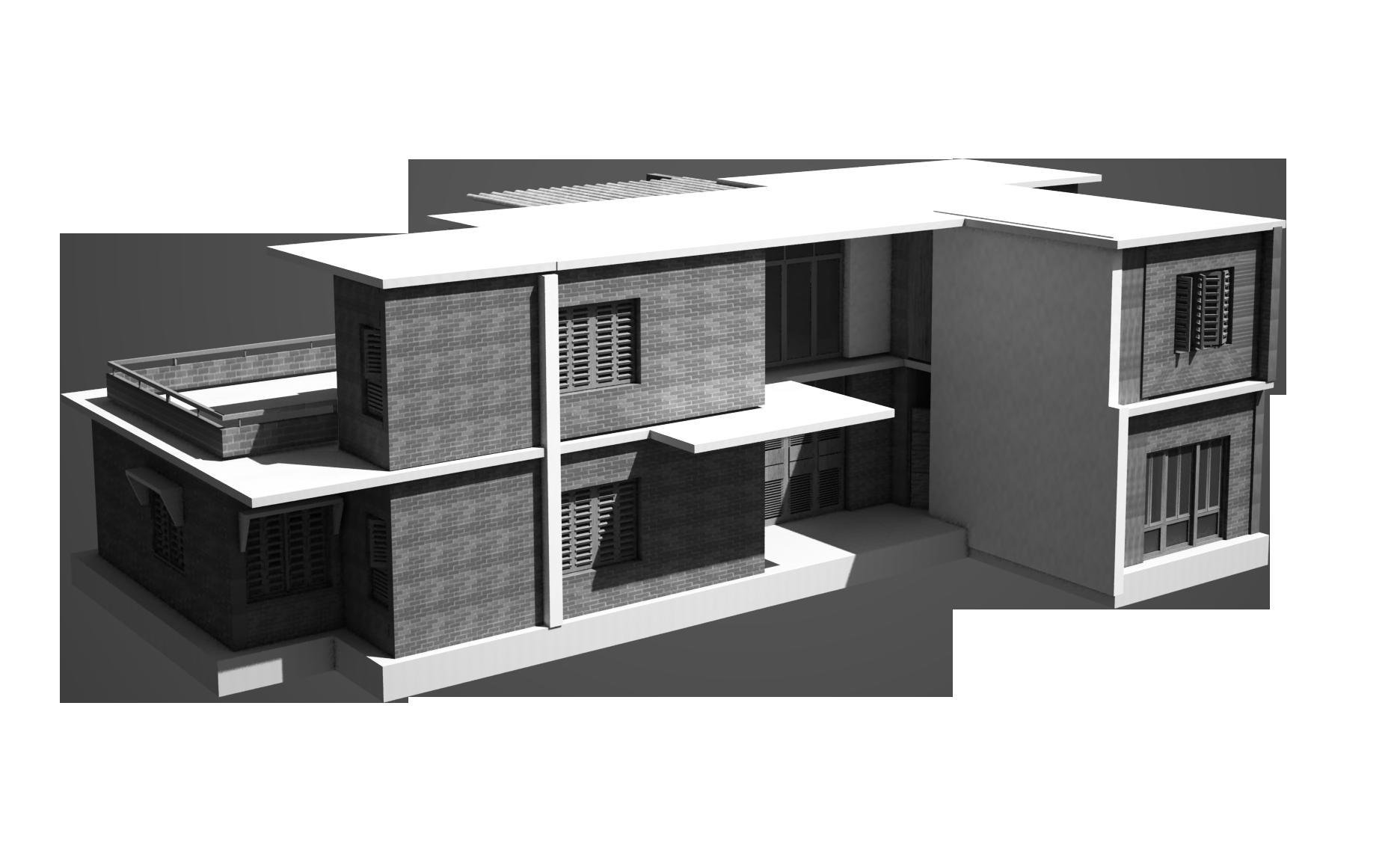
Appropriate environmental systemsincluding thermal comfort, lighting and weather protection was incorporated in the design(Fig 62):
• The bulding was north-south oriented to allow adequate cross ventilation. Cross ventilation is essential to ensure thermal comfort as the climate is humid.
• The bedrooms had adequate no of openings to allow the breeze to pass through, at least two or three if possible
• The windows were made of Manogo wood, they were fitted with operable louvres. Level of ventilation can be controlled even when the windows are closed for security purposes.
• A small waterbody was created adjacent to the north facade relating to the larger waterbody on the site. Water lities were planted there to create a soothing. aesthetically pleasing environment. The waterbody contributed to keeping the temperature of the semi-open spaces low and comfortable.
• Adequate lighting was ensured by providing large openings as muxh as possible. The openings were covered with shad-ing devices inspired by tocal trends.
• A fix louvred space, planted with creepers was created at the front facade providing a shaded transitional zone. This space reduced temperature, provided shade and comfort to inner functional zones.
• Perpheral walls were 10” thick to create solid thrmal mass to prevent heat penetration and keep the interior cooler.
• Large foliage trees that already existed on the site were retained as it was and new trees were planted to provide shade and protection.
40
Fig 61a: Front facade, Option 1
Fig 61b: Front facade, Option 2
Fig 62: Building form,North side
PROJECT 4 2-STORIED FAMILY RESIDENCE AT MUKUNDA MADHUSUDANPUR
PC 7.1 Identification of available procurement methods and assessment of relevance and application to the project.
After Completing the design and drawing of the project, in this case, a private house, the next step of action was to construct the house for which the following steps are to be taken.
The bill of quantities (BOQ) of the materials and works both for structural erection and finishing items were prepared. After that, any of the following procurement methods could be adopted for the execution of the project.
i)Tender Enquiry might be floated giving all the details of the project and attaching the BOQ and seek price quotation from qualified real state contractors. On receiving the offer from prospective contractors the cli-ent then had to evaluate the price quotations on the basis of their experience and competitive price and select one contractor.
ii)Alternatively, the client could appoint an architectural consultant and engage other technicians, such as mason, rebar binder, tile worker, carpenter, plumber, etc. and procure himself all the construction materi-als and finishing items on his own choice. The construction of the house can be carried out under the super-vision of the consultant and the client himself.
The client adopted the 2nd option for the construction of his residence.
PC 8.1: Selection process for appropriately qualified contractors is in accordance with procurement method and project contract.
Architect sugested the client to appoint contractors based on their skill and worl experience to carry out this specific type of constructuon.Key considerations were:
• The house construction system was a combination of brickwotks and concrete casting.So, the contractor should have knowledge and expertise in both construction system.
• The contractor should have capabity to understand drawings and specification and sound technical knowledge to communicate construction related issues.
• They should have local experience in constructing 4/5 houses following similar type of construction.Knowledge of curing period of concrete/ brick in local atmosphere, material properties of local materials was important to understand.
• Erection of scaffolding and preparation of formwork was necessary for casting concrete in floor slabs, stairs etc.The contractor must have expertise in local madebamboo scaffolding and wooden formwork construction.
• Salinity of water was an evident issue in concrete mixing in the locality.The contractor must have knowledge and experience on how to produce concrete mixture,morter preventing contamination from saline water as much as possible.
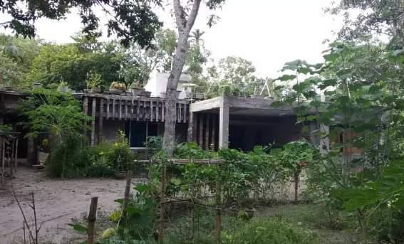
Based on this criteria, The client primarily selected 3 local contractors.Finally one contractor was choden based upon discussion between client and architect.
41
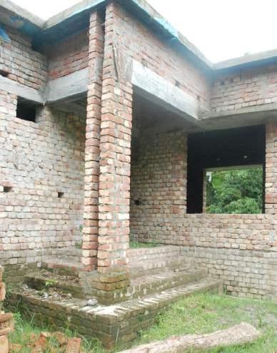
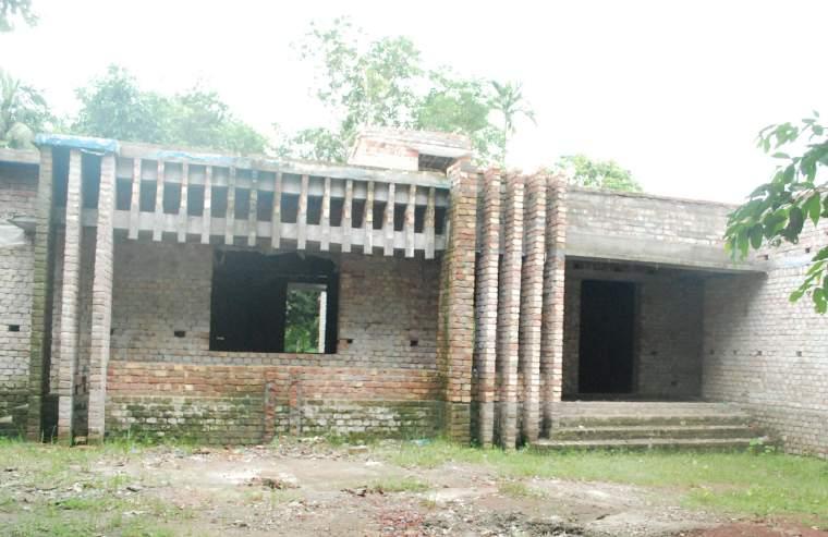
Fig 63: Initial stage of construction
Fig 64: Intermediate stage of construction
PROJECT 4 2-STORIED FAMILY RESIDENCE AT MUKUNDA MADHUSUDANPUR
PC 4.5: Investigation and integration of appropriate structural, construction, service and transport systems in the project design
The initial proposal from the architect was to construct the house following the RCC column-beam structure. After a dis-cussion with the client and local builders, the idea was discarded considering the climatic issue. The village is located in the southern corner of the country which is very close to the Bay of Bengal. The land and water are subjected to severe salinity. During concrete mixture it is very difficult to prevent salinity as even water vapour in the atmosphere is fille with salt. So, the steel reinforcement inside the column comes in contact with saline water and easily gets corrugated. Co-sidering this fact brick wall construction system was followed. Fig 65 shows working drawing for foundation layout and Fig 66 shows typical wall section and foundation detail.
42
:---------20/08/2014 Cs-025 : : 2 ABCDEFGHI 1 3 6 4 5 7 8 ABCDEFGHI 2 1 3 6 4 5 7 8
Fig 65: Foundation layout
Foundation for 3000mm wall
PROJECT 4
2-STORIED FAMILY RESIDENCE AT MUKUNDA MADHUSUDANPUR
Foundation for 6000mm wall
43
:---------20/08/2014 Cs-025 : : P.G.L. R.L. P.L. 1st layer brick laying for minimum 7 days curing 2nd layer brick laying for minimum 7 days curing Final layer brick laying for minimum 7 days curing 1st layer brick laying for minimum 7 days curing 2nd layer brick laying for minimum 7 days curing Final layer brick laying for minimum 7 days curing
P.G.L. R.L. P.L. P.G.L. R.L. P.L.
Typical wall section
Fig 66: Typical wall section and foundation detail
PROJECT 4 2-STORIED FAMILY RESIDENCE AT MUKUNDA MADHUSUDANPUR
PC 4.4: Inclusion of expertise of relevant specialists and consultants in developing the project design.
The architect was responsible for architectural and landscape design, providing architectural drawing and construction documents.Structural design was subcontructed to a thrid party consultant. Fig 67 shows a drawing of ground floor slab reinforcement that is part of drawing sets reiceived from the civil engineer. Local technicians were consulted regarding electrical design, to create a conduit layout.
PC
6.2: Continuing coordination and integration of information and project material from relevant consultants, specialists and suppliers.
Ground Floor Slab Reinforcement Details
The architect was tasked to appoint and co-ordinate relevant parties regarding design. Fig 68 shows e-mail communi-cation collecting structural drawings from the engineer.
Local technichians provided elctrical conduit layout. Architect analysed and evaluated the probable suitabiltity of con-struction materials and reported to the client. The client arranged suppliers and material collection.

44 2 A B C D E F G H I A B C D E F G H I 1 3 6 4 5 7 3 8 1 2 4 5 6 7 8
North DUCT STAIR 3'-0" 3'-0" 4'-0" 4'-0" 3'-0" 3'-0" 2'-6" 2'-6" 3'-6" 3'-6" 3'-6" 4'-3" 4'-0" 4'-0" 3'-0" 3'-0" 3'-0" 2'-6" 2'-6" 3'-0" 1'-9" 4'-0" 4'-6" 4'-0" 4'-6" 4'-6" 4'-6" 5'-0" 5'-0" T = 5" T = 5" T = 5" T = 5" T = 5" 10Ø@ 6" c/c alt. ckd 10Ø@ 5" c/c alt. ckd 10Ø@ 5" c/c alt. ckd 10Ø@ 5" c/c alt. ckd 10Ø@ 5" c/c alt. ckd 10Ø@ 5" c/c alt. ckd 10Ø@ 6" c/c alt. ckd 10Ø@ 5" c/c alt. ckd 10Ø@ 6" c/c alt. ckd 10Ø@ 6" c/c alt. ckd 10Ø@ 5" c/c alt. ckd Corner Reinforcement Corner Reinforcement Corner Reinforcement Corner Reinforcement Corner Reinforcement Corner Reinforcement Floor Beam -(10"x15") Floor Beam-1( 10"x15") Stair rebar 10Ø@ 9" c/c Top & Bot SB Beam-B1 Beam-B1 LB-1 Beam-B2 10Ø@ 6" c/c 1-10 ØExtra Top 2-10 ØExtra Top 2-10 ØExtra Top Vill. Mukunda Madhusudanpur Upozila Kaligonj District Satkhira. Drawing Title Ground Floor slab Reinforcement Detail Scale Date 03-12-2013 Sheet No. S/01 Client Abdul Majid Residential Building: H-16,R-10/A, Block-H, Banani, Dhaka-1213 2-10 ØExtra Top Design By Engr. Zahidul Islam Union Holdings Ltd The drawing copyright and the property of author and must not be changed, copied used without written permission Union Holding Ltd.
Fig 67: structural drawing received from civil engineer
Fig 68: E-mail communication regarding structural design
PROJECT 4 2-STORIED FAMILY RESIDENCE AT MUKUNDA MADHUSUDANPUR
Pc 6.4: Timely completion and communication of accurate and comprehensible documents that will include as required, drawings,models,specifications,,schedules and other relevant mode of information
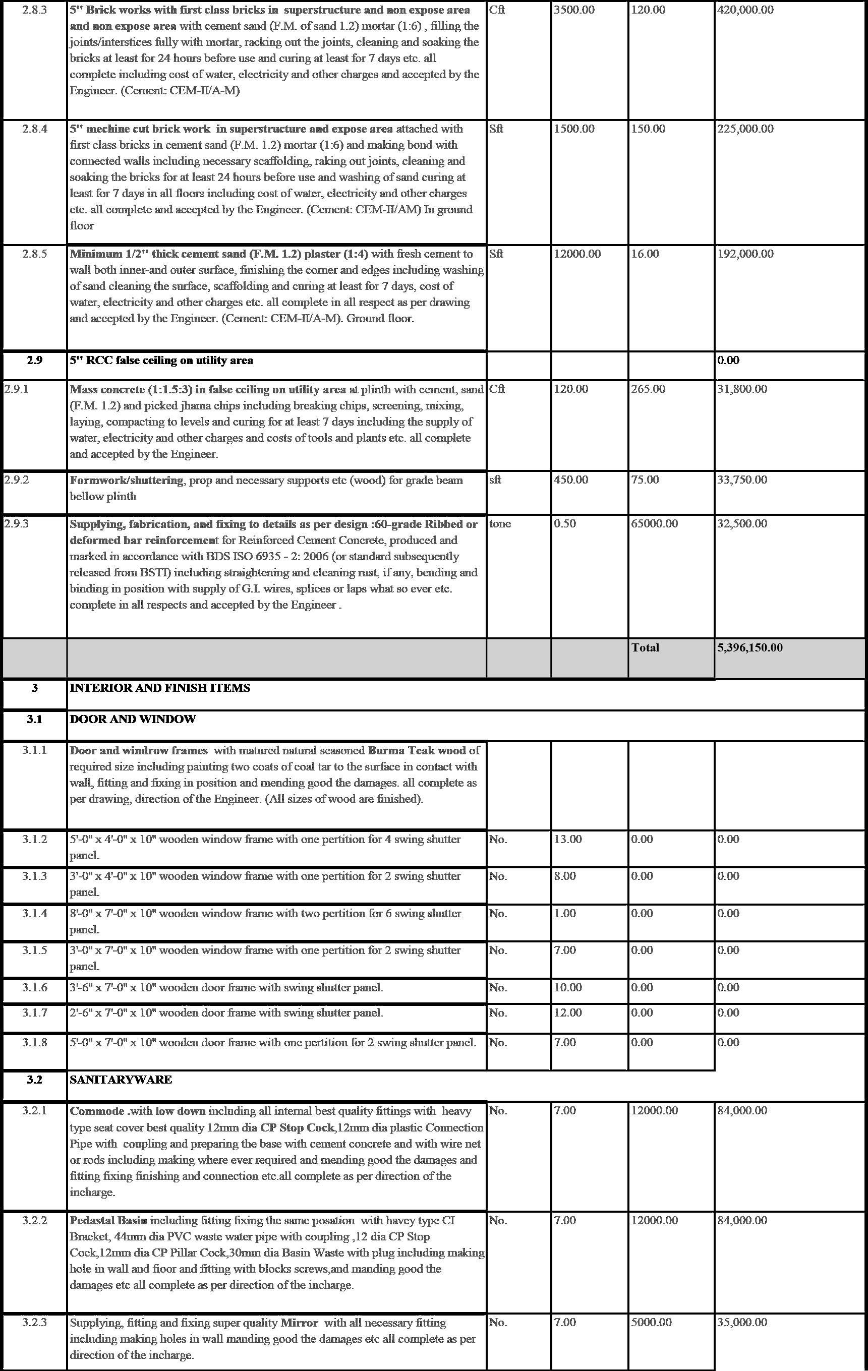
The architect provided a set of construction documents including working drawings, specifications, schedules etc. Con-struction documents included all floor plans, elevations, sections, foundation layout, and typical wall section and foun-dation details, Slab reinforces layout, stair detail, water body detais, specifications, and cost estimation, etc. The client wanted complete design and drawing for 2 storied building. The construction was to be completed in two phases.The ground floor construction was to start as soon as possible. The 1st floor construction was going to start after the accu-mulation of an adequate budget.
Fig69-71 presents architectural drawings for construction, Fig 72-73 shows structural drawings and Fig 75 shows cost estimation.
PC 9.5: Knowledge of the legal and ethical obligations relating to copyright and intellectual property requirements
The copyright of architectural documents belonged to the architect.Fig 70 shows the template declaration used in all drawings.
Fig 70: Copyright of architectural documents
45
:---------20/08/2014 Cs-025 : : Mbed " Bed 16'1"x11'9" Guest bed Living FoyerDining Kitchen Kit.store Servent Bed Water body 2 ABCDEFGHI 1 3 6 4 5 7 8 Closet Window and wall dimension Window and wall dimension ABCDEFGHI 2 1 3 6 4 5 7 8 A A Toilet Toilet Toilet Toilet
Fig 69: Working drawing- Ground Floor plan
PROJECT 4 2-STORIED FAMILY RESIDENCE AT MUKUNDA MADHUSUDANPUR
46 :---------20/08/2014 Cs-025 : : Mbed 13'x16'6" Guest bed 12'x16' Family living Bed 14'x15'6" Store Window and wall dimension Window and wall dimension A ABCDEFGHI ABCDEFGHI 2 1 3 6 4 5 7 8 2 1 3 6 4 5 7 8 A Toilet Toilet Toilet Terrace
Fig 70: Working drawing- 1st Floor plan
PROJECT 4 2-STORIED FAMILY RESIDENCE AT MUKUNDA MADHUSUDANPUR
48
2 A B C D E F G H I A B C D E F G H I 1 3 6 4 5 7 3 8 1 2 4 5 6 7 8 First Floor Slab Reinforcement Detail North 3'-0" 3'-0" 4'-0" 4'-0" 3'-0" 3'-0" 3'-6" 3'-6" 4'-3" 4'-0" 4'-0" 3'-0" 4'-6" 4'-6" 5'-0" 5'-0" T = 5" T = 5" T = 5" T = 5" 10Ø@ 6" c/c alt. ckd 10Ø@ 5" c/c alt. ckd 10Ø@ 5" c/c alt. ckd 10Ø@ 5" c/c alt. ckd 10Ø@ 5" c/c alt. ckd 10Ø@ 6" c/c alt. ckd 10Ø@ 6" c/c alt. ckd 10Ø@ 5" c/c alt. ckd Corner Reinforcement Corner Reinforcement Corner Reinforcement Beam-B2 Corner Reinforcement 2'-6" 2'-6" 3'-0" 3'-0" Beam-B1 Beam-B1 LB-1 Corner Reinforcement 2'-6" 2'-6" 1st Floor Roof Stail Landing Hight wall Support Embedded in 10" wall 4'-9" 0'-10" 6'-11" 10Ø@ 6" c/c 2-10 ØExtra Top 2-10 ØExtra Top 2-10 ØExtra Top 1-10 ØExtra Top 2-10 ØExtra Top 10Ø@ 6" c/c Vill. Mukunda Madhusudanpur Upozila Kaligonj District Satkhira. Drawing Title : First Floor slab Reinforcement Detail Scale Date 03-12-2013 Sheet No. S/02 Client : Abdul Majid Residential Building: H-16,R-10/A, Block-H, Banani, Dhaka-1213 Design By Engr. Zahidul Islam Union Holdings Ltd The drawing is copyright and the property of author and must not be changed, copied or used without written permission of Union Holdings Ltd.
Fig 72: Working drawing- 1st Floor Slab Reinforcement
PROJECT 4 2-STORIED FAMILY RESIDENCE AT MUKUNDA MADHUSUDANPUR
PC 9.5: Knowledge of the legal and ethical obligations relating to copyright and intellectual property requirements
Fig 74 shows the copyright declaration that has been used in all drawings provided by structural engineers.
Residential Building:
Vill. Mukunda Madhusudanpur Upozila Kaligonj District Satkhira.
Client Abdul Majid
Drawing Title : Stair and Beam Reinforcement Detail
Design By Engr. Zahidul Islam Union Holdings Ltd
H-16,R-10/A, Block-H, Banani, Dhaka-1213
Fig 74: Copyright of structural consultant
49
12 Ø @ 5" C/C 10 Ø @ 6" C/C Stair Reinfofcement Details 6" waist slab PLINTH LEVEL 12 Ø @ 5" C/C 3-16mm Ø St. 10 mm Ø @ 6" c/c 10" 12" 3-16Ø Str. 12 Ø @ 5" C/C 12 Ø @ 5" C/C 12 Ø @ 5" C/C 10 Ø @ 6" C/C 12 Ø @ 5" C/C 10 Ø @ 8" C/C 12 Ø @ 10" C/C SB C.C. 10'-0" 8'-4" 5'-10" 2'-101 2 " 4'-11" 4" 2'-101 2 " Brick wall First Floor Floor Beam 10" 15" 10 Ø @ 4"C/C 10 Ø @ 4"C/C 10Ø@8"C/C 14'-0" LONG SEC.OF BEAM B-1 (10"x15") 3-16Ø Str. 1 1 3-16ØStr. Section of-B-1 [ Section 1 - 1 ] 3-16mm Ø St. 10 mm Ø @ 6" c/c 10" 15" 3-16Ø Str. Section of-B-2 3-16mm Ø
10
c/c 10" 15"
12 Ø @ 5" C/C
Ø @ 10" C/C 10 Ø @ 9" C/C
St.
mm Ø @ 6"
2-16Ø Str.
12
Sheet No. S/03
Scale Date 03-12-2013
The drawing is copyright and the property of author and must not be changed, copied or used without written permission of Union Holdings Ltd.
Fig 73: Stair and beam reinforcement detail
PROJECT 4 2-STORIED FAMILY RESIDENCE AT MUKUNDA MADHUSUDANPUR
50
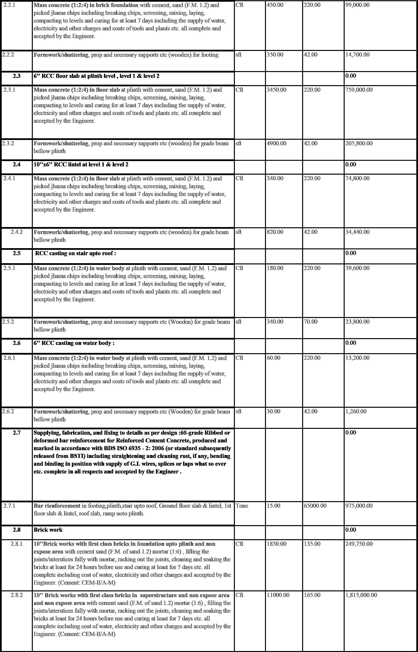
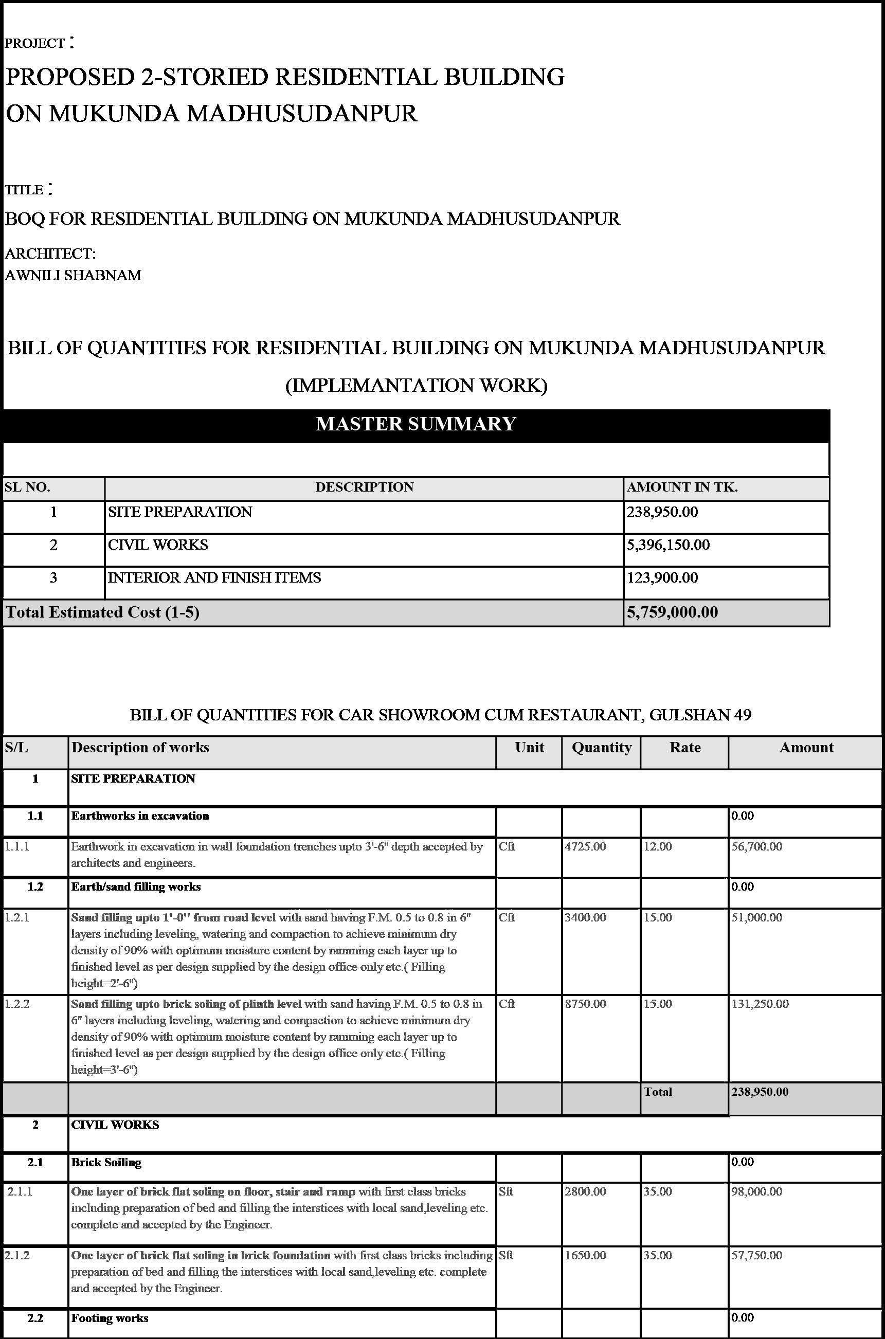
Fig 75: BOQ for the project
PROJECT 4 2-STORIED FAMILY RESIDENCE AT MUKUNDA MADHUSUDANPUR
PC 6.5: Nomination of quality and performance standards with regard to selected materials, finishes, fittings, components and systems.
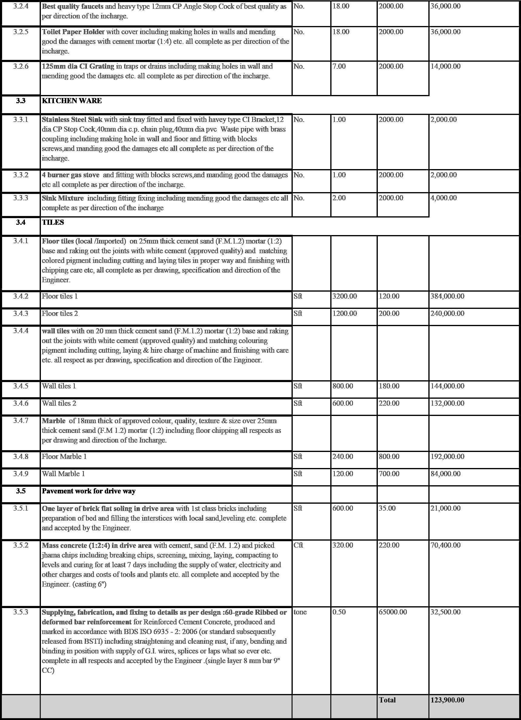
Architect nominated quality and performance standards regarding materials, finishes, fittings, and processes considering cost and industry standard. Local availability of materials and expertise of builders were facts to be considered while specifing materials. 1st class, machine cut bricks were specified for 5” brick works, the nearest source would be Satkhira district. Burma teak wood was selected for door and windows considering its beautiful texture. Local tiles and sanitary wares were nominat-ed to optimize transport costs.(Fig 76)
51
Fig 76: Specification of material and processes
Water body Detail
PROJECT 4 2-STORIED FAMILY RESIDENCE AT MUKUNDA MADHUSUDANPUR
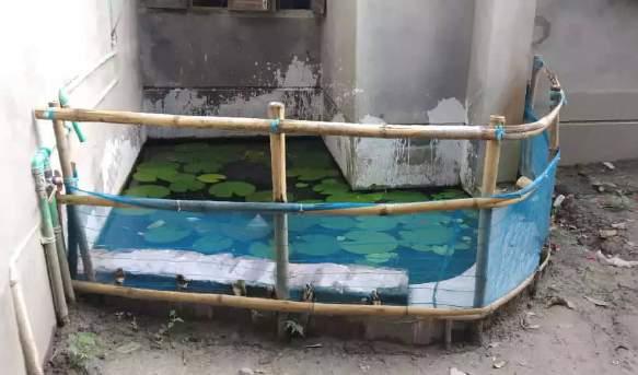
PC 9.8 : Clear and consistent communication with client and relevant stakeholders throughout project.
BThe client didn’t want to construct the waterbody initially. He thought the construction process and mainte-nance would be complicated. Architect had a conversation with the structural engineer and produced detail drawing for waterbody construction(Fig 77). The area was prone to excessive rain and flooding. A drainage system was developed to carry excess water to the pond on the north side in case of water overflows. Archi-tect sat with builders and explained the drawings and processes needed to be undertaken. Once the build-ers were confident they could manage to handle the construction, the client was also convinced to do it.
Section BB
52
ARCHITECT : Proposed two residential Mukunda
SCALE :---------AS SHOWN SHEET NO :---------A-11 AWNILI SHABNAM B.Arch Cs-025 ENGINEER ENGR. ZAHIDUL BSC. (CIVIL) PROJECT TITLE DRAWING APPROVED FOR CONSTRUCTION Working Drawing: Waterbody DRAFTING BY : AWNILI SHABNAM CLIENT: ABDUL MAJID Dag no:1308 Khatian no:398 Village-Mukunda Union-Bishnupur Upozila -Kaliganj. District -Shatkhira LOCATION: &R.L. P.L. P.G.L.
Madhusudanpur
0 10" 20" 30" 40" 50" 60" 70" 80" 90" 100" 110" 120" 130" 140" 10" 20" 30" 40" 50" 60"
Water body Detail
B B
&R.L. P.L. P.G.L.
30" 40" 50" 60" 70" 80" 90" 100"
120" 130" 140"
110"
Fig77:Waterbody detail drawing
PROJECT 4 2-STORIED FAMILY RESIDENCE AT MUKUNDA MADHUSUDANPUR
Proposed
9.1 Knowledge and implementation of appropriate practice model to ensure efficient, effective and ethical professional service.
The practice model was simple and straightforward. The architect was appointed to provide architectural and structural design, documents and provide support for supervision of construction.She subcontracted structural design to thrid part consultant.As this was a small residence the client himself played the role of construction manager and organised necessary builders and technicians to carry out construction process.
PC 9.6 : Knowledge and application of professional ethics and ethical practices in respect to practice management and provision of professional service.
Prior to construction, the design and drawing had to be approved by the local authority, in this case, it was Union Parishad. A DIT sheet containig the location of the site, area, a proposed design, break down of compliance with the law had to be submitted to them. In rural areas, it was not uncommon to overlook the process due to reluctancy and ignorance. In this case, the design followed the BNBC code and the DIT sheet was prepared by the architect and supplied to the client(Fig78). He organised the process of approval.
PC 9.7 : Knowledge of legal and regulatory requirements and obligations in regard to architectural practice, practice management and registration as an architect.
The architect was an associate member of IAB (Institute of architects Bangladesh). According to BNBC, an associate member can design upto 1000sqm and 4 storey building. In this case, the area of the building is aorund 400 sqm and its 2 storeys. So, the architect is qualified to design this building. An assosiate member needs to work for two years in industry or 4 years in academia under the supervision of a regis-tered full memeber and after that sit for a qualifying examination. Upon completion of work experience and exam, he/she can become a full member.
53
Scale =1:100 Scale =1:100 Scale =1:100 Scale =1:100 Scale =1:100 Scale =1:100 Scale =1:100 Scale =1:100 Scale =1:400 Scale =1:200 ARCHITECT
two storied residential building on Mukunda Madhusudanpur SCALE :---------AS SHOWN DATE :---------20/08/2014 SHEET NO :---------A-01 DRAWING NO :--W-01 AWNILI SHABNAM B.Arch Cs-025 ENGINEER PROJECT TITLE DRAWN BY ABDUL MAJID Dag no:1308 Khatian no:398 Village/MouzaMukunda Madhusudanpur Union-Bishnupur Upozila -Kaliganj. District -Shatkhira OWNER: LOCATION: SIGNATURE: ENGR. ZAHIDUL ISLAM BSC. (CIVIL) AWNILI SHABNAM M bed Bed 4800x3500 Guest bed 4900 3600 LIVING 3900x4500 Dining 6300x 4200 Foyer Kitchen 2250x 3000 Kit.store 19500x1650 Servent Bed 1950x2400 Water body Closet Ground floor plan Veranda 1950x1000 toilet 1200x 3000 Family Living 4800x1600 Patio 4800x1600 Patio 1600x3000 toilet 2250x1600 Patio Front 9000x1000 toilet 1300x1500 Lobby
Water South elevation North elevation West elevation East elevation Section AA 1st floor plan Store bed 5100x3900 toilet Family Living 6300x 4200 Child. bed 4900 3600 Child Bed 3900x4500 toilet 2250x1600 Balcony Balcony 1600x1600 Balcony toilet 1300x1500 Terrace 9200x6000 Roof plan Site plan Proposed area P.G.L. R.L. P.L. sand filing mass concrete 250 mm brick wall upto plinth 25 mm D.P.C P.G.L. R.L. P.L. sand filing brick flat soling mass concrete 250 mm brick wall upto plinth 75 25 mm D.P.C Foundation for 3000mm wall Foundation for 6000mm wall 75 brick flat soling
Layout plan
Fig 78: Draft DIT sheet for approval
BONOCHAYA INTERIOR PROJECT 5
Professional project
Location: Basundhara,Dhaka,Bangladesh
Time period : Sept2014- May2015
BACKGROUND
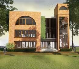
“Bonochaya” is a 6 storied apartment building constructed by Union Holdings LTD, a private developer company. The building was constructed on a 3600sqm land. The company had an agreement with the land owner that they would develop the land and construct the building with 3 units on each floor.client was promised 40% of the building, which is 6 apartments. Others belonged to Union Holdings LTD to sell in the open market.
“Architect’s” was appointed as the architectural design consultant for Bonochaya. They provided complete design and construction documents. Union Holdings LTD had their listed builders and sub-contractors to execute the construction. The superstructure, exterior facade, functional spaces were constructed as per de-sign provided by
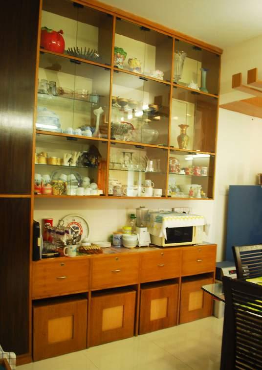
“Architects”.A basic finish and fixtures were provided for interior by Union Holdings LTD, but there was the scope of improvisation depending on the choice and preference of each flat owner. While some of them were satisfied with the basic interior, others appointed interior designers, architects to design their interior spaces.
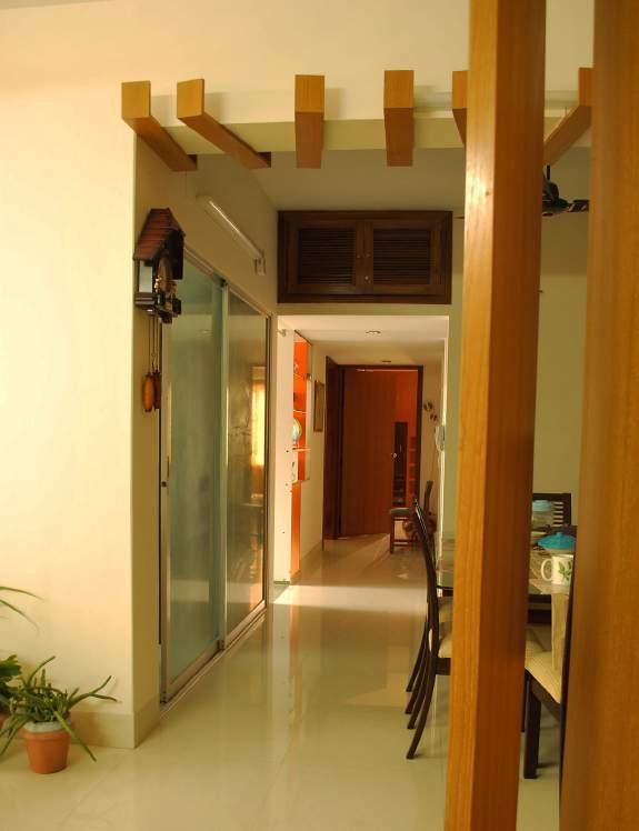
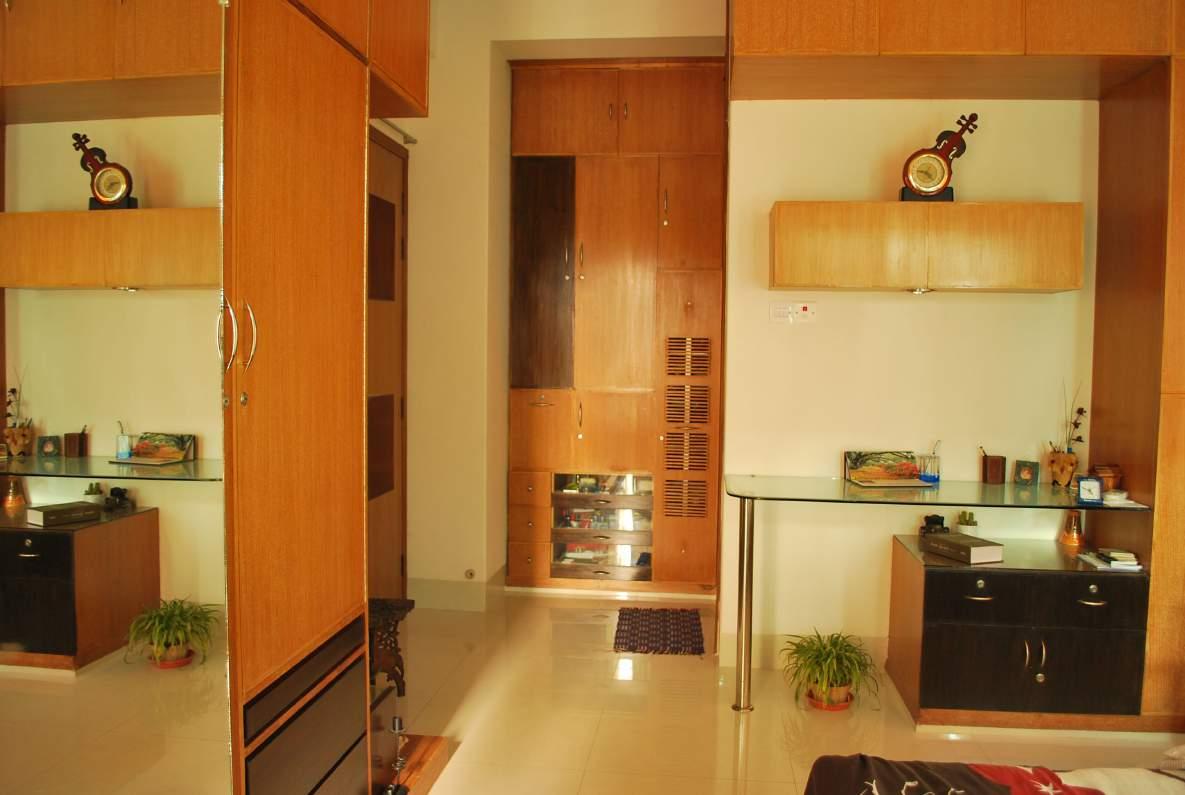
The owner of Flat 5C appointed the architect (Author) to design and decorate interior spaces of his apart-ment. The architect was involved at the final stage of construction to propose a comprehensive interior de-sign and execute any modification necessary in the layout to accomodate design ideas.
55
Fig 79: Interior space
BONOCHAYA INTERIOR PROJECT 5
PC1.1: Preparation & endorsement of an agreement between client and Architect. This agreement will clearly communicate terms, services to be provided and fees appropriate for the scale and type of project
The architect was involved in the project at the stage when the building was constructed and interior layouts were being modified per client requirement(Fig80,81). She was tasked to accomodate these changes and make appropriate sug-gestions to produce a coherent interior design. The agreement between the architect and the client was verbal, there was no formal document. Services:
• Modification of interior layouts as required.
• Provide working drawings for interior space.

• Specification of furniture and fixture, paint,tilesworks etc.
• Detail design and drawing for the toilet and kitchen cabinets.


• Co-ordinate with subcontractors and relevant stakeholders.
• Supervision of ongoing construction work.
Payments:
• Design cost: Payment was resolved at the rate of 70tk/sqft for the total floor area of the apartment.

• Supervision cost: The architect’s responsibility included supervision of tilework/painwork/carpenter’s work etc. The cost of supervision was fixed at the rate of 70tk/per visit.
PC1.5: Knowledge of different procurement processes available and evaluation of the impact these have on the project.
The probable procurement options for the project were the followings:
1.Construction cost plus lumpsump / Construction cost plus parcentage: A form of building contract where the contractor is reimbursed for the costs they have actually incurred in the construction of the project, plus a fee to cover their overheads and profit. This fee is usually either a fixed amount or a percentage of the final actual costs.
2.Lumpsum:
A form of project management where the architect manages the design and completion of the project on behalf of the client. The architect and client have a service agreement and the architect is responsible for design, documentation, ten-dering, setting up the building contract (between the owner and contractor) and administering the contract.
3.Payment/unit of floor area :


Specially in the case of interior design, a contract system that allows payment per unit of designed floor area is widely practiced.
In this case, considering the small scale of the interior project and as most of the subcontractors are appointed by the developer company i.e. Union Holdings Ltd, the 3rd option ( payment/unit of floor area) was condered most appropri-ate mode of procurement.
56
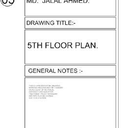
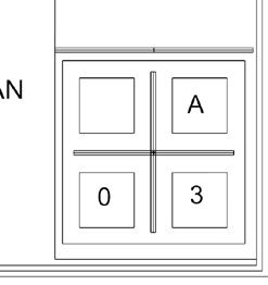
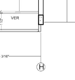
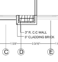
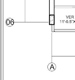
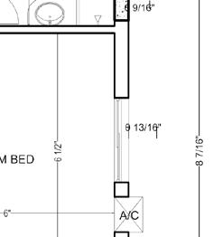
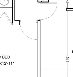
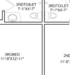
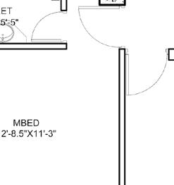
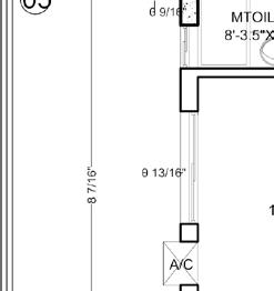
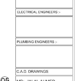
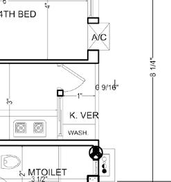
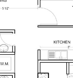
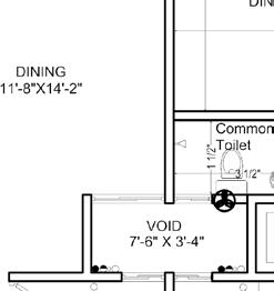
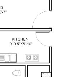
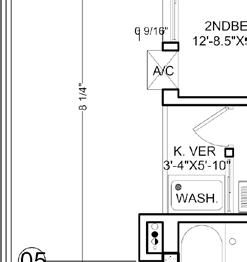
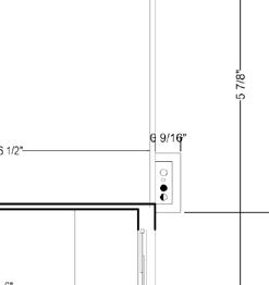
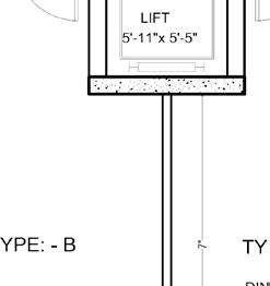
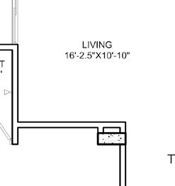
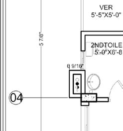
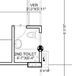
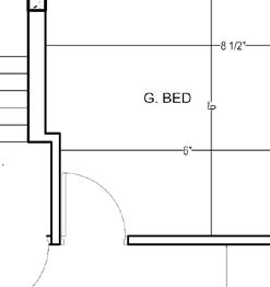
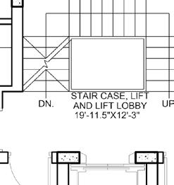
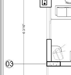
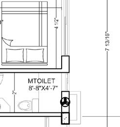
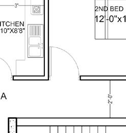
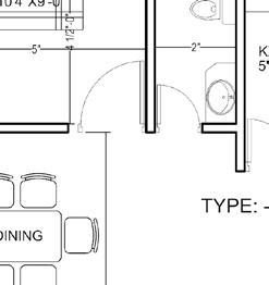
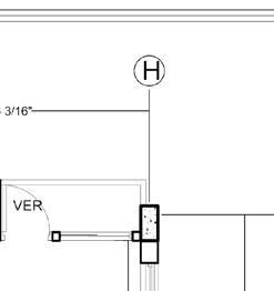
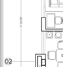
5TH FLOOR PLAN ( SOUTH SIDE ) FOR A.B.M.ABDUL MANNAN N STAIR CASE, LIFT AND LIFT LOBBY 19'-11.5"X12'-3" UP. DN. LIFT 5'-11"x 5'-5" 3RDTOILET 7'-1"X4'-7" PROJECT. CONSULTANTS: DHANMONDI R/A DHAKA-1205. ARCHITECT'S TEL: 8120054, CELL: 01711-693822 HOUSE NO. 27/1, ROAD NO.13A mail-architects.admin@gmail.com ARCHITECTS NISHAT AFROSE (A-099) ELECTRICAL ENGINEERS :PLUMBING ENGINEERS C.A.D. DRAWINGS MD: JALAL AHMED. DRAWING TITLE:5TH FLOOR PLAN. GENERAL NOTES :THIS PRESENTATION DRAWING, WORKING DRAWING MAY BE CHANGED ON ACCOUNT OF TECHNICAL ACCURACY AND ELEVATION TREATMENT. FRONT VERANDAH SIZE MAY ALSO BE CHANGE DUE TO ELEVATION. A 0 3 28 DECEMBER, 08 SCALE AS SHOWN DATE AUTHORIZED SEAL SIGNATURE:SAKLAYEN BULBUL (B-023) STRUCTURAL ENGINEERS :CLIENT: DEVELOPER: RESIDENTIAL BUILDING PROPOSED SIX STORIED UNION HOLDINGS LTD. REVISED DATE: AT BASHUNDHARA, DHAKA MTOILET 8'-3.5"X5'-5" MBED 12'-8.5"X11'-3" 3RDBED 11'-8"X12'-11" 2NDBED 12'-8.5"X9'-7" DINING 11'-8"X14'-2" LIVING 16'-2.5"X10'-10" VER 5'-5"X5'-0" 2NDTOILET 5'-0"X6'-8" 3RDTOILET 7'-1"X4'-7" MTOILET 3RDBED DINING LIVING 2ND TOILET 5'-0"X6'-0" G. BED KITCHEN 9'-9.5"X5'-10" K. VER 3'-4"X5'-10" A B C D E F G H A B C D E F G H 01 02 03 04 05 06 01 02 03 04 05 06 2ND BED 11'-8"X12'-11" M BED KITCHEN A/C A/C A/C 1'-3" 1'-8" 1'-8" 1'-3" 1'-3" 1'-3" 1'-3" 1'-3" TYPE: B TYPE: C A/C WASH. WASH. VER VER 11'-0.5"X4'-2" 3" R. C.C WALL A A A 13'-11 5'-5 3'-5 6'-9" 3'-5 5'-51 2 13'-1 13'-11 5'-5 3'-5 6'-9" 3'-5 5'-51 2 13'-1 24'-7" 5" CLADDING BRICK 3" R. C.C WALL 5" CLADDING BRICK 12'-8" 11'-1" 18'-4" 2'-1" 13'-8 12'-8 14'-5" 17'-6 1 2 2'-8 1 2 5" 12'-8 4'-6" 8'-10 5'-11" 13'-6 13'-1 7'-9" 14'-9" 11'-8" Common Toilet 2'-1" 3RD BED 12'-6"X9'-0" MTOILET 8'-8"X4'-7" DRESS 3'-0"x4'-7" TYPE: -A 2ND BED KITCHEN TOILET 4'-5" 9'-4"X10'-5" 6'-6"X10'-10" WASH. VER VER DINING 1'-3" LIVING 19'-0" 17'-9" 9' 5TH FLOOR PLAN SOUTH & EAST SIDE FLAT) FOR A.B.M. ABDUL MANNAN Chip Engineer VOID 7'-6" X 3'-4" W.M. VER M BED 16'-6"X10'-0" 7'-6" 3'-7" 80'-10" 25'-7
Fig 81: Original plan of flat 5-C, Bonochaya Apartment
Fig80:Revised plan of flat 5-C, Bonochaya Apartment
PROJECT OUTLINE BASED ON CLIENT'S REQUIREMENT
BONOCHAYA INTERIOR PROJECT 5
PC1.7: Preparation of project brief for approval by client and relevant stakeholders.
The architect was responsible for a complete make over of the interior space. The family was composed of 4 memebers - husband, wife, one son and one daughter. The apartment had 4 bedrooms and 4 toilets. Masterbed was allocated for the couple, 2nd and 3rd bedrooms were for siblings and one guest bedroom cum study space. Each bedroom had dif-ferent furniture/fixture requirements. Three of the four toilets were attached while one was common. Living and dining space had to be combined to form an active mono space. The kitchen had to be open and well-lit. Each space had color and illumination requirements based on fuctional preferences. A detailed outline of project requirements was produced to carry on the further design process. (Fig82)
PC2.3: Evaluation of factors influencing and impacting on project cost.
The outline of project requirement in Fig82 points out several factors that may influence and impact project cost:
1.Excessive no of toilets: Construction and finish of 4 toilets would be very expensive.The basin and WC, shower tray,shower curtain,storage cabinet and quality floor & wall tiles would definitely increase the cost.
2.Wall cabinet: The brief from client included a lot of storage cabinets/wall cabinets/closets in almost all the functional rooms.Material of these cabinet would influence the cost substantially - as there were various options starting from low cost laminated board to expensive, fine-grained Teak Chambal wood.
3.Floor and wall finish:The entire apartment floor and partial kitchen/toilet walls were to be covered with tiles.Price between local and imported tiles varied widely creating huge impact on the overall project cost.
4.Open kitchen: provision of open kitchen made it obvious to take additional measures to reduce heat and fume generation from cooking.Installation of exhaust fan and range hood on top of the stove became mandatory.
5.Lighting provision: Each room had to be provided with customised lighting solutions.Combination of different lighting fixture and components would influence the expenditure of the project.
57
S/LFUNCTIONAL SPACE AREAFURNITURECABINET FIXTURELIGHTINGCEILINGFINISH 1.0 BEDROOMS 1.Bed 1.Transformation of an old closet to suit new interior 1.Light floor tiles 2.Study table 2.Storage cabinet near toilet 2. Off-white paint on wall 1.Bed 1.Closet 1.Light floor tiles 2.Study table 2.Dressing table 3.Book Case 1.Bed 1.Closet 1.Light floor tiles 2.Divan 2.Dressing table 2. Off-white paint on wall 1.Bed 1.Light floor tiles 2.Study table 2. Off-white paint on wall 2.0 COMMON SPACES 1.Sofa set 2.Tea table 3.TV unit 2.Show case 1.Dinner table set (6p) 1.Light floor tiles 2.Seater 1.Shoe rack 1.Light floor tiles 2.Seater 3.Space divider 3.0 KITCHEN 1.Dark color floor 300x300mm 2.Wall tiles upto lintel level 3. Off-white paint on wall 4. Marble top 4.0 TOILETS 1.WC 1.Dark color floor 300x300mm 2.Basin 2.Wall tiles upto ceiling level 3.Shower tray 3.Shower curtain 1.WC 1.Dark color floor 300x300mm 2.Basin 2.Wall tiles upto ceiling level 3.Shower tray 3.Shower curtain 1.WC 1.Dark color floor 300x300mm 2.Basin 2.Wall tiles upto ceiling level 3.Shower tray 3.Shower curtain 1.WC 1.Dark color floor 300x300mm 2.Basin 2.Wall tiles upto ceiling level
2. Off-white paint on wall 1.Light floor tiles COMMON TOILET 1.4 21.67 1.Adequate illumination in study and dressing area 1.2 2ND BED 150.71 1.Adequate illumination in study and dressing area 1.1 MBED200.56 2. Off-white paint on wall 1.3 3RD BED196.64 1.4 4TH BED177.38 1.Closet 1.Ambient illumination 1.Adequate illumination in study and dressing area 1.1 LIVING ROOM166.42 1.Ambient illumination 1.Innovative solution covering the beam ruuning across the room 1.2 DINING ROOM171.97 1.Crockery cabinet 1.Provision of adequate and ambient illumination. 2.Off-white paint on wall 1.3 FOYER52.2 1.Ambient illumination. 1.Aesthetic solution to define the space 2. Off-white paint on wall 1.1 KITCHEN78.83 1.L-shape top 2. Storage cabinet 1.Stove 2. Double sink 1.Ambient illumination. 1.Adequate illumination. 1.Aesthetic solution to define the space 1.2 2ND TOILET28.97 1.Storage cabinet 1.Ambient illumination. 1.1 MTOILET33.47 1.Storage cabinet 1.Ambient illumination. 1.Ambient illumination. 1.3 3RD TOILET32.46 1.Storage cabinet 1.Ambient illumination.
Fig 82: Outline of project requirement
BONOCHAYA INTERIOR PROJECT 5
PC 6.4:Timely completion and communication of accurate and comprehensible documents that will include, as required, drawings, models, specifications, schedules and other relevant modes of information.
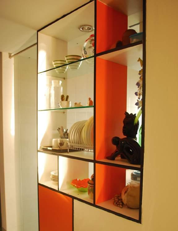
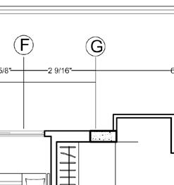
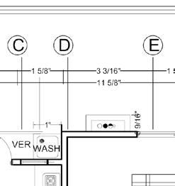
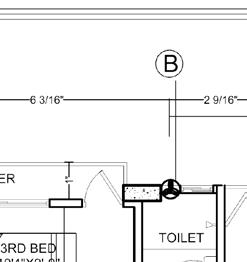
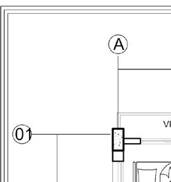
The architect was responsible to provide detail working drawings of interior spaces, kitchen & toilet cabinet drawings, fixture specifications, tiles layout, wall cabinets drawing in bedrooms, ceiling works, electrical fixture, and lighting layouts. Working drawing of major functional spaces and corresponding photo images of the space after the execution of the design are explained in pages (58-61).
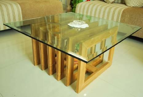
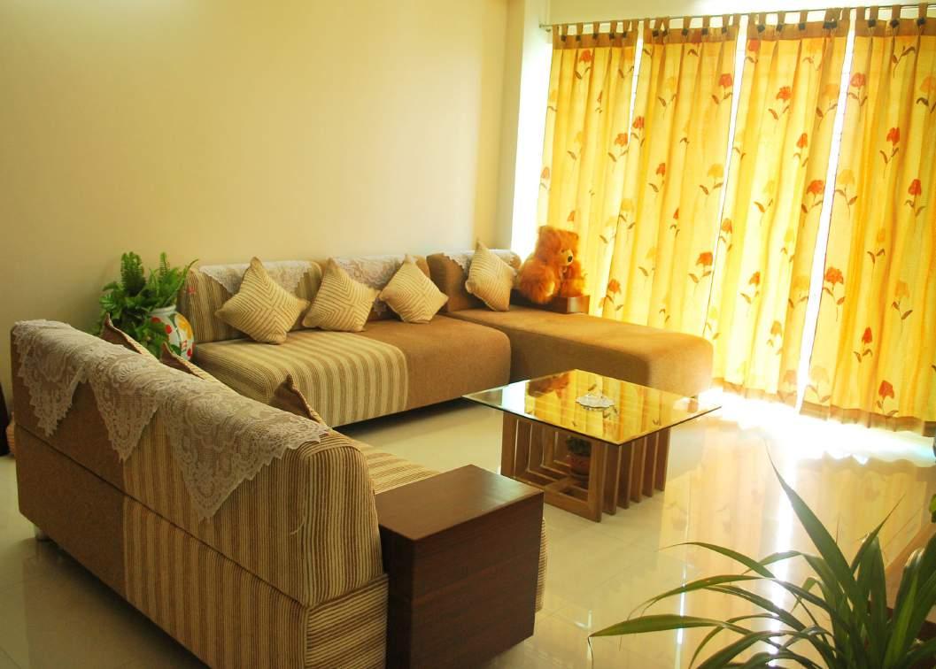
Living space:
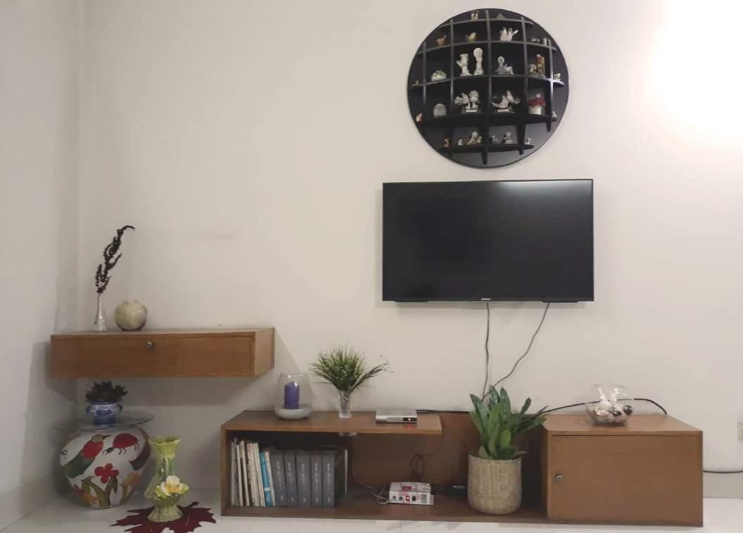
The living space was designed to be warm and green, welcoming to the guests. The lounge set includes one 3-seater, one 2-seater and one side sofa providing enough sitting space for the family and guest. The tea table at the center was designed and constructed specifically for the spot with the elegant texture of Burma Teak and louvred space inside to host pot-plants. The opposite wall of the lounge was mounted with a smart TV and a unit to store accessories, books and display pot-plants.
58
Fig83a: Living space
Fig 83b: Working drawing of living space wall unit
BONOCHAYA INTERIOR PROJECT 5
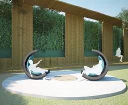
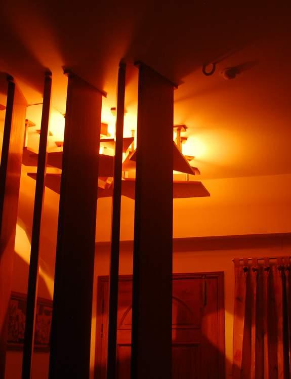
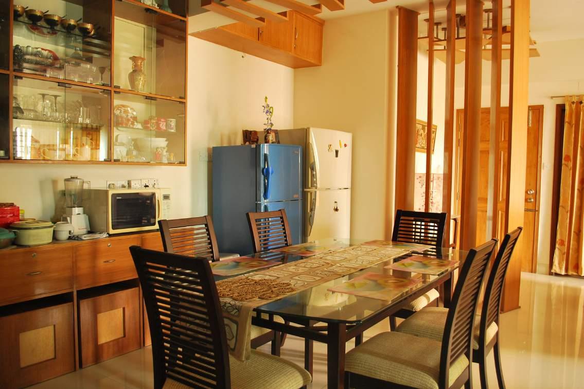
Foyer and Dining space:
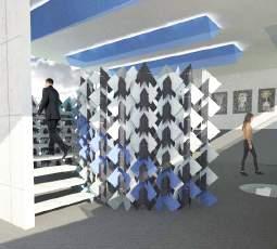
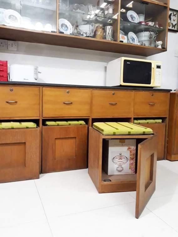
The foyer, dining room and living room were part of a mono-space. The architect had to be sensetive in her interven-tions so that each space is identified in terms of their fuction yet not too rigidly enclosed. The angled vertical louvres and ceiling-works were introduced to define the foyer area. The space-divider showed a glimpse of the interior through the slits instead of entirely blocking the view. The dining space was provided with a six-seater dining table and cabinet for crockery.
PC 4.3 : Application of creative imagination and aesthetic judgement to produce coherent design.
The brief required to provide adequate sitting provisions to accomodate guests or host family func-tions.Another important issue was to create as much storage options as possible.The architect thought of an innovatiove approach to resolve these issues in a single solution.The cabinet on the dining space was fitted with portable seats that could be transported on wheels and easily slided to desired spaces when neces-sary.These portable seats with operable doors had capacity to store things inside.The box like seats, with contrasting texture of light Kerosine wood and brownish Teak Chambal wood were aesthetically pleasing as well as fuctionally efficient serving dual purpose.(Fig84a)
59
Fig84b:Working drawing of dining space cabinet
Fig84a: Foyer and dining space
BONOCHAYA INTERIOR PROJECT 5
Master Bedroom:
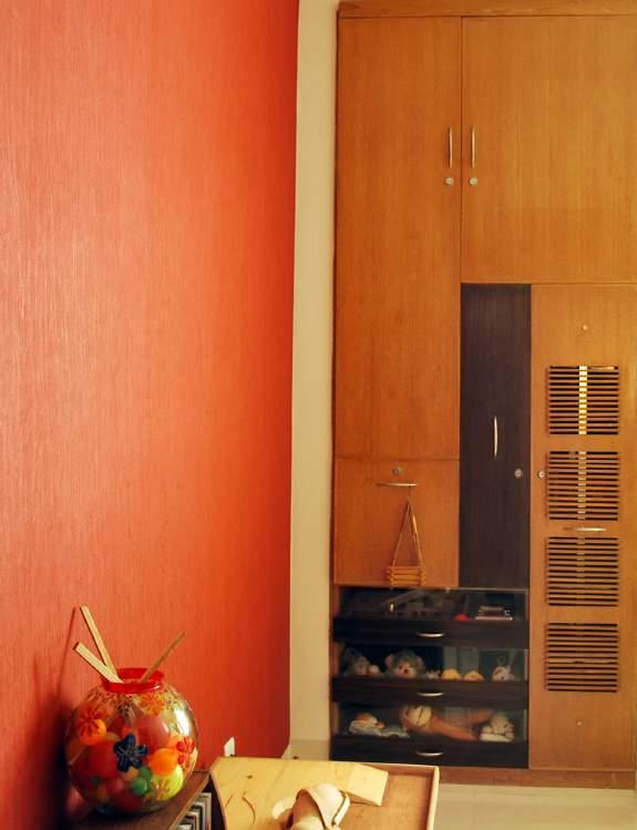
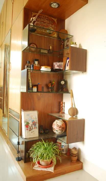
The master bedroom was spacious and well-illminated with an open balcony on the west side. The family owned a previous wooden closet that was to be retrofitted to match the interior of the new apartment. The closet doors were replaced with new ones and fitted with a mirror(Fig 85a). It was also extended on one side to accomodate a display rack for decorative objects(Fig 85c). The architect combined the study table and closet (on the other wall) for optimum space utilisation as well as an elegant look.
60
Fig 85a : Master Bedroom
Fig 85b: Working drawing of master bed furni-
Fig 85c: Extension of existing closet
BONOCHAYA INTERIOR PROJECT 5
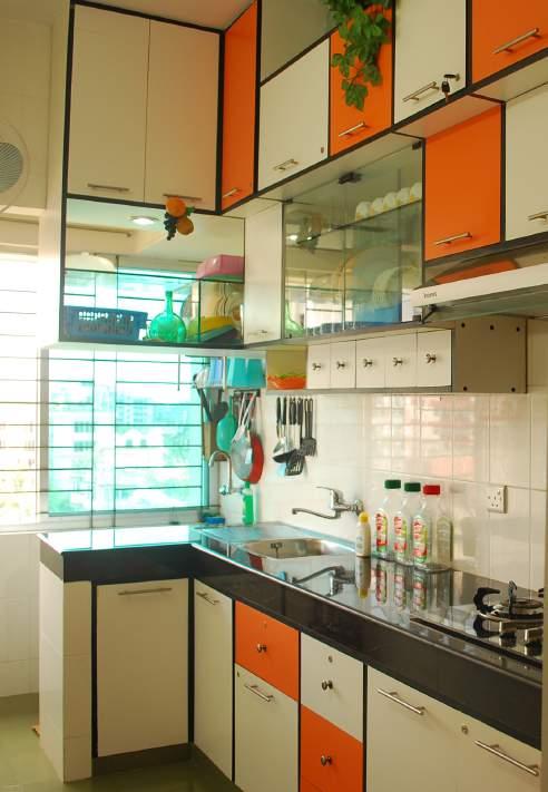
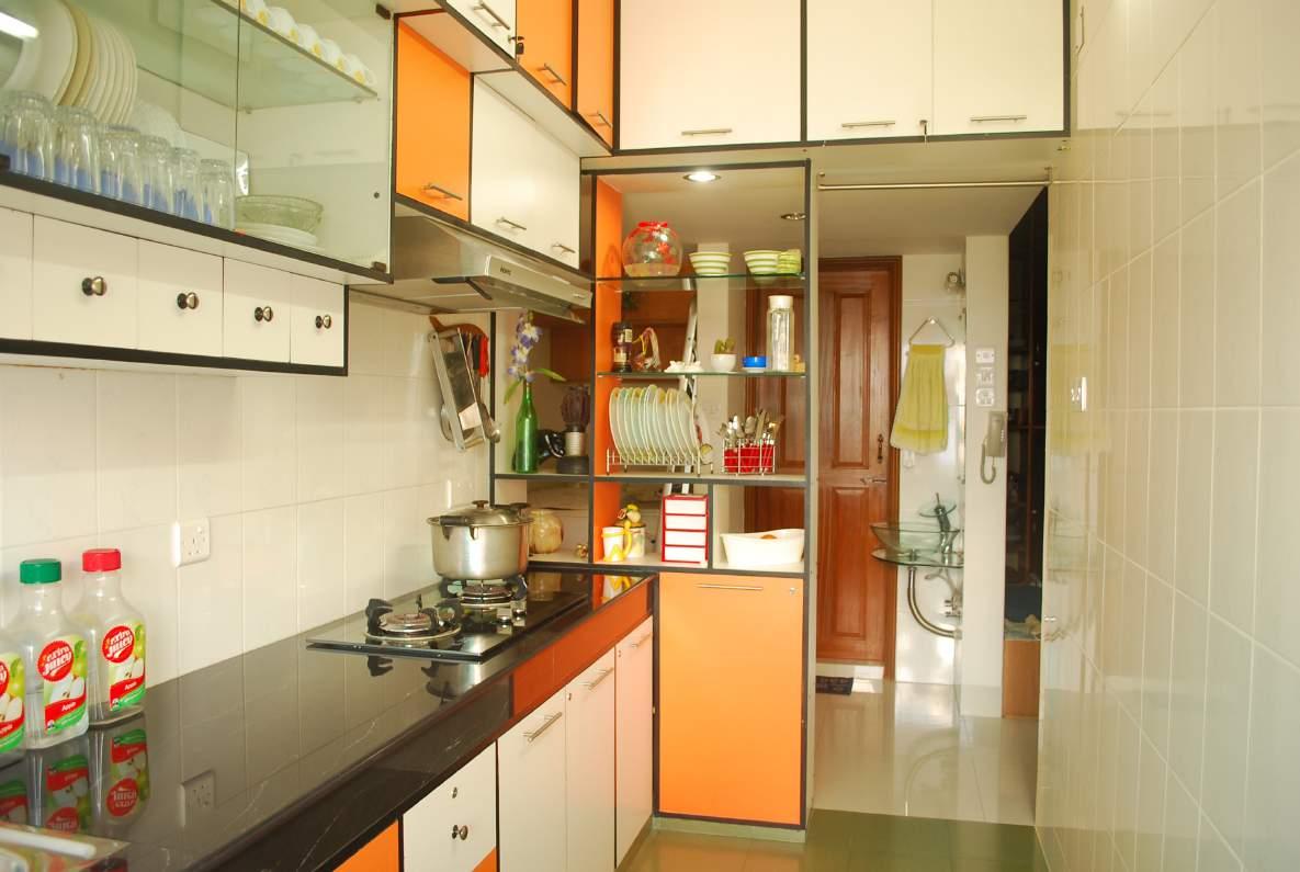
Kitchen:
The kitchen was open,well-illuminated and vibrant with orange-white compostion inspired by artist Mondri-an’s paintings (Fig 86a).
Adequate storage was provided for kitchen utensils and dry food. Black marble kitchen top and flat stove with a hood were installed. One exhaust fan and one wall fan was provided for proper ventilation. The kitchen cabinets were composed of orange and white laminated boards with black edging. Open rack with decoration pieces and crockery acted as a space devider between the kitchen and adjacent corridor. The floor was laid with square (12”x12”) local tiles which were less expensive compared to other imported tiles (87tk/sqft).
61
Fig 86a: Open space kitchen
Fig86b: Working drawing of kitchen cabinet
BONOCHAYA INTERIOR PROJECT 5
PC: 4.6 Investigation and integration of appropriate material selection for the project design.
The materials were selected based on their functionality,availabilty, cost and aesthetic appearance.
Door: Solid wooden (Burma Teak) door with the customised design was selected for the entry door due to aesthetic ap-peal. Flush MDF doors were considered for bedrooms to minimize expenditure. Toilets were fitted with panel doors coated with paints for moisture protection.(Fig 86b, Section1)
Windows: They were fitted with Aluminium and glass panels for convenient and cost-effective operation.
Cabinets: All the cabinets and closets except in toilet & kitchen were composed of two types veneer boards- Burma Teak boards for front faces and Garjan boards for interior partitions & back face. Cabinets in the toilet and kitchen were made of the laminated board as these spaces are prone to moisture.
Tiles: Kitchen and toilet floors were laid with 12”x12” local floor tiles (Fig 86b, Section 4.3) while the other spaces had 24”x 24” imported floor tiles (Fig 86b, Section 4.2) with impressive patterns. The walls of toilet and kitchen were covered with 12”x24” wall tiles as protection from dampness(Fig96)
PC 6.5: Nomination of quality and performance standards with regard to selected materials, finishes, fittings, components and systems.
Architect nominated quality and performance standards regarding materials, finishes, fittings and processes considering cost and industry standard. Union Holdings Ltd. had a list of suppliers and brands that they preferred to appoint. Most of the materials were specified following the list unless any specific requirement was needed to tend. For example, the glass basins had aluminium pedestal support available on the market, that wasn’t aesthetically pleas-ing. The architect suggested to place the glass bowl on top of a glass plate and mount it on the wall using a flexible steel pipe and fittings. So only the glass bowl was nominated from the listed suppliers discarding the pedestal support. The base plate and support were custommade from related manufacturers using proper drawings. (Fig 86a)
Fig 86b shows BOQ for interior finish items i.e. door and window schedule, sanitaryware and kitchenware, tiles, electri-cal fitting, and fixture, etc.
INTERIOR AND FINISH ITEMS
DOOR and WINDOW
Door frames with matured natural seasoned Burma Teak Chamble wood of required size including painting two coats of coal tar to the surface in contact with wall, fitting and fixing in position
Bedroom Flush door D2(3'-6'' x 7'-0'' x 10'') wooden frame with swing shutter panel.
fitting and fixing of Aluminium sliding doors with 6" silver color, aluminium section (KAI), with 10mm Non-Tempered translucent glass complete with all other accessories as per direction of the Engineer in-charge.
Supply,fitting and fixing of aluminium sliding and fix window with 4" silver color,aluminium section(KAI) with 5mm clear glass including all accessories
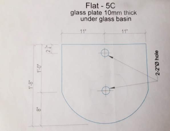
Commode Orient WC + WT P-Trap White from RAK
Commode Tampa WC + WT S-Trap Ivory from RAK
Basin 16" glass bowl from RAK resting on top of 8mm glass plate
Supplying, fitting and fixing super quality Mirror with all necessary fitting including making holes in wall manding good the damages etc all complete as per direction of the incharge.
Best quality faucets and heavy type 12mm CP Angle Stop Cock of best quality as per direction of the incharge.
Toilet Paper Holder with cover including making holes in walls and mending good the damages with cement mortar (1:4) etc. all complete as per direction of the incharge.
KITCHEN WARE
Stainless Steel Sink with sink tray fitted and fixed with havey type CI Bracket,12 dia CP Stop Cock,40mm dia c.p. chain plug,40mm dia pvc Waste pipe with brass coupling including making hole in wall and fioor and fitting with blocks screws,and manding good the damages etc all complete as per direction of the incharge.
4 burner gas stove and fitting with blocks screws,and manding good the damages etc all complete as per direction of the incharge.
Sink Mixture including fitting fixing including mending good the damages etc all complete as per direction of the incharge
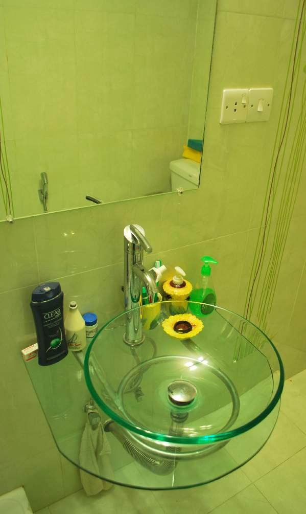
TILES
Floor tiles (local /Imported) on 25mm thick cement sand (F.M.1.2) mortar (1:2) base and raking out the joints with white cement (approved quality) and matching colored pigment including cutting and laying tiles in proper way and finishing with chipping care etc, all complete as per drawing, specification and direction of the Engineer.
Floor tiles 1 (24"x24") approved pattern RAK standard 1200.00 240,000.00
Floor tiles 2 (12"x12") local product AZAD Tradings standard 213.00
wall tiles with on 20 mm thick cement sand (F.M.1.2) mortar (1:2) base and raking out the joints with white cement (approved quality) and matching colouring pigment including cutting, laying & hire charge of machine and finishing with care etc. all respect as per drawing, specification and direction of the Engineer.
Wall tiles 1(24"x12") local product AZAD Tradings standard 876.00 spot light 4"
62 S/L Unit Rate 1.0 1.1 1.2 No. 20000.00 1.3 No. 2000.00 1.4 No. 1000.00 1.5 1.6 Sft 530.00 1.7 Sft 530.00 1.8 Sft229.00500.00 2.0 2.1 No. 5428.00 2.2 No. 5480.00 2.3 No. 3000.00 2.4 No. 1100.00 2.5 No. 5000.00 2.6 No. 2000.00 2.7 No. 2000.00 2.8 No. 2000.00 3.0 3.1 No. 1800.00 3.2 No. 2000.00 3.3 No. 2000.00 4.0 4.1 4.2 Sft 200.00 4.3 Sft 120.00 4.4 4.5 Sft 180.00 5.0 No. 800.00 No. 1200.00 5.1 No. 700.00 5.2 No. 600.00 5.3 No. 1200.00 5.4 No. 2800.00 5.5 No. 850.00 10,960.00 Basin EMMA 16 ylb over counter white 2,200.00 ELECTRICAL
7.00 2.00 Supplying,
FITTING & FIXTURE
114,500.00 25,560.00 816660.30
5100.00 2800.00 1200.00 3000.00 5600.00 10800.00 5600.00 157,680.00 14,000.00 9,000.00 SANITARYWARE 40,810.00 4,000.00
Exhaust fan
8.00
9.00
Tube light 4'
Wall Bracket light
18.00 36,000.00
18.00 36,000.00
2.00 4,000.00
1.00 2,000.00
1.00 1,800.00
2.00
3.00
4.00
3.00 6,000.00
and mending good the damages. all complete as per drawing, direction of the Engineer. (All sizes of wood are finished). Entry Design door D1 (3'-6'' x 7'-0'' x 10'') wooden frame with swing shutter panel. 1.00 20,000.00 Bedroom door D4 (7'4" x 7'-0"x4") Aluminium frame with 2 sliding shutter panel 51.31 Veranda door D5 (11' x 7'-0"x6") Aluminium frame with 3 sliding shutter panel 77.00 Toilet Panel door D3(2'-6'' x 7'-0'' x 10'') wooden frame with swing shutter panel. 4.00 TOTAL 20,000.00 2.00 10,856.00 27,194.30 Amount BILL OF QUANTITIES FOR INTERIOR WORK ON FLAT 5C, BONOCHAYA APARTMENT Description of works Quantity 6.00 Wall mounted fan Tube light 2' 5.00 1.00 Ceiling fan 1.00 125mm dia CI Grating in traps or drains including making holes in wall and mending good the damages etc. all complete as per direction of the incharge. 7.00
Fig 86a: Glass basin on master toilet
Fig 86b: BOQ for interior work on flat 5C, Bonochaya Apartment Building
BONOCHAYA INTERIOR PROJECT 5
PC 6.2: Continuing coordination and integration of information and project material from relevant consultants, specialists and suppliers.
The project required communication with the engineers from Union Holdings Ltd, material suppliers, and contractors who were responsible for interior construction. Fig 87d shows an electrical conduit layout for the apartment that was collected from Union Holdings Ltd. The electrical layout was subjected to modification several times based on changes in interior design predominantly on the re-position of furniture. The architect had to negotiate the changes with the en-gineer.
Fig 87a, 87b, 87c show bill for aluminium widow fittings, toilet fixtures and tiles. The architect had to supervise the ma-terials’ order and delivery
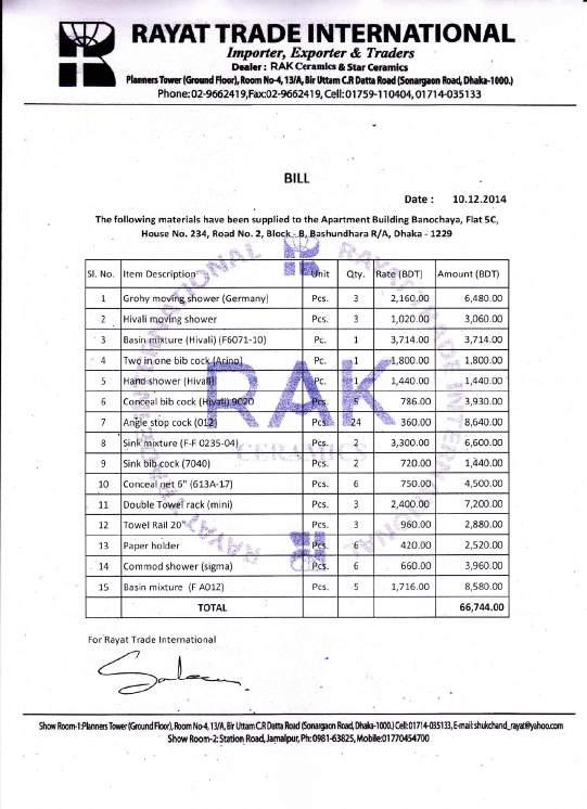
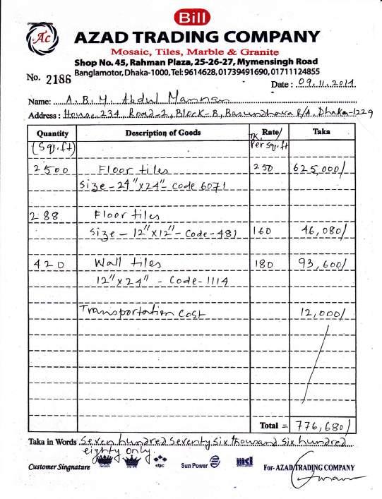
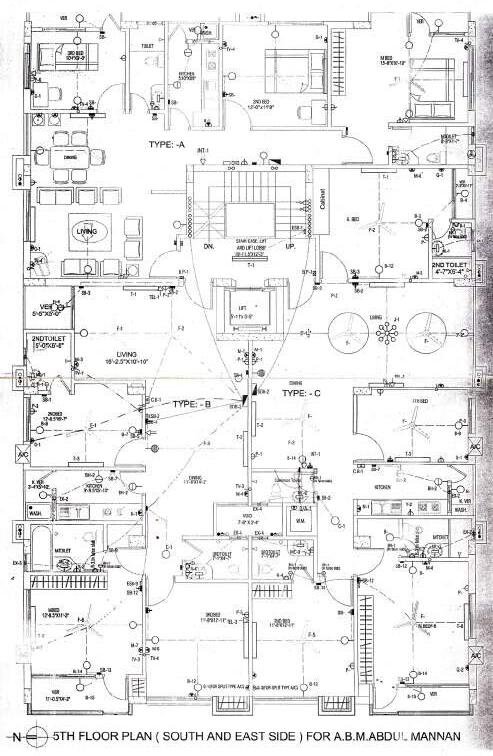
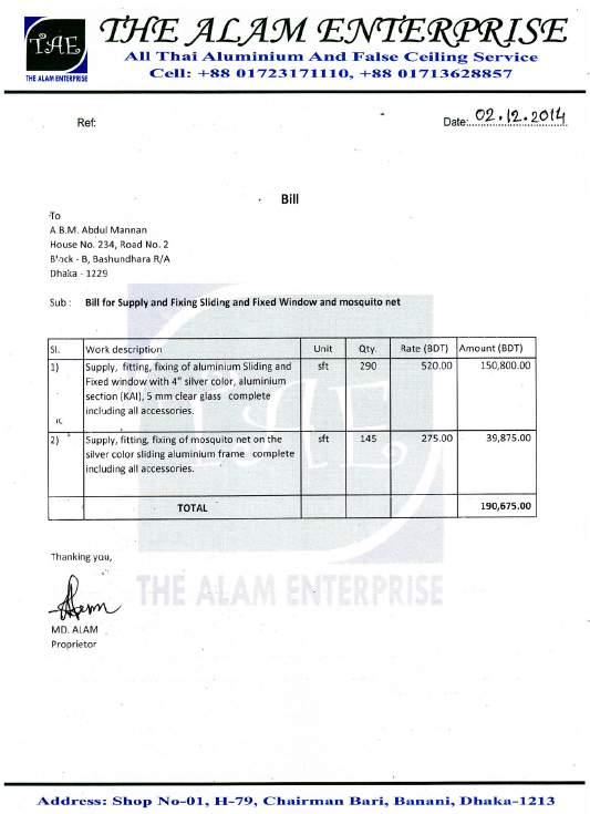
PC 9.1:Knowledge and implementation of appropriate practice model to ensure efficient, effective and ethical professional service.
Union Holdings Ltd. acted as a project management body appointing “Architect’s” as an architectural de-sign consultant. The developer company had in house engineers to resolve structural, electrical and plumb-ing design. Each apartment in the entire building belonged to different owners. The owner of flat 5C ap -pointed the author for interior design and construction. The author co-ordinated with engineers and techni-cians from Union Holdings to carry out design modifications and interior constructions. The author didnt have authority over the builders, drawing modifications had to be approved by Union Holdings first. It was not convenient as some decisions had to be made on site depending on the practical scenario.
PC 9.8 : Clear and consistent communication with client and relevant stakeholders throughout project.
The design and construction of the interior project integrated a process of ongoing liason among the client, architect, Union Holdings and subcontractors. The architect had to get the approval of the design from the client. Then it had to go through the engineers of Union Holdings for necessary modification. Once the de -sign was finalised the subcontractors and technicians were to be contacted for construction. The architect had to report the client regarding the progress of work from time to time throughout the project.
63
Fig87a: Bill for aluminium window and Fig 87b: Bill for floor and wall tiles
Fig 87c: Bill for sanitarywares.
Fig 87d: Electrical conduit layout
BONOCHAYA INTERIOR PROJECT 5
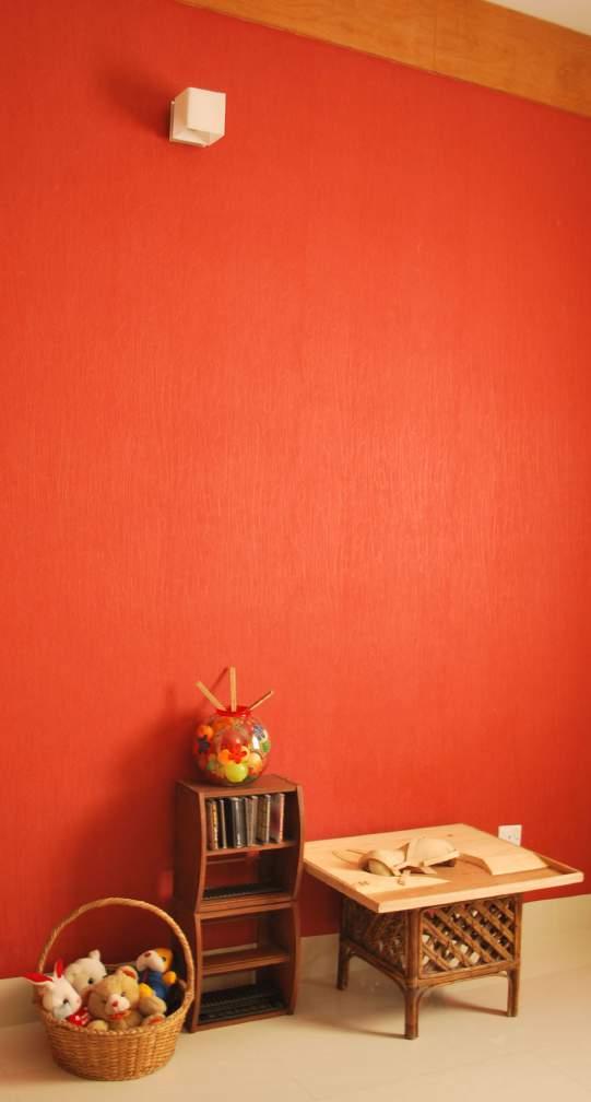
7.1
As mentioned before, the developer responsible for building construction Union Holdings Ltd had listed suppliers and subcontractors who carry out their construction work. After completion of design, drawing and specification, materials & fixtures were explored from the listed sources. The suppliers submitted their product catalogue and price lists for consideration(Fig 88a)The architect also accompanied the client to conduct a physical survey to stores exploring options for tiles, sanitary & kitchen fixtures, lighting fittings and fixtures. Samples of veneer and laminated board were collected to evaluate its compatibility in actual de-sign space. The task became a long process of experimentation, comparison and copromisation between choice and price. Most of the materials were ordered from the listed suppliers. Once the choice was made, the developer arranged the delivery on site. In case of special materials that couldn’t be procured from en-listed providers, the architect organised order and delivery from other sources upon approval from the cli-ent. For example, the red textured wall paper for the 2nd Bedroom (Fig 88b) was collected from Tamanna Interiors who wasn’t included in the developer’s list.
8.1
Most of the construction work i.e. woodwork, tiles and marble layout, Aluminium and glass fittings, paint and polish work was conducted by the subcontractors appointed by Union Holdins Ltd. They were appoint-ed based on their skills and previous work history with Union Holdings. The architect had to communicate the design with the contractors and supervise their work. Architect organised special technicians if the de-veloper wasn’t able to provide one. In the above mentioned example, the architect hired technicians to mount the red textured wall paper on the 2nd bedroom upon agreement with the client.
64
Identification of available procurement methods and assessment of relevance and application to the project.
Selection process for appropriately qualified contractors is in accordance with procurement method and project contract.
Fig 88a: Brochure and pricelist for tiles
Fig 88b: Red textured wall paper in 2nd Bedroom
MRS. MOZIRON AHMED ON PLOT NO. 234,BLOCK NO. B, BASHUNDHARA
OF EAST-WEST PROPERTY DEVELOPMENT (Pvt.) LTD.(C.S.KHOTIAN NO. 283,
KHATIAN NO. 654, DAG NO.1427 & 1435) MOUZA- JOARSHAHARA,
DHAKA CANTONMENT, DISTRICT-DHAKA.
BONOCHAYA INTERIOR PROJECT 5
PC 9.7 : Knowledge
of legal and regulatory requirements and obligations in regard to architectural practice, practice management and registration as an architect.
The apartment building was situated in a prime location of Dhaka city. The plan of the building had to be authorised by Rajuk. A DIT sheet ( Fig89) was submitted to Rajuk for approval. The sheet contained floor plans, elevation and section drawings compling with the building codes.
The building was 6 storied and the total floor area was 2268 sqm. According to BNBC code, if the building is more than 4 storied and the total floor area is greater than 1000 sqm, The architect involved has to be a full member of IAB ( Institute of Architects Bangladesh).
PC 9.6 : Knowledge and application of professional ethics and ethical practices in respect to practice management and provision of professional service.
The original design had balconies attached to Masterbed,3rd bed, living space an kitchen. The client want-ed to remove them and include the space inside the rooms. The design was already authorised by Rajuk. The exterior facade was preserved as it was in original design including the allocated openings. But the in-terior was modified to expand room spaces. In this case, it was the only option to fulfill the client’s demand remianing within legal boundaries.
65 0.45m SCALE 100 FRONT ELEVATION EAST) LAY-OUT PLAN N 7.62m W D E R O A D SCALE: 1:200 Stair Underground LIFT S/T Water tank SECTION A-A' SCALE: 1:100 0.91m TYPICAL FLOOR PLAN N SCALE: 1:100 TOILET 5'-0"X7'-0" LIFT LIVING 3.66mX3.66m BED 3.05mX5.18m KITCHEN 1.83mX2.64m TOILET 1.83mX1.52m BED 3.05mX3.96m VER 2.01mX0.91m LIVING 3.66mX4.68m KITCHEN 1.83mX3.76m TOILET 1.83mX1.52m 1.83mX1.83m 0.92mX2.77m VER 3.66mX1.07m A' GROUND FLOOR PLAN N 7.62M W I D E R O A D SCALE: 1:100 LIFT 1.83mX1.83m TOILET 1.52mX1.22m STAIR 4.95mX2.51m SUBSTATION GENERATOR ROOM 5.56mX2.74m RECPTION 5.51mX1.9m DINING 5.21mX4.22m MBED 4.27mX4.27m BED 4.67mX3.02m DINING 4.88mX3.75m MBED 3.66mX4.84m TOILET 1.22mX2.29m VER 2.74mX1.04m TOILET 1.83mX1.52m BED 3.05mX3.05m LIVING 3.66mX4.68m KITCHEN 1.83mX3.76m TOILET 1.22mX2.29m VER 2.74mX1.04m TOILET 1.83mX1.28m VER 1.52mX1.07m TOILET 1.83mX1.52m MBED 4.27mX4.27m BED 4.67mX3.27m TOILET 1.83mX1.52m 3.05mX3.05m VER 1.77mX1.07m DINING 5.21mX4.47m BED VER 2.21mX1.52m DRIVER REST ROOM 3.79mX2.64m 1.5m 3.0m 3.0m 3.0m 3.0m 3.0m 3.0m 0.45m 2.59m 3RD FLOOR LEVEL 2ND FLOOR LEVEL ROOF LEVEL 1ST FLOOR LEVEL PLINTH LEVEL ROAD LEVEL 0.45m 0.45m 18.29m 1.25m 1.25m 15.79m 1.5m 23.94m 2.0m 27.44m PROPERTY LINE 23.94m 15.79m MRS. MOZIRON AHMED P.S.
S.A.
FOR
PROJECT
PROPOSED 6(SIX)
PROJECT ARCHITECT'S NAME AND SIGNATURE DRAWING TITLE : RAJUK SHEET AutoCad By:Md. Aktar Hossain LAND OWNER'S NAME & SIGNATURE SCALE AS SHOWN DATE LAND AREA :- = 501.87 SQ.M. GROUND FLOOR COVERED AREA= 378.01 SQ.M. 1ST TO 5TH FLOOR AREA(378.01m x5) = 1890.05 SQ.M. TOTAL AREA Including Stair & Lift = 2268.06 SQ.M. 304.19 Sq.M CAR PARKING 15.79m 1.25m 1.25m 18.29m 27.44m 2.0m 23.94m PROPERTY LINE 1.5m 0.45m 0.45m PROPERTY LINE UP PROPOSED BUILDING A' 7.62 m WIDE ROAD THE PLOT N SITE PLAN SCALE 64'-0" 18.29 m WIDE ROAD 7.62 m WIDE ROAD 18.29 m WIDE ROAD 234 235 233 232 231 230 229 228221 220 219 218 217 216 215 214 236 237 238 239 240 241 242 243 213 212 211 210 209 208 207 206 PROPERTY LINE
STORIED RESIDENTIAL BUILDING
Fig 89: Draft of DIT sheet for Rajuk appoval