11 minute read
Methodology
1. Iterative coding and scriptwriting for new software development
First Version
Discrete Design v1.0 was developed in Java programming language and used functionality from the ‘flexible software sketchbook’ Processing by Ben Fry and Casey Reas. Operating within a Cartesian grid, the software generates a voxel space from an imported volume and serialises these voxels according to different criteria, including structural requirements, porosity and transparency. Users can control both the overall mass of the object at the macro-scale and material organisation at micro-scale. Different line fragments inside one voxel can be imported as basic units. A combinatorial algorithm then substitutes each of the voxels in the 3D space for one unit or another and picks the one that best matches the local requirements. The rotation of the units is automated, ensuring connectivity between the end of one line fragment and the start of the next. This ensures the creation of a continuous line that can be printed by a robot equipped with a polymer extruder.
Discrete Design v1.0 (16) approximates the curvilinear morphology of the volume to be filled in an orthogonal manner. First, the Vitra Panton Chair (1967) was modelled in Autodesk Maya. It was then imported into the software as a manifold-mesh object with no self-intersections. A voxel space was generated from its bounding box, with voxels falling outside the mesh being removed. The size of the voxels is modifiable within the range of toolpathsegment lengths, printed with specific extrusion equipment. The software executes a basic finite element analysis that abstracts structural data from the imported mesh to determine the type of cell to be used in each voxel. Cells are then instantiated along the voxel space and allocated in response to local compression and tension levels. Two types of cells were used for the first prototype generated using Discrete Design v1.0: a flat cell that generates high-density areas of the material and a 3D cell that supports the flat cells in areas with low density. The former is used in those areas with higher stress, while the latter is used where the stress values are low and a more fragile line fragment is sufficient.
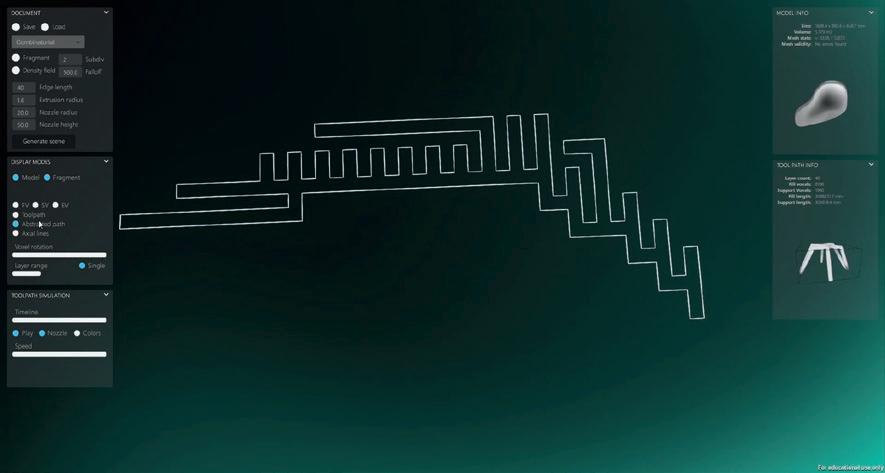
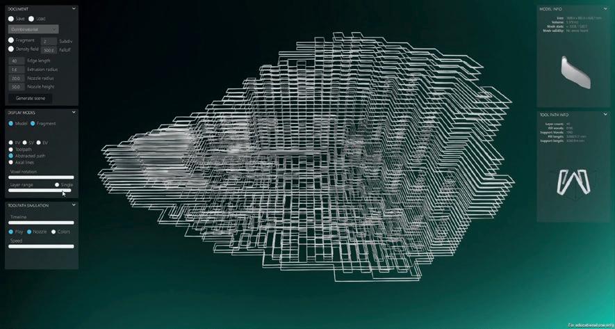
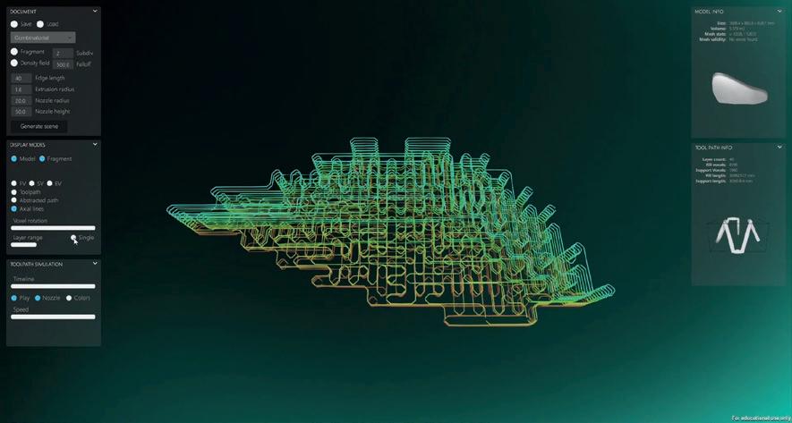
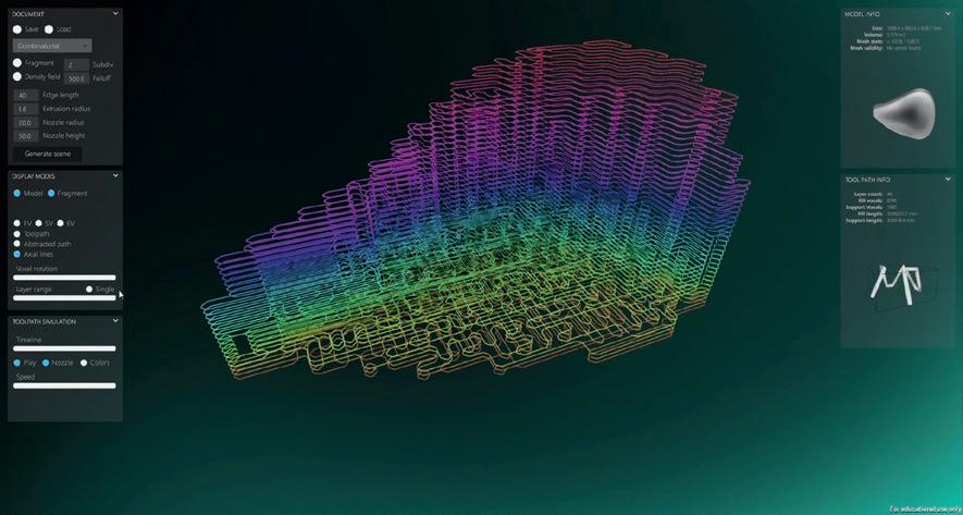
Voxels are grouped by their vertical coordinates into layers of a given height (17). Flat-cell areas are grouped in sublayers and indexed from bottom up to fill the total voxel height. Each layer and sublayer are represented as an undirected graph. Their centres are associated with vertices and their orthogonally adjacent cells with edges of the graph. The disconnected graphs connect through the discarded edges. Subsequently, a Hamiltonian path is used to create a sequence of connected cells where each vertex is visited only once (18–21). The cells rotate in two dimensions until an end point of the toolpath fragment connects to the open edge of the previous cell in the sequence. The principal direction of stress is abstracted from the finite element method (FEM) to be assigned as the preferred orientation of the cell when multiple rotations are possible.
Each toolpath fragment of the idealised path is further adjusted to avoid collisions and other possible issues when printing. When neighbouring cells contain overlapping edges they offset inwards by half of the extrusion thickness, which
prevents collisions with the extruded material; it also serves as a boundary between the described segments. Overhanging fragments are extended towards the previous supported cells to compensate cantilevers. This implies overriding these cells and computing a reconnection with the remaining fragments in the toolpath.
Once the toolpath is computed, a vertex sequence is exported as a csv file. Discrete Design v1.0 does not offer a bridge between this step and the code that the robot executes but exports this csv file, which will then be imported in Rhinoceros Grasshopper to generate a continuous poly-line. The robot program is generated through the Robots plugin created by Vicente Soler.
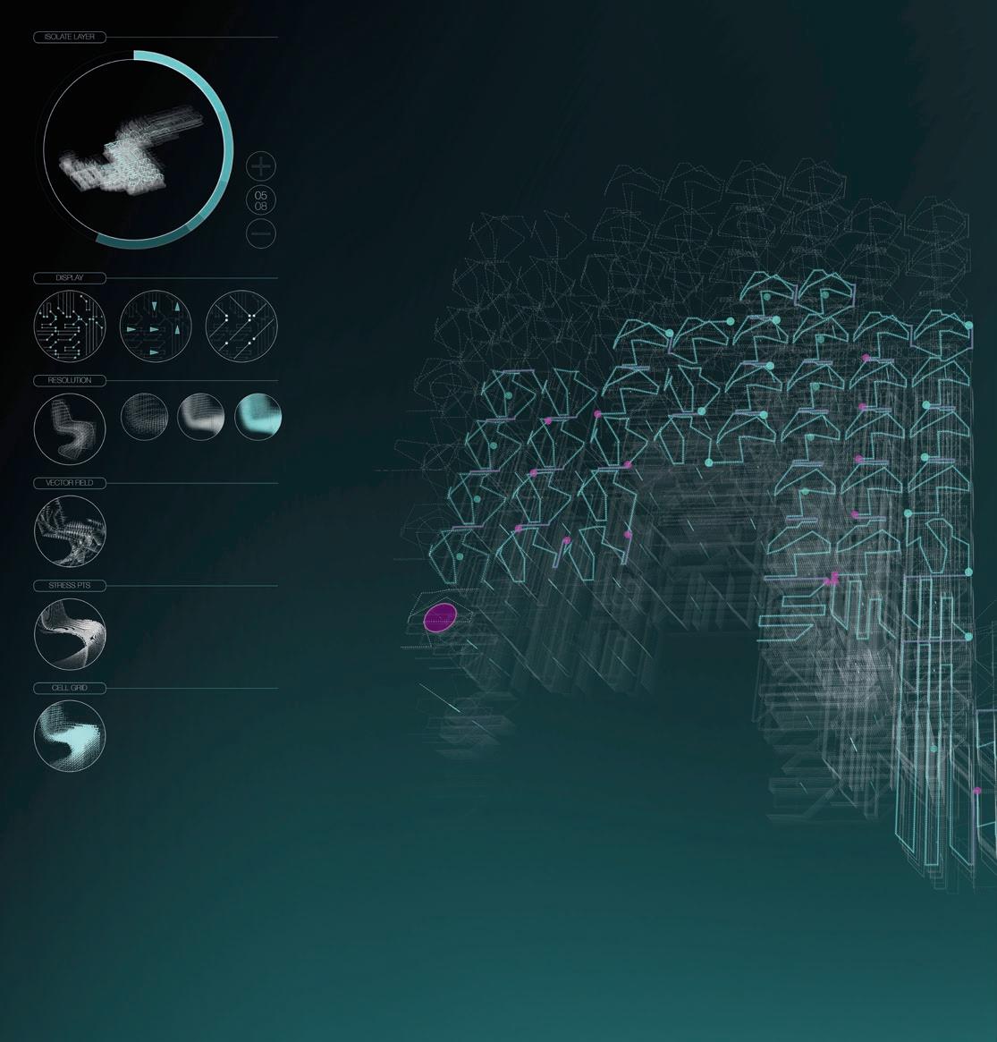
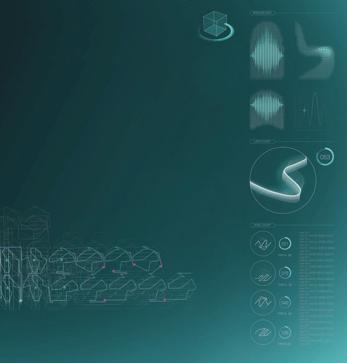
16 (overleaf) Discrete Design v1.0 screenshot showing line-fragment distribution in VoxelChair v1.0. The left side is dedicated to visualisation modes, allowing particular layers to be isolated (top), and shows information about the line fragments. The right side depicts the object’s mass balance, computed layers and located line fragments (top to bottom).
17
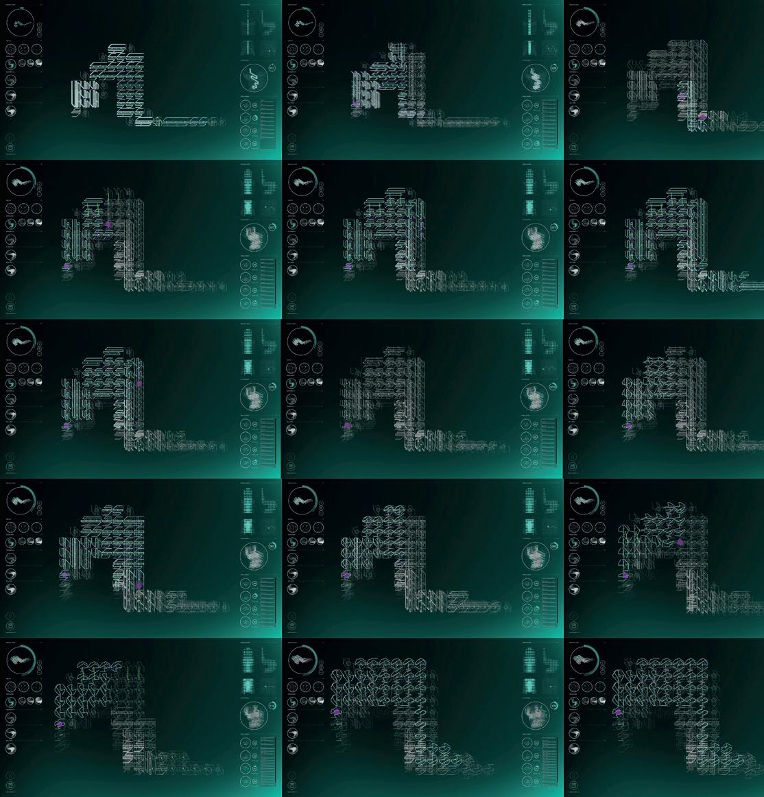
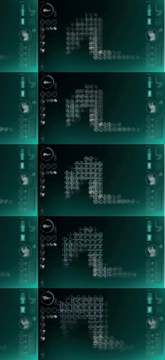
17 Sequence of layer-bylayer calculations for VoxelChair v1.0 in Discrete Design v1.0.
18
19
18 Visualisation of the Hamiltonian path, which visits all vertices once, in one isolated layer found in the connected subgraphs. This is used to arrange the line fragments in the printing process and guarantees continuity in the extrusion.
20
21
19–21 The Hamiltonian path in Ogonori.
Second Version
Discrete Design v2.0 was fully rewritten in C# using Unity as a framework, with the aim to streamline the generation of the robot program. Although this version does not yet create a full robot program requiring functionality from Robots for Grasshopper and the use of the plugin after the csv file is generated, it integrates 3D-printing constraints and information such as flow rate, speed and retraction points into the generated csv. This allows for a much more streamlined translation into the robot program, without needing to specify those values in the Grasshopper plugin.
The limitations of the equipment can be readily imported as constraints in the second version of the software. As the extruder moves up and down, the geometry of the nozzle is imported to check for possible intersections with the printed segments. To avoid sagging, segments extruded in a downward direction are printed at lower speeds. Extrusion speed is slightly higher in segments printed upwards, to keep them in tension. A waiting time is also introduced at the end of those segments, as well as a sucking motion effectuated by the extruder controller while the material is cooling down.
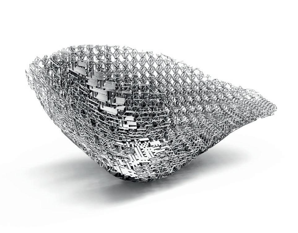
To test out the new functionalities of Discrete Design v2.0, a physical prototype was produced in the shape of a chaise longue, inspired by Charles and Ray Eames’ La Chaise for Vitra (1948). The prototype Ogonori evidenced the streamlined communication between the design generation and robotic 3D printing (14). Discrete Design v2.0 approximates the line fragments in the voxels to the mesh face, achieving a smoother surface that increases comfort and mitigates the 'voxel look' of the object (22). Both prototypes were printed at Nagami Design, a robotic manufacturing company based in Avila, Spain, founded by Manuel and Miguel Angel Jiménez GarcÍa and Ignacio Viguera Ochoa. To accelerate the printing process, especially for line fragments printed in the air, the Nagami team added a vortex tube to the extruder’s cooling system that pours compressed air to the end of the nozzle. This helps lower the temperature and accelerates the cooling process. This system is only activated when material is extruded in the air. Higher-density cells can be extruded at the maximum speed when most of their segments are supported by lower layers with no need for cooling. The signal for when to activate/deactivate the cooling system is embedded in the code of each line fragment in Discrete Design v2.0, whereas v1.0 requires external actuation by a switch.
22
22 Digital visualisation of Ogonori, generated with Discrete Design v2.0 and rendered in Keyshot.
2. Iterative digital prototyping of line fragments
Line fragments were designed and iteratively tested using robotic 3D-printed prototypes. Initial iterations of the Discrete Design software focused on the creation of continuous toolpaths for robotic plastic extrusion. A limited number of discrete units are printed to test the process, which are then instantiated and connected to generate a ready-to-print continuous line. Once a fragment’s printability has been confirmed in all possible directions, the piece is included in the software to be instantiated throughout the voxel space. This way, all possible errors inherent in the constraints of spatial 3D printing are tested beforehand to preclude the possibility of unexpected deformations in later, more crucial, stages of the large-scale print. Multiple toolpath variations can, therefore, be created to fill any given bounding box or volumetric object. This allows for differentiated material density in response to structural conditions, while a combinatorial algorithm allows for differentiated material distribution. Material density and direction can be locally controlled by changing the scale and orientation of the fragments, producing a gradual differentiation of the strength of the object across its volume (23).
Although this software was initially created for 3D printing, its functionality could easily be used for other manufacturing methods within a Discrete Design methodology, such as the aggregation of bent metal bars or building blocks made out of timber sheets or cast in concrete. As long as a limited number of discrete units is used, and those units fit a voxelspace, later iterations of Discrete Design software could be developed to establish the syntax for their connectivity.
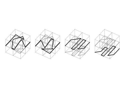
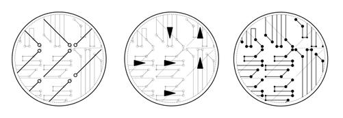
23 Four line fragments from VoxelChair v1.0. From left to right, the first two show the air-printed lines alternatively distributed in subsequent layer groups where stress levels are low. The next two fill those voxels in areas with higher stress levels to create a better structural integrity. 24 Different modes of visualisation to be activated/deactivated in the Discrete Design software, showing the different properties of the line fragments. From left to right: Line fragment end points, directions, fragment vertices (large circles indicate upper vertices, while small circles indicate lower vertices).
25
26
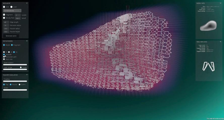
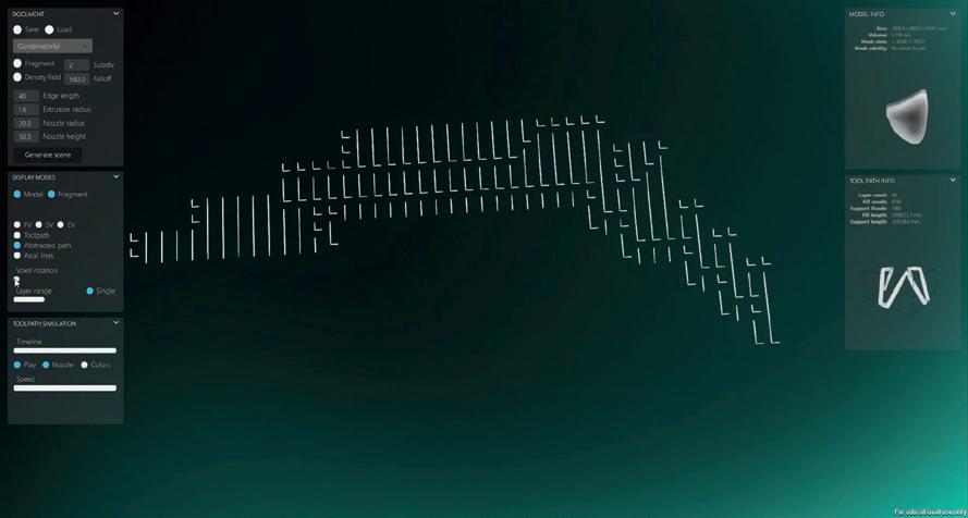
25 Discrete Design v2.0 screenshot showing the line fragment distribution in Ogonori. Left, from top to bottom: File setup, allowing printing and geometrical factors to be changed; visualisation modes displaying different features of the object and the computed toolpath; toolpath simulation timeline. Information about the base model and the line fragment in use is depicted on the right. 26 Screenshot showing minimum spanning trees establishing a subgraph with the connectivity of the cells. The elements are ordered in the same direction (corner or straight).
3. Iterative physical testing using robotically 3D-printed prototypes to serialise and anticipate errors
In its various iterative steps, the research involved both digital prototyping and physical testing. Discrete Design v1.0 was tested in the creation of VoxelChair v1.0, which was commissioned in 2016 by the Centre Pompidou in Paris. The chair uses two different fragment types that are assembled into a continuous 2.36-km toolpath. The Grasshopper plugin, Robots, converts the abstracted program into manufacturer-specific language and then outputs it to the robot controller. Nagami’s ABB IRB 4600 robot was used to create the VoxelChair v1.0 prototype, and the pellet extruder – proprietary technology of Nagami – was specifically developed for this project. VoxelChair v1.0 established the computational principles necessary to aggregate linear elements in response to structural parameters.
Discrete Design v2.0 was first used for the creation of the Ogonori chaise longue. The same two types of line fragments were used for this prototype, however, those in boundary voxels were deformed to better match the curvature of the object. This demonstrated the added functionality of the software. As most necessary printing information is already embedded in the output of Discrete Design v2.0, Robots for Grasshopper serves as a mere intermediary to translate the csv file into a robot program that can be imported into the controller of Nagami’s ABB robots.
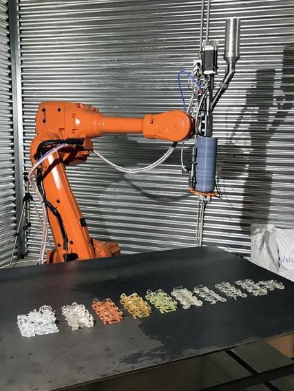
27 Robotically 3D-printed samples, realised at Nagami, with different types of PLA, colourant and tones.
27
28
29 30
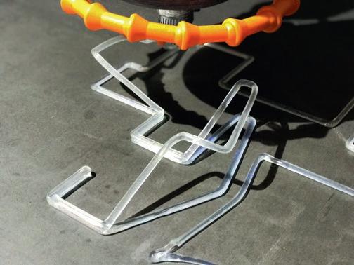
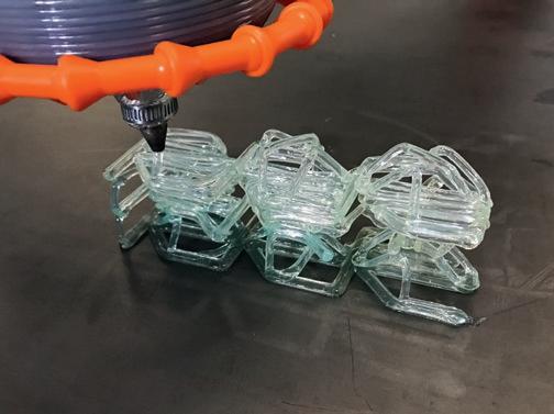
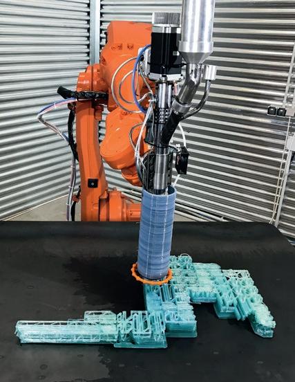
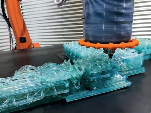
28–9 PLA robotic-extrusion process at Nagami. The chair is printed in two halves, rotated 90 degrees and assembled with the same PLA and colourant used in the printing process. 30–1 Robotically 3D-printed samples, realised at Nagami, with different types of PLA, colourant and tones.
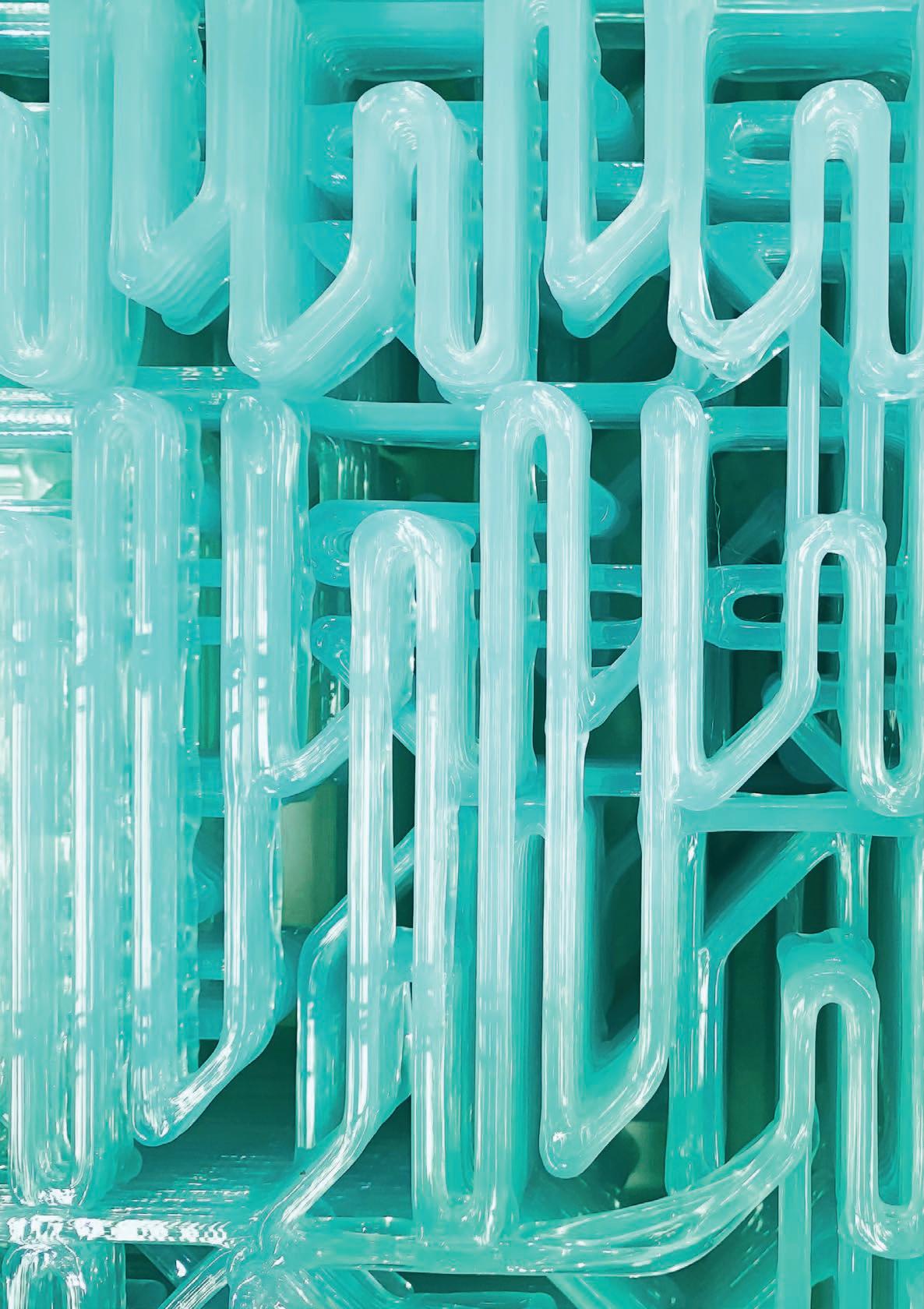
32 Detail of PLA roboticextrusion process at Nagami.
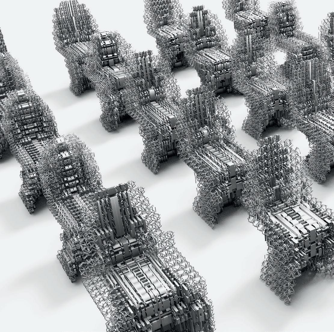
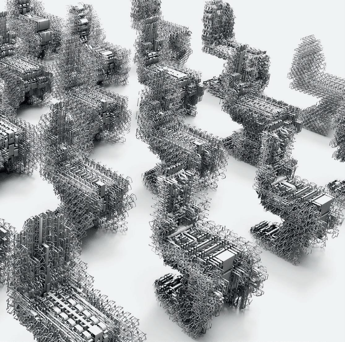
33 Collection of robotically printed VoxelChair variations, configuring a landscape of different material organisations.
4. Reviews, lectures and seminars to ensure continuous peer feedback and knowledge exchange
The project has formed a catalyst for cross-faculty knowledge sharing and discussion within UCL and other institutions. An informal dialogue with researchers from The Bartlett’s Architectural Design and Architectural Computation courses was initiated to explore how digital design and fabrication strategies can be further integrated and developed in a series of related IT and engineering disciplines. Discrete Design software has been especially relevant in the research that Design Computation Lab has developed within UCL, serving as inspiration for a large variety of projects focusing on robotic additive manufacturing using discrete methods. The evolution of the software has been undoubtedly linked to the experience gained in such projects. Much of the functionality added to v2.0 collects technical requirements observed in the creation of robotically printed prototypes, which the lab has generated over the last five years of 3D-printing research.
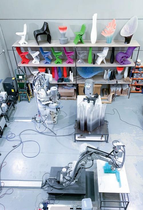
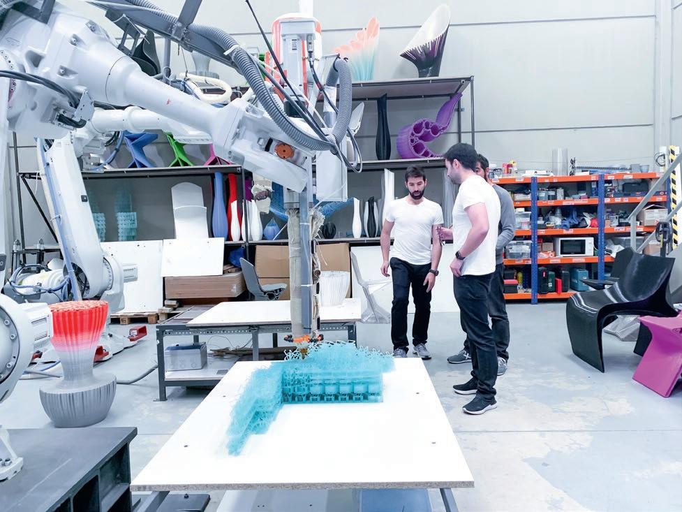
34–5 PLA robotic extrusion of VoxelChair v1.0, created for the Philadelphia Museum of Art. The same ABB 4600 robot was used, painted white, along with Nagami’s third-generation extruder for robotic plastic extrusion.
35


