11 minute read
ENGINEERING
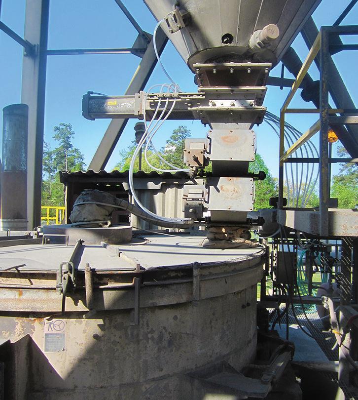
PHOTO: JENIKE & JOHANSON INC.

GETTING BIOMASS ASH TO FLOW AGAIN
A project at Dominion Energy’s Altavista, Hopewell and Southampton power stations solved the facilities’ biomass fly ash handling challenges. BY JAYANT KHAMBEKAR, JOSH MARION AND RIAD DANDAN
Modern power stations are increasingly looking at renewable fuel sources such as biomass. While using biomass as fuel provides several benefits, the combustion ash can be particularly challenging to handle compared to the typical ash from coal combustion. Biomass fly ash can be highly cohesive and frictional, and can set up in the silo like concrete. To solve ongoing issues related to fly ash, three power stations operated by Dominion Energy followed a systematic and scientific approach to design biomass fly ash handling systems that provide reliable flow.
Dominion Energy is one of the major power generation companies in the U.S. At Dominion, focus is always on progress and using the latest scientific technology to do things in an improved manner. Recognizing the need of time, Dominion converted three of its existing coal-fired power stations in Virginia—the Altavista, Hopewell and Southampton Power Stations—to 100%
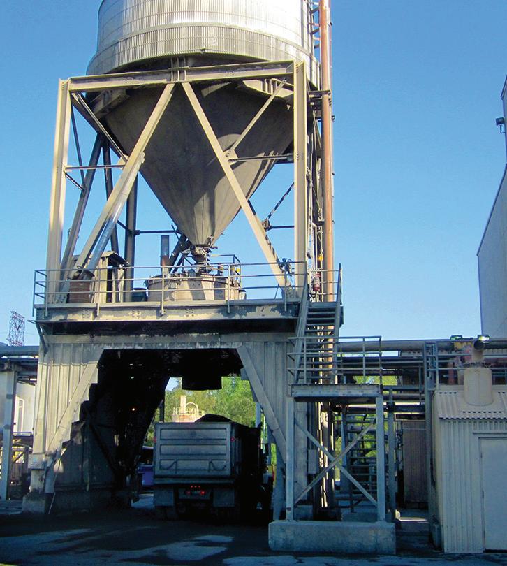
Figure 1: Original fly ash unloading silo (top); arrangement below the silo outlet (bottom). PHOTO: JENIKE & JOHANSON INC.
biomass fuel. These facilities use wood chips and waste wood as fuel and each can produce up to 51 MW of electricity. The three stations have similar biomass handling systems. At each of them, fly ash generated is first collected in ash hoppers and is then pneumatically conveyed into an ash unloading silo.
The ash is fed into the unloading silo at temperatures between 250 and 300 degrees Fahrenheit and then sits in the silo until a truck arrives at the site. The storage time without discharge can vary from four hours up to two days.
The original ash unloading silo’s intended use was for coal fly ash. It consisted of a 26-foot diameter cylinder section, followed by a conical hopper (made from carbon steel—no liner) that converged at 36 degrees
from vertical to a 14-inch OD outlet. Below the silo was a slide gate and a double flap valve that discharged ash into a “conditioner” before it was unloaded into trucks. The desired fly ash discharge rate from the silo was about 6,000 pounds per hour.
As a result of its temperature, consolidation pressure in the silo, storage time without discharge, ash moisture content and the presence of reagents, the ash frequently set up in the silo. It also arched and ratholed over the silo outlet. This had been a persistent problem at all three power stations. Dominion needed to rely on air cannons and air lances to break the arches and restart flow. While these flow aids provided some help, they were not able to resolve the issue. These ash flow problems were resulting in frequent manual intervention, inconsistent flow to the ash conditioner and long waiting times for truck unloading.
In addition, during periods of high fuel moisture, the unburned carbon content of fly ash increased. Coupled with the air leaks to the baghouse hoppers and pneumatic conveying system of ash, extremely high-temperature (greater than 1,000 degrees F) clinkers would form in the baghouse hoppers and the fly ash silos, further complicating the material buildup issue.
Dominion recognized the need for a scientific approach to solve this problem, and in 2015, contracted Jenike & Johanson Inc. to address the flow problems in the ash unloading silos at these three stations. Riad Dandan, balance of plant systems engineer from Dominion’s headquarters in Richmond, Virginia, was involved throughout the project and was instrumental in identifying the problems and providing project direction, as were numerous personnel from the three power stations.
Bulk Solids Handling Fundamentals
Before presenting analysis of the problems with the fly ash silo, it is helpful to understand some of the fundamentals of material flow in a silo. There are two primary flow patterns that can develop in a silo during discharge: funnel flow and mass flow.
In funnel flow, an active flow channel forms above the hopper outlet, with stagnant material at the periphery. As the level of material in the silo decreases, material from stagnant regions may or may not slide into the flowing channel, depending on the bulk solid’s cohesive strength. When the bulk solid has sufficient cohesive strength, the stagnant material does not slide into the flow channel, which results in the formation of a stable rathole. In addition to flow stoppages that occur as a consequence of ratholing, funnel flow results in a first-in, last-out flow sequence, and allows flooding if fine powders such as the biomass fly ash are filled into a rathole, or if a rathole collapses.
In mass flow, the material is in motion whenever any is withdrawn from the hopper. Material from the center, as well as the periphery, moves toward the outlet. Mass flow hoppers provide a first-in, firstout flow sequence, eliminate stagnant material and provide a steady discharge with a consistent bulk density and flow that is uniform and well controlled. Requirements for achieving mass flow include sizing the outlet large enough to prevent arching and ensuring the hopper walls have sufficiently low (material/surface boundary) friction and are steep enough to achieve flow at the walls.
It is critical to note that the flow pattern in a hopper is strongly influenced by the feeder below the hopper. Ultimately, a feeder should accomplish the following: 1. Provide reliable and uninterrupted flow of material from the silo above. 2. Control discharge rate from a silo, achieving the required rate while preventing flooding. 3. Remove material from the entire cross section of the hopper outlet to avoid interfering with mass flow in the silo above.
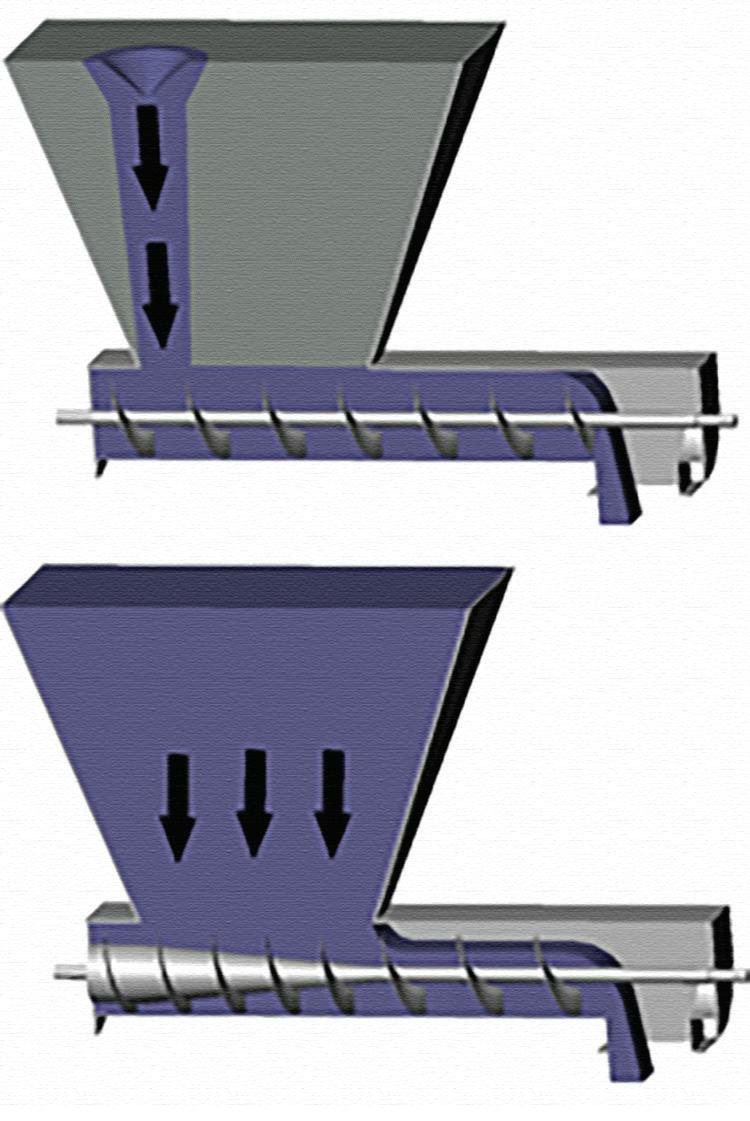
If a screw feeder has constant pitch (Figure 2, top image), the first pitch will fill up and subsequent pitches will be unable to accept more material. As a result, material will flow through one small preferential channel above the first pitch, creating the potential for ratholing, increasing arching potential and decreasing the maximum flow rate for fine powders. If the screw feeder is properly designed with increasing capacity in the direction of flow (Figure 2, bottom image), it will remove material from the entire cross section of the hopper, and the flow channel will open up.
Specializing in Pneumatic & Electric Vibratory Solutions

Cleveland Made Quality Since 1923

Alleviate material flow issues & achieve maximum clean out in:

Ingredient Bins & Hoppers Surge Hoppers Load Out Bins
We offer direct support for your solution with products designed and manufactured with quality and dependability in mind. We are committed to stock & availability.
How Fast Can We Deliver For You?
clevelandvibrator.com • (216) 241-7157
Trust the Team With 95+ Years of Experience Behind Them.
Flow Problems Review, Testing and Analysis
Once contracted by Dominion, as a first step in the process, Jenike conducted a site visit to fully understand the ash flow problems and possible root causes. Dandan and Jayant Khambekar of Jenike visited all three power stations to review the handling systems and identify small differences between these three stations. Based on the review of the existing ash handling, flow issues and possible root causes, Jenike suggested a test program to Dominion.
The fly ash flow behavior was sensitive to the “fresh” condition of sample. In other words, if fly ash was tested after shipping the sample to Jenike’s laboratory (a few days after being produced), the flow behavior would not be the same as obtained by testing a fresh sample of the fly ash. Additionally, the fly ash handled at each of the three stations had different flow properties because of differences in fuel sources, and variation in ash moisture content. Furthermore, ammonia content in the ash could also vary. Dominion and Jenike discussed the possible concerns and correspondingly developed a test program that covered the risks.
Accordingly, Jenike conducted the testing on-site at at each power station, using fresh samples of biomass fly ash and Jenike’s
Figure 2: Constant pitch screw feeder (top), mass flow screw feeder (bottom). PHOTO: JENIKE & JOHANSON INC.
special on-site tester. It was also important to characterize effect of variation in moisture content of fly ash as well as ammonia content. To this end, some testing was also done at Jenike’s laboratory in Tyngsboro, Massachusetts, at representative fly ash temperatures to study the effect of variation in moisture and ammonia contents. Samples from all three stations were tested to identify the worst-case flow behavior so that a common silo arrangement could be developed to work for all three stations.
During this testing, various wall surfaces were evaluated to determine the most suitable wall surface from a reliable material flow perspective. These wall surfaces included 304 stainless steel sheet with a #2B cold-rolled finish, 304 stainless steel sheet with a #4 180 grit finish, WellerCLAD Hypol, and Tivar HOT UHMW-HDPE liner.
Test results showed that the biomass fly ash samples were cohesive and frictional. As moisture content of fly ash increased, the materials became significantly more cohesive and prone to buildup and flow stoppages. The materials also got very frictional with increases of ammonia content. Based on the test results, the existing conical hopper walls, at 36 degrees from vertical, were not steep and smooth enough for material to flow along them. Thus, funnel flow discharge was occurring in these silos. Also, the 14-inch-diameter outlet was significantly undersized to prevent ratholing for continuous flow and after storage at rest. It also was not preventing flow stoppages due to cohesive arching at higher moisture contents, or storage at rest for all moisture contents. The test data correctly predicted and validated that frequent flow stoppages would occur with these silos.


Corrective Plan
Dominion and Jenike discussed the test results and analysis to determine the most appropriate path forward. Dandan worked with Dominion’s team to discuss possibilities for modification of the existing ash silo arrangement versus a new silo arrangement. Given the challenging flow behavior of the biomass fly ash, Dominion’s storage capacity requirements and tight layout constraints, it was not an easy decision for Dominion. Ultimately, Dominion decided to install a new silo arrangement, provided that it could be located in the same footprint as the existing silo.
Using the results of the biomass fly ash testing as the basis, Jenike developed a design of the new silo arrangement common for all three power stations. Given the challenging flow behavior and other constraints, the arrangement recommended utilizing two silos with 11-foot, 6-inch-diameter cylinder sections. Each silo consisted of a conical hopper, a short vertical section and a transition hopper. Based on the test results, 304 stainless steel sheet with a #4 180 grit finish was selected as the liner, in order to promote material flow along the hopper walls. A screw feeder with twin 18-inch-diameter augers was designed below the silo outlet, according to the mass-flow screw design shown in the above image. This promoted activation of
New silo arrangement installed at Dominion’s power stations PHOTO: JENIKE & JOHANSON INC.
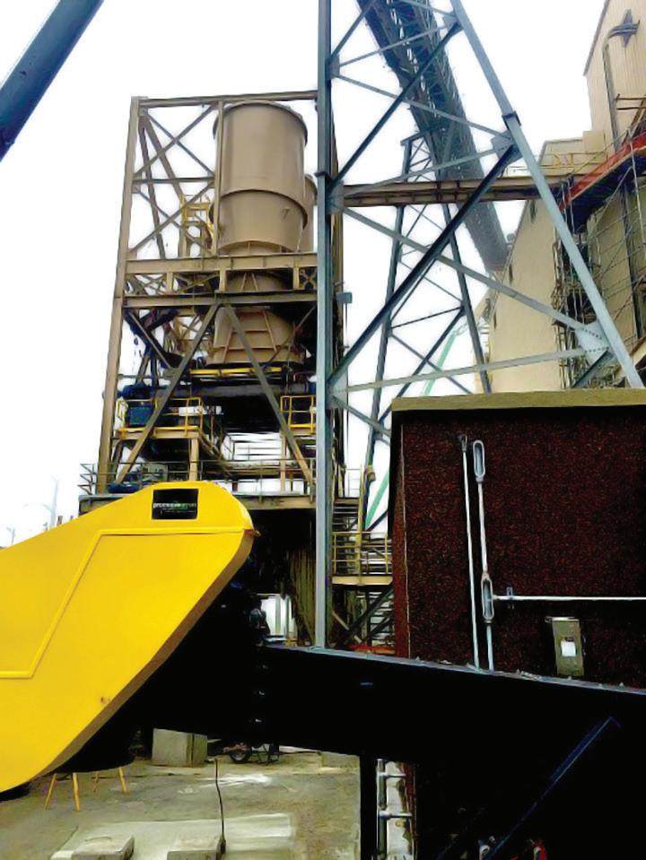
the entire hopper outlet to allow uniform discharge. A slide-gate arrangement was provided above the screw feeder for maintenance purposes. The upstream arrangement above the silos included a common drag chain conveyor to fill both silos. The downstream arrangement below the screw feeder included a chute and rotary airlock to discharge material into the ash conditioner.
Based on the silo and the feeder design provided by Jenike, ProcessBarron developed the fabrication plan and managed the construction activities, supplied the equipment and oversaw the installation. Once the equipment was fully installed and operational, Dominion conducted test runs that went smoothly.
Performance Results
After nearly five years of operation, the silos and feeders designed by Jenike have been working very well at all three power stations. Before the modifications, fly ash would set up like concrete in these silos such that at times the stations needed to use large plastic containers for ash storage, and the silo discharge locations needed to be manned to assist material discharge. With the new silo design, all these troubles are gone, and the three power stations are getting their biomass fly ash to flow again.
Dominion’s emphasis on progress and on using the latest scientific technology resulted in a successful outcome. This positive experience can also help other power stations using biomass as their fuel and dealing with the challenges of ash handling.
Contact: Jayant Khambekar Senior Consultant, Jenike & Johanson Inc. jayant@jenike.com 281-921-1998


