
(INSIDE COVER PAGE TO ALWAYS INCLUDE CONTENT BELOW)

(INSIDE COVER PAGE TO ALWAYS INCLUDE CONTENT BELOW)
Beaumont is on the traditional territory of Treaty 6 First Nations and the homeland of the Métis. We acknowledge all those who share a deep connection with this land. The City of Beaumont respects the histories, languages, and cultures of all of Canada’s First Peoples, whether they be of First Nation, Métis, or Inuit descent, and appreciates that their presence continues to enrich Canada’s vibrant communities.
FIRST ISSUE
3 February 2023 Schematic Stage Report
Prepared by Reviewed by Approved By
Janessa Chin
Yusra Rameen
SECOND ISSUE
Juan Upegui
Michael Nishiyama
6 April 2023 30% Report
Joshua Maxwell
Prepared by Reviewed by Approved By
Juan Upegui
Janessa Chin
Yusra Rameen
THIRD ISSUE
Juan Upegui
Michael Nishiyama
Blair Raymond
9 June 2023 60% Report
Joshua Maxwell
Prepared by Reviewed by Approved By
Juan Upegui
Janessa Chin
Yusra Rameen
Juan Upegui
Michael Nishiyama
Joshua Maxwell
FOURTH ISSUE
24 July 2023 90% Report
Prepared by Reviewed by Approved By
Juan Upegui
Janessa Chin
Yusra Rameen
FIFTH ISSUE
Juan Upegui
Michael Nishiyama Joshua Maxwell
17 August 2023 100% Report
Prepared by Reviewed by Approved By
Juan Upegui
Michael Nishiyama
Janessa Chin
Yusra Rameen
Juan Upegui
Michael Nishiyama
Joshua Maxwell
Vaughn Shears
Authored by: (Signature)
Janessa Chin, E.I.T. Municipal Engineering EIT (Water Distribution System)
Authored by: (Signature)
Yusra Rameen, E.I.T. Designer EIT, Municipal Engineering (Stormwater System)
Authored by: _______________________________________ (Signature) ____________________________ (Stamp)
Juan Upegui, M.Eng., P.Eng. Water Resources Engineer (Water Distribution System / Wastewater System)
Authored by: (Signature) (Stamp)
Michael Nishiyama, M.A.Sc., P.Eng.
Project Manager, Water Resources (Stormwater System)
Model
Reviewed by:
Ariane Sauter, P.Eng.
Team Lead, Water Resources
(Signature) (Stamp)
(Water Distribution System / Wastewater System Model Review)
Model
Reviewed by:
Blair Raymond, M.Sc., P.Eng.
Water Resources Engineer
(Stormwater System Model Review)
(Signature) (Stamp)
Report
Reviewed by: _______________________________________
(Signature) ____________________________ (Stamp)
Joshua Maxwell, M.Sc., P.Eng., PMP.
Team Lead, Water Resources, Municipal Engineering, Infrastructure
(Report Review / Water System Operational Items)
(Report Approval1)
WSP Canada Inc. prepared this report solely for the use of the intended recipient, CITY OF BEAUMONT, in accordance with the professional services agreement. The intended recipient is solely responsible for the disclosure of any information contained in this report. The content and opinions contained in the present report are based on the observations and/or information available to WSP Canada Inc. at the time of preparation. If a third party makes use of, relies on, or makes decisions in accordance with this report, said third party is solely responsible for such use, reliance or decisions. WSP Canada Inc. does not accept responsibility for damages, if any, suffered by any third party as a result of decisions made or actions taken by said third party based on this report. This limitations statement is considered an integral part of this report.
The original of this digital file will be conserved by WSP Canada Inc. for a period of not less than 10 years. As the digital file transmitted to the intended recipient is no longer under the control of WSP Canada Inc., its integrity cannot be assured. As such, WSP Canada Inc. does not guarantee any modifications made to this digital file subsequent to its transmission to the intended recipient.
1 Approval of this document is an administrative function indicating readiness for release and does not impart legal liability on the Approver for any technical content contained herein. Technical accuracy and fit-for-purpose of this content is obtained through the review process. The Approver shall ensure the applicable review process has occurred prior to signing the document.
The City of Beaumont (the City) engaged WSP Canada Inc. (WSP) to complete the Utilities & Storm Water Management Master Plan (U&SWMP). This study assessed the existing systems and provided servicing schemes for the water, wastewater and stormwater systems for the ultimate development horizon (2048 and beyond).
Beaumont is a city in the southeast portion of the Edmonton Metropolitan Region, bordered by Leduc County in the west, south and east ends and the City of Edmonton in the north. Ground elevations in Beaumont range from 749.8 metres in the central east (St. Vital neighbourhood area) and 701.7 metres in the northwest. Drainage is generally from the southeast/east to the west. The principal watercourses in the area include the LeBlanc Canal (southeast end) and Irvine Creek (north end).
The majority of land in Beaumont is currently zoned for Agricultural Holding District (about 55 percent of the municipality), followed by residential districts (about 42 percent). The remaining land comprises light industrial and commercial districts. According to the latest federal census, Beaumont has a population of 20,888 people with a private dwelling county of 6,950 units (average household size of 3.0 people per unit).
The existing agricultural lands comprise most of the growth areas in Beaumont, although some development will also occur within the previous municipal boundary. Future land uses, and population projections beyond 2048 were available for this study. The ultimate projected population in Beaumont is 96,553 people, with a target greenfield density of 35 dwelling units per net residential hectare. Aspirational intensification within the existing areas of Beaumont is ten percent. The City provided a development staging forecast covering five-year periods from 2023 to 2048 and beyond. The projected population was distributed among all development stages to analyze the water and wastewater systems.
Various background information and data were reviewed as part of this study, including planning documents, past studies related to the water, wastewater and stormwater systems, drawings, and facilities data. Information was also collected regarding the Capital Region Southwest Water Services Commission (CRSWSC) and the Alberta Capital Region Wastewater Commission (ACRWC), major stakeholders in the City’s water and wastewater systems, respectively.
The City’s water distribution system includes over 90 kilometres of water mains and two pumphouses and reservoirs: Main Pumphouse and Reservoir (MPR) and the St. Vital Pumphouse and Reservoir (SVPR). Water is supplied to the City’s MPR reservoir via a 400-millimetre transmission main from the CRSWSC system. The CRSWSC master plan outlines a secondary feed to Beaumont in five to ten years and the transfer of some infrastructure ownership (including the Beaumont supply water main) to EPCOR. The fill rate to the MPR reservoir is based on water demands projected by the City.
The MPR and SVPR are configured with setpoints such that the resultant operating pressures are about the same when operating in standalone mode. The existing reservoirs provide a total storage capacity of 17,273 cubic metres. The MPR includes five identical pumps with a total combined capacity of 275 L/s. The SVPR includes two identical distribution pumps (combined capacity of 222 L/s) and an engine-driven fire pump (220 L/s). The current process control narrative allows MPR and SVPR to operate in a lead arrangement (both online) or standalone mode. Filling of the SVPR reservoir generally occurs overnight.
The City’s water network primarily comprises 200-millimetre diameter pipe but range between 150 to 400 millimetres. Most water mains were installed in 2000-2009 and consist of polyvinyl chloride (PVC). Just over 17 percent of the water mains comprise asbestos cement pipes.
Recent average consumption rates in Beaumont indicate about 190 l/c/d. Current water consumption is about 1.53 million cubic metres, representing a 2.5 percent increase from the previous year.
The existing water distribution system was assessed based on a combination of the City of Beaumont General Design Standards and guidelines from provincial or nearby municipalities. Reservoir storage needs were determined based on the CRSWSC requirements and the Fire Underwriters Survey (2020)
The hydraulic model from a previous study was reactivated and updated to represent the assumed existing conditions. The model was verified and reviewed internally and with the City to ensure it represented the system accurately. Water demands in the model were estimated based on population densities calculated in the previous study, as finer and more recent census data was unavailable. The existing system was assessed under several scenarios, including the MPR, the SVPR in standalone mode, or the MPR in lead. Water demand scenarios included the average day demand (ADD), maximum day demand (MDD) plus fire flow, and peak hour demand (PHD). A fill scenario was also reviewed but found to no longer govern the design. The adopted design criteria required the City’s system to operate between 350-550 kPa under ADD and PHD scenarios and as low as 140 kPa under the MDD plus fire flow scenario. Pressures greater than 280 kPa were considered acceptable, as other municipalities use this value as the lower limit (i.e., Edmonton). Fire flow requirements in Beaumont range from 100 L/s for single and low-density residential and as high as 270 L/s for commercial and multi-family or high-density residential.
The model results indicated system pressures ranged between 320 and 663 kPa for the ADD scenario and 310 and 650 kPa for the PHD scenario. As expected, system pressures were about the same when the MPR or SVPR operated in standalone mode and together. Low-lying areas in Beaumont experience system pressures over 550 kPa, the maximum allowable pressure for fixtures (National Research Council Canada, 2020). Contrarily, the higher ground areas in Beaumont, namely the central-northeast portion, experience system pressures in the range of 310 kPa. Under the MDD plus fire flow scenario, various locations were identified as unable to supply the required fire flow. These are primarily in areas with a dead-end water main or water main with pipe diameters smaller than currently allowed in the City’s General Design Standards.
A cursory review of a new feed from the CRSWSC to the SVPR was completed. The CRSWSC documents indicated that the existing regional infrastructure could supply the SVPR reservoir (Associated Engineering Ltd., 2020). While there is capacity in the regional system, the fill rate to Beaumont cannot be increased beyond 1.8 times the projected water consumption for the community due to CRSWSC policies.
The existing MPR has known electrical service deficiencies, requiring the diesel generator to run when more than three pumps are needed. The MPR pumps cannot meet current MDD plus fire flow demands in standalone mode, even if all five are assumed to be running. There is currently a 101 L/s deficit at the MPR. The SVPR pumps, on the other hand, can meet the current range of demands, although the current PHD flows are near the limit of both distribution pumps.
The City’s system currently can store 17,273 cubic metres of potable water in its reservoirs. The current reservoir storage requirement is 12,260 cubic metres, meaning there is a surplus of about 4,650 cubic metres.
Improvements to the existing system included installing pressure-reducing valves at the homes or building services or establishing different pressure zones in the City’s system via inline pressure-reducing valves. The pressure-reducing valves at homes or building services were decided to be challenging for implementation in existing developed areas. These valves, however, can be specified in engineering design drawings for new developments with relative ease. Implementing pressure zones in the City is recommended to be reviewed further. The Centre-Ville Area Redevelopment Plan (CARP) recommended that the Centre-Ville area (generally) is isolated from the rest of the system and includes a local booster station that would allow pressures in the area to be increased and support higher-density redevelopment.
Fire flow issues were recommended to be addressed as neighbourhood renewal occurs and require some review of adequate fire hydrant spacing. Electrical service at the MPR should be addressed immediately due to aged and deficient infrastructure. Pumping capacity upgrades should consider requirements for the next ten years.
Three options for the ultimate water servicing concept were developed and analyzed. These are described in the following:
Option 1: MPR or SVPR servicing the Main Pressure Zone and two future pumphouses and reservoirs servicing the Northwest Pressure Zone.
Option 2: MPR or SVPR servicing the Main Pressure Zone and one future pumphouse and reservoir servicing the Northwest Pressure Zone.
Option 3: MPR or SVPR servicing the entirety of Beaumont.
The concepts are generally compatible with the existing inter-municipal plan, which outlines a secondary feed to another City reservoir from the EPCOR system.
All options were reviewed with the City in a workshop, and Option 2 was recommended as the preferred servicing scheme. The reasons included accounting for feedback from the City, striking a balance between the number of reservoirs and pumphouses, staging considerations and maximizing the use of existing infrastructure. The recommended option includes additional storage cells at the SVPR, which would allow this facility to meet Beaumont’s water needs for the near future. The Northwest Pumphouse and Reservoir (future facility) would generally service the low-lying lands in Beaumont (west and northwest areas) and areas not forecasted to develop until the 2043-2047 horizon. Implementing separate pressure zones in Beaumont should be reviewed and refined further. Analysis of the ultimate servicing scheme and development staging showed some improvement in the operating system pressures, but some areas remained outside the desired operating range (350-550 kPa). The ultimate system model also indicated the proposed system would supply the required fire flows in future growth areas. An implementation plan outlining City, CRSWSC and development servicing infrastructure was provided, including cost estimates for each development horizon.
High-level operational system recommendations were also provided for the water system. This task included a review of the SCADA software, equipment, communications, and standards. A brief review of water neutrality (balancing water consumption with generation) and water infrastructure security (surveillance, cybersecurity, etc.) was completed. The City’s water utility rate is briefly reviewed.
The City’s wastewater system includes over 85 kilometres of gravity sewers, including several trunk sewers and storage pipes. Wastewater servicing for the Beaumont is provided via the South East
Regional Trunk Sewer (SERTS) South, owned and operated by the Alberta Capital Region Wastewater Commission (ACRWC). A pump station near Range Road 244 pumps wastewater from a larger pipe in the SERTS South to the original trunk sewer (525-millimetre sewer). Wastewater from Beaumont is ultimately discharged to the EPCOR South East Sanitary Sewer (SESS) and treated at the Gold Bar Wastewater Treatment Plant in Edmonton. The ACRWC anticipates completing the SERTS South twinning from the existing pump station to approximately Irvine Creek in the west over the next five to ten years.
A review of wastewater flow data from the ACRWC indicated a peaking factor as high as two, with dry weather flows ranging between 10 and 80 L/s. Average wastewater flows from Beaumont are about 135 L/p/d, indicating a return ratio of about 70 percent (i.e., 70 percent of the water consumed is returned as wastewater).
The City’s wastewater system primarily comprises 200-millimetre sewers and range between 150 and 2,100 millimetres. The larger pipes are storage pipes. Wastewater sewers were constructed mainly in 1990-1999 and 2010-2019. Most of the City’s sewers comprise polyvinyl chloride (PVC) pipe, although vitrified clay tile (VCT) pipe is a major component (about 18 percent). There are known weeping tile connections to the City’s systems in the core area of Beaumont. These connections can worsen flow conditions in the City’s system (inflow and infiltration). Recent CCTV inspection efforts by the City have revealed several obstructions in sewers.
The existing wastewater system was assessed based on a combination of the City of Beaumont General Design Standards and provincial guidelines.
The hydraulic model from a previous study was reactivated and updated to represent the assumed existing conditions. The model was verified and reviewed internally to ensure it represented the system accurately. Wastewater loadings in the model were estimated based on the same population-based approach in the water model and previously calibrated model parameters. The model calibration had to be corrected due to issues in upgrading the City’s wastewater model. The existing system was assessed under dry weather flow and two wet weather flow conditions (as outlined by the ACRWC) based on sewer capacity utilization and depth of hydraulic grade relative to ground.
The model results indicated no issues during dry weather flow conditions, but it highlighted some shallow sewers in the City’s system. The City’s system was also analyzed under the 5-year, 24-hour rainfall event. A few sewers were shown as surcharging. Surcharging is even more significant in the 25-year, 24-hour rainfall event, with four sewer stretches identified as concerning: the ACRWC’s SERTS South, Trunk Sewer 4 and two local sewers.
Proposed improvements included the completion of the SERTS South twinning and three other City projects. Model results for the improved system show concerns are significantly mitigated. As the only wastewater discharge point for Beaumont, the SERTS South twinning is critical. Inflow and infiltration mitigation work should be undertaken before implementing any other City system improvements. Mitigation work may reduce the extent or eliminate the need for improvements.
An ultimate servicing concept was developed for all development horizons. The concept deviates from the current inter-municipal plan for servicing the Northwest Annexation Lands, although it is feasible (i.e., did not require deepening infrastructure). The Elan Lift Station is still required but would experience higher inflows in the ultimate buildout. The appropriate stakeholders should be engaged and updated about this
change. The ultimate system model indicated that the City’s wastewater system would not require additional improvements for the ultimate development horizon beyond those proposed in previous stages. The ultimate servicing concept requires upsizing the SERTS South trunk sewer to accommodate the required wastewater flows without excessive surcharging. An implementation plan outlining City and development servicing infrastructure was provided. An order of magnitude cost estimate was also completed for the infrastructure required during each development horizon.
The City’s storm system includes approximately 75 km of storm sewer, ranging from 150 mm to 1800 mm in diameter. The storm sewers consist mainly of PVC pipe, with some concrete and HDPE pipes and one corrugated metal pipe (CMP). Most of the City’s storm sewers were constructed after 2000, with some constructed as early as 1976. The City has 39 SWMFs, consisting of 37 wet ponds and two dry ponds, and has an underground storage tank located in Centre-Ville. The LeBlanc Canal was constructed in the 1920s and has been upgraded on multiple occasions, and currently functions as a major drainage feature for the City of Beaumont, with the majority of the SWMFs within the City discharging to the canal.
A stormwater model was developed in PCSWMM to assess the City’s stormwater infrastructure. The hydraulic network was modelled using a dual drainage approach to capture major and minor system performance. The City’s GIS dataset, design drawings, and planning documents were reviewed and used to develop the stormwater model. The model was constructed by importing the City’s GIS data into PCSWMM and making further modifications to refine the imported assets and rectify data gaps. The 5year 4-hour Chicago Distribution storm was simulated to assess the minor system, the 100-year 24-hour Huff Distribution was simulated to assess the major system, and two additional Huff Distributions design storms, 5-year 24-hour and 25-year 24-hour, were also simulated to assess the major stormwater system over a shorter return period. The City’s stormwater system was evaluated based on the design criteria presented in the City of Beaumont General Design Standards. Potential areas of concern were identified for further review and discussion with the City. WSP engaged in multiple workshops with the City to better understand the system functionality and discuss potential system improvements. The following major concerns were identified:
• LeBlanc Canal: LeBlanc Canal functions effectively but has potential flooding concerns at culvert crossings. The constriction of flow caused by the culverts limits the conveyance and causes backups creating potential issues. However, these issues do not present a major risk to persons or property
• North lands: This area is very flat, with several wet, low-lying areas contributing to localized ponding issues. The area lacks effective drainage causing flooding concerns.
• Public works yard: The public works yard is used for snow collection and experiences springtime flooding due to snow melt.
• West lands: Local RV property in the southeast corner of the west annexation lands experience flooding due to its flat and low location. The peak flooding depth reaches approximately 0.75 metres from the bottom of the existing channel along the western extents of the RV lands, posing a potential risk of flooding within the property.
• Parkview SWMF: Parkview SWMF has flooding concerns, with water overflowing towards the Main reservoir cells, potentially leading to infiltration. The flap gate in the downstream culvert is believed to be installed backwards, which is obstructing flow and resulting in the pond overtopping.
Potential system improvements were recommended to address system deficiencies identified in the existing system The following recommendations were provided for the major system issues:
• LeBlanc Canal: It was recommended that the canal be maintained as portions of the canal are overgrown and potentially contain significant amounts of sediment. In the long term, future developments such as the Southlands will reduce the overall peak flow. Redevelopment within the City, such as Centreville, and low-impact development (LID) projects will also have a marginal impact on reducing peak flow rates. No major upgrades to the canal are recommended. However, culverts should be inspected periodically, and deteriorated culverts should be replaced. Additionally, it was recommended that Beaumont initiate a monitoring program for the canal. Monitoring will assist in the confirmation of the canal’s performance and provide data for future flow assessments. A preliminary cost estimate was provided for flow monitoring.
• North lands: Flooding issues in Northlands will resolve with the ultimate buildout. However, interim solutions were recommended. These included maintaining existing channels to ensure efficient conveyance and a detailed review of discharge from the upstream Coloniale SWMFs to ensure appropriate operational procedures are in place.
• Public works land: The public works yard outlet should be inspected for proper discharge, and the ditch should be maintained to ensure effective conveyance. Additionally, the operation of the snow depot should be reviewed to use the onsite storm facility to reduce peak runoff, especially if downstream conditions are wet. To ensure the public work minor system is operational, it was recommended to connect the public works system to the minor system located in the Dansereau neighbourhood. The Dansereau Meadows Central SWMF and the immediate upstream system have spare capacity for additional flows. A preliminary cost estimate was provided for this option.
• West lands: There are limited immediate solutions for the RV lands flooding. However, issues will be resolved with the phased development of the Elan area. Interim recommendations included regular maintenance of channels and culverts, including cleaning downstream channels and upstream culverts across HWY 625. Onsite grading or berming could also potentially alleviate flooding issues. However, this option requires detailed analysis and site review.
• Parkview SWMF: The flap gate should be removed to provide an outlet for the SWMF. Additionally, enhancing downstream grading from Parkview and around the reservoir cells may potentially eliminate ponding in those areas. A preliminary cost estimate was provided for this option.
A high-level review of several LID methodologies is presented, including bioretention, rain gardens, bioswales, rainwater tree trenches, soil cells, green roofs, rainwater harvesting, infiltration chambers, permeable pavement, and stormwater landscaping. Preliminary LID locations were identified and discussed based on the existing system issues.
The existing hydraulic model was updated using future land use mapping and planning documents to construct the ultimate growth scenario model. This primarily consisted of new growth within the undeveloped areas of the City limits, with some redevelopment in Centre-Ville at the core of Beaumont. The ultimate drainage concept presented major stormwater infrastructure (SWMFs and interconnecting trunks) and followed existing planning documents wherever possible. Preliminary storage requirements were estimated for SWMFs if the data was unavailable in existing planning documents, and a preliminary drainage concept was developed for the Northwest Annexation lands and Southwest Annexation lands, which were not covered under any ASPs or NSRs. Servicing concepts were then developed for each development horizon An implementation plan outlining City and development servicing infrastructure was
provided. An order of magnitude cost estimate was also completed for the infrastructure required during each development horizon.
Figure 4 Existing Conditions (Assumed)
Figure 5 Ultimate Land Use Plan
Figure 6 Neighborhoods
Figure 7 Development Staging Forecast
Figure 8 Existing Water Distribution System - Water Main Size
Figure 9 Existing Water Distribution System - Water Main Material
Figure 10 Existing Water Distribution System - Water Main Installation Period
Figure 11 Historical Water Consumption (2012-2022)
Figure 12 Existing Water Distribution System - ADD Main Pressure
Figure 13 Existing Water Distribution System - ADD Vital Pressure
Figure 14 Existing Water Distribution System - ADD Main & Vital Pressure
Figure 15 Existing Water Distribution System - Fill Main Pressure
Figure 16 Existing Water Distribution System - PHD Main Pressure
Figure 17 Existing Water Distribution System - PHD Vital Pressure
Figure 18 Existing Water Distribution System - PHD Main & Vital Pressure
Figure 19 Existing Water Distribution System - MDD+FF Main Available Flow
Figure 20 Existing Water Distribution System - MDD+FF Vital Available Flow
Figure 21 Existing Water Distribution System - MDD+FF Main & Vital Available Flow
Figure 22 Existing Water Distribution System - Hydrant Coverage
Figure 23 Ultimate Water Distribution System - Option 1 Servicing Concept
Figure 24 Ultimate Water Distribution System - Option 2 Servicing Concept
Figure 25 Ultimate Water Distribution System - Option 3 Servicing Concept
Figure 26 Ultimate Water Distribution System - Pressure Zones
Figure 27 Proposed CRSWSC Transmission Main Extension to St. Vital Reservoir
Figure 28 Ultimate Water Distribution System - Option 2 - ADD Main & Northwest Pressure
Figure 29 Ultimate Water Distribution System - Option 2 - PHD Main & Northwest Pressure
Figure 30 Ultimate Water Distribution System - Option 2 - MDD+FF Main Vital & Northwest Available Flow
Figure 31 Option 2 Water Distribution System - 2028-2032 Buildout - ADD Main Pressure
Figure 32 Option 2 Water Distribution System - 2028-2032 Buildout - PHD Main Pressure
Figure 33 Option 2 Water Distribution System - 2028-2032 Buildout - MDD+FF Main & Vital Available Flow
Figure 34 Projected Reservoir Needs (2022 to Full Buildout)
Figure 35 Option 2 Water Distribution System - Water Main Staging
Figure 36 Option 2 Water Distribution System - 2023-2027 Buildout
Figure 37 Option 2 Water Distribution System - 2028-2032 Buildout
Figure 38 Option 2 Water Distribution System - 2033-2037 Buildout
Figure 39 Option 2 Water Distribution System - 2038-2042 Buildout
Figure 40 Option 2 Water Distribution System - 2043-2047 Buildout
Figure 41 Option 2 Water Distribution System - 2048+ Buildout
Figure 42 Existing Wastewater System - Sewer Size
Figure 43 Wastewater Patterns During Dry Weather in 2022
Figure 44 Existing Wastewater System - Sewer Material
Figure 45 Existing Wastewater System - Sewer Installation Period
Figure 46 Existing Wastewater System - Calcite Buildup / Other Obstructions
Figure 47 Existing Wastewater System - Weeping Tile Connections
Figure 48 Existing Wastewater System - Major Features
Figure 49 Flow Monitor Locations
Figure 50 Site 1 Results Comparison
Figure 51 Site 2 Results Comparison
Figure 52 Site 3 Results Comparison
Figure 53 Site 4 Results Comparison
Figure 54 Site 5 Results Comparison
Figure 55 Site ACRWC Results Comparison
Figure 56 Existing Wastewater System - Dry Weather Flow Results
Figure 57 Existing Wastewater System - 5-Year 24-Hour Huff Storm Results
Figure 58 Existing Wastewater System - 25-Year 24-Hour Huff Storm Results
Figure 59 Existing Wastewater System - Proposed Upgrades
Figure 60 Existing Wastewater System with Proposed Upgrades - 25-Year 24-Hour Huff Storm Results
Figure 61 Ultimate Wastewater System - Servicing Concept
Figure 62 Ultimate Wastewater System - Catchment Connections
Figure 63 Weekday and Weekend Diurnal Patterns (2022 Data)
Figure 64 Ultimate Wastewater System without Upgrades - 25-Year 24-Hour Huff Storm Results
Figure 65 Ultimate Wastewater System - Proposed Upgrades
Figure 66 Ultimate Wastewater System with Upgrades - 25-Year 24-Hour Huff Storm Results
Figure 67 Ultimate Wastewater System - Wastewater Sewer Staging
Figure 68 Ultimate Wastewater System - 2023-2027 Buildout
Figure 69 Ultimate Wastewater System - 2028-2032 Buildout
Figure 70 Ultimate Wastewater System - 2033-2037 Buildout
Figure 71 Ultimate Wastewater System - 2038-2042 Buildout
Figure 72 Ultimate Wastewater System - 2042-2047 Buildout
Figure 73 Ultimate Wastewater System - 2048+ Buildout
Figure 74 Existing Stormwater System - Storm Sewer Size
Figure 75 Existing Stormwater System - Storm Sewer Material
Figure 76 Existing Stormwater System - Storm Sewer Installation Period
Figure 77 Existing Stormwater System - Existing Model Subcatchment Areas By Land Use
Figure 78 Existing Stormwater System - Minor System 5-Year 4-Hour Storm Event
Figure 85 Existing Stormwater System - Major System 100-Year 24-Hour Storm Event
Figure 86 Storm System Issues and Potential LID Locations
Figure 87 S-UPG-1 - Connection from Public Works Yard to Dansereau
Figure 88 West Lands RV Park Channel Flooding
Figure 89 Ultimate Stormwater Growth Model
Figure 90 Ultimate Stormwater System - 2023-2027 Buildout
Figure 91 Ultimate Stormwater System - 2028-2032 Buildout
Figure 92 Ultimate Stormwater System - 2033-2037 Buildout
Figure 93 Ultimate Stormwater System - 2038-2042 Buildout
Figure 94 Ultimate Stormwater System - 2043-2047 Buildout
Figure 95 Ultimate Stormwater System - 2048+ Buildout
A Population Projections
B Excerpts from Planning Documents
C Excerpts from CRSWSC Documents
D Existing System Review
E Model Migration, Verification and Updates Memorandum
F Water Distribution System - System Operations Review - Meeting Minutes
G Reservoir Needs Calculations
H Master Plan Workshop - Presentation and Meeting Minutes
I Ultimate System Options Analysis Memorandum
J Wastewater Model Results - Simulated HGL
K Stormwater System Review
L LeBlanc Canal Profiles
M Cost Estimate Breakdown
N Capital Projects Review Workshop - Presentation and Meeting Minutes
The City of Beaumont (the City) engaged WSP Canada Inc. (WSP) to update its Utility Master Plan (water and wastewater systems) and develop a Stormwater Management Master Plan (SMMP), jointly known as the Utilities & Storm Water Management Master Plan (U&SWMP). Beaumont has recently experienced growth in all directions, and its expansion is expected to continue. New developments will increase demands or loadings in the existing water distribution, wastewater, and stormwater systems. As a result, the City identified the need for updating the water distribution and wastewater systems master plans and the creation of a SMMP to support the responsible and planned expansion of the community in the short and long term (5 and up to 25 years).
Past studies indicate that the City’s wastewater system has been assessed as early as the 1990s. In 1997, various residents experienced basement flooding leading to the Alberta Capital Region Wastewater Commission (ACRWC) initiating a series of studies to identify and address wastewater sewer backups in Beaumont. The studies found that sewer surcharging in the City’s system resulted from excessive inflow and infiltration in the core areas of Beaumont and provided mitigation alternatives. The Beaumont Flood Relief Alternatives (UMA Engineering Ltd., 2002) identified several wet weather storage/surcharge facilities and the provision of interconnections throughout the system to resolve basement flooding.
The City’s water and wastewater systems have been assessed since 2000 and updated approximately every decade. The Municipal Infrastructure Study (UMA Engineering Ltd., 2000), the Water and Sanitary Sewer Assessment (UMA Engineering Ltd., 2007) and the Water and Wastewater Systems: 2018 and Beyond (ISL Engineering and Land Services Ltd., 2018) assessed the City’s water and wastewater systems. These studies also provided servicing schemes to support growth in Beaumont.
The City’s stormwater infrastructure has historically been evaluated under separate cover. Portions of the stormwater system have been assessed since the 1990s, focusing on improving drainage in Beaumont and mitigating inflow and infiltration to the wastewater system. Records indicate that the 2009 Beaumont Stormwater Management Plan (Focus Corporation [now WSP], 2010) was the first comprehensive study assessing the City’s major stormwater management infrastructure (existing stormwater management facilities and LeBlanc Canal) and developing a future servicing scheme to support growth. The study was later updated in 2016. The City’s stormwater management facilities, conveyance infrastructure (i.e., sewers) and principal surface drainage features (i.e., LeBlanc Canal and other drainage courses) were subsequently analyzed in the Storm Sewer Model Development, Calibration and Performance Analysis (DHI Water and Environment Inc., 2016). None of the past studies comprehensively analyzed the Major and Minor drainage systems.
Beaumont is a city in the southeast portion of the Edmonton Metropolitan Region, bordered by Leduc County along the west, south and east sides and the City of Edmonton along the north. The City of Beaumont municipal boundary (Figure 1) roughly includes the area within Range Road (RR) 244 and RR 241, 0.8 kilometres south of Highway (HWY) 625 and 1.6 kilometres north of Township Road (TR) 510. The existing developed area in Beaumont is roughly bounded by TR 510, HWY 625, RR 243 and RR 241.
Figure 2 illustrates the ground topography in the area. The overall drainage direction is north/west towards Irvine Creek and, ultimately, Blackmud Creek. Ground elevations range between 749.8 metres in the central east and 701.7 metres in the northwest. Principal surface drainage features include Irvine Creek and LeBlanc Canal. Irvine Creek traverses the north end of Beaumont (north of TR 510) and drains east to west toward Blackmud Creek near HWY 2. The LeBlanc Canal is a tributary of Irvine Creek that originates south of HWY 625 and drains southeast to the northwest toward Irvine Creek.
Beaumont includes a mix of zonings, including residential, industrial, commercial, and agricultural developments, as shown in Figure 3. Over half of the lands are currently zoned for agricultural land uses, primarily comprising the lands annexed over the past decade. The agricultural lands are generally north of TR 510, west of RR 243 and south of HWY 625. The next major zoning comprises residential land uses, constituting lands in the core area of Beaumont. Table 1.1 provides a breakdown of the district zonings and their descriptions.
The main streets of Beaumont will undergo redevelopment to enhance the vibrancy and pedestrian orientation. Buildings shall be mixed-use on principal thoroughfares and single-use on secondary thoroughfares. Heritage resources shall be preserved or integrated into the streetscape.
Notes:
01 As described in City of Beaumont (2019a).
Beaumont has experienced significant growth recently. Provincial records indicate that the population in Beaumont is 21,918 as of 2022, making it the ninth fastest-growing municipality in Alberta (Government of Alberta, 2023). The latest federal census, which provides older data (completed in 2021), recorded a current population of 20,888 people, a private dwelling count of 6,950 units and an average household size of 3.0 people per unit (Statistics Canada, 2022). When completing the previous water and wastewater master plan, the population in Beaumont was 17,396 (Statistics Canada, 2016). Over the past six to seven years, Beaumont has experienced a population growth of about 4,500 people.
Population values from the time of completing the previous water and wastewater master plan were increased in this study to better match the current population value. The population adjustment was achieved by applying population generation factors calculated in ISL Engineering and Land Services Ltd. (2018). The adopted factors are summarized in Table 1.2. More recent population densities could not be calculated due to unavailable high-resolution census data providing values per neighbourhood.
Notes:
02 The medium-density residential approach was implemented where the unit count was unavailable (i.e., a single parcel). The net area was estimated from reviewing existing medium-density residential buildings in Beaumont and determined to generally comprise 30 percent of the parcel area.
Recent developments in core areas of Beaumont required using much smaller population generation factors (sometimes as low as one person per unit) to achieve a closer match between the census population values and values used in this study. The final population was calculated to be 22,571 for 2023, slightly over what was estimated by the provincial government and determined in the most recent federal census.
Figure 4 illustrates areas of Beaumont assumed to be currently developed. These areas were discussed with the City and agreed to be considered for assessing the existing systems. Areas assumed to be developed primarily included some Le Reve, Elan, Lakeview and Triomphe States stages and sporadic lots in Dansereau Meadows, Ruisseau, Montrose Estates, Place Chaleureuse and Beaumont Lakes neighbourhoods. The additional lots assumed to be developed would account for the slight overestimate in current population values.
The ultimate buildout land use plan is shown in Figure 5. This figure is a compilation of the available statutory plans (area structure plans or ASPs, neighbourhood structure plans or NSPs and outline plans) and the City’s Municipal Development Plan (MDP). The Northwest and Southwest Annexation Lands have no existing plans, so land uses for these areas were based on the City’s MDP. Future land uses primarily comprise residential land uses with commercial land uses along HWY 625 and the 50 Street corridor north of TR 510 and industrial land uses south of HWY 625 and around the City’s public works yard on TR 510.
Table 1.3 summarizes the current statutory plans guiding development within Beaumont. These plans apply to the corresponding neighbourhoods, as illustrated in Figure 6. NSPs are contained within the ASPs.
The future development staging forecast developed by the City is shown in Figure 7. The 2023 to 2027 stage includes at least three instances of ‘leapfrog development’ where development occurs away from existing developed areas, bypassing closer vacant parcels (i.e., earlier stages of Le Reve, an area in Elan adjacent to TR 505 and the western quarter section in the Southlands ASP). Similar patterns are observed in the later stages (between 2043 to 2047 and 2048 and beyond). Leapfrog development makes infrastructure staging challenging, requiring significant offsite infrastructure that will not be fully utilized for some time.
The future population targets were adopted from a spreadsheet provided by the City, containing updated population projections (low-, mid- and high-case scenarios) up to 2088. A printout of this spreadsheet is provided in Appendix A. Values in the spreadsheet were observed to be different from the Beaumont Growth Study 2014 Update (ISL Engineering and Land Services Ltd., 2014), indicating the forecast had been revised afterwards. For this study, the mid-case population projections in the spreadsheet were adopted. The spreadsheet had a base value of 15,400 for 2014 and projected 21,567 people for 2023 (similar to the existing population). The ultimate projected population for Beaumont is 96,553.
In addition to population projections, Beaumont is also subject to community development targets as a participating municipality of the Edmonton Metropolitan Region Board (EMRB). Greenfield density, centre and intensification targets specific to Beaumont are listed below (Edmonton Metropolitan Region Board, 2017):
01 a minimum greenfield residential density of 35 dwelling units per net residential hectare;
02 an aspirational intensification target comprising 10 percent of the built-up areas; and
03 an aspirational urban and sub-regional centre density target of 100 dwelling units per net residential hectare.
The adopted population value of 22,571 for 2023 had to be increased by 73,982 to achieve an ultimate population of 96,533. The future population in Beaumont was distributed according to the population generation factors listed in Table 1.2, based on service areas and the land use concept for the corresponding development stage. The average greenfield density achieved from the process was verified against the target minimum greenfield density set by the EMRB. Intensification in Beaumont was assumed to be 10 percent of the current population (or 2,257 people) and distributed throughout future residential and mixed land uses in Centre-Ville, as outlined in the future land use concept in ISL Engineering and Land Services Ltd. (2019). The remaining future population of 71,725 was distributed throughout the future development lands.
A breakdown of land consumption for each future development stage and corresponding incremental population values are provided in Table 1.4.
Notes:
01 The Centre-Ville intensification was assumed to occur during this development horizon. Some future development areas did not include detailed land use concepts that detailed circulation, public utility lots, parks, and other land uses that do not house population. So, a review of the land use
breakdown applied throughout existing statutory plans was completed to determine a suitable reduction factor for adjusting the gross residential area. A typical average ratio of low to medium-density residential was also calculated. The net residential area comprised about 62 percent of the gross area in future areas with existing statutory plans. Eight percent of the net residential area constituted medium-density residential land uses. The gross area reduction factor was applied to future developments in Coloniale Estates, Dansereau Meadows, the Northwest Annexation Lands and Ruisseau, which did not include detailed land use concepts. The only instance in which the medium density residential was calculated was at the Northwest Annexation Lands, which included primarily residential land uses but not a detailed breakdown. Implementing the gross area reduction factor and the low- to medium-density residential ratio showed that, on average, the EMRB minimum greenfield density of 35 dwelling units per net residential hectare was achieved.
The U&SWMP work generally included reviewing background information and data, analyzing the existing systems and developing future servicing concepts, including identifying staged infrastructure needs based on various development horizons. The calibration of the water and wastewater hydraulic models was not updated based on recent data.
The scope of work consisted of the following tasks:
· Collecting and reviewing background studies, information and data.
· Analyzing the existing water distribution, wastewater, and stormwater (Major and Minor) systems.
· Updating the water and wastewater models to represent the current conditions.
· Developing a dual drainage model representing the existing stormwater system.
· Assessing the capacity and identifying deficiencies in the existing systems, and recommending improvements.
· Reviewing and providing operational recommendations for the water distribution system.
· Developing servicing schemes to support future growth for the required development horizons.
· Developing a capital projects plan for implementing system upgrades and new infrastructure.
· Completing a report detailing the approach and findings, including figures of the existing and future systems assessment results and cost estimates for improvements.
Various background information and data were available for the study. This section outlines the planning documents, data and datasets, drawings and reports applicable to two or more of the City’s water distribution, wastewater and stormwater systems.
Table 2.1 provides a summary of past general studies.
TABLE 2.1 SUMMARY OF KEY STUDIES
STUDY YEAR DESCRIPTION
Beaumont Growth Study 2014 Update 2014 The Town of Beaumont engaged ISL Engineering and Land Services Ltd. to amend the 2012 Beaumont Growth Study. This document analyzed the current population, future population growth scenarios, future land requirements, serviceability of each system, future expansion areas, and development staging.
Our Zoning Blueprint: Beaumont Land Use Bylaw (Bylaw 944-19)
Our Complete Community Municipal Development Plan
Town of Beaumont Water and Sanitary Sewer Assessment
2019 This document outlines the land use districts within the City based on the principles of Beaumont’s Municipal Development Plan. The document sets out organized and sustainable development patterns under which all planning applications are reviewed.
2019 The City of Beaumont and Stantec Consulting Ltd. developed to guide development, services, and land use, outlining Beaumont’s relationship within the region. The document directs overall planning and engineering practices in Beaumont.
2007 The City of Beaumont retained UMA Engineering Ltd. to assess their water distribution and sanitary systems’ abilities to meet existing demands and provide a framework for future development (up to 2030). The existing wastewater system assessment indicated issues at the TR 510 wastewater trunk sewer and along the SERTS South under the 25-year, 24-design storm. Proposed improvements included storage along the trunk sewers or upsizing designed based on 2030 flows. Existing system issues in the water distribution system included deficient fire flow storage and availability in some areas. The ultimate servicing concept proposes a new reservoir and pumphouse (St. Vital), upsizing some water mains and a future water network.
City of Edmonton Future Land Development Drainage Planning Study
2017 The City of Edmonton engaged AECOM Canada Ltd. to develop stormwater and wastewater servicing concepts for focused growth areas, including the 2017 Beaumont Annexation lands. Specific to Beaumont, the recommended stormwater concept proposes servicing the northlands via the existing drainage courses and Irvine Creek. The wastewater concept proposes servicing these lands via a new trunk sewer part of the SESS.
ISL Engineering Water and Wastewater Systems: 2018 and Beyond
2018
The City of Beaumont retained ISL Engineering and Land Services Ltd. to update its water distribution and wastewater systems master plan. The study assessed the existing systems’ abilities to meet demands and provided a framework for future development, including the recently annexed lands. The existing water distribution system experienced high pressures in some areas, and fire flow availability was generally appropriate. The ultimate water distribution servicing concept proposed two new reservoirs in the west and northwest (separate pressure zone), pumping capacity upgrades at MPR and SVPR, and outlined the future water main network. The wastewater system assessment indicated issues along the SERTS South and two additional trunk sewers under the 25-year, 24-design storm. Conveyance improvements and completion of the SERTS South twinning were proposed. The ultimate servicing concept showed Beaumont serviced entirely by the SERTS South (requiring further upgrades) and identified five future lift stations.
Intermunicipal Planning Framework
2019
The City of Beaumont, Leduc County and the City of Edmonton engaged McElhanney Ltd. to develop an inter-municipal planning framework for areas of common interest to all parties. The study sets out future transportation, water distribution, wastewater and stormwater servicing concepts for the area and a collaboration framework. Specific to wastewater infrastructure, the City will share the costs of a trunk sewer that will service lands north of Irvine Creek within the City’s municipal boundary (part of SESS). Appendix B includes figure excerpts for the regional water and wastewater servicing concepts.
Offsite Levy Model User Guide
Town of Beaumont Offsite Levy Review
Town of Beaumont Financial Impact Model
City of Beaumont Amended Bylaw –1008-22 Off-site Levy
2017
2017
2017
The City of Beaumont retained CORVUS Business Advisors to outline the procedures related to the annual update of offsite levies.
The City of Beaumont retained CORVUS Business Advisors to outline the methodology and information used in establishing water, sanitary and transportation offsite levy rates and recommendations.
The Town of Beaumont retained CORVUS Business Advisors to complete a Financial Impact Model. This model allows the City to examine the financial impact of new development applications such as subdivisions, area structure plans, and more.
2022
In this document, the City updates the off-site levy bylaw. The document includes updated transportation, water, and sanitary infrastructure maps and defined off-site levy rates.
The following planning documents were reviewed and considered in this study:
· Coloniale Estates Area Structure Plan and Outline Plan (1990)
· Montalet Outline Plan (2002)
· Ruisseau Outline Plan (2013)
· Place Chaleureuse Outline Plan (2015)
· Dansereau Meadows Outline Plan (2017)
· Elan Area Structure Plan (2017)
· Elan Neighbourhood Structure Plan (2018)
· Our Centre-Ville Area Redevelopment Plan (2019)
· Beau Val Area Structure Plan (2020)
· Forest Heights Outline Plan (2020)
· Le Reve Southwest Neighbourhood Structure Plan (2021)
· Lakeview Area Structure Plan (2022)
· Triomphe Estates Outline Plan (2022)
· Le Reve Area Structure Plan (2023)
· Southlands Area Structure Plan - Development Concept (2023)
Figures illustrating the land use and water, wastewater and stormwater servicing concepts for the existing statutory plans are provided in Appendix B.
The following datasets were available for use in the study:
· City of Beaumont datasets, including: Parcels;
Land use bylaw districts (current and future); Neighbourhoods;
Water distribution system infrastructure (water mains, reservoirs, valves, hydrants, etc.);
Wastewater system infrastructure (sewers, manholes, services, etc.);
Stormwater system infrastructure (sewers, manholes, services, catch basins and leads; stormwater management facilities, culverts, swales, etc.);
Topographic LiDAR DEM; and Development staging forecast (2023 to 2048 and beyond).
Additional datasets containing land uses and conceptual lot layouts, as intended in the statutory plans, were also available.
· Flow monitoring and rain gauge data from 2010 to 2022.
Several drawings sets were available for this study for existing and recent developments (post-2017), such as newer stages of Dansereau Meadows, Eaglemont Heights, Elan, Forest Heights, Lakeview, Le Reve, Montrose Estates, Place Chaleureuse, Ruisseau and Triomphe Estates. Drawing sets for some neighbourhood renewal work were also available (Centre-Ville). These drawings were used to supplement and verify data for the hydraulic models.
Table 2.2 summarizes past studies specific to the City’s water distribution system.
Capital Region Southwest Water Services Commission Water Demand Measures
Capital Region Southwest Water Services Commission Strategic Plan
Capital Region Southwest Water Services Commission Master Plan
Update
2018 The CRSWSC created this document to outline water demand management measures/protocols and actions to follow during extended periods of hot weather (generally from May to September).
2019 The CRSWSC created a high-level governance plan from 2019 to 2023. The document lists long-term goals and prioritizes the goals for environmental stewardship, sustainable service delivery, and responsible water management.
2020
The CRSWSC retained Associated Engineering Ltd. to complete a report on the CRSWSC’s future water demand requirements, system operations, anticipated future upgrades, water performance review, and capital/operational forecasting. The recommended regional servicing concept is the transfer of some assets along HWY 2 to EPCOR Water Services Inc. Beaumont will be serviced by EPCOR after the completion of the transfer, which will include new water metres and a new feed to the City’s system.
Capital Region Southwest Water Services Commission Annual Report
Capital Region Southwest Water Services Commission Water Supply Policy
2021
2021
This report outlines water rates, water sales, water consumption, share of water sales, and more from 2021.
The CRSWSC retained Associated Engineering Ltd. to amend the existing Water Supply Policy. The report discusses the policies for water demand projections, water service, connections, and pipeline crossing and proximity agreement requirements. The policy outlines storage requirements for members and customers of 2 times the average day demand plus fire protection, limits to the supply rate of up to 1.8 times the average day demand and limiting flow velocities to 1.5 m/s.
City of Beaumont Drinking Water Safety Plan
2022
The City of Beaumont developed a risk management method to ensure the safety of the water supply. The template includes the main details of the City’s water supply and assesses the potential risks to the supply (source, treatment, distribution and customer).
Other background information and data available relevant to the City’s water distribution system included:
· Documents and reports:
CRSWSC Beaumont Control Narrative; Pumphouse No. 1 Upgrades Scoping Report, AECOM Canada Ltd., 2011;
Existing Pumphouse Upgrades – Updated Control Narrative, AECOM Canada Ltd., 2013;
St. Vital Pumping Assessment, ISL Engineering and Land Services Ltd., 2018;
St. Vital Pumphouse Upgrades Operation and Maintenance Manual, 2019; and City of Beaumont Water System Process Control Narrative, WSP Canada Inc., 2023.
· Drawings:
St. Vital Park Reservoir and Pumphouse – Issued for Phase 2 Construction Drawings, AECOM Canada Ltd., 2009;
St. Vital Park Reservoir and Pumphouse – As-Built Drawings, Studon Electric & Controls Inc, 2010;
St. Vital Pumphouse Upgrades – Record Drawings, ISL Engineering and Land Services, Ltd., 2019;
Existing Pumphouse Upgrades – Record Drawings, AECOM Canada Ltd., 2013;
SCADA Network Radio Upgrade As-Built Drawings, Westcan Advanced Communications Solutions, 2020; and Water System SCADA Upgrade Project As-Built Drawings, WSP Canada Inc., 2023.
· Data:
City of Beaumont water consumption records, including data from 2018 to 2022; and SCADA data (daily water reports and daily pumping reports for the Main and St. Vital Pumphouses) from 2021 to 2023.
Table 2.3 summarizes past studies specific to the City’s wastewater system.
TABLE 2.3 SUMMARY OF KEY WASTEWATER SYSTEM REPORTS STUDY YEAR DESCRIPTION
Town of Beaumont Sanitary Sewer System Inflow/Surcharge Analysis
1997
The City retained Gpec Consulting Ltd. to further analyze the existing wastewater system due to recent basement flooding in the northwest end. Proposed improvements included adding reliefs (flow-split locations) at 57 Avenue and 59 Street, 52 Avenue and 59 Street. Wastewater storage was recommended at 57 Street (northwest end) and École Secondaire Beaumont Composite High School.
Town of Beaumont Flooding Study
1999
The ACRWC retained UMA Engineering Ltd. to evaluate the City’s wastewater system due to basement flooding in 1997. Proposed improvements included storage at École Secondaire Beaumont Composite High School and upstream of the SERTS South.
Town of Beaumont South Sanitary Trunk and Surcharge Storage Project
– Preliminary Engineering Design Report
Town of Beaumont Flood Relief Alternatives
2000
The City retained Gpec Consulting Ltd. to complete a preliminary engineering design of the south sanitary trunk sewer in the southeast quadrant. The study developed four improvement options from various storage arrangements and twinning the SERTS South. The recommended improvement included providing wastewater storage at the upstream end of the SERTS South.
2002
The City retained UMA Engineering Ltd. to evaluate the existing sanitary system with proposed flood relief works as identified in an earlier flooding study. The recommended improvements included the addition of wastewater storage at 57 Street (northwest end), École Secondaire Beaumont Composite High School, École Beau Meadow School (two locations) and twinning of the existing sewer between 50 Avenue and 47 Avenue, east of 50 Street.
Beaumont Line Twinning – Preliminary Design Report
2009
The ACRWC retained AECOM Canada Ltd. to complete the preliminary design of three options (varying depths to allow gravity servicing of East Vistas ASP) for twinning the SERTS South up to about Irvine Creek (near HWY 2). The twinning was designed based on 2030 design flows from Beaumont, including wet weather (25-year, 24-hour design rainfall).
Timing of Beaumont Sanitary Sewer Twinning
2014
The ACRWC retained Stantec Consulting Ltd. to update the timing for completing the SERTS South twinning to Irvine Creek. The assessment concluded that the twinning should be staged with full completion by 2030 and 2040.
Other background information and data available relevant to the City’s wastewater system included:
· Alberta Capital Region Wastewater Commission data and drawings: Flow and rain gauge data at the SERTS South from 2021 and 2022;
SERTS South datasets, including connections, facilities, flow guages, manholes, sewers and force mains, and rain gauges;
Alberta Capital Region Wastewater Commission Beaumont Line Twinning Issued for Tender Drawings, AECOM Canada Ltd., 2014;
SERTS South Beaumont Issued for Client Drawings, AECOM Canada Ltd., 2017; and South East Regional Trunk Sewer System Plans of Record, Stanley Associates Engineering Ltd. (now Stantec Consulting Ltd.), 1984.
· Documents and reports: Beaumont Storage Pipe and Pump Station Control Narrative, ACRWC, 2016; and Le Reve Sanitary Lift Station – Design Basis Memorandum, GHD, 2023.
Table 2.4 summarizes past studies specific to the City’s stormwater system.
Cursory Hydrology Report in support of Application for License NW1/4, NE1/4, SE1/4-35-50-24-W4M
LeBlanc Canal Intermunicipal Drainage Study
1990 Gpec Consulting Ltd. completed a surface hydrology report for three Applications for Drainage Licenses related to the proposed development in NW1/4, NE1/4 and SE1/4-35-50-24-W4M (Coloniale Estates). This report provides the stormwater concept for Coloniale Estates and the area near Triomphe Estates.
2001 Leduc County and the City commissioned Gpec Consulting Ltd. to develop a watershed plan for the LeBlanc Canal basin. The study evaluated the basin under existing and future development conditions. The pre-development unit area release rate for the LeBlanc Canal was calculated to be 1.8 L/s/ha. Little impact was reported in the canal as long as future developments in the basin maintained the pre-development rates. Stormwater management facilities were recommended at all future development sites. Upgrades to the canal include the removal of farm crossings and upsizing existing crossings within Beaumont.
Town of Beaumont Storm Sewer Model Development, Calibration and Performance Analysis
2017 The City engaged DHI Water and Environment Inc. to develop and calibrate a MIKE URBAN SWMM model of the stormwater collection system. The study found that the City’s system could convey runoff from the design rainfall events without major issues. Although, the study only considered the 5-, 25- and 100-year, 24-hour design rainfall events. During the 100-year design storm, 16 ponds were reported to exceed their storage capacity.
2009 Beaumont Stormwater Management Plan
2016 The City retained Focus Corporation (now WSP Canada Inc.) to develop a stormwater management plan. The study aimed to determine improvements to the existing system and develop a coordinated plan for future developments. Several drainage issues were identified throughout Beaumont (Area 1 to Area 21) and at older stormwater management facilities (unable to contain the 100-year, 24-hour design rainfall). Drainage improvements were recommended as part of the 50 Street widening. The future servicing concept proposes stormwater management facilities at all developments discharging at 1.8 L/s/ha.
Blackmud/Whitemud Creek Surface Water Management Study
2017 Blackmud/Whitemud Creek Surface Water Management Group commissioned Associated Engineering Ltd. to develop a water management plan for Blackmud/Whitemud Creek. This study developed a stormwater management strategy to accommodate future developments in the basin. A unit area release rate of 3.0 L/s/ha (100-year return period) was recommended for future developments in the basin, even though pre-development values ranged between 1.1 and 2.9 L/s/ha. The proposed servicing concept included channel improvements along Irvine Creek and the LeBlanc Canal or implementing a stormwater trunk along these watercourses.
Other background information and data available relevant to the City’s stormwater system included:
· Documents and reports:
Elan Lift Station Design Report – Draft, Invistec Consulting Ltd., 2022.
· Data:
Chaleureuse Storm lift station performance curve; and Stormwater pond water quality samples from 2018 to 2022.
The City’s water distribution system is shown in Figure 8. The City owns and operates about 90 kilometres of water mains, including two pumphouses and reservoirs (Main and St. Vital). The City’s potable water is supplied entirely by a single feed from the Capital Region Southwest Water Services Commission (CRSWSC), which purchases water from EPCOR Water Services Inc. (EPCOR). Raw water is sourced from the North Saskatchewan River and treated at the Edmonton E.L. Smith and Rossdale water treatment plants. Water is then boosted at the Boundary Pumping Station on HWY 2, roughly 1 kilometre south of 41 Avenue SW in Edmonton, to the Leduc County East Reservoir and the City’s Main Reservoir via a 400-millimetre transmission main. A level sensor in the CRSWSC’s fill station transmits the water levels from the Main Reservoir to the regional system to coordinate continuous filling. The Main Pumphouse and Reservoir then fill the St. Vital Reservoir daily via the distribution system, usually during late evenings and early mornings.
The CRSWSC has various background information that impacts the water supply to Beaumont. Relevant documents included a regional servicing master plan, bylaws, and a process control narrative outlining the City’s Main Reservoir filling process. The following provides some key facts about these documents relevant to water supply and requirements for the City’s system.
The Master Plan Update comprehensively reviewed the CRSWSC’s system operations, future demand requirements and upgrade recommendations. Three regional system servicing alternatives were reviewed. The CRSWSC is progressing with the servicing concept identified as ‘Option 2 – EPCOR Purchase’, which involves transferring CRSWSC assets within the City of Edmonton annexation lands to EPCOR. Appendix C contains a figure excerpt from the CRSWSC Master Plan Update illustrating the selected regional servicing concept. Infrastructure to be transferred includes the Boundary Pump Station and a portion of the 750-millimetre transmission main on HWY 2. Planned regional system upgrades and timelines impacting the City’s water supply included the following:
01 increasing pumping capacity at the Boundary Pump Station (to be completed in 2023);
02 twinning of the transmission main on HWY 2 with a 750-millimetre pipe (to be completed by 2035); and
03 twinning of the transmission main servicing the Leduc County East Reservoir with a 450-millimetre pipe (to be completed by 2040).
The preferred servicing concept also includes installing new EPCOR billing meters by 2023 and providing a secondary feed (along 50 Street) to the City’s Main Reservoir (and future northwest reservoir) by 2028.
The process control narrative (PCN) for filling the City’s Main Reservoir is included in Appendix C. The PCN describes the fill operations process and provides the system setpoints for filling the reservoir. CRSWSC operators can modify the desired setpoints as required. The Main Reservoir’s full level is currently set for 90 percent full. The PCN outlines four setpoints with varying rates according to water levels in the reservoir.
The Water Supply Policy sets out requirements for members and customers of the CRSWSC. The CRSWSC is bound to the Water Supply Agreement terms established by EPCOR and the Regional Water Customers Group rules and regulations. As outlined previously, the CRSWSC strives to provide members
with the requested daily water demands up to 1.8 times the average day demand; however, the water supply may be limited based on current regional system demands, system capacity and direction from the Regional Water Customers Group. The CRSWSC requests its members and customers to provide the following:
01 a 5-year water demand projection on the 1st of November each year. The 25-year long-term water demands are also to be provided; and 02 a minimum water storage of twice the average day demand plus fire protection if provided. Furthermore, flow velocities in the regional system are limited to 1.5 m/s.
The City’s water distribution system includes two pumphouses and reservoirs: the Main Pumphouse and Reservoir (MPR), located at approximately 57 Street and 50 Avenue, and the St. Vital Pumphouse and Reservoir (SVPR), located at 50 Avenue, east of 43 Street. The MPR and SVPR are designed to operate as standalone facilities during peak-hour demands and maintain adequate water turnover and sufficient storage for firefighting purposes.
The pumps within each pumphouse have been configured with pressure setpoints such that the resultant operating ranges in the system are approximately the same. This was achieved by configuring the pressure setpoints to match the difference in ground elevations between the MPR and SVPR sites (732.18 minus 717.66 meters equals 14.52 meters or approximately 142 kPa). As a result, the system pressures are very similar when each pumphouse is in standalone mode or when both are contributing. The MPR pressure setpoint is 555 kPa, while the setpoint for the SVPR is 410 kPa. Each pumphouse includes a pressure-relief valve (PRV), set manually with a pilot pressure valve, which operates only when each corresponding pumphouse is active. The PRV at the MPR (asset ID PRV-101) is set to relieve pressures at 620 kPa, while the PRV setting within the SVPR is 420 kPa. The pumphouse and reservoir characteristics are summarized in Table 3.1.
Notes:
01 Source: Associated Engineering Ltd., (2020) and AECOM Canada Ltd., (2009).
02 HGL (hydraulic grade line) = reservoir bottom elevation + reservoir full level.
The MPR is the original pumphouse and used to run continuously, supplying Beaumont’s water demands. It operates under pressure mode, maintaining a constant discharge pressure of 555 kPa with varying flow outputs. The MPR has five pumps, all with the same capacity and heads. The SVPR is much newer, originally constructed in 2010 to provide additional water storage capacity and redundancy in the City’s system. The SVPR, similar to the MPR, operates under pressure mode but at a lower setting of 410 kPa. The SVPR has two distribution pumps and an engine-driven pump. Table 3.2 summarizes the pump characteristics at the MPR and SVPR.
Notes:
01 MPR can only run three pumps on the electrical service. The diesel generator is required if more pumps are called.
02 Variable frequency drive (VFD).
03 Pump P-103 is engine driven.
In the past few years, the City implemented a Supervisory Control and Data (SCADA) system to automatically control equipment and instrumentation at the MPR and SVPR according to specific criteria. A proportional integral derivative (PID) loop maintains the system pressures below the PRV setpoints. Since the City’s system is closed-loop, one pump is always required to run (primarily at MPR).
There are three operational scenarios in the City’s system:
01 Scenario 1 – Both pumphouses are available and in service. Either pumphouse can be lead.
02 Scenario 2 – The MPR is online, and the SVPR is offline or in maintenance mode.
03 Scenario 3 – The SVPR is online, and the MPR is offline or in maintenance mode.
Under Scenario 1, the MPR and the SVPR are programmed to supply water based on system demands. Peak demands generally occur daily in the morning between 6 AM and 9 AM and again in the evening between 4 PM and 7 PM. When the MPR is selected as lead, the SCADA system is programmed to start up to three pumps at the MPR, followed by up to two pumps at the SVPR, then the final two pumps at the MPR and finally, the engine driven at the SVPR. The MPR currently has electrical service limitations that require starting the diesel generator whenever more than three pumps are needed; hence the switching to the SVPR pumps after three pumps have started at MPR. The generator can run all five pumps at the MPR. When the SVPR is selected as lead under Scenario 1, the pump start-up sequence is as follows: the two distribution pumps at the SVPR, followed by the five pumps at the MPR and the engine-driven pump back at the SVPR. The SCADA system stops pumps in reverse order; however, the operators must shut generators down.
Under Scenario 2, the SCADA system starts up pumps at the MPR sequentially until all five pumps run. The initial pump that is started runs at a set minimum speed (80% of maximum), which increases up to its full speed. The next pump is started if a single pump cannot maintain the setpoint and runs at full speed. This sequence continues until all five pumps at running at the MPR.
Under Scenario 3, the SCADA system starts up pumps at the SVPR sequentially until both distribution pumps run. If the two pumps cannot maintain the pressure setpoint, they are shut down, and the engine-driven pump is started. If the engine-driven pump is operating at full speed and the pressure setpoint cannot be maintained, then the distribution pumps at the SVPR are started until all three pumps run.
The SCADA system is programmed to start daily, one of the duty pumps at the SVPR during the peak morning demands (9 AM). The SVPR pumps run until the reservoir level drops to 3.3 metres, approximately 75 percent full (the low level set by the City’s operators). Generally, the MPR pumps sit
idle (unless called) until the SVPR reservoir reaches its low level, typically achieved in the late afternoon or early evening. Thereinafter, the SCADA system switches to run pumps at the MPR while pumps at the SVPR remain idle (unless called) until 1030 PM. When the MPR takes over control, the reservoir level drops from approximately 90 percent full to as low as 65 percent full.
As described previously, the SVPR reservoir is filled from the MPR via the distribution system during lowdemand periods, generally between 1030 PM and 6 AM. However, in the summer months, the fill window for the SVPR reservoir may be shortened as peak demands may sometimes persist until early morning. Furthermore, the SVPR reservoir can only fill whenever its pumps are not running.
The City’s operators can adjust the water fill levels based on demand. However, the SCADA system automatically adjusts the SVPR reservoir levels depending on the season. During peak season (summer), the reservoir fill level is configured to 4.1 metres (95 percent full). During the low demand (winter) season, the reservoir fill level is set to 3.8 metres (about 88 percent full). The reported fill rate for the SVPR reservoir is 70 L/s, so the designated full level is achieved by 6 AM unless the process is interrupted due to high water demands in the distribution system.
The City’s water distribution system includes over 80 kilometres of water mains ranging in pipe diameters between 100 and 400 millimetres (Figure 8). Over 50 percent of the City’s water mains are 200 millimetres in diameter. Table 3.3 summarizes the water main breakdown by pipe diameter based on the available GIS datasets (last updated February 2021).
Most water mains in the City’s system were constructed in the 2000s and consist of polyvinyl chloride (PVC) pipe. The water mains in the core area of Beaumont are primarily made of asbestos cement (AC) pipe installed as early as the 1960s. The City’s system also includes a small amount of high-density polyethylene (HDPE) and steel water mains. Figure 9 and Figure 10 illustrate the pipe materials and installation periods of the water mains, respectively. The lengths and composition of the water distribution system by installation decade and pipe material are provided in Table 3.4 and Table 3.5, respectively.
Figure 11 illustrates water consumption in Beaumont from 2012 to 2022 and the corresponding population. Population values were obtained from the Alberta Regional Dashboard (Government of Alberta, 2023). The figure illustrates a steady increase in water consumption and people over the past decade. Contrarily, water consumption rates declined between 2015 and 2019 and remained relatively stable, especially in the latter portion of the record. Beaumont's current average water consumption rate is about 190 litres per person per day—this average value lumps residential and non-residential water consumption, meaning that residential water consumption rates are lower. The City is projecting a consumption for 2023 of about 1.54 million cubic meters of water, representing a 2.5 percent increase from the previous year.
Beaumont's current average water consumption rate is about 190 litres per person per day—this average value lumps residential and non-residential water consumption, meaning that residential water consumption rates are lower. The City is projecting a consumption for 2023 of about 1.54 million cubic meters of water, representing a 2.5 percent increase from the previous year.


A performance review workshop was held on 1 December 2022 to review the performance of the existing water distribution system—the workshop aimed to understand the overall function of the City’s system and known issues. Appendix D provides a marked-up figure of the City’s water distribution system, documenting the key items identified during the performance review workshop.
The latest City of Beaumont General Design Standards (City of Beaumont, 2021) generally formed the basis for assessing and designing the existing and future systems. Table 3.6 summarizes the water system design criteria.
TABLE 3.6 WATER SYSTEM DESIGN CRITERIA
Notes:
01 The City’s General Design Standards outline a fire flow requirement of 300 L/s for high-density residential. In discussions with the City, it was decided that 270 L/s should also be adopted for high-density residential areas. The minimum allowable water main diameter is 200 millimetres for residential developments and 250 millimetres for commercial and light industrial developments. All water mains along the Beaumont ring road must be a minimum of 300 millimetres in pipe diameter.
Other standards and guidelines were also reviewed to supplement the City’s requirements for water systems. Like the City’s standards, the provincial guidelines outline a normal operating pressure range of 350 kPa to 550 kPa under maximum hourly design flow (Government of Alberta, 2012). Pressures above 550 kPa should be avoided and reviewed against the Canadian Plumbing Code to determine building requirements to prevent damage to internal piping.
While the City and provincial standards outline a minimum allowable residual pressure of 350 kPa, surrounding municipalities have adopted a lower standard for higher demand conditions, such as peak hour demand (PHD). For example, the City of Edmonton has adopted a minimum allowable system pressure of 280 kPa for the PHD scenario (EPCOR, 2021). Achieving the ideal operating range of pressures between 350 and 550 kPa (200 kPa range) in Beaumont is especially challenging due to significant differences in ground elevations within the City’s municipal boundary (as much as 48.1 metres or roughly 470 kPa). This study aimed at achieving the City’s range of operating pressures; however, a minimum system pressure of 280 kPa was also considered acceptable.
Various municipal standards and guidelines were also reviewed to establish an acceptable head loss value in designing the future system and improving the City’s water system. Head loss criteria were found to range between a maximum of 2 metres per kilometre for water mains sized greater than or equal to 350 millimetres under peak hour demand scenario (EPCOR Water Services, 2016) and 5 metres per kilometre (City of Vancouver, 2019). Head loss is inversely proportional to the water main diameter, meaning a larger pipe diameter would be required to minimize system losses. A maximum desirable head loss of 5 metres per kilometre value was adopted for this study to balance between minimizing system losses and proposing reasonable water main sizes.
There are varying criteria for the design of pump stations in water systems. The most stringent criteria require that pumphouses are designed for greater of PHD or MDD plus fire flow, considering the largest pump is out of service (The Master Municipal Construction Documents Association, 2022). In Alberta, the guidelines are to design pump stations based on the following criteria (Government of Alberta, 2012):
01 Include at least two pumps, where if one is out of service, the remaining pump should be able to deliver the MDD at no less than 150 kPa.
02 Have at least one of the pumps include a variable-speed motor. Alternatively, a smaller pump may be installed to supply low flows.
03 Provide standby power, an auxiliary gas or a diesel-powered pump to supply water during power outages or other emergencies.
The CRSWSC requires its member municipalities to provide two times the ADD for water storage and fire flow storage if provided. The fire flow storage requirement was determined based on the method outlined in Fire Underwriters Survey (2020) for the maximum fire flow requirement in the City’s system (i.e., 270 L/s). The Fire Underwriters Survey does not currently outline a specific fire flow requirement for a 270 L/s fire (16,200 l/min), so the value was interpolated (the approximate required duration for such fire is about 3.55 hours).
ISL Engineering and Land Services Ltd. (2018) developed the latest hydraulic model representing the City’s water distribution system. The previous model was developed in MIKE URBAN and included developments up to approximately 2018. The model was migrated to OpenFlowsTM WaterGEMS®, a comprehensive tool for planning, designing, and operating water distribution systems and completing fire flow and water quality analyses developed by Bentley. The migration process was possible without significant rework since both software use the EPANET hydraulic engine. Only the existing ADD, MDD plus fire flow and PHD conditions (as of 2018) were migrated for use in this study.
A model verification process was completed after migration to ensure all data were transferred correctly. Appendix E provides details of the migration and verification process. The process involved visually inspecting the network in the software interface and comparing the physical network attributes, demands and results from the migrated model to the previous model. Some pipes were noticed to be displayed incorrectly and required adjustment to ensure the appropriate length of water mains was represented. The physical network attributes (i.e., pipe diameters, lengths, roughness coefficient, junction elevations, pump elevations and curves, valve pressure settings and reservoir elevations, etc.) were confirmed to be translated correctly. Finally, model demands and results for the 2018 ADD, MDD plus fire flow and PHD conditions were compared. Minimal differences were observed between the results from previous and current models for all scenarios.
Additional model quality control processes included reviewing the model for orphaned nodes (not connected to the network), crossing pipes (that should or should not be crossing) and duplicate elements. Furthermore, the model was reviewed with the City on 13 March 2023. The discussion involved the overall system operation, new infrastructure and pump pressure settings, operating reservoir elevations, and pressure-reducing valve settings. Appendix F includes minutes from the meeting. In a subsequent meeting, suspect diameter transitions (i.e., 250 to 150, then back to 250-millimetre pipe diameter changes in short stretches) were also reviewed with the City. Some initially suspect transitions were confirmed by the City as accurate and attributed to changes in design standards between development stages or partial upgrades.
The model network was updated to include water mains constructed recently based on the City’s GIS datasets (last updated February 2021) and previous discussions with the City (Section 3.8.2) to represent the existing conditions. Pumphouse pressure setpoints were revised according to the latest PCN. Similarly, water demands were updated to represent the existing conditions.
Pipe material and diameter for new infrastructure were based on drawings available for this study. New model pipes were assigned a Hazen-Williams C value of 150, as determined via calibration purposes for new plastic pipes in ISL Engineering and Land Services Ltd. (2018).
Model nodes were added at all intersections, 90-degree bends, low and high ground elevation points, valves, and fire hydrants, consistent with the approach in ISL Engineering and Land Services Ltd. (2018). Node elevations were derived from topographic data available for this study. Nodes with connections to fire hydrants had the ground elevations increased by an additional 0.3 metres to align with the model approach adopted by ISL Engineering and Land Services Ltd. (2018).
Recent developments, whose infrastructure was not included in the City’s GIS datasets, were represented by a dead-end water main, as agreed with the City. The demands for these recent developments were lumped at the dead-end node. The model network should be updated at these locations once more accurate information is available.
Finally, pump and pressure-reducing valve elevations (and pump target nodes) and reservoir settings at MPR and SVPR were updated based on discussions with the City and available record information.
As described in Section 3.5, Beaumont’s average water consumption rate in recent years is about 190 litres per person per day. Similarly, ISL Engineering and Land Services Ltd. (2018) estimated a water consumption rate of 188.8 litres per person per day for low-density residential land uses. More recent average consumption rates for other land uses (i.e., medium-density residential, non-residential land uses, etc.) could not be estimated for this study due to the lack of detailed water, land use and population records. The water consumption rates from ISL Engineering and Land Services Ltd. (2018) were adopted to calculate demands in medium-density, commercial/industrial and institutional land uses. The water consumption rates adopted for this study are presented in Table 3.7.
The process for determining water demands for residential areas in the model consisted of (1) delineating consumption boundaries for areas developed since 2018, (2) counting the number of buildings or units, and (3) calculating the population within each boundary based on population densities and land use. For commercial areas, only the water consumption boundary area was calculated. Maximum day and peak hour demand values were determined by applying the inferred multipliers from the City’s General Design Standards to the residential and non-residential average day demands (2.0 and 4.0, respectively).
The existing system was analyzed under representative operational conditions discussed with the City, as described in Table 3.8. The water system PCN describes that MPR and SVPR typically operate in standalone mode at different times daily, with the option of operating both facilities, if required. The existing system was analyzed under three operational conditions for each demand scenario. The fire flow analysis was based on the largest fire flow requirement in the City’s system is 270 L/s, applicable for commercial and industrial sites. A fill scenario was also evaluated, applicable daily during low water demands with ADD elsewhere in the system. The SVPR fill rate was set at 70 L/s as outlined by the City.
ADD Main3 ADD with MPR in standalone (SVPR is offline).
ADD Vital ADD with SVPR in standalone (MPR is offline).
ADD Main & Vital3 ADD with MPR in lead and SVPR online.
Fill Main3 ADD plus a 70 L/s demand at SVPR.
MDD + FF Main1,2,3,4 MDD plus required fire flow with MPR in standalone (SVPR is offline).
MDD + FF Vital1,2,4 MDD plus required fire flow with SVPR in standalone (MPR is offline).
MDD + FF Main & Vital1,2,3,4 MDD plus required fire flow with MPR in lead and SVPR online.
PHD Main3 PHD with MPR in standalone (SVPR is offline).
PHD Vital PHD with SVPR in standalone (MPR is offline).
PHD Main & Vital3 PHD with MPR in lead and SVPR online.
Notes:
01 Fire flow (FF).
02 Fire flows of 270 L/s were assigned to the model nodes under the MDD+FF scenarios.
03 All five pumps are assumed to be available at MPR.
04 The fire pump at SVPR is only assumed to be available under the MDD+FF scenarios.
Once the model was updated, the City’s existing water distribution system was analyzed according to the operating scenarios outlined in the current PCN. The PCN allows one or both pumphouses to operate under the entire range of typical demand conditions used to assess water distribution systems (i.e., ADD, MDD plus fire flow, and PHD). The system was also assessed under the fill condition, which occurs daily during low demand (i.e., ADD) periods.
· ADD Main
· ADD Vital
· ADD Main & Vital
·
·
· MDD + FF Main & Vital
The range of fire flows analyses included the following:
· 100 L/s (single-family and low-density residential land uses),
· PHD Main
· PHD Vital
· PHD Main & Vital
· 180 L/s (medium- and high-density residential and institutional land uses) and,
· 270 L/s (all commercial land uses).
The fire flow (FF) scenarios were configured such that the minimum allowable pressure in the system is 140 kPa.
The existing system experiences higher and lower pressures than the target operating range of 350 and 550 kPa due to the range of ground elevations in Beaumont. Under the fire flow scenarios, the MPR cannot supply more than the basic fire flow requirement given its pumping capacity limitations (three pumps can operate on the electrical service, and the maximum capacity of the five pumps is 275 L/s).
The SVPR is better suited to provide fire flows. Fire flow availability is marginally improved when MPR and SVPR are operating. Fire flow availability was mostly satisfactory throughout Beaumont, except in a few areas where the existing water mains were undersized, there was insufficient system looping or too large spacing between hydrants.
The pressure ranges for the analyzed scenarios are summarized in Table 3.9, and the pressures for each of the analyzed scenarios are shown in Figure 12 to Figure 18.
Notes:
01 The required operating range is between 350 and 550 kPa. However, 280 kPa was considered to be acceptable in existing areas.
As expected, model results indicated minimal pressure differences during the ADD and PHD scenarios when MPR or SVPR are in standalone mode (less than 1 kPa and 11 kPa, respectively). System pressures were virtually the same during the ADD scenario when either pumphouse operated in standalone mode. During the PHD scenario, the overall system pressures are lower when SVPR is in standalone mode due to flow losses throughout the network in a higher demand condition. As outlined in the results, the fill scenario is not the most critical since system pressures are in the middle of the ADD and PHD pressure ranges.
The highest system pressures occurred in the low-lying areas of Beaumont, generally in the northwest and the southwest quadrants. Contrarily, the lowest system pressures occurred in the high-ground elevation areas. Generally, the City’s system cannot achieve the required pressure operating range between 350 and 550 kPa (200 kPa range) due to ground elevation differences in Beaumont (as much as 48 metres or about 470 kPa in the current municipal boundary).
The Dansereau Meadows neighbourhood experienced the highest pressures. The model showed similar pressures in the neighbourhood as what was recorded by the City during field inspections (in the range of 620 kPa). The lowest system pressures were simulated in the central northeast portion (i.e., Centre-Ville, St. Vital, Citadel Ridge, Coloniale Estates) in the range of 310 kPa. Flow velocities throughout the system were generally below 3.0 m/s except at the water mains immediately downstream of the MPR and SVPR during the high flow demand scenario (i.e., PHD).
Figure 19 illustrates the fire flow availability under the MDD plus fire flow scenario with MPR in standalone mode. The MDD plus 180 L/s fire flow and MDD plus 270 L/s fire flow scenarios were not analyzed under this operating condition since the MPR can only run up to three pumps on the electrical service (the combined output of three pumps is 165 L/s). Higher fire flow demands would require the MPR generator to run so the fourth and fifth pumps can contribute. Furthermore, the maximum capacity of the MPR pumps is 275 L/s, which is less than required to be delivered under the MDD plus 270 L/s fire flow scenario. The MPR can mostly supply the MDD plus 100 L/s fire flows except at the locations listed in Table 3.10. All these areas are within mature neighbourhoods in Beaumont around low-density residential uses.
Notes:
01 Maximum hydrant spacing of 150-metre diameter was used as the criteria.
Figure 20 illustrates the fire flow availability under the MDD plus fire flow scenario with SVPR in standalone mode. The entire range of fire flow scenarios was analyzed as SVPR has a maximum pumping capacity of 442 L/s, including both distribution pumps and the fire pump.
Like the MPR scenario, the SVPR can supply most MDD plus 100 L/s fire flow demands except at previously listed locations (Table 3.10). Table 3.11 lists the locations where the SVPR cannot supply the required MDD plus 180 L/s and MDD plus 270 L/s fire flows, respectively. These sites include medium-density residential and institutional land uses. The higher fire flow requirement applies to commercial land uses.
01 Maximum hydrant spacing of 150-metre diameter was used as the criteria.
02 Maximum hydrant spacing of 75-metre diameter was used as the criteria.
The final fire flow scenario used to assess the existing system included when MPR and SVPR are both in service. Figure 21 illustrates the fire flow availability under the MDD plus fire flow scenario with the MPR and SVPR operating. The results under the MDD plus 100 L/s fire flow were the same as when one pumphouse operated in standalone mode (Table 3.10). However, the fire flow availability slightly improved under the MDD plus 180 L/s and MDD plus 270 L/s fire flow scenarios compared to SVPR in standalone mode. The locations where the existing system cannot supply the required fire flows under these scenarios are summarized in Table 3.12.
Notes:
01 Maximum hydrant spacing of 150-metre diameter was used as the criteria.
02 Maximum hydrant spacing of 75-metre diameter was used as the criteria.
The City’s system relies entirely on water supply from the regional system to the MPR reservoir. Furthermore, the SVPR reservoir depends on the MPR for filling. There would be no redundancy in the City’s system if the MPR were offline, as the SVPR reservoir cannot be filled directly from the CRSWSC system. Providing a secondary feed to the SVPR should be considered for improved redundancy in the water supply.
The CRSWSC’s master plan document outlined the following (Associated Engineering Ltd., 2020):
· The 400-millimetre transmission main supplying water to the City’s Main Reservoir and the Leduc County East Reservoir is 678 m3/hr (about 188 L/s), based on the ultimate theoretical capacity of the Boundary Pump Station (HWY 2), and a maximum flow velocity of 1.5 m/s.
· Since the fill rate to the Leduc County East Reservoir can be as high as 85 m3/hr (about 24 L/s), the remaining theoretical rate available to the City could be 164 L/s.
· The minimum water allocation to Beaumont is 188 m3/hr (about 52 L/s) with a maximum flow rate setpoint of 250 m3/hr (about 69 L/s).
The CRSWSC’s fill control system has a minimum setpoint based on (1) the minimum allowable reservoir level, (2) a maximum allowable fill flow rate calculated as 1.8 times the projected annual average day demand, or (3) other lower fill rates selected by the operators to maintain a continuous fill rate over 24hours.
Based on the CRSWSC’s system analysis, there is excess capacity in the transmission main supplying Beaumont. However, the supply rate is limited by the actual average day demand in Beaumont. Yearly water consumption in Beaumont for 2018 was 42.1 L/s (average day demand), so the fill rate to the City was limited to 75.8 L/s around 2018 (may be higher now as demands increased). The 2018 peak day demand for Beaumont was 75.7 L/s, approximately 1.8 times the average day demand. The CRSWSC PCN outlines different fill rates ranging between 59 m3/hr (or 16 L/s), triggered when Main Reservoir is 83 percent full, and 340 m3/hr (or 94 L/s), triggered when Main Reservoir is 78 percent full.
Table 3.13 compares the current water demands in Beaumont and the maximum capacity of the MPR and the SVPR. The water demands were determined based on the existing conditions, with consideration for residential and non-residential users. The analysis assumed the following:
01 There is a single fire flow demand in the system of 270 L/s during MDD.
02 Despite known electrical service limitations, all pumps can run at the MPR.
03 The engine-driven pump at the SVPR can only run under a fire flow scenario.
The existing MPR and SVPR pumping capacities are satisfactory for the ADD and PHD scenarios. However, during the MDD plus 270 L/s fire flow demand scenario, the MPR cannot meet the requirements. The City’s water operations team also mentioned that two pumps at the MPR are due for replacement, providing an opportunity to replace the existing ones with larger pumps. Contrarily, the SVPR can satisfy the entire range of current demand scenarios, although the distribution pumps are nearing the capacity limit during PHD conditions.
Table 3.14 presents the total water storage capacity in the City’s system. The water demands were also based on the existing conditions, considering the residential and non-residential users. An example detailed calculation for the existing conditions is provided in Appendix G.
The MPR and SVPR reservoirs provide adequate water storage based on the CRSWSC requirements. The City’s system currently has a surplus capacity of 4,653 cubic metres.
Under the ADD and PHD conditions, the existing system pressures fall outside the required operating range of 350 kPa and 550 kPa. Pressure-reducing valves (at the home or building services) should be implemented to protect fixtures when system pressures exceed 550 kPa (National Research Council Canada, 2020). There are two options for addressing operating pressures outside of the required range:
01 Implementing in-home/building pressure-reducing valves in all areas experiencing pressures exceeding 550 kPa.
a In-home/building pressure-reducing valves can be easily specified for new builds in engineering drawings; however, it is challenging in retrofit applications as it involves private
infrastructure. In-home pressure-reducing valves could be implemented for neighbourhood renewal and water meter upgrades.
b This option was reviewed with the City and determined to be difficult to implement in existing developments.
02 Establishing another pressure zone so the system can operate at different hydraulic setpoints.
a Higher ground elevation areas in Beaumont (i.e., Centre Ville, St. Vital, Citadel Ridge, Coloniale Estates neighbourhoods) could be removed from the MPR and SVPR servicing area. These areas would require a local higher pressure supply to achieve the minimum required pressure of 350 kPa. High-pressure area issues elsewhere (i.e., low-lying areas) could be addressed by lowering the MPR and SVPR pressure setpoints. By removing the high-ground elevation areas from the MPR and SVPR service area, pressure settings at the existing pumphouses could be lowered by approximately 100 kPa and generally meet the operating pressure requirements.
b This solution was proposed as part of ISL Engineering and Land Services Ltd. (2019). The concept proposed a local booster station drawing water from the SVPR reservoir to increase pressures in the Centre-Ville area. The Centre-Ville Pressure Zone would be isolated from the larger Beaumont water system by implementing multiple isolation valves. A dedicated fill line (400-millimetre diameter in the interim and 600-millimetre in the ultimate servicing concept) from the MPR to the SVPR reservoir would be required to implement the Centre-Ville pressure zone.
In discussions with the City, it was determined that establishing another pressure zone is the preferred solution to resolve high-pressure issues in Beaumont. However, the City’s water team identified the following concerns for the Centre-Ville Pressure Zone:
· Extra operation and maintenance costs associated with a new booster station.
· Water quality concerns due to the creation of new dead-end water mains requiring periodic flushing.
· Impacts on the existing water main network and services as a result of pressure increases (i.e., water main breaks, leakage, etc.).
Further refinement of the Centre-Ville Pressure Zone is recommended to address operational concerns and ensure the City moves ahead with the optimal solution. The review should include the following:
· Refining the Centre-Ville Pressure Zone boundaries to maximize benefit and limit system dead ends.
· Reviewing the interconnection of the Centre-Ville Pressure Zone with the larger system and whether isolation valves could be replaced with pressure-reducing valves. This would improve water turnover and permit larger flow conveyance through Centre-Ville to isolated sections, potentially eliminating the need for a new water main on 50 Avenue between the SVPR and the MPR.
In areas where the system pressures are lower than 350 kPa, the size of the existing services could be upsized as part of neighbourhood renewal programs. A service size of 25 millimetres could be considered for single-family dwellings, non-residential developments, and multi-family units and 50 millimetres for commercial sites.
Fire flow availability in deficient areas should be improved by upsizing the existing water mains during neighbourhood renewal programs. Additional looping or upsizing the existing water mains to the current standard should be implemented based on the land uses as listed below:
· a minimum of 200 millimetres at single-family or low-density residential developments;
· a minimum of 250 millimetres at institutional, medium-density residential and light industrial developments requiring a 180 L/s fire flow, or;
· a minimum of 300 millimetres at commercial or high-value developments requiring a 270 L/s fire flow.
Figure 22 shows the 150-metre diameter coverage area for the existing hydrants throughout the City. Fire hydrant coverage is inadequate in some areas of Centre-Ville and the St. Vital neighbourhood. As part of the neighbourhood renewal program, the City should review the availability of hydrants and the required spacing. The City’s General Design Standards outline a maximum spacing of 150 metres for medium and low-density areas, 75 metres for institutional, commercial, industrial or high-density areas, and other densities.
A hydraulic assessment of the CRSWSC’s existing system indicated a hydraulic grade at the Beaumont tiein of about 760 and 780 meters based on 2018 and 2033 peak day demands, respectively (Associated Engineering Ltd., 2020). The SVPR reservoir elevation is approximately 732 meters. A new feed from the CRSWSC’s system is feasible as regional system pressures would be about 275 kPa (2018 peak day demands) or 470 kPa (2033 peak day demands), neglecting changes in regional system demands and pipe frictional losses. In discussions with the CRSWSC, the timeline for providing a secondary feed to Beaumont is currently under review (expected to be pushed beyond the original 2028 deadline). The City should follow up with the CRSWSC regularly to ensure the secondary feed to Beaumont remains a priority. Findings from this study should also be shared with the CRSWSC for coordinating the work.
The fill rate of the MPR reservoir is not allowed due to CRSWSC policies, which limit the maximum rate to 1.8 times the ADD. However, the fill rate should be reviewed yearly to ensure the City is allocated the maximum allowable rate of water based on the projected water demands considering residential and non-residential users.
The MPR can only run three pumps on the existing electrical service. Furthermore, two pumps at the MPR are known to need replacement or refurbishment. The pumping capacity at the MPR is deficient for the MDD plus 270 L/s fire flow requirement in Beaumont, even if running all five existing pumps. Electrical service limitations should be resolved, and the pumps at the MPR should be upgraded based on the short-term horizon needs outlined in Section 3.11.4.
Three options were evaluated in this study for the ultimate servicing concept (2048 and beyond). The proposed options are shown in Figure 23, Figure 24, and Figure 25. The servicing concepts, Option 1 and Option 3, were not optimized and only developed sufficiently to evaluate different concepts. Option 1 was originally developed in ISL Engineering and Land Services Ltd. (2018) and re-evaluated in this study. Option 2 and Option 3 were developed to minimize pumphouses and reservoirs in the City’s system. All options include at least two distinct pressure zones. A third pressure zone might be required if the City opts to increase the operating system pressures in Centre-Ville to accommodate redevelopment. The area within the municipal boundary, generally east of RR 243 and south of TR 510 but including the Le Reve ASP, was designated as the ‘Main Pressure Zone.’ The remaining area was designated as the ‘Northwest Pressure Zone’ (Figure 26). The ‘Centre-Ville Pressure Zone’ generally encompasses the higher ground areas in Beaumont (central-east). This pressure zone would be serviced in all options from the SVPR reservoir. The following provides a brief description of each ultimate system option:
Option 1: MPR or SVPR servicing the Main Pressure Zone and two future pumphouses and reservoirs servicing the Northwest Pressure Zone.
Option 2: MPR or SVPR servicing the Main Pressure Zone and one future pumphouse and reservoir servicing the Northwest Pressure Zone.
Option 3: MPR or SVPR servicing the entirety of Beaumont.
The proposed ultimate servicing concept options are, in principle, compatible with the existing intermunicipal plan, which outlines the provision of a secondary feed to another City reservoir from the EPCOR system via 50 Street (McElhanney Ltd., 2019). All options assume that another feed would be provided to SVPR to eliminate its dependence on the MPR for filling (Figure 27).
The ultimate servicing concept for Option 1 is shown in Figure 23. As described previously, this option was developed in ISL Engineering and Land Services Ltd. (2018). Option 1 proposes the MPR and SVPR servicing the Main Pressure Zone and two future pumphouses and reservoirs (designated as ‘West’ and ‘Northwest’ pumphouses and reservoirs) servicing the Northwest Pressure Zone.
In addition to two future pumphouses and reservoirs, the Option 1 ultimate servicing concept proposes primarily a 300-millimetre network throughout the growth areas. The future reservoirs would provide all the necessary storage capacity to accommodate growth demands. Isolation valves would be required generally along RR 243, the west end of HWY 625, throughout the Dansereau Meadows neighbourhood and 50 Street to allow the creation of the Northwest Pressure Zone. Pressure settings in the Northwest Pressure Zone would be established such that the service area operating pressures are within 350 and 550 kPa. This concept also included upsizing the water main between all reservoirs along 50 Street to 600 millimetres in pipe diameter so the network head losses were not excessive (i.e., greater than 5 metres per kilometre). A short stretch of upsizing to 350-millimetre pipe would be required east of the SVPR.
The ultimate servicing concept for Option 2 is shown in Figure 24. This option proposes the MPR and SVPR primarily servicing the Main Pressure Zone, a booster station servicing generally the Centre-Ville area and one future pumphouse and reservoir (‘Northwest’) servicing the Northwest Pressure Zone. The proposed Centre-Ville Booster Station is based on the area redevelopment plan for Centre-Ville (ISL Engineering and Land Services Ltd., 2019).
The Option 2 ultimate servicing concept proposes a 300-millimetre network throughout the growth areas but with a 450-millimetre water main backbone within Elan and the Northwest Annexation Lands. The backbone of a larger water main is necessary to efficiently move water from the Northwest Reservoir and Pumphouse to the edges of its service area. In addition to the isolation valves required to create the Northwest Pressure Zone, additional ones are required along the edge of Centre-Ville. A new 600millimetre water main is required between the MPR and SVPR, so the Centre-Ville Pressure zone can include some areas south of 50 Avenue. The Centre-Ville Booster Station pressure settings would be established such that the service area pressures are about 350 kPa to support multi-level buildings and improve fire flow availability. With the higher ground elevation areas removed from the Main Pressure Zone, the pressure settings and the MPR and SVPR can be lowered to eliminate or reduce high-pressure issues in the existing system.
Finally, Option 2 also includes increasing the reservoir storage capacity in the Main Pressure Zone. In discussions with the City and based on a review of the areas adjacent to the MPR and the SVPR, it was determined that there is very limited expansion (in the range of 1,000 cubic metres) capability at the MPR. Previous record drawings for the SVPR also indicated at least an additional 10,000 cubic metre cell could be added west of the existing one. Furthermore, the SVPR site was found to have significant green space available to increase storage capacity.
The ultimate servicing concept for Option 3 is shown in Figure 25. This option proposes the MPR and SVPR servicing the entirety of Beaumont and another pressure zone implemented via inline PRVs and isolation valves.
Similar to Option 2, the Option 3 ultimate servicing concept proposes a 300-millimetre network throughout the growth areas with a 450-millimetre water main backbone within Elan and the Northwest Annexation Lands. The alignment of the larger water main is slightly different due to staging refinements discussed in later sections of this report. The backbone of a larger water main is necessary to efficiently move water from the MPR and the SVPR to the edges of their service area. Two pressure-reducing valves are required along 50 Street (north of TR 510 and south of 30 Avenue) and one at 50 Avenue and RR
243 to maintain adequate system pressures in the low-lying areas of Beaumont. The watermain along 50 Avenue from SVPR to the Elan ASP must be upsized to 750 millimetres as the existing pumphouses and reservoirs supply the entire water demands. The additional reservoir storage to accommodate growth demands would be provided entirely at the SVPR site.
Model detail for growth areas is typically coarse and focused on key infrastructure such as trunk water mains (greater than or equal to 300 millimetres) and reservoir and pump upgrades or needs. The concept was developed assuming all improvements proposed to the MPR and SVPR have been implemented. For this study, the ultimate servicing concept model added trunk water mains throughout future development areas, ultimately connecting to the existing network. Trunk water mains were generally located along the arterial road network, if future development plans were available, or along assumed alignments based on the layout of adjacent future infrastructure. On a few occasions, smaller pipe diameter water mains were included to improve system looping. The settings of existing facilities, such as the MPR or SVPR, were adjusted in some instances as required to satisfy future development needs. Updates to the existing system also included upsizing existing infrastructure or adding new water mains, valves, pumphouses, and reservoirs.
The same approach followed in the existing system model was implemented to lay out the future water mains and estimate future demands. Scenarios for each future development staging generally followed those created in the existing system model. Under the ultimate servicing concept, MPR and SVPR were assumed represented as capable of satisfying the required ADD and PHD demands in standalone mode. The MPR and the SVPR were assumed to be online simultaneously, only under fire flow scenarios, with the MPR being lead.
Another workshop was held on 22 June 2023 to review the performance of the existing systems and present the proposed servicing concepts for the ultimate servicing concept. Appendix H includes a copy of the presentation and meeting minutes from the workshop. The City generally accepted the proposed ultimate servicing concept for the water system as described next.
A summary of the analysis completed for all three options is provided in Appendix I. Option 2 was recommended as the preferred option for the ultimate servicing concept. The reasons included feedback from the City during the Master Plan Workshop, striking a balance in the number of reservoirs and pumphouses required to service Beaumont, staging considerations and maximizing the use of existing infrastructure. These are explained in more detail below:
01 The utilization of existing infrastructure (i.e., the SVPR) is maximized. The SVPR can support additional storage cells, and the existing pumps could be replaced with larger pumps.
02 Maintenance and operation costs would be mostly unchanged in the short term.
03 There are provisions for redundancy with this option still including the Northwest Reservoir and Pumphouse. If the SVPR needed to be offline, the MPR could operate in the Main Pressure Zone, while the Northwest Pressure Zone would be unaffected because it has its own pumphouse and reservoir.
Option 1 was not carried forward because of the significant operation and maintenance costs and the timing of the West Pumphouse and Reservoir (immediately). Furthermore, this option means the City would operate four pumphouses and reservoirs in the ultimate servicing concept instead of the three required in Option 2.
Option 3, on the other hand, was not carried forward due to the lack of redundancy in the system. This option depends almost entirely on the SVPR and a significant reservoir expansion to accommodate the ultimate storage requirements. The existing SVPR reservoir would require an additional 40,000 cubic metres of storage on the site, which may be challenging to accommodate. The MPR alone would be challenged to provide redundancy in the ultimate servicing concept without the ability to expand its reservoir due to site constraints.
The pressure ranges for each development horizon are summarized in Table 3.15. This table also compares the existing and future system pressure ranges for context. Figure 28 to Figure 29 show the system pressures for the ultimate development horizon for the MPR in standalone mode only. As discussed, the system pressures when either pumphouse operates are very similar. Figure 31 to Figure 32 show results for the 2028-2032 buildout when the Centre-Ville Pressure Zone is established. Model results for the remaining development horizons can be extracted from the model.
Notes:
01 The required operating range is between 350 and 550 kPa. However, 280 kPa was considered to be acceptable in existing areas.
02 The setpoints were not revised in the 2023 to 2027 buildout. Therefore, the pressures within the existing system are similar to those in Section 3.9.
The range of system pressures under the existing and future development horizons remains relatively unchanged. Pressure variations are less than 50 kPa when compared to the existing conditions. Similarly, system pressures outside the required operating range of 350 and 550 kPa remain. However, system
pressures were at least 280 kPa in the PHD scenario. The following outlines a list of areas generally not meeting the system pressure requirements, along with the corresponding development horizon:
· 2023-2027 horizon: pressures in the west side of the Main Pressure Zone and the growth areas (i.e., Elan, Southlands, and the south end of Le Reve) exceed 550 kPa.
· 2028-2032 horizon: pressures within the Centre-Ville Pressure Zone could be increased within the pressure zone and lowered in the Main Pressure Zone. Excessive pressures remain in the Main Pressure Zone on the west side and in the growth areas (i.e., Elan).
· 2033-2037 horizon: similar results as the previous development horizon. High pressures in the north end of Le Reve.
· 2038-2042 horizon: similar to previous development horizons. High pressures in the Northwest Annexation lands.
· 2043-2047 horizon: pressures in the north end of Le Reve exceed 550 kPa. Pressures in this area are approximately 20 kPa above 550 kPa. Pressures within the Main Pressure Zone exceed the 550 kPa on the west end.
Once the NWPR is constructed, pressures within its pressure zone can be configured to operate within the required range of 350 and 550 kPa. Until then, in-lot/building pressure-reducing valves should be installed at developments within its service area but serviced by the MPR and SVPR in the interim. Some areas requiring in-lot/building pressure-reducing valves include Elan, Southlands, Northwest Annexation Lands, and the south end of Le Reve and also areas in the Main Pressure Zone (i.e., Dansereau Meadows, Eaglemont Heights, Goudreau Terrace, Ruisseau, and Montrose Estates).
The velocities were also evaluated for each development horizon and confirmed to remain below 3.0 m/s in the growth areas.
Figure 33 illustrates the fire flow availability for the 2028 to 2032 buildout (i.e., when the Centre-Ville Pressure Zone is brought online) under the maximum day demand plus the required fire flow scenario. Figure 30 illustrates the fire flow availability for the 2048+ (ultimate) buildout under the maximum day demand plus the required fire flow scenario; the results do not account for correcting deficiencies identified in the existing system (Section 3.9). Model results for interim development horizons can be viewed directly in the model.
The entire range of fire flow scenarios was analyzed. The results confirmed that the pumphouses can meet the minimum pressure of 140 kPa during all development horizons and supply the required fire flow demands during the 2023-2027, 2028-2032, and 2033-2037 buildouts. Fire flows could be deficient in future lands during the 2038-2042 and 2043-2047 buildout, but when looping is completed in the 2048+ (ultimate) buildout, the fire flow requirements are met. Additional looping with water mains smaller than 300 millimetres (not generally included in the model) may improve fire flow availability. Fire flows are mostly sufficient in the existing lands except for some areas described in Section 3.9, where the water mains are undersized.
The velocities were also evaluated and confirmed to remain below 3.0 m/s in the growth areas.
Table 3.16 summarizes the MPR, SVPR and Northwest Pumphouse and Reservoir pumping and storage requirements for the future development horizons under each demand scenario. The Northwest Pumphouse and Reservoir (NWPR) are not required until 2043-2047. As described previously, the pumping needs were determined based on the greater of PHD or MDD plus fire flow using all pumps and assuming power redundancy would be available.
Notes:
01 The NWPR is proposed to be online in the 2043 to 2047 buildout, reducing the MPR and SVPR service area. As a result, the pumping and storage requirement at the MPR and SVPR reservoirs decreases in subsequent development horizons.
Table 3.17 outlines the incremental pumping upgrade requirements at the MPR, SVPR and Northwest Pumphouse for the future development horizons based on the governing water demands (PHD or MDD plus fire flow). The pumping capacity analysis assumes full redundancy within the Main Pressure Zone, so the MPR and SVPR are shown to have equal pumping capacities in the future. The pumping needs should be revised if the PCN is updated to allow the MPR and SVPR to run simultaneously during ADD and PHD scenarios.
Notes:
01 The required pumping capacity is the greater of the PHD or MDD plus fire flow demands in the previous table.
02 The existing pumping capacity of the distribution pumps at the SVPR is 222 L/s. The total capacity, including the fire pump (442 L/s), cannot be considered as it would require it to run daily during PHD.
03 The NWPR is proposed to be online in the 2043 to 2047 buildout, reducing the MPR and SVPR service area. As a result, the pumping and storage requirement at the MPR and SVPR reservoirs decreases.
The future pumping needs indicated that the SVPR will require in the 2023-2027 development horizon. The projected PHD for the 2023 to 2027 buildout is 312 L/s, which exceeds the capacity of the two distribution pumps at the SVPR (222 L/s). As discussed in the existing system pumping capacity
assessment, the MPR pumping capacity is already deficient and should be upgraded. Rather than completing two short-term pumping upgrades at the MPR and the SVPR, the pumping capacity could be upgraded to meet demands up to 2032 (448 L/s). The ultimate pumping capacity at the MPR and the SVPR is projected to be 668 L/s.
A ten-year horizon is proposed as a reasonable timeframe for upgrading pumps, especially when some incremental pumping needs are small during a five-year period. A longer design horizon may be considered as pumps generally last 15 to 20 years (U.S. Department of Energy, n.d.). For example, rather than upgrading the pumps at the MPR and SVPR to satisfy demands up to the end of 2027, implement upgrades to meet demands up to 2032 or beyond. The NWPR pumps should have a capacity of 168 L/s when commissioned. The ultimate pumping capacity at the NWPR is projected to be 556 L/s.


Appendix G includes example calculations for the future reservoir needs in Beaumont. The ADD considered the existing and future residential and non-residential users for each development horizon. Storage capacity expansion was assumed to be limited to the SVPR in the Main Pressure Zone due to space limitations at the MPR.
The future reservoir needs include doubling fire flow storage when the NWPR comes online from 2043 to 2047. The Northwest Pressure Zone requires its fire flow storage separate from the Main Pressure Zone because the systems are proposed to operate independently. The future reservoir needs are illustrated in Figure 34 and summarized in Table 3.18.

Notes:
01 Reservoir expansion in the Main Pressure Zone is only possible at the SVPR.
02 The NWPR is proposed to be online in the 2043 to 2047 buildout, reducing the MPR and SVPR service area. As a result, the pumping and storage requirement at the MPR and SVPR reservoirs decreases.
As stated previously, the current storage capacity of the MPR and SVPR reservoirs is 17,273 cubic metres. A storage deficit of about 1,600 cubic metres will occur at the end of the 2028 to 2032 buildout period, given the estimated system demands of 18,839 cubic metres.
The reservoir capacity analysis indicates that additional reservoir storage will be required as early as 2032. The ultimate buildout will need about 42,500 cubic metres of additional reservoir storage at the SVPR and NWPR. A cursory review of the SVPR site indicates space available to accommodate up to 20,000 cubic metres of extra storage, which is more than required in the ultimate buildout for the Main Pressure Zone. The SVPR reservoir capacity increases could be staged by adding, for example, 5,000 cubic metre cells to spread out the costs. The SVPR will entirely store Beaumont’s water demands up to and including the 2043-2047 buildout, at which point the NWPR will be required. The NWPR should provide about 27,500 cubic metres of storage by the ultimate buildout, although its expansion can also be staged.
Figure 35 shows the ultimate water servicing concept according to each development stage. Figure 36 to Figure 41 illustrate the infrastructure needs and staged servicing concepts for each development horizon. Infrastructure needs are also summarized in Table 3.19 according to development horizon and system owner (the City or CRSWSC) or as required to service future developments.
2023-2027 Buildout City of Beaumont · W-UPG-1A: Electrical and pump upgrades at the MPR to increase capacity by 173 L/s (pumping needs up to 2032).
· W-UPG-1B: Upgrades at the SVPR to accommodate regional supply feed and pump upgrades to increase capacity by 226 L/s (pumping needs up to 2032).
· W-FUT-1C: 600 mm water main along 50 Avenue, from the MPR to RR 243, and 600/350 mm water main east of the SVPR.
CRSWSC
Development Servicing
· W-CRSWSC-FUT-1A: Regional supply feed to be extended to the SVPR, including a new meter station.
· Water main along 50 Avenue, west of RR 243, sized as needed for short-term development needs (need not be 600 mm in the interim).
· Water mains required to service Coloniale Estates, Dansereau Meadows, Elan, Southlands, Lakeview, Le Reve, and the Southwest Annexation lands. Watermains range between 200 mm to 450 mm. Internal looping is to be provided via pipes < 300 mm diameter in residential areas. 2
2028-2032 Buildout City of Beaumont · W-FUT-2A: MPR and SVPR pumphouse setpoints lowered as CentreVille Pressure Zone is established. The MPR setpoint lowered to 505 kPa and the SVPR to 360 kPa.
· W-FUT-2B: Establishment of the Centre-Ville Pressure Zone. Isolation valves installed at the boundary of the pressure zone. Booster station to be constructed.
· W-FUT-2C: 600 mm water main between the SVPR and MPR.
· W-FUT-2D: SVPR reservoir expansion with a 5,000 m3 cell (storage needs up to 2032-2037).
Development Servicing
2033-2037 Buildout 1 City of Beaumont
· Coloniale Estates 300 mm water main to be constructed alongside establishing the Centre-Ville Pressure Zone. This water main is critical to delivering appropriate fire flows throughout the system.
· Water mains required to service Elan, Lakeview, and Le Reve. Watermains range between 300 mm and 600 mm. Internal looping to be provided via pipes < 300 mm diameter in residential areas. 2
· W-UPG-3A: Pump upgrades at the MPR to increase capacity by 112 L/s (pumping needs up to 2042).
· W-UPG-3B: Pump upgrades at the SVPR to increase capacity by 112 L/s (pumping needs up to 2032).
· W-FUT-3A: SVPR reservoir expansion with a 5,000 m3 cell (storage needs up to 2038-2042).
Development Servicing
2038-2042 Buildout Development Servicing
· Water mains required to service Beau Val, Elan, Lakeview, and Le Reve. Watermains range between 200 mm and 600 mm. Internal looping to be provided via pipes < 300 mm diameter in residential areas. 2
· Watermains required to service Elan, Le Reve, and Northwest Annexation lands. Watermains range between 300 mm and 450 mm. Internal looping to be provided via pipes < 300 mm diameter in residential areas. 2
2043-2047 Buildout City of Beaumont · W-UPG-4A: Pump upgrades at Main Pumphouse to increase capacity by 68 L/s.
· W-UPG-4B: Pump upgrades at St. Vital Pumphouse to increase capacity by 68 L/s.
· W-FUT-4A: Northwest Reservoir to be brought online with a storage volume and pumping capacity of 30,000 m3 and 556 L/s, respectively.
· W-FUT-4B: Isolation valves to be installed and closed at the boundary of the Northwest and Main Pressure Zones.
· W-FUT-4C: Watermain to be constructed along TR 510 as a result of Northwest Reservoir being brought online.
Development Servicing
· Watermains required to service Elan, Le Reve, and SW Annexation lands. Watermains range between 250 mm and 300 mm. Internal looping to be provided via pipes < 300 mm diameter in residential areas. 2
2048+ (Ultimate) Buildout City of Beaumont · W-FUT-5A: SVPR reservoir expansion with a 5,000 m3 cell (storage needs up to 2048+).
· W-FUT-5B: Isolation valves to be installed and closed at the boundary of the Northwest and Main Pressure Zones.
Development Servicing
Notes:
· Watermains required to service Elan, Le Reve, NW Annexation Lands, and SW Annexation lands. Watermains range between 250 mm and 450 mm. Internal looping will be provided via pipes < 300 mm diameter in residential areas. 2
01 The Centre-Ville Pressure Zone can be expedited. However, other infrastructure (50 Avenue water main) is required so fire flow availability is not compromised throughout Beaumont.
02 The model primarily considers trunk water mains with a diameter greater than or equal to 300 millimetres.
The City employs a Supervisory Control and Data Acquisition (SCADA) system, a control and reporting system allowing operators to monitor and remotely control the water distribution system and record its performance. The City’s SCADA system is currently used to operate its pumphouses and reservoirs. The system includes sensing devices that allow the operator to determine which pumps are running and the available storage in the reservoirs and be alerted of any pump failures or trouble areas. The information and control system is communicated through a radio system that includes broadcast towers at the Operations Building, Fire Hall, and Main and St. Vital Pumphouses.
It is understood that the City is considering the future onboarding of wastewater and possibly stormwater facilities to the SCADA system. The system is expected to expand and include new water pumphouses, wastewater lift stations and stormwater pump stations. The City’s radio system is nearing its capacity limits, and planned facilities will need to be evaluated with the radio system to confirm if it can address distance, terrain, and data volume requirements.
The City uses Wonderware (HMI), an open-source software for small or large utility systems with multiple facilities. Alternate software is available; however, proprietary software to the supplier or contractor may limit the City’s ability to maintain the system. Ownership of the software allows Beaumont to use a
programming contractor or consultant of their choice. It is recommended that the City continue using open-source software to retain ownership of programming that may be required for the SCADA system.
The City or developer’s consultants are required to specify the SCADA equipment that will be used in the system. Future equipment may not be compatible as each manufacturer has varying performance standards, operating costs, and life expectancy. It is recommended that the City limit the range of equipment to ensure compatibility throughout the water distribution system.
An essential part of the SCADA system includes communication between the facilities, operations building, and operators. The City currently uses a radio network to download the data to computers at each of the pumphouses and operations building. The operators use remote devices (such as laptops, phones, and tablets) which can be alerted to monitor the system and remedy the issue that triggered the alarm.
The radio system is generally the most reliable and free from conflicting users, while telephone systems are growing in reliability and security. Direct wired or fibre optic systems are also an option that can be paired with radio or telephone systems. An issue with radio systems is that the height of radio towers may not be compatible with development guidelines, but relay towers can be used to offset these concerns and address terrain and distance limitations. Meanwhile, reliability was previously known to be an issue with telephone systems. New facilities are often delayed within the vicinity for wired or fibre optic systems.
Critical alarms can be sent through two systems to ensure operators are alerted during critical events. Backup systems should also be used for less time-critical reporting and remote operations. The City will need to conduct a study to understand the options and requirements of communication systems.
The SCADA standards guide the staff, contractors, and consultants on the City’s monitoring, reporting, and control requirements. As the water distribution system expands, the SCADA system should deliver the expected water in a controlled manner between facilities while minimizing energy use and operating costs. The standards must reflect the operating goals and design of the water, wastewater, and storm (if incorporated) systems.
The City aims to achieve water neutrality, which requires balancing water consumption (reduction) and freshwater supply (increase) to create a neutral impact on overall service area demands and water use. The concept generally consists of reducing water consumption, water reuse, and offsetting regional water demands. A literature review of the three neutrality components was completed.
The Water Offset Policies for Water-Neutral Community Growth: A Literature Review & Case Study Compilation (Alliance for Water Efficiency, 2015) reviewed 13 communities throughout the United States that currently have a water demand offset or water-neutral growth policy in place. The communities follow similar approaches for the implementation of water use mitigation programs.
A common approach includes implementing a program to offset a certain amount, typically one or two times the estimated water use of new construction or other projects (e.g., increasing the square footage of an existing building), that will result in new and large or increased water demands. Additionally, installing water and energy-efficient appliances, such as faucets, showerheads, clothes washers, dishwashers, toilets and more, must be incorporated into the scope of new construction or other projects. Another approach includes implementing programs requiring developers to offset projected water use via plumbing retrofits. These retrofits must also use water and energy-efficient fixtures. If the developer
chooses to opt out of either approach, they would be required to pay in lieu fees to the municipality. These fees are expended toward mitigation projects, such as rebates for replacing inefficient fixtures.
Alliance for Water Efficiency (2015) also discusses the use of bylaws that prohibit property owners from increasing water use through the installation of additional fixtures, changing the land use (e.g., converting retail space to food space), or remodelling of existing properties without a permit that will increase the square footage of the building.
The Analysis of Water Offset Programs for Implementation in the Ipswich River Watershed, Massachusetts (Anderson, 2006) explores water demand offset policies for the Ipswich River Watershed in Massachusetts. Anderson (2006) recommends the reuse of gray water, untreated residential wastewater that excludes water from toilets, kitchen sinks, garbage disposals, and dishwashers, or reclaimed water, highly treated sanitary wastewater potentially available for land uses other than directly potable, for irrigation or other suitable uses, such as toilet flushing.
The importance of public outreach and administration is also discussed. Anderson (2006) states that a successful offset program must gain the support of key stakeholders early on through an active participatory process and that participating communities should consider the establishment of a governing council with representatives from key stakeholder groups (e.g., public works, environmental).
The City should further evaluate water neutrality design options and evaluate the impacts on the water distribution system.
The contamination of drinking water or infrastructure failure can severely impact the community. Improvements to water infrastructure security concerns include implementing contamination detection technologies, communications with emergency response staff, physical protection, and surveillance systems. Physical protection improvements should include installing fences around the facilities and using locks at access points, such as doors and hatches.
Surveillance systems may include access control systems which electronically control entry into buildings or facilities and consist of door readers, access badges, computer servers, wiring, and communication protocols for allowing or denying entry to areas within a facility based on predetermined employee authorizations (United States Environmental Protection Agency, 2012). Intrusion detection systems may also be considered, which detect unauthorized entry within a protected area by monitoring doors, hatches, fences, and perimeter boundaries (United States Environmental Protection Agency, 2012). The United States Environmental Protection Agency (2012) also discusses installing a video surveillance system to transmit signals to a monitoring station or recording device.
Another priority is the securement of the SCADA system from cyberattacks. Cyberattacks using remote access systems are common on critical infrastructure IT systems and are key cybersecurity vulnerabilities (Senate RPC, 2022). The City should consider the cybersecurity of the SCADA system to prevent hacking of the system and equipment. Additionally, the City should document and report cyberattack incidents and develop and routinely update preparedness and response plans.
Further investigation regarding potential system attacks or accidents that could result in contamination or physical destruction of infrastructure is recommended.
Water utility rates are how the City recovers the cost of purchasing and distributing the water to its residents. The rates consist of:
· A flat meter rate,
· A per cubic meter consumption rate, and
· Miscellaneous permitting and inspection fees.
These utility rates cover the cost of the following:
· bulk water purchase cost from the CRSWSC,
· the cost of operations (staff, equipment, power, repairs, etc.), and
· capital infrastructure.
The City sets its water rates annually using a forecasted budget to determine the expected costs of the above items. The water rates include determining most of the items identified. Below is some additional information on the utility rates:
· the cost of operations (staff, equipment, power, etc.),
· capital infrastructure, and
· contributions to reserves.
The City sets its water rates annually using financial models based on cost and reserve planning to create a forecasted budget. These rates are set at the beginning of each fiscal year and are reviewed mid-year based on expectations for consumption based on CRSWSC rate changes and consumption volumes. This study provides long-term capital requirements for managing improvements to the water for existing system capital project requirements and growth capital project requirements. This costing and capital project data will be available to Beaumont to inform future reserve contributions and utility rate reviews. Most new development provides new facilities not paid for by the utility or tax system. Some major facilities (or a portion thereof) benefit existing residents and may be recovered from Utility rates. The capital costs included in the water rates consist of those new facilities not funded by development, development levies, or grant funding. This would include new facilities to address the growth and replacement of existing facilities. The City’s asset management program will indicate the schedule of replacement.
Many of the local neighbourhood streets will have the water mains and services replaced in the oldest areas having asbestos cement pipes in coordination with wastewater sewer replacement projects.
The City’s wastewater system is shown in Figure 42. The system includes over 85 kilometres of gravity sewers, including several trunk sewers and storage pipes. Wastewater servicing for Beaumont is provided via the South East Regional Trunk Sewer (SERTS) South, owned and operated by the Alberta Capital Region Wastewater Commission (ACRWC). The SERTS South also collects and conveys wastewater from Leduc, Nisku and the Edmonton Internal Airport and discharges it to the City of Edmonton trunk sewer system, owned and operated by EPCOR. Wastewater from the SERTS South is ultimately treated at the Gold Bar Wastewater Treatment Plant in Edmonton.
The City’s wastewater is initially conveyed via two parallel regional trunk sewers (525 and 900 millimetres). The 525-millimetre regional trunk sewer extends to Irvine Creek near HWY 2. In contrast, the 900-millimetre regional trunk sewer ends at the Beaumont Pump Station (identified in past studies as the SERTS Lift Station) west of RR 244, north of 50 Avenue. The 900-millimetre regional trunk sewer serves two uses. First, it provides storage by acting as an overflow to the existing 525-millimetre trunk sewer during high-flow periods. Secondly, the 900-millimetre trunk sewer also serves as conveyance infrastructure since it includes various direct connections from developments in Beaumont. From the Beaumont Pump Station, wastewater is pumped via a short stretch of force main back to the 525millimetre trunk sewer, which ultimately discharges to the South Edmonton Sanitary Sewer (SESS) and the Gold Bar Wastewater Treatment Plant.
The ACRWC has various background information and plans that affect wastewater servicing in Beaumont. Relevant documents included a process control narrative, recent flow and rain gauge data and various drawing sets outlining plans for twinning the SERTS South. The following provides some key facts about these documents and data relevant to the City’s system.
The PCN outlined the operation of the Beaumont Pump Station. This pump station has two submersible, 3-horsepower Flygt pumps set to operate as lead and lag in a duty rotation. Each pump has been sized to deliver 20 L/s to the 525-millimetre regional trunk sewer. In discussions with the ACRWC, it was confirmed that only one pump ever operates at the pump station at one time.
The ACRWC also provided flow and rain gauge data collected between 1 May and 31 October 2022. Wastewater from Beaumont is monitored along the SERTS South at a manhole approximately located on RR 243. Figure 43 illustrates the average weekday and weekend diurnal pattern and traces. The data showed that the dry weather peaking factor at the flow gauge could occasionally be as high as two.
The wastewater generation patterns indicated dry weather peaking factor occasionally as high as two and dry weather flows ranging between 10 L/s and 80 L/s. During weekdays wastewater generation is generally higher in the mornings than in the evenings, while this pattern reverses during weekends.


The flow data were further analyzed to estimate the average wastewater generation in Beaumont. The results from this analysis are summarized in Table 4.1.
Notes:
01 The groundwater infiltration component was estimated using the Stevens-Schutzbach method (Stevens & Schutzbach, 1998).
02 The average wastewater generation rate assumes a population of 21,918 for Beaumont in 2022 (Government of Alberta, 2023). Furthermore, the rate considers all wastewater is generated entirely from residents.
The average wastewater generation rates ranged between 33 and 35 L/s or about 133 and 137 L/p/d during weekdays and weekends. As described previously, the average water consumption in Beaumont is currently 190 L/p/d. The average return ratio of water via the wastewater system is about 70 percent. This value is less than the implied return ratio in the City’s General Design Standards, which show a water consumption rate of 360 L/p/d for residential areas but a wastewater generation rate of 300 L/p/d (or a return ratio of about 83 percent).
The ACRWC has plans to complete the twinning of the SERTS South up to Irvine Creek near HWY 2. In discussions with the ACRWC, twinning the regional trunk sewer up to HWY 2 is anticipated to be completed in the next five to ten years. The design has been completed and shows primarily of 900-
millimetre pipe west of the existing Beaumont Pump Station (AECOM, 2014). The Beaumont Pump Station would be decommissioned once the twinning is completed to allow gravity drainage of both trunk sewers servicing Beaumont. The design pipe capacity of the twinning is about 600 L/s (900-millimetre pipe at a 0.10 percent grade).
The City’s wastewater system includes over 85 kilometres of gravity sewers and storage pipes ranging in diameter between 150 and 2,100 millimetres (Figure 42). Most wastewater sewers are 200 millimetres in pipe diameter. Table 4.2 summarizes the pipe diameters in the City’s wastewater system based on the available GIS datasets (last updated February 2021).
Most gravity sewers in the City’s system consist of PVC pipe installed from the 1980s to the 2020s. Concrete and vitrified clay tile (VCT) pipes were installed from the 1960s to the 1980s. Figure 44 and Figure 45 illustrate the sewer material and installation period of the wastewater system. The lengths and composition of the wastewater system by installation decade and pipe material are provided in Table 4.3 and Table 4.4, respectively.
The core area of Beaumont includes several weeping tile (or foundation drain) connections to the City’s wastewater sewers. Weeping tile collects groundwater and infiltrated stormwater that accumulates around home foundations. These connections can directly contribute to basement flooding by increasing flows in the wastewater system. Figure 46 illustrates the location of the lots with connections to the municipal system. The figure is based on information available from ISL Engineering and Land Services Ltd. (2018). The lots are generally located along the inner ring road in Beaumont.
The City has completed significant CCTV inspections of its wastewater sewers over the past decade. According to the records available for this study, all sewers within the core area of Beaumont have been inspected on or after 2016. Various sewers in the northeast quadrant of Beaumont have also been inspected. CCTV inspection elsewhere in the City’s system has been primarily limited to the trunk sewers. Figure 47 illustrates the approximate location of obstructions found during the CCTV inspection. The northwest end of the core area of Beaumont is the primary area where obstructions were found in the sewers (this area includes vitrified clay tile pipe). Depending on the severity of the obstruction, flow could be significantly restricted, increasing the risk of basement flooding. Sewer obstructions should be removed.
The City’s wastewater system includes various trunk sewers, generally defined as sewers with pipe diameters equal to or greater than 375 millimetres (excluding storage pipes). The location of trunk sewers and their corresponding sewersheds are shown in Figure 48. Table 4.5 provides key facts about each of these. As mentioned previously, the ACRWC owns and operates the SERTS South.
The Eaglemont Heights, Goudreau Terrace and Elan neighbourhoods directly connect to the SERTS South. The remainder of Beaumont is connected to the SERTS South via City trunk sewers. Some of the City’s trunk sewers are sub-systems of others. For example, Trunk Sewer 8 is a sub-system of Trunk Sewer 7. Similarly, Trunk Sewer 2 and Trunk Sewer 3 are sub-systems of Trunk Sewer 1.
There are flow-split locations in the City’s wastewater system. At these manholes, flows can move from one sub-system or sewer to another during higher flow conditions. The flow-split locations are shown in Figure 48, and key facts about these are presented in Table 4.6.
1 SAN40248_00 South along Trunk Sewer 1.
2 SAN40092_00 South along 59 Street toward Trunk Sewer 4.
3 SAN40021_00 South along 59 Street toward Trunk Sewer 4.
4 SAN30085_00 South along Trunk Sewer 4 (overflow to Storage Sewer 2)
5 SAN20030_00 East along 49 Avenue toward Trunk Sewer 8.
6 SAN20094_00 West along 41 Avenue toward SERTS South.
The City’s wastewater system includes five storage sewers installed offline (parallel to the existing sewer). There are also two additional storage pipes in Beaumont, although these are owned and operated by the ACRWC. The storage sewers are illustrated in Figure 48. A summary of the storage sewers is presented in Table 4.7.
The combined wastewater storage capacity is about 1,750 cubic metres. More than half is provided by the ACRWC (about 1,060 cubic metres or 60 percent). The City’s system provides about 726 cubic metres of wastewater storage.
A performance review workshop was held on 1 December 2022 to review the performance of the existing wastewater system—the workshop aimed to understand the overall function of the City’s system and known issues. Appendix D provides a marked-up figure of the City’s wastewater system, documenting the key items identified during the performance review workshop.
The latest City of Beaumont General Design Standards (City of Beaumont, 2021) generally formed the basis for assessing and designing the existing and future systems. Table 4.8 summarizes the wastewater system design criteria.
TABLE 4.8 WASTEWATER SYSTEM DESIGN CRITERIA
Maximum Flow/Depth 86% Full Flow (80% Full Flow Depth)
Minimum Gradient for 375 mm diameter pipe or larger 0.15%
Minimum Depth of Cover to the Top of Services 2.75 m
Minimum Hydraulic Grade Line Sewer Mains and Lot Services 707 m
Notes:
01 Design flow is the total of peak dry weather flow, inflow/infiltration allowance, and inflow for sag manholes.
The City’s standards further outline that no roof drainage or weeping tile systems shall be connected to the wastewater system. The minimum allowable wastewater sewer diameter is 200 millimetres.
As a member municipality of the ACRWC, the existing system performance requires assessment under the 5- and 25-year design rainfall events. While the City’s General Design Standards include design rainfall events, these were based on a previous and now outdated version of events. As such, the Edmonton Huff design rainfall distributions (first quartile) were adopted (EPCOR, 2022). Table 4.9 presents key characteristics of the design rainfall events used to assess the City’s wastewater system under the influence of wet weather.
ISL Engineering and Land Services Ltd. (2018) also developed the latest hydraulic model representing the City’s wastewater distribution system. The previous model was developed in MIKE URBAN and included developments up to approximately 2018. This study upgraded the model to MIKE+ 2023, the next generation of MIKE URBAN.
A model verification process was also completed for the wastewater model. The process involved visually inspecting the network, catchments and boundary conditions and checking all attributes transferred correctly. The physical network attributes were confirmed to be translated correctly.
A cursory review of the model was completed to ensure the City’s system was represented accurately. A few errors were noticed and corrected. In one instance, wastewater flows were routed incorrectly at a flow split location due to an error in the network representation. A small number of duplicate catchments were also observed and removed. Finally, pipe lengths were assigned based on the geometric length (not user-specified), sometimes representing sewers as longer or shorter than in the physical network.
The next step consisted of verifying that the calibration parameters from the previous model were still valid. The dry weather flow simulation results from the MIKE+ model were similar to those from the MIKE URBAN models for the 2018 existing conditions. Next, the selected wet weather flow events (2014 and 2016) were simulated (ISL Engineering and Land Services Ltd., 2018). However, this time, the MIKE+ model results did not match those generated in MIKE URBAN, despite confirming that the boundary conditions and hydrologic parameters were the same. The MIKE+ model results generally indicated significantly higher flows and volumes under the selected wet weather events than the MIKE URBAN
model. The MIKE+ model no longer met the requirements for determining a satisfactory wet weather flow calibration.
The industry standard for satisfactory wet weather flow calibration includes a series of criteria, including the shape of the hydrographs, timing of the peaks, peak flow depths (without surcharging) and peak flow and volume (Urban Drainage Group, 2017). However, as adopted in ISL Engineering and Land Services Ltd. (2018), satisfactory wet weather calibration was deemed achieved if the following conditions were met:
01 the peak flow error allowable range is between -15% and +25% (+/-10% is required at critical locations), and;
02 the volume error allowable range is between -10% and +20% (+/-10% is required at critical locations).
The dual hydrological model approach to simulate inflow and infiltration (Time-Area and RDI), as established in ISL Engineering and Land Services Ltd. (2018), was preserved. However, the critical parameters within each hydrological model were revised. Table 4.10 summarizes the adjusted TimeArea (Model A) and the rainfall-dependent infiltration (RDI) surface runoff models. Only non-default parameters are shown in the table. A surface storage value of 0 millimetres and a root zone storage value of 5 millimetres were also implemented for the initial conditions in the RDI model.
The dry weather flow parameters also required updating so the wet weather flow results matched the observed data more closely. The dry weather flow parameters from other sites remained unchanged. The changes were as follows:
· Site 3
Reducing the groundwater infiltration component from 3.7152 to 1.4778 m3/ha/d.
Reducing the dry weather flow generation rate for mixed residential uses from 180 to 150 L/p/d.
· Site 5
Reducing the dry weather flow generation rate for residential uses from 150 to 80 L/p/d.
· Site ACRWC
Increasing the dry weather flow generation rate for residential uses from 245 to 300 L/p/d.
Table 4.11 presents the wet weather flow calibration results from the MIKE+ model based on 2018 existing conditions and the calibration events adopted in ISL Engineering and Land Services Ltd. (2018). The location of the flow and rain gauges is shown in Figure 49.
Results from the MIKE+ model indicate a satisfactory wet weather flow calibration. The simulated peak flow and volume errors were within the required ranges. Figure 50, Figure 51, Figure 52, Figure 53, Figure 54, and Figure 55 provide charts comparing the simulated and observed flow after adjusting the MIKE+ model parameters.


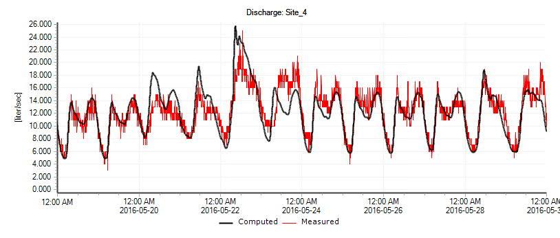

The model network could not be updated to include wastewater sewers and manholes constructed since 2018, as the City’s GIS datasets were incomplete. The datasets primarily contained the horizontal alignment (i.e., missing invert elevations) of recent infrastructure; in some instances, manholes were missing. Developments since 2018 were incorporated into the wastewater model by routing their discharges to the nearest manhole in the model network. However, a limitation of this approach is that the performance of the newer wastewater sewers (constructed after 2018) could not be evaluated. The model incorporates developments underway, such as the initial stages of Elan and Le Reve (Figure 4).
The imported catchments included population equivalents and areas, matching values implemented for determining water demands in the water distribution system model. Baseflow, dry weather flow and wet weather flow parameters for these catchments were assigned based on the flow gauge sewersheds from ISL Engineering and Land Services Ltd. (2018). For example, the parcels added to the model in the Triomphe Estates and Lakeview neighbourhoods are within the Site 4 sewershed and had the corresponding dry and wet weather flow generation factors assigned.
Once the model was updated, the City’s existing wastewater system was analyzed under typical conditions, namely dry and wet weather flow conditions (5- and 25-year, 24-hour design rainfall events). The system was assessed based on pipe surcharging ratios and maximum hydraulic grade elevations relative to the ground. These are explained in more detail next.
Wastewater sewer services are typically specified at a specific depth below the finished ground. In Beaumont, the City requires that wastewater services include at least 2.75 metres of cover. A hydraulic grade elevation higher than this minimum depth requirement means there is a risk of wastewater backing up to basements. Table 4.12 summarizes the criteria adopted in this study to identify the risk of flooding private property due to surcharging in the City’s system. The table also outlines the colour coding adopted to display model results in the assessment figures.

Greater than 0 meters Red dot Surcharging to the surface
Between -2.6 meters and 0 meters Orange dot Hydraulic grade above typical sanitary service
Between -3.5 meters and -2.6 meters Yellow dot Hydraulic grade below typical sanitary service
Less than 3.5 meters Green dot Hydraulic grade elevation 3.5 meters below the ground
Wastewater sewers are designed to flow less than full to maintain open channel flow conditions and provide space above the flow depth for ventilation. In Beaumont, the City specifies that its wastewater sewers are designed to flow up to 86 percent full at most. As such, the City’s system was also assessed based on the ratio of peak discharge relative to pipe capacity (full flow) as calculated using Manning’s equation. Table 4.13 summarizes the criteria adopted in this study to identify undersized sewers which may increase the risk of flooding private property. The table also outlines the colour coding adopted to display model results in the assessment figures.
Greater than 1.2 Red line Overcapacity – pipe surcharges
Between 1.0 and 1.2 Orange line Pipe flowing full to slightly over full capacity
Between 0.86 and 1.0 Yellow line Pipe flowing above desirable maximum ratio, but not full
Less than 0.86 Green line Pipe flowing within desirable maximum ratio, spare capacity
Pipes with ratios less than one indicate that the pipe is flowing less than full. Contrarily, ratios above one indicate that the pipe is surcharging and should be considered for upsizing.
Appropriate hydraulic assessment of the City’s system requires evaluating the hydraulic grade elevation relative to the ground in conjunction with the peak discharge relative to pipe capacity. The reason is that a hydraulic grade elevation below 2.6 metres relative to the ground is not a critical issue if no wastewater services are in the area. Furthermore, such hydraulic conditions may be inevitable if the wastewater sewer is shallower than is specified in more current design criteria. Similarly, while a surcharging pipe is not ideal as it changes flow hydraulics, it may not be of immediate concern if the hydraulic grade is below the typical wastewater services.
The model results for the existing system under dry weather conditions are shown in Figure 56. The City’s system can convey peak dry weather flows without issues. There are various manholes in the system with a simulated hydraulic grade above 2.6 metres relative to the ground. These are shallow sewers with the flow within the pipe diameter, as evidenced by a capacity utilization of less than one. Shallow sewers are present sparsely in Beaumont, although there is a noticeable cluster in the St. Vital neighbourhood (45 Street and 52 Avenue area) and Centre-Ville area (50 Street, south of 50 Avenue). All wastewater sewers in the City’s system flow less than 86 percent full, indicating sufficient capacity to convey dry weather flows. The model results showed a few sections (less than 10) of the 525-millimetre SERTS South surcharging or flowing over 86 percent full, just west of RR 243.
The model results for the existing system under rainfall-influenced conditions (5-year, 24-hour Huff rainfall event) are shown in Figure 57. There are a few additional manholes in the system, primarily along the SERTS South, with a simulated hydraulic grade above 2.6 metres relative to the ground.
Surcharging also occurs along Trunk Sewer 4 and a local sewer south of 40/42 Avenue. Table 4.14 summarizes issues under this scenario.
SEWER ID LOCATION ISSUE DISCUSSION
SERTS South Between the Beaumont Pump Station and the storage pipes south of 41 Avenue.
Trunk Sewer 4 Along 57 Street, between 55 Avenue and the SERTS South.
Surcharging throughout the described location of the trunk sewer.
Surcharging throughout the described location of the trunk sewer.
The existing SERTS South is overcapacity.
The existing sewer is overcapacity; however, the hydraulic grade throughout 57 Street remains mainly below 2.6 meters relative to the ground.
Local Sewer South of 40/42 Avenue South of 40/42 Avenue between 45 Street and the SERTS South.
Surcharging throughout the described location of the trunk sewer.
The existing sewer is overcapacity; however, the hydraulic grade remains below 2.6 meters relative to the ground.
The model results for the existing system under rainfall-influenced conditions (25-year, 24-hour Huff rainfall event) are shown in Figure 58. Appendix J includes several plans and profiles illustrating the simulated hydraulic grade under existing conditions. There are many additional manholes in the system, primarily along the SERTS South, Trunk Sewer 4 and a local sewer south of 40/42 Avenue, with a simulated hydraulic grade above 2.6 metres relative to the ground. The Dansereau Meadows neighbourhood is significantly affected by surcharging in the SERTS South, leading to hydraulic grades above typical basement service depths. Table 4.15 summarizes issues under this scenario.
SERTS South Between Beaumont Pump Station and the storage pipes south of 41 Avenue.
Surcharging throughout the described location of the trunk sewer.
The existing SERTS South is overcapacity, with a hydraulic grade above ground level near the Goudreau Terrace/Ruisseau SWMFs and west of RR 243. Surcharging affects Dansereau Meadows (Trunk Sewer 1) and other adjacent areas.
Trunk Sewer 4 Along 57 Street, between 55 Avenue and the SERTS South.
Surcharging throughout the described location of the trunk sewer, now extending beyond the trunk sewer to some laterals (48 Avenue, 43 Avenue).
The existing sewer is overcapacity, with a hydraulic grade above ground level near 55 Street and 48 Avenue. The hydraulic grade throughout 57 Street remains mostly below 2.6 meters relative to the ground.
Local Sewer South of 40/42 Avenue South of 40/42 Avenue between 45 Street and the SERTS South.
Surcharging throughout the described location of the trunk sewer, now extending up to Ecole Beau Meadow School.
The existing sewer is overcapacity; however, the hydraulic grade remains mostly below 2.6 meters relative to the ground. No services appear to be connected to this sewer.
Local Sewer on 50 Avenue 50 Ave between 55 Street and 50 Street.
Surcharging throughout the described location of the sewer.
The existing sewer is overcapacity, with a hydraulic grade near ground level.
Conceptual improvements were developed to address noted issues under the 25-year, 24-hour Huff rainfall event. The possibilities for system improvements comprise wet weather flow reduction, increasing conveyance capacity or providing interconnections or storage. Wet weather flow reduction includes, in practice, mitigating inflow and infiltration.
As discussed previously, the City’s wastewater system has areas with weeping tile connections. The City should confirm the location of weeping tile connections and consider disconnections, where possible. Weeping tile can be disconnected and redirected to a sump pump that discharges to the ground outside homes where water flows overland away from the foundation. Lots may need to be regraded to ensure drainage is moved away from the home. The City may explore providing subsidies for homeowners to undertake weeping tile disconnections or implementing outreach programs that encourage homeowners to undertake this work.
Other inflow and infiltration mitigation work includes the following:
· Sealing manholes, including covers;
· Replacing or rehabilitating leaky sewers (cured-in-place piping, slip lining, point repairs, etc.); and,
· Replacing or rehabilitating leaky services.
Inflow and infiltration sources can be detected by conducting manhole and sewer inspections, smoke testing or dye testing. Installing flow gauges in the City’s system also allows for identifying problematic sewersheds. The City has completed at least two inflow and infiltration assessment studies that assessed flow gauge data (WSP, 2022; ISL Engineering and Land Services Ltd., 2020). These studies identify problematic sewersheds suitable for mitigation. The extent of some proposed improvements may be lessened if the City undertakes inflow and infiltration mitigation work (or required at all). The need for the following proposed improvements should be evaluated after mitigation measures have been implemented and flow data is available demonstrating success in mitigation efforts.
Existing system improvements were developed, assuming no reduction of inflow and infiltration. The improvements aimed at reducing the risk of basement flooding first (hydraulic grade is at least 2.6 metres below ground), where possible. The pipe capacity utilization was also considered but not addressed unless it caused a high enough hydraulic grade that increased the risk of basement flooding.
Table 4.16 summarizes the system improvements proposed to address issues under the 25-year, 24hour Huff rainfall event. The concepts should be refined in subsequent stages of design. Improvements were categorized based on ownership with the assumption that the ACRWC would complete the SERTS South twinning. Figure 59 shows the location and extent of the proposed improvements.
UPGRADE ID LOCATION PROPOSED WORK ACRWC
ACRWC-WW-UPG-1
ACRWC-WW-UPG-2
Decommission the Beaumont Pump Station and complete twinning of the 900-millimetre sewer up to the SERTS South near Irvine Creek (about 3,100 metres of 900-millimetre pipe).
Complete twining upstream of the 1,200-millimetre SERTS South up to about the SERTS Storage Sewer (about 1,010 metres of 600/675-millimetre pipe).
WW-UPG-0
WW-UPG-1
WW-UPG-2
WW-UPG-3
Problematic sewersheds identified in previous inflow and infiltration assessment studies.
Trunk Sewer 4 along 57 Street between 55 Avenue and the SERTS South.
Local sewer south of 40/42 Avenue between 45 Street and the SERTS South.
Local sewer along 50 Ave between 55 Street and 50 Street.
Inflow and mitigation measures include weeping tile disconnection, sealing infrastructure and rehabilitating or replacing leaky sewers, services and manholes.
Upsize existing sewer with pipe diameters between 250 and 600 millimetres (about 1,405 metres)
Upsize existing sewer with pipe diameters between 300 and 375 millimetres (about 1,020 metres).
Upsize existing sewer with 250-millimetre diameter pipe (about 210 metres).
Figure 60 illustrates model results under the 25-year, 24-hour Huff rainfall event after implementing the proposed improvements. Appendix J includes several plans and profiles illustrating the simulated hydraulic grade with upgrades. Model results indicate that there continue to be manholes with a hydraulic grade line above 2.6 metres relative to the ground. These are primarily located in the St. Vital neighbourhood and Centre-Ville area (some are shallow sewers, as discussed previously). A subsidy for installing backflow prevention valves in homes could be considered for areas with shallow sewers. Inflow and infiltration mitigation work as part of neighbourhood renewal in these areas would further lower the risk of basement flooding and aid in reducing the hydraulic grade line in the area. A few select pipes, mainly in the St. Vital neighbourhood and Centre-Ville area, continue to have a capacity utilization ratio greater than 86 percent. However, these are deeper sewers, so the hydraulic grade is below 2.6 metres relative to the ground.
Completing the SERTS South twinning is critical to resolving surcharging issues throughout the City’s system; the effectiveness of proposed improvements within Beaumont would be limited. Table 4.17 prioritizes the wastewater system improvements to be completed by the City, including the rationale for priority assignment.
1 WW-UPG-0 Implementing inflow and infiltration mitigation measures may reduce the footprint of other City wastewater system upgrades or eliminate them (to be further assessed).
2 WW-UPG-1 Mitigates potential basement flooding at various properties along 57 Street adjacent to 55 Avenue/56 Street and 48 Avenue near 56 Street.
3 WW-UPG-3 Mitigates potential basement flooding at properties along 50 Avenue between 50 Street and about 54 Street.
4 WW-UPG-2 Improves the system hydraulics and does not mitigate basement flooding. The City’s GIS datasets indicate no services connected to this sewer west of 42 Avenue.
Inflow and infiltration mitigation is proposed as the highest priority project due to affecting the need for the other recommended improvements. Two proposed improvements to the City’s system mitigate basement flooding. The lowest priority improvement (WW-UPG-2) only improves conveyance in the system but does not mitigate basement flooding as no services are connected to the sewer west of 42 Avenue. The City should implement the improvements WW-UPG-1 and WW-UPG-3 in the short term. WW-UPG-3 could be coordinated with the upcoming 50 Avenue streetscaping work in 2024.
The ultimate servicing concept is shown in Figure 61. The concept was developed assuming all improvements proposed to the City’s and ACRWC's systems have been implemented (Table 4.16). The ultimate servicing concept comprises a series of trunk sewers and other infrastructure, such as lift stations and force mains in the growth areas. According to the Elan ASP, a lift station is required north of the SERTS South. Another lift station was required to service the Southlands ASP, which is expected to develop over the next five years. The Le Reve Lift Station and force main have been designed already and are expected to begin construction in 2024.
The vertical and horizontal alignment and pipe diameters of the trunk sewers within the Le Reve and Elan ASPs were based on data from the existing servicing reports. Detailed servicing is not shown for areas adjacent to existing developments, such as Triomphe Estates, Lakeview, Beau Val, Ruisseau, Dansereau Meadows and the south end of Colonial Estates. These areas will be serviced via the nearest local sewers that connect to the existing system.
The inter-municipal plan shows the lands north of Irvine Creek and the drainage course in Le Reve being serviced via a future trunk sewer in Edmonton (McElhanney Ltd., 2019). This future trunk was identified as a cost-shared infrastructure between the City of Beaumont and the City of Edmonton. Appendix A contains servicing concepts proposed in the inter-municipal plan. The plan also shows three future lift stations in the City’s system: one in the Le Reve ASP area, another in the Northwest Annexation Lands (south of Irvine Creek) and the final one in the lands south of HWY 625. The ultimate servicing concept proposed in this study deviates from the inter-municipal plan in that a portion of the Northwest Annexation Lands (north of Irvine Creek) would be serviced via the SERTS South instead of EPCOR’s SESS.
The following provides a brief rationale for the layout of the ultimate servicing concept:
· Southlands ASP: includes some low-lying lands, as this is where the LeBlanc Canal originates. These lands are expected to develop over the next four years, with much of the surrounding future development not envisioned to come online until after 2028. The optimal servicing point for the Southlands ASP is via the Beau Val neighbourhood and, ultimately, existing sewers in the Beaumont Lakes neighbourhood. A lift station is required because of ground elevation differences between Beau Val and the Southlands ASP. Servicing of these lands was also explored via the future HWY 625 trunk sewer and, eventually, the Elan ASP trunk sewer. However, this alternative was not carried forward primarily because of the timing of development in the Southwest Annexation Lands (after 2043).
· Southwest Annexation Lands: lands generally have higher ground elevations than the surrounding areas (except the wetland at HWY 625 and RR 243). These lands are proposed to be serviced via a future trunk sewer along HWY 625 and, ultimately, a future trunk sewer in the Elan ASP. Some upsizing of the Elan ASP trunk sewer may be required. Upcoming neighbourhood design report amendments in Elan should consider the flow contributions from these lands.
· Elan ASP: the concept for Elan follows the servicing scheme proposed in the Elan ASP and neighbourhood design reports. Key changes include an increase in servicing area, namely a portion of the Southlands ASP (west of 50 Street) and the lands north of TR 510 and west of 50 Street. The northwest lands can be serviced via one of the north trunk sewers in Elan without additional deepening. The pumping capacity requirements at the Elan Lift Station would be greater due to the increased service area.
· Northwest Annexation Lands: includes the lowest-lying lands within the City’s municipal boundary and generally slope towards Cawes Lake in the northwest. Wastewater servicing in this area was originally envisioned via the EPCOR SESS (McElhanney Ltd., 2019). The proposed servicing concept of these lands is via one of the north Elan ASP trunk sewers and the lift station.
· Le Reve ASP: the concept for Le Reve follows the servicing scheme proposed in the Le Reve ASP and neighbourhood design reports. The ASP shows lands south of Irvine Creek serviced by trunk sewers conveying wastewater to the Le Reve Lift Station and force main. The original intent is for the force main to discharge at the existing 300-millimetre sewer on TR 510 in the interim and, ultimately, a
future trunk sewer along the north end of TR 510 through the Dansereau Meadows neighbourhood. The EPCOR SESS will service the lands north of Irvine Creek in the Le Reve ASP (McElhanney Ltd., 2019).
Another workshop was held on 22 June 2023 to review the performance of the existing systems and present the proposed servicing concepts for the ultimate servicing concept. Appendix H includes a copy of the presentation and meeting minutes from the workshop. The ultimate wastewater system concept was revised subsequently and is not reflected in the Master Plan Workshop information.
Model detail for the growth areas was also coarse and focused primarily on the trunk sewers (greater than or equal to 375 millimetres) and lift stations. As stated, the model was configured assuming all improvements proposed to the City’s and ACRWC's systems have been implemented. For this study, the ultimate servicing concept model added sewers throughout future development areas, ultimately connecting to the existing network. Sewers were generally located along the arterial road network, if future development plans were available, or along assumed alignments based on the layout of adjacent future infrastructure. Smaller pipe diameter sewers were included occasionally to ensure the invert elevations were reasonable. The ultimate system was only assessed under the 25-year, 24-hour Huff rainfall event, which is the governing event.
Sewersheds were created for all growth areas based on existing statutory plans (if available) or the municipal development plan. Population values were estimated based on land uses and the projected population. Wastewater generation rates for residential and non-residential were determined using the City’s General Design Standards. Figure 62 illustrates the ultimate wastewater system, including catchment routing. The ultimate system model was based on the following assumptions:
01 All existing system improvements (Table 4.16) to the City’s and ACRWC's systems have been implemented;
02 All future connections to the SERTS South in the Elan ASP would be to the 900-millimetre trunk sewer. The existing 525-millimetre trunk sewer is overcapacity;
03 Areas designated as utility right of way, municipal or environmental reserves, or public utility lots for SWMFs do not contribute any flows (dry or wet);
04 Future municipal roadways contribute wet weather flows;
05 Inflow and infiltration rates in older areas of Beaumont remain constant; and
06 Future sewersheds contribute up to 0.28 L/s/ha of wet weather flows to the wastewater system under the 25-year, 24-hour design rainfall.
07 All future lift stations were included in the model strictly for lifting flows. No force main was included at the discharge end of the lift stations in the model.
The peaking factor formula in the City’s General Design Standards was challenging to implement as it decreases inversely with population. Instead, a constant residential peaking factor was implemented in the model for the future residential sewersheds. The peaking factor was derived from reviewing flow gauge data collected in 2022 by the ACRWC and the City. Figure 63 shows the weekday and weekend wastewater diurnal patterns for Beaumont.
The highest peaking factor in Beaumont is about 1.8 on average for weekends. The model implemented a peaking factor of 2.0, so the residential wastewater flows were slightly conservatively estimated.


The model results for the ultimate system under rainfall-influenced conditions (25-year, 24-hour Huff rainfall event) are shown in Figure 64. There are various manholes in the system, primarily along the SERTS South and Dansereau Meadows with a simulated hydraulic grade above 2.6 metres relative to the ground. Surcharging along the SERTS South also affects other surrounding neighbourhoods south of Rue Eaglemont. This leads to hydraulic grades between 3.5 and 2.6 metres relative to the ground and the future trunk sewer connections in the Elan ASP. Other sewers that experience surcharging include Trunk Sewer 1 and Trunk Sewer 7; however, the hydraulic grade along these sewers is mostly below 2.6 metres relative to the ground. Table 4.18 summarizes issues under this scenario.
SEWER ID LOCATION ISSUE DISCUSSION
SERTS South West of the future Elan Trunk Sewer connection and the SERTS South near Irvine Creek.
Surcharging throughout the described location of the trunk sewer.
The SERTS South is overcapacity, with a hydraulic grade near ground north/west of 44 Avenue. Surcharging affects Dansereau Meadows (Trunk Sewer 1) and other adjacent areas.
Improvements were developed to accommodate growth from the ultimate development horizon, assuming no reduction of inflow and infiltration. The improvements aimed at reducing the risk of basement flooding first (hydraulic grade line is at least 2.6 metres below ground), where possible. The pipe capacity utilization was also considered but not addressed unless it caused a high enough hydraulic grade that increased the risk of basement flooding.
Table 4.16 summarizes the only system improvement proposed to address issues under the 25-year, 24hour Huff rainfall event in the ultimate development horizon. The concept should be refined in subsequent stages of design. Improvements were not developed for Trunk Sewer 1 or Trunk Sewer 7 as these sewers generally experienced slight surcharging, and the hydraulic grade was mostly below 2.6 metres relative to the ground. Figure 65 shows the location and extent of the proposed improvement.
ACRWC-WW-ULT-UPG-1 Between the future Elan ASP trunk sewer and the SERTS South near Irvine Creek.
Upsize the 900-millimetre sewer from the Elan Lift Station connection to the SERTS South near Irvine Creek (about 4,200 metres of 1,200-millimetre pipe).
Figure 66 illustrates model results under the 25-year, 24-hour Huff rainfall event after implementing the proposed improvement. Appendix J includes several plans and profiles illustrating the simulated hydraulic grade at key sewers under the ultimate development horizon with and without upgrades. Model results indicate a stretch of trunk sewer on the SERTS South, south of 50 Avenue that experiences significant surcharging due to increased wastewater flow contributions. However, the surcharging does not negatively impact the City’s system and ensures the SERTS South 2 Storage (2 x 2,100-millimetre pipes) is fully utilized. Increasing conveyance downstream of the storage pipes would address surcharging but lead to a reduction in storage utilization.
Figure 67 shows the ultimate wastewater servicing concept according to each development stage. Figure 68 to Figure 90 illustrate the infrastructure needs and staged servicing concepts for each development horizon. Infrastructure needs are also summarized in Table 4.20 according to development horizon and system owner (the City or ACRWC) or as required to service future developments.
2023-2027 Buildout City of Beaumont
ACRWC
Development Servicing
· WW-UPG-0: Inflow and infiltration mitigation program (yearly during this development horizon). Implementation based on problematic areas identified in previous inflow and infiltration assessment studies.
· ACRWC-WW-UPG-1: Completing twinning of the SERTS South (900 mm sewer) from the Beaumont Pump Station (west of RR 244) up to the existing SERTS South near Irvine Creek. Decommissioning of the Beaumont Pump Station.
· ACRWC-WW-UPG-2: Completing twinning of the SERTS South (600/675 mm sewer) up to about the SERTS South Storage Sewer.
· Trunk sewers in the Elan ASP, Le Reve ASP (including the Le Reve Lift Station and force main), and the Southlands ASP (including the Southlands Lift Station). Le Reve Lift Station ultimate design flow is about 197 L/s, while it is 110 L/s for the Southlands Lift Station. Sewer sizes range between 300 mm and 600 mm—additional local sewers throughout these areas.
o The trunk sewer through Dansereau Meadows required for Le Reve may be delayed pending further analysis.
2028-2032 Buildout City of Beaumont
· Depending on the success of WW-UPG-0: Inflow and infiltration mitigation program, the need for and footprint of the following upgrades should be reviewed:
o WW-UPG-1: Upsize Trunk Sewer 4 along 57 Street between 55 Avenue and the SERTS South with 250-600 mm sewers.
o WW-UPG-2: Upsize local sewer south of 40/42 Avenue between 45 Street and the SERTS South with 300/375 mm sewers.
o WW-UPG-3: Upsize the local sewer along 50 Avenue between 55 Street and 50 Street with 250 mm sewer.
Development Servicing
2033-2037 Buildout Development Servicing
2038-2042 Buildout City of Beaumont
Development Servicing
· Trunk sewer in the Le Reve ASP. Sewer size is 375 mm–additional local sewers throughout this area, the Elan ASP, Beau Val, Lakeview and Coloniale Estates.
· Trunk sewers in the Elan ASP and the Southlands ASP. Sewer sizes range between 300 mm and 450 mm—additional local sewers throughout these areas.
· Trunk sewer along 50 Street to SESS for servicing the north sewershed of the Le Reve ASP.
· Trunk sewers in the Elan ASP and the north sewershed in the Le Reve ASP. Sewer sizes range between 375 mm and 525 mm— additional local sewers throughout these areas, the Southlands ASP, Lakeview, and the Northwest Annexation Lands.
2043-2047 Buildout Development Servicing
2048+ Buildout ACRWC
Development Servicing
· Trunk sewers in the Le Reve ASP and the Elan ASP and the Southwest Annexation Lands. Sewer sizes range between 375 mm and 525 mm—additional local sewers throughout these areas.
· ACRWC-WW-ULT-UPG-1: Upsizing the 900 mm trunk sewer on the SERTS South (1,200 mm sewer) from the Elan Lift Station connection to the existing SERTS South near Irvine Creek.
· Trunk sewers in Elan ASP (including the Elan Lift Station), Southwest Annexation Lands, Northwest Annexation Lands and the Le Reve ASP. Elan Lift Station ultimate design flow is 325 L/s. Sewer sizes range between 300 mm and 675 mm—additional local sewers throughout these areas.
The City’s stormwater system includes a network of underground sewers (minor system) and overland conveyance channels such as roads, ditches, culverts and storage facilities (major system). Catch basins, inlets in the minor system, and overland conveyance channels collect and convey stormwater to a series of wet and dry ponds interspersed within Beaumont. These ponds, known as stormwater management facilities (SWMFs), provide peak flow attenuation of urban runoff and water quality improvements prior to discharge. The LeBlanc Canal is the primary outlet for the City’s stormwater system and has been upgraded several times since its construction in the 1920s. LeBlanc Canal discharges into Irvine Creek at the northwest limits of the City. Surface watercourses include Clearwater Creek to the south, Blackmud Creek to the west, and Irvine Creek to the north. The City’s existing stormwater system is shown in Figure 74.
The previous stormwater management plan was focused on evaluating existing SWMFs, at that time and the impact of the LeBlanc Canal and future SWMFs on the stormwater system. This study did not evaluate conveyance infrastructure (sewers, roadways, or ditches). Relevant findings from this report and the latest Beaumont Stormwater Management reports included:
· Older SWMFs could not contain the 100-year, 24-hour design storm runoff volumes (Coloniale, Triomphe Estates, Caradon, Brookside, Four Seasons Estates, Montrose Estates and business centre and Cairns);
· Newer SWMFs were designed to release at 1.8 L/s/ha and were appropriately sized to contain runoff from the 100-year, 24-hour design storm;
· Some newer SWMF facilities along the LeBlanc Canal have removed channel/floodplain storage. Restoration of this storage was recommended; and
· Preliminary estimates for older SWMF upgrades were provided, along with future developments and 50 Street upcoming upgrades that had been identified at the time of the report.
The Blackmud/Whitemud Creek Surface Water Management Study (BWCSWMS) by Associated Engineering, 2017, was consulted, as Beaumont lies within the Blackmud Creek watershed. The BWCSWMS recommended a stormwater management strategy for future developments and aimed to develop consistent design criteria, establish a maximum unit area release rate (UARR), and provide general recommendations for future water management. More specifically, the Study recommended the following:
· Adopting a 3.0 L/s/ha maximum UARR for the 100-year event, recognizing that this value differs from pre-development UARR in Irvine Creek and the LeBlanc Canal;
· Rather than sterilizing areas that regularly flood for development, use these to locate SWMFs or wetlands;
· Two concepts (channel improvements and trunk sewers) were identified to mitigate the impacts of increased flows from future developments. The concept consisted of using the existing channel to convey runoff from undeveloped lands and using the storm trunk sewer to convey discharges from SWMFs in developments. Channel improvements were recommended along Irvine Creek and the LeBlanc Canal. Irvine Creek is recommended to have an improved cross-section along the majority fo the north portion of the Creek, while LeBlanc Canal is recommended to be upgraded downstream of RR 243.
· Implement wet ponds or wetlands in the watershed (except the EIA due to bird strike hazards) and promote LID features.
Upon completion of the BWCSWMS, the City and other municipalities and EPCOR stated that all parties agreed to a maximum UARR of 3.0 L/s/ha for all new developments effective 1 January 2018, but parties can adopt lower UARR values where applicable. The letter also stated that existing developments that discharge at different rates will continue to do so.
A review of previous reports indicates that the appropriate UARR for facilities along the LeBlanc Canal may vary from the 3.0 L/s/ha rate:
· The LeBlanc Canal Intermunicipal Drainage Study by GPEC, 2001 states that “A controlled discharge rate of 1.8 l/s/ha was used in this study … this rate closely approximates the 1:5 year peak predevelopment runoff rate.”.
· The 2009 Beaumont Stormwater Management Plan (Revised in 2016) applied the recommended rate of 1.8 L/s/ha as per the GPEC, 2001 report.
· The Elan ASP states, "The proposed discharge rate from each facility is set to match pre-development storm runoff rates, to a maximum of 1.4 L/s/ha” based on “a preliminary engineering study on Irvine Creek, including the LeBlanc Canal” completed by Sameng in 1991.
Facilities within Beaumont largely drain to the LeBlanc Canal and flow into Irvine Creek, and from the supporting documentation, the pre-development UARR for these facilities may be between 1.4 and 1.8 L/s/ha instead of the overall watershed value of 3.0 L/s/ha.
WSP reviewed the current stormwater system GIS data provided by the City. The minor and major system elements were compared against drawings to perform quality checks for pipe lengths, elevations, manholes, and manholes. Similar quality checks were completed for major conveyance and storage facility capacity, outlets, ditches, and culverts. This section summarizes the findings from the GIS review.
The minor system refers to the network of underground storm sewers, catch basins, and inlets which convey storm runoff away from road surfaces. The City’s storm system includes approximately 75 km of storm sewer, ranging from 150 mm to 1800 mm in diameter. The storm sewers consist mainly of PVC pipe, with some concrete and HDPE pipes and one corrugated metal pipe (CMP). Most of the City’s storm sewers were constructed after 2000, with some constructed as early as 1976. Figure 74 through Figure 76 illustrate the pipe size, material, and installation period of the storm sewers. The lengths and composition of the storm pipes by size, material, and installation period are summarized in Table 5.1 through Table 5.3 below.
Notes:
01 GIS data was reviewed and refined, this included identifying unusual pipe diameters and making appropriate assumptions where possible.
Notes:
01 GIS data was reviewed and refined, this included making appropriate assumptions when pipe material was not clear.
The major system consists of overland conveyance channels such as roads, ditches, storage facilities, LeBlanc Canal, and Irvine Creek. Ditches collect and convey stormwater and are expected to provide some stormwater storage upstream of culverts which may help attenuate peak flows. The City has 39 SWMFs, consisting of 37 wet ponds and two dry ponds, and one underground storage tank located in Centre-Ville. The SWMFs provide peak flow attenuation of urban runoff and water quality improvements prior to releasing discharges to the LeBlanc Canal and ultimately to Irvine Creek in the northwest. Information regarding SWMF type, installation year, and available active storage is summarized and presented in Table 5.4 below. The available active storage indicates the maximum SWMF capacity without overtopping and potentially causing property damage. This is based on the maximum volume of the SWMF, potentially incorporating freeboard information where available. Table 5.4 also includes two additional partially constructed ponds, Lakeview and Ruisseau South. These SWMFs are assumed to be partially constructed in the existing system assessment. LeBlanc Canal is the major system feature within Beaumont and receives drainage from most SWMFs.
The City’s stormwater system includes approximately 213 culverts ranging from 100 mm to 3000 mm in diameter. The storm system primarily includes metal culverts, with some concrete and PVC culverts as well. The composition of the culverts by size and material are summarized in Table 5.5 through Table 5.6 below.
Catchments were delineated based on the existing topography and drainage patterns. The catchment areas were delineated using the digital elevation model (DEM) and aerial imagery provided by the City. Catchments properties were estimated by aerial inspection and applicable land use maps and had typical design parameters applied accordingly.
The catchments within the model are connected to the stormwater system, with the major stormwater basins largely delineated by the SWMFs. Occasionally, catchments are conveyed directly to outlets instead of a SWMF. All model catchments were tagged based on land use type. Catchments and their land use types are shown in Figure 77. As outlined in Table 1.1, the City land use largely consists of agricultural, residential, commercial, and light industrial. Most of the developed town is residential, with agricultural lands surrounding it.
The City identified three catchment areas outside of the main development core to the north, south, and southwest that are not a part of the main stormwater system but are important for assessment. These areas are as follows:
· The area to the north consists of agricultural lands which do not drain through the developed portion of the City.
· The area to the southwest consists mainly of agricultural lands, with two RV parks within the area. Most of this area drains to the north without entering the City, except for approximately 6 ha of area, which drains to the City via a culvert across Range Rd 243.
· The area in the south consists of approximately 435 ha of agricultural land, which drains into the City via a culvert across HWY 625.
Additional offsite areas include approximately 305 ha of agricultural lands to the east, which enter the City limits via two different culverts across Range Rd 241.
A performance review workshop was held on 1 December 2022 to review the performance of the existing stormwater system—the workshop aimed to understand the overall function of the City’s system and known issues. Appendix D provides a marked-up figure of the City’s stormwater system, documenting the key items identified during the performance review workshop.
Generally, no major observed issues are within the developed portion of Beaumont. City staff identified that some SWMFs have flooded in the past and SWMFs and sections of storm sewer sections have odour issues. Additionally, some issues were noted in the undeveloped areas within the City limits, primarily at the north and west boundaries of the City.
The City of Beaumont General Design Standards (City of Beaumont, 2021) were consulted during the stormwater system model build and existing system analysis. The applicable design criteria for major and minor systems are summarized below:
· The minor system elements shall be designed to collect and convey runoff generated by a 1 in 5-year storm event without surcharge.
· The major system shall have conveyance elements designed to accommodate runoff rates and volumes for a 100-year return period rainfall event. Peak flows and ponding in developed areas shall be limited such that there is no significant hazard to the public and the risk of erosion and property damage is limited. Depths of flows and ponding in roadways and public utility lots shall be a maximum of 0.3m.
The stormwater model was developed in PCSWMM to assess the City’s stormwater infrastructure. PCSWMM is a GIS-based version of the United States Environmental Protection Agency Storm Water Management Model (US EPA SWMM or SWMM). SWMM is a dynamic rainfall-runoff computer program that stimulates single event or continuous rainfall time-series runoff quantity and quality. The program simulates runoff from the model sub-catchments and routes the runoff through the hydraulic network during the simulation period. As per the City’s standards, the SWMM models are preferred for the design of drainage systems.
The hydraulic network was modelled using a dual drainage approach to capture major and minor system performance. A dual drainage model combines surface flows routed overland (roads, ditches, culverts) with underground flows (storm sewers). The major and minor systems are linked at roadway catch basins which capture and route surface flows to the underground storm sewers.
The hydraulic model was developed using current stormwater system GIS data provided by the City. WSP reviewed the current stormwater system GIS data, and the minor-system elements were compared against drawings to perform quality checks for pipe lengths, elevations, and manholes. The model was constructed by importing sewers, manholes, culverts, and ditches into PCSWMM. The imported network
was reviewed; isolated pipes and manholes, and sewer connection risers were deleted. The following modifications were made to refine the imported assets further and to rectify data gaps:
· Manhole rims with no specified elevations were assigned rim elevations using LiDAR data;
· Missing sewer diameters were assumed based on upstream and downstream sewers;
· Missing storm sewer lengths were assigned using their GIS-scaled length; and
· Missing manhole and storm sewer inverts were interpolated from the upstream and downstream network.
Similar to the water and wastewater models, new developments not included in the City’s GIS dataset were represented in the model in a simplified way, with the flows from each area lumped at the end node in the area.
Catch basins and catch basin leads were not imported into the model but were considered when modelling the links between the major and minor systems. These links were modelled as outlets and assigned rating curves depending on the number of connected catch basins.
SWMFs were modelled as storage nodes. Wherever possible, depth-area storage curve data was assigned from record drawings or imported from the Revised 2016 Stormwater Management Report by Focus; this data was reviewed to ensure its accuracy. Where storage curve data was unavailable, the storage creator tool in PCSWMMM was used to create storage curves from terrain data. SWMFs were modelled at their maximum volume, incorporating freeboard information when available. This assesses the maximum SWMF capacity before overtopping and potentially causing property damage.
The Leblanc Canal was constructed and modelled as a part of the major system. Model data from the Revised 2016 Stormwater Management Report by Focus was imported to generate the LeBlanc Canal. WSP applied the previous model data of the canal alignment, length, and transects; this data was reviewed to ensure its accuracy.
Catchment hydrologic parameters were set based on and the City of Beaumont General Design Standards (City of Beaumont, 2021) and topographical data (area, width, slope, and flow length). Catchments are divided into pervious areas that allow for surface runoff infiltration and impervious areas that do not allow any infiltration and result in direct runoff. The percent impervious for each catchment was estimated based on typical values for each land use type and assessment of recent aerial imagery. Table 5.7 summarizes the percent impervious value adopted for each land use type. Impervious values for a few catchments were adjusted based on aerial imagery and deviated from the values in Table 5.7.
The Horton method was employed to model infiltration for the pervious areas in all model catchments. The Horton method is based on empirical observations showing that infiltration decreases exponentially from an initial maximum rate (initial rate) to some minimum rate (final rate) over the course of a long rainfall event. These rates are representative of soil characteristics such as hydraulic conductivity and saturation. This method also requires a decay factor which describes how fast the rate decreases over time. Table 5.8 summarizes hydrological modelling parameters from the City’s standards, including Horton's infiltration parameters and other catchment parameters such as depression storage values and Manning’s n coefficients.
Design rainfall depths applied from the City of Edmonton Design Standards Volume 3-2, February 2022, by EPCOR. These rainfall events are based on rain gauge data from 11 stations from 1914 – 2020. These values were applied instead of the City of Beaumont General Design Standards as the current rainfall data from the City of Edmonton has been revised, providing a more accurate representation of rainfall events within the area. Note that the design storms simulated in this analysis feature higher intensity values than those utilized in the storm sewer system design. The 5-year, 4-hour Chicago Distribution storm was simulated to assess the minor system, and the 100-year, 24-hour Huff Distribution was simulated to assess the major system as per the City’s standards. Two additional Huff Distributions design storms, 5year, 24-hour and 25-year, 24-hour, were also simulated to assess the major stormwater system over a shorter return period. Table 5.9 presents the rainfall depths and peak intensities for the simulated design storm events.
The ultimate growth model is an extension of the existing stormwater system model. The hydraulic model was updated using future land use mapping and planning documents to construct the ultimate growth scenario. This primarily consisted of new growth within the undeveloped areas of the City limits, with some redevelopment in Centre-Ville at the core of the City. Figure 6 includes the names and locations of all existing and future neighbourhoods considered for the ultimate growth scenario and identifies the Northwest Annexation lands and Southwest Annexation lands not covered under any ASPs or NSRs.
New growth areas in the model were represented in a simplified manner. The model only includes major infrastructure such as SWMFs, interconnecting trunk sewers, and pumps. All of the subcatchments were delineated to a major infrastructure level. Flows from each new growth area were routed to a SWMF, and only the interconnecting SWMF trunks were modelled.
Wherever possible, depth-area storage curve data was assigned from drawings or planning documents. Detailed SWMF storage information was available for the following areas: Elan, Le Reve, and Lakeview. The development concepts for Beau Val Park and the Innovation Southlands included layouts of the proposed SWMFs, but no additional information was available. Where storage curve data was unavailable, new SWMFs were initially estimated from the values summarized in Table 5.10. The actual calculated required storage values for the future facilities were based on model results and are presented in Section 5.8.1.
Notes:
01 Assuming a square base
The Northwest and Southwest Annexation lands had no available planning documents, so approximate locations for SWMFs were determined based on existing topography. The SWMFs were sized and modelled based on the assumptions presented in Table 5.10 above.
As with the existing model, future catchment hydrologic parameters were set based on the City of Beaumont General Design Standards (City of Beaumont, 2021) and topographical data. Land use for each area was determined based on the land use shapefiles provided by the City. Subcatchments were broken down into residential and commercial parcels, and the appropriate parameters were applied. Table 5.7 summarizes the percent impervious values adopted for each land use type. Table 5.8 summarizes hydrological modelling parameters from the City’s standards, including infiltration parameters, depression storage values, and Manning’s n coefficients. The 100-year, 24-hour Huff Distribution design storm was simulated to assess the major infrastructure for the ultimate growth scenario (Table 5.9).
Proposed redevelopment for the City is limited to downtown and mature neighbourhood areas at the core of the City as outlined in the Centre-Ville Area Redevelopment Plan (CARP) (2019). Underutilized land and larger parcels in Centre-Ville were identified as opportunities to develop a mixed-use downtown with residential infill.
The proposed land-use changes increase impervious areas and generate additional stormwater runoff. The percent impervious for each model catchment was adjusted to reflect the change in land use type. An imperviousness value of 80% was applied to all new mixed-use areas, while institutional and residential subcatchments were reviewed on a case-by-case basis and adjusted within the typical values for each land use type. Table 5.7 summarizes typical percent impervious values for each land use type.
The need for additional stormwater storage to offset the increase in stormwater runoff was identified in the Centre-Ville Infrastructure Servicing Study (2018). Six new underground storage tanks were proposed, including their approximate locations, required storage volumes, and proposed connections to the stormwater system. The new underground storage tanks were modelled as storage nodes and connected to the existing system. Connection points to the existing system were not identified for three underground tanks and were assumed based on proximity to existing stormwater infrastructure. The analysis and recommendations presented in the Centre-Ville Infrastructure Servicing Study (2018) were based on dividing the plan area into eight subcatchments and providing additional storage requirements on a per-catchment basis. However, in the current model, catchments in the core area were discretized into smaller catchments. As a result of the difference in discretization, the catchment areas serviced by each storage tank in the model are slightly less than those presented in the CARP.
The PCSWMM dual drainage model was used to simulate four different design storm events for the stormwater system to assess pipe capacities. Figure 78 through Figure 81 illustrate the performance of the minor system, including pipe capacity assessment results for the stormwater system under those conditions. The links with capacity ratios (Qmax/Qcap) greater than 1.0, the ratio of the maximum simulated flow over capacity flow rate, are highlighted in red. Pipes with capacity ratios between 0.86 and 1.00 are highlighted in yellow, while pipes with capacity ratios less than 0.86 are highlighted in green, with no concerns with capacity issues. Table 5.11 summarizes the results for each assessment scenario. As previously noted, the design storms simulated in this analysis feature higher intensity values than those utilized in the storm sewer system design. This increased intensity significantly contributes to the number of pipes nearing or exceeding capacity in the 5-year 4-Hour analysis.
DESIGN RAINFALL EVENT
5-year, 4-hour
5-year, 24-hour
25-year, 24-hour
100-year, 24-hour
Qmax/Qcap < 0.86: 863 pipes
Qmax/Qcap > 0.86: 98 pipes
Qmax/Qcap > 1.00: 405 pipes
Qmax/Qcap < 0.86: 1290 pipes
Qmax/Qcap > 0.86: 8 pipes
Qmax/Qcap > 1.00: 68 pipes
Qmax/Qcap < 0.86: 1208 pipes
Qmax/Qcap > 0.86: 39 pipes
Qmax/Qcap > 1.00: 119 pipes
Qmax/Qcap < 0.86: 1159 pipes
Qmax/Qcap > 0.86: 45 pipes
Qmax/Qcap > 1.00: 162 pipes
The maximum surface ponding depths and manhole depths were estimated for the stormwater network under the four simulated design storms. Figure 82 through Figure 85 illustrate the performance of the major system, including the surface ponding assessment results. The limits to differentiate different surface ponding zones were set at 0.0m, 0.15 m and 0.30 m. The system experienced shallow ponding depths (<0.15 m) at several locations throughout the stormwater network and a few areas with deep surface ponding depths (> 0.3 m). Table 5.12 summarizes the results for each assessment scenario. Areas of concern are reviewed in further detail in the following sections.
5-year, 4-hour
Minor System:
Depth is more than 1.0m below the rim: 995 manholes
Depth is less than 1.0m below the rim: 185 manholes
Flooding: 55 manholes
Major System:
Roadway surface ponding is less than 0.15m: 941 locations
Roadway surface ponding is between 0.15m and 0.30m: 76 locations
Roadway surface ponding is greater than 0.30m: 5 locations
5-year, 24-hour
Minor System:
Depth is more than 1.0m below the rim: 1209 manholes
Depth is less than 1.0m below the rim: 24 manholes
Flooding: 2 manholes
Major System:
Roadway surface ponding is less than 0.15m: 1014 locations
Roadway surface ponding is between 0.15m and 0.30m: 6 locations
Roadway surface ponding is greater than 0.30m: 2 locations
25-year, 24-hour
Minor System:
Manhole depth is more than 1.0m below the rim: 1107 manholes
Manhole depth is less than 1.0m below the rim: 121 manholes
Manhole is flooding: 7 manholes
Major System:
Roadway surface ponding is less than 0.15m: 1004 locations
Roadway surface ponding is between 0.15m and 0.30m: 16 locations
Roadway surface ponding is greater than 0.30m: 2 locations
100-year, 24-hour
Minor System:
Manhole depth is more than 1.0m below the rim: 1046 manholes
Manhole depth is less than 1.0m below the rim: 175 manholes
Manhole is flooding: 14 manholes
Major System:
Roadway surface ponding is less than 0.15m: 992 locations
Roadway surface ponding is between 0.15m and 0.30m: 28 locations
Roadway surface ponding is greater than 0.30m: 2 locations
The SWMFs were assessed using the 100-year, 24-hour Huff design storm. The PCSWMM stormwater model simulation results were used to estimate the release rates of each stormwater pond.
Table 5.13 summarizes the total contributing area, NWL, HWL, model release rate, and simulated HGL for each SWMF. Many of the ponds within the City are hydraulically connected. Thus, the drainage area for each pond is the total contributing area, including areas from other ponds.
Table 5.13 also includes two additional partially constructed ponds (Elan and Ruisseau South), as well as underground storage located in Centreville.
Model results indicated that most SWMFs provided adequate storage based on the 100-year, 24-hour Huff design storm. However, potential issues were identified for the following SWMFs:
· Brookside
· Caradon
· Coloniale Pond 3A
· Coloniale Pond 4
· Triomphe
· Eaglemont Heights
· Dansereau Meadows South
Flooding of SWMFs may result from too much control at the outlets or undersized ponds. Further discussion on potential issues and remediation for some of the listed SWMFs is provided in the following section.
SWMF,
The control orifice to LeBlanc Canal is designed to a maximum release rate of 1.8 L/s/ha, however during the 100-Year 24-Hour storm the HWL is exceeded and there is additional flow through the overflow culverts into the canal. This issue is discussed further in Section
During the 100-Year 24-Hour storm the freeboard elevation is exceeded, this issue is discussed further in Section 5.7.4.
Receives flow from offsite agricultural areas to the east of RR 241. During the 100-Year 24-Hour storm the freeboard elevation is exceeded. This is potentially due to over estimation of flows from agricultural areas in model. This is an interim SWMF which will be expanded in the future.
01 Includes area from upstream SWMFs
02 Based on the 100-Year 24-Hour storm 03 Freeboard elevations are estimated based upon topographic data where detailed information is not available
Areas of potential concern were identified based on reviewing the performance of the minor and major systems. These locations were identified to review the conditions, causes, and initiate discussion on potential remedial action, and are summarized in Table 5.14 and shown in Figure 86. WSP staff met with the City staff on April 28, 2023, to review the in-progress stormwater model and discuss the initially identified areas of concern. This workshop aimed to develop a better understanding of the stormwater system functionality and assist with the proposed system improvements outlined below. Appendix K includes meeting minutes from the Stormwater System Workshop.
1 Soleil Blvd (east of Rue Parc) Flooding, due to local low point/ road sag.
2 56 Ave & 53 St
Flooding at cul-de-sac that is located at a low point. Cul-de-sac drains to a single catchbasin and routes water to north commercial lot.
3 55 Ave & 49 St Potential minor flooding concerns at townhall parking lot, due to low point and limited catchbasin conveyance.
4 HWY 814 (north of TWP 510)
Flooding concerns near HWY 814 upstream of culvert
Improve road grading or catchbasin capacity Review road grading in person to validate low point and potential catchbasin improvements.
Increase catchbasin capacity a cul-de-sac. Improve road grading/ drainage at commercial site.
Grading at this commercial lot directs flow further north towards its parking lot, causing additional potential flooding concerns. Grading of the commercial lot should be reviewed and validated in person.
Increased catchbasin capacity, or potential major routing to green space. Potential LID location.
No known flooding from discussions with City. Green space provides opportunity for potential LID.
5 46 St & 45 St (south of 52 Ave) Potential flooding/ ponding concerns due to lack of minor system conveyance.
6 South of École Bellevue School
Flooding due to control structure downstream of the school.
No immediate resolutions determined. As the Le Reve/ North development area builds out the system infrastructure will reduce flooding concerns. Potential discussions with the Coloniale Golf Club and operation of their ponds may assist in reducing potential flooding concerns.
Improve road grading where possible. Implement LID infrastructure to reduce overall runoff. Potentially extend minor system into neighbourhood if LID cannot make an impactful reduction.
Ensure there is an overland drainage path, and site is inspected regularly (especially during spring melt).
The HWY 814, Irvine Creek, and north basin area is a complex issue under review with the City. On-site blockages of existing drainage paths are adding to concerns. On going discussions with the land owners, and means of reducing flow to the North basin are the primary supported resolution.
This area relies on major grading to relieve runoff, and is subject to potential ponding concerns due to the lack of minor system. The implementation of LID allows for runoff reduction without having to extend the minor system.
Orifice was discussed during workshop with City. It is known to cause icing issues, but is likely in place to prevent flooding in the downstream system. It is not recommended to be removed, as it may have a negative impact downstream. It is important though an overland drainage route is available. Signage of potential icing may be relevant.
7 CB near 42 St (between 46 Ave and 47 Ave)
Flooding at CB located in natural area due to large tree'd area draining to a single backyard catchbasin.
No recommend actions. Ensure local neighbour does not have any historical issues. Inspect CB and clean as necessary
Flooding within the tree stand is not a major concern unless there are known historical issues.
8 Reichert Dr (between Renaud Crt and Radisson Crt)
Potential flooding due to road sag. Increase catchbasin capacity. Road sags and has no overland routing. Confirm road grading in person.
9 Coloniale Golf and Country Club Local flooding on western portion of golf course. No recommend actions. Flooding concerns on private property of golf course.
10 Flooding of lands downstream of Coloniale Pond 2
Flooding downstream of pond towards agricultural lands in the north.
Known issue and being reviewed with the City. Resolutions include additional control at the pond outlet, pond upsizing, or adding a storage facility downstream of the culvert crossing TWP 510 to the north.
11 Coloniale Pond 3A Flooding of SWMF and of surrounding golf course. No recommend actions. Flooding concerns on private property of golf course.
Flooding within the golf course, limited risk to damage property. Golf course may re-grade or utilize french drains to reduce ponding.
Flooding in this area is a known concern and was discussed with the City during the Performance Review Workshop. Operation of Coloniale ponds should be further reviewed with Golf Club Owners. Future developments of Le Reve will assist in downstream flooding concerns as additional stormwater infrastructure is built. See Section 5.7.5 for further discussion.
Flooding within the golf course, limited risk to damage property. Golf course may expand pond, or re-grade to improve facility capacity. Large offsite area is routed to facility, upstream control would help reduce flooding.
12 Coloniale Pond 4 Flooding of SWMF and of surrounding golf course. No recommend actions. Flooding concerns on private property of golf course.
13 LeBlanc Canal 1 (HWY 625, east of HWY 814) Flooding in LeBlanc Canal at HWY 625 crossing to south agricultural lands.
No recommended action. Limited risk to property or person with flooding. Long term buildout will reduce concerns. Proposed flow monitoring at this location.
Flooding within the golf course, limited risk to damage property. Golf course may expand pond, or re-grade to improve facility capacity. Facility looks to be undersized for servicing catchment.
Culverts across HWY 625 are potentially causing localized backup. The culverts convey flows from large agricultural area to the south. No known issues of flooding, potential over estimation of flows in model; flow monitoring recommended. See Section 5.7.5 for further discussion.
14 LeBlanc Canal 2 (Caradon Pond) High water levels in Canal and around SWMF
No recommended action for improvements at this time. Ensure canal is cleaned and culverts are cleaned and clear.
High water levels in this portion of the canal may potentially result in overtopping of flows into the nearby SWMFs. Culverts constrict some flows but do not result in property damage. Recommended Canal maintenance, and general education of residents to stay away from facilities and canal during major storm events. See Section 5.7.5 for further discussion.
15 LeBlanc Canal 3 (Ruisseau and Goudreau Ponds)
High water levels around SWMFs. No recommended action for improvements at this time. Ensure canal is cleaned and culverts are cleaned and clear.
High water levels in this portion of the canal may potentially result in overtopping of flows into the nearby SWMFs. Culverts constrict some flows but do not result in property damage. Recommended Canal maintenance, and general education of residents to stay away from facilities and canal during major storm events. See Section 5.7.5 for further discussion.
16 LeBlanc Canal 4 (Eaglemont Pond) Flooding in Leblanc Canal near culverts. No recommended action for improvements at this time. Ensure canal is cleaned and culverts are cleaned and clear.
High water levels in this portion of the canal may potentially result in overtopping of flows into the nearby SWMFs. Culverts constrict some flows but do not result in property damage. Recommended Canal maintenance, and general education of residents to stay away from facilities and canal during major storm events. See Section 5.7.5 for further discussion.
17 LeBlanc Canal 5 (Eaglemont Heights and Dansereau Meadows South Ponds)
Flooding at SWMF. No recommended action for improvements at this time. Ensure canal is cleaned and culverts are cleaned and clear. Ensure immediate downstream of culverts is also clear. Proposed flow monitoring at this location.
High water levels in this portion of the canal may potentially result in overtopping of flows into the nearby SWMFs. Culverts constrict some flows but do not result in property damage. Recommended Canal maintenance, and general education of residents to stay away from facilities and canal during major storm events. Proposed flow monitoring at this location. See Section 5.7.5 for further discussion.
18 Triomphe Flooding at SWMF. Inspect outlet control at wetland, and review the wetland system to understand its behaviour.
The neighbouring wetland next to Triomphe is not modelled due to its unknown performance conditions, as such the additional storage provided by the wetland is not accounted for. Outlets from the wetland may also be undersized to control flows for the wetland, but no detailed informaiton of the wetland operational behaviour was available. It is expected the wetland would reduce flooding levels within Triomphe if accounted for. It is recommended an in person review of the outlet, and wetland complex be completed.
19 Southwest Annexation Lands (RV
Flooding at RV park in southeast corner. Ensure downstream channels are cleaned. Ensure upstream culverts across HWY 625 are cleaned and clear. Long term buildout will reduce concerns.
Flooding of the RV lands is a known concern and was discussed with the City during the Performance Review Workshop. Limited remedial actions are available as the property is built low and prone to flooding. Issues will be resolved with ultimate buildout, however channel and culvert maintenance is recommended as interim solution. Potentially, onsite grading or berming could help reduce some flooding but requires detailed site review. See Section 5.7.5 for further discussion.
20 Public Works Yard Flooding downstream of yard. Confirm outlet condition, conduct maintenance on downstream ditch. Potentially connect Public works yard to Dansereau minor system. Review of operational pocedure for on site yard pond may also reduce downstream runoff.
Gradual snow melt at the public yard fills the on site pond and then discharges causing some flooding downstream. The yard’s outlet may be constricted and downstream conditions may be overgrown, it is recommended to inspect and conduct appropriate maintenance. If flooding issues persist and connection to the Dansereau minor system may improve conditions. An operational procedure of knowing when to discharge may reduce downstream flooding. See Section 5.7.5 for further discussion.
21 Parkview SWMF Flooding at SWMF causing overflow towards the Main reservoir cells.
Remove flap gate in the downstream culvert. Potentially improve downstream grading from Parkview.
22 Brookside SWMF Flooding at SWMF. No recommended action for improvements at this time. Ensure canal is cleaned and culverts are cleaned and clear.
The flap gate in the downstream culvert is installed backwards, causing the pond to fill up and overtop west towards the Main Reservoir cells. Remove the flap gate from the culvert. Potentially improve downstream grading from Parkview and improve grading around the reservoir cells to eliminate ponding in those areas. See Section 5.7.5 for further discussion.
High water levels in this portion of the canal may potentially result in overtopping of flows into the nearby SWMFs. Culverts constrict some flows but do not result in property damage. Recommended Canal maintenance, and general education of residents to stay away from facilities and canal during major storm events.
5.7.5.1
Issue ID 10 from Table 5.14 above indicates known flooding concerns in the Northlands of Beaumont. Stormwater is discharged from Coloniale Pond 2 and is directed northward, flowing through existing agricultural land and eventually to the newly constructed SWMF in Le Reve. The lands north of the Le Reve development drain towards Irvine Creek and discharge towards HWY 814. The overall area is very flat, with several wet low-lying areas contributing to localized ponding issues. The area lacks effective drainage due to the natural topography and a limited defined channel. Development of the lands will eventually resolve ponding and flooding issues as infrastructure is constructed to manage runoff. In the short term, it is recommended that existing channels be maintained to ensure as efficient routing as possible. Additionally, the owner and City should review discharge from the Coloniale ponds to ensure appropriate operational procedures are in place and allowable release rates are followed. An alternative solution is to construct a storm water facility upfront prior to development but would be at a significant cost and would precede development plans creating potential future servicing conflicts.
Issue ID’s 13 through 17 indicate the potential flooding points of concern for the LeBlanc Canal. The LeBlanc Canal was constructed in the 1920s and has been upgraded on multiple occasions, and currently functions as a major drainage feature for the City of Beaumont—most of the SWMF’s within the City discharge to the canal. The canal functions effectively but has potential flooding concerns at culvert crossings. The constriction of flow caused by the culverts limits the conveyance and causes backups creating potential issues, as seen in Appendix L. The identified locations of concern generally do not present a major risk to property or person as flows in the critical design scenario either overtop the roadway or potentially back up into bordering SWMFs.
It is recommended that the canal be maintained as it has been noted that portions of the canal are overgrown and potentially contain significant amounts of sediment. Section 5.10.2 reviews operational and maintenance recommendations in further detail. In the long term, future developments, such as the Southlands at the upstream portions of the LeBlanc Canal, will reduce the overall peak flow, as the stormwater infrastructure will provide additional control. Redevelopment within the City, such as Centreville, and low impact development (LID) projects will also have a marginal impact on reducing peak flow rates. It is not recommended as this time to conduct major upgrades to the canal at this time; however, upon inspection, if the culvert conditions are notably deteriorated, it is recommended they be replaced, as effective convenience of the culverts is necessary for the canal to operate appropriately. It is recommended that Beaumont initiate a monitoring program for the canal. Monitoring will assist in the confirmation of the canal’s performance and to provide data for future flow assessments providing calibration data. It is proposed that two flow monitoring locations be installed along the LeBlanc, one near the start of canal just downstream of 50 St near the Four Seasons Park, and a second near the end of the canal downstream of Rue Eaglemont. It is estimated that the hydrometric stations for monitoring are $35,000 each, with annual monitoring costs around $7,000. The total monitoring costs for the 20232027 development horizon is about $98,000.
Issue ID 21 indicates a known ponding and conveyance concern at the public works yard located at the north end of the City. The public works yard serves as a snow collection depot but has regularly seen flooding issues during the springtime from snow melt. It is unclear at this time if the flooding results from the volume and/or rate of runoff from the snow melt, or if there is a lack of appropriate conveyance downstream of the yard or a combination thereof. It is recommended that the public works yard outlet at Township Road 510 be inspected to ensure it is discharging appropriately and is not being impeded. Additionally, the road ditch that receives flow from the public works yard has been noted to be overgrown; ditch maintenance is recommended to ensure effective conveyance.
Additionally, operation of the snow depot should be reviewed to use the onsite storm facility to reduce peak runoff, especially if downstream conditions are wet. With these upgrades, it is unclear if the public works yard system will operate effectively as the roadside ditch has been assessed to be relatively flat, with nearby local ponding. A potential solution to ensure the minor system is operational is to connect the public works system to the minor system located in the Dansereau neighbourhood. The development is currently under construction and could potentially be connected to the public works yard. The Dansereau Meadows Central SWMF and the immediate upstream system have been reviewed and do have spare capacity to handle additional flows. This option would require the construction of infrastructure under Township Road 510 and coordination with the developer. Figure 87 below presents a conceptual diagram of the connection (S-UPG-1). Preliminary costs are presented in Table 5.15.


Issue ID 20 indicates flooding issues at the RV park in the southeast corner of the west annexation lands. As discussed with the City during the Performance Review Workshop, this concern has prompted prior complaints from private landowners. The property is prone to seasonal flooding as it is built on top of a flat, low area. Immediate solutions are limited due to the existing low-lying topography, however, flooding issues will be resolved throughout the phased development of the Elan area. The peak flooding depth reaches approximately 0.75 metres from the bottom of the existing channel along the western extents of the RV lands, posing a potential risk of flooding encroaching onto the RV lands. Figure 88 below presents approximate channel flooding extents around the existing RV park. Future private
developments in this area should conduct a comprehensive stormwater analysis to determine and avoid flooding extents. As interim measures, recommended actions include regular maintenance of channels and culverts, ensuring downstream channels are cleaned, and upstream culverts across HWY 625 are cleaned and clear. Onsite grading or berming could also potentially alleviate flooding issues, however, this option requires detailed analysis and site review.

Issue ID 22 shows localized flooding at Parkview SWMF, causing water to overflow towards the Main reservoir cells, potentially leading to infiltration. The flap gate in the downstream culvert is installed backwards, which is obstructing flow and resulting in the pond overtopping. The flap gate should be removed to provide an outlet for the SWMF. Additionally, enhancing downstream grading from Parkview and around the reservoir cells may potentially eliminate ponding in those areas. Table 5.16 presents a preliminary cost estimate for regrading downstream of Parkview (S-UPG-2).
TABLE 5.16: COST ESTIMATE FOR S-UPG-2 (PARKVIEW SWMF IMPROVEMENTS)
The updated PCSWMM dual drainage model was used to simulate the 100-year, 24-hour Huff design event and assess the major infrastructure for the ultimate growth scenario stormwater system. An analysis of each area is presented below.
The proposed Elan neighbourhood consists of residential areas, with some business and commercial areas at the north and south ends. Elan is divided into eight sub-basins, each contributing to its respective SWMF. Flows from each SWMF are controlled to a maximum discharge rate of 1.4 L/s/ha. The proposed storm drainage system is illustrated in the Elan NSR (2017) and attached in Appendix B. Elan SWMFs 1, 2, and 3 are interconnected and discharge to the LeBlanc Canal via a pump at Elan SWMF 3. Elan SWMFs 4, 6, and 7 are interconnected and discharge to the LeBlanc Canal via a pump at Elan 6. Elan 5 is to the north of the LeBlanc Canal and also discharges to the Canal via pump. Elan 8 discharges to an existing drainage channel west of RR 244 via a pump. Contributing area and required storage for the proposed Elan SWMFs are summarized in Table 5.17 and illustrated in Figure 89 . Required storage values were adopted from the Elan NSR for all SWMFs except Elan 1, which required additional storage due to the south offsite contributing area.
Notes:
01 Values adopted from Elan NSR (2017)
02 Area and volume is greater than NSR due to addition of offsite area in the south
03 Total area from Elan 1, 2, 3
04 Total area from Elan 4, 6, 7
The proposed Le Reve area primarily comprises low, medium, and high-density residential areas, with some commercial areas at the western boundary along 50 Street. The area is divided into four approximately equal sub-basins, each contributing flows to their respective SWMF. Flows from each SWMF are controlled to a maximum discharge rate of 1.8 L/s/ha. The proposed ultimate major storm system is illustrated in the Le Reve NSR (2021) and attached in Appendix B. Le Reve SWMF 1 and 2 are interconnected and discharge to Irvine Creek to the north via Le Reve 1. Le Reve SWMF 1, 3, and 4 are also interconnected and discharge to Irvine Creek via Le Reve 1. The proposed Le Reve SWMFs are summarized in Table 5.18 and illustrated in Figure 89.
Notes:
01 Values adopted from Le Reve NSR (2021)
02 Total area from Le Reve 1, 2, 3, 4
03 Total area from Le Reve 3, 4
04 Area is greater than NSR due to addition of offsite area from Coloniale lands to the south
The proposed Beau Val Park area consists of low and medium-density residential areas, with a commercial and mixed-use area in the southwest corner along 50 Street. The commercial and residential areas west of the LeBlanc Canal drain to an on-site stormwater storage facility (Beau Val 1) located on the commercial site. Details regarding the size and exact location of the on-site storage were unavailable. Therefore the storage facility was sized and modelled as outlined in Section 5.6.3. The mixed-use site is proposed to use a combination of on-site storage and a SWMF to control stormwater runoff. Details regarding the two separate storages were unavailable, so storage for this area was modelled as a single facility (Beau Val 2) to simplify the model and determine the total storage requirement. A portion of the residential area just to the east of LeBlanc Canal drains north to a SWMF (Beau Val 3), which is proposed to provide approximately 4,600 m3 of storage and ultimately discharges to LeBlanc Canal at 1.8 L/s/ha. The remaining residential areas in the east drain to the existing Beaumont Lakes East SWMF. The proposed development concept, including proposed SWMFs, is illustrated in the Beau Val Park / Beaumont Lakes South ASP (2020) attached in Appendix B. The proposed Beau Val Park storage facilities are summarized in Table 5.19, illustrated in Figure 89.
Notes:
01 Estimated value due to unavailable storage data 02 Value adopted from Beau Val Park / Beaumont Lakes South ASP (2020)
The proposed Lakeview neighbourhood comprises low, medium, and high-density residential areas, with one commercial area in the northeast and a mixed-use area in the southwest. The entire area is serviced by a single SWMF located northeast of the neighbourhood. The Lakeview SWMF also receives flows from a large offsite agricultural area east of RR 241. The SWMF discharges to the Beaumont Lakes East SWMF at a maximum rate of 1.4 L/s/ha, ultimately discharging to the LeBlanc canal. The proposed storm drainage system is illustrated in the Lakeview NSR (2018) attached in Appendix B. The proposed Lakeview SWMF is summarized in Table 5.20 and shown in Figure 89.
Notes:
01 Area is greater than NSR due to agricultural offsite area to the east 02 Value adopted from Lakeview NSR (2018)
The proposed Southlands area consists primarily of business park and industrial land uses. The Southlands ASP development concept included a layout of the proposed SWMFs, however, no additional information regarding the proposed stormwater infrastructure was available. The area is serviced by two
SWMFs located at the northern end along HWY 625 and are assumed to be interconnected. The SWMFs were sized and modelled per the assumptions discussed in Section 5.6.3.1 and summarized in Table 5.10. The SWMFs ultimately drain to the LeBlanc Canal through the west Southlands SWMF 2, which runs south to north through the western portion of the site. The maximum allowable discharge to the LeBlanc Canal will be 1.8 L/s/ha, as recommended in the LeBlanc Canal Intermunicipal Drainage Study by GPEC (2001). The proposed development concept, including proposed SWMFs, is attached in Appendix B. The proposed Southlands SWMFs are summarized in Table 5.21 and illustrated in Figure 89.
Notes:
01 Total area from Southlands 1, 2
02 Estimated value due to unavailable storage data
The northwest annexation lands consist of five-quarter sections of agricultural lands covered under the MDP but not associated with any other specific planning documents such as ASPs or NSRs.
The existing topography generally slopes from southeast to northwest towards Irvine Creek. Elevations range from a high of 716.0m at the southeast corner to a low of 703.3m in the existing channels (Irvine Creek and LeBlanc Canal). Irvine Creek runs east to west through the centre, and the LeBlanc Canal runs south to north along the western boundary. Both channels meet in the northwest corner of the western most quarter section. The portion of the site to the south of Irvine Creek naturally drains to Irvine Creek. The north portion features a ridge through the centre dividing the area into two catchments. The southern catchment drains south to Irvine Creek, while the north catchment drains towards a large waterbody (Cawes Lake) in the north. Existing topography and drainage channels are illustrated in Figure 2.
A preliminary drainage concept was developed for the site based on the proposed land uses outlined in the MDP, which consists primarily of residential land uses, with an industrial area in the southeast and commercial areas at the eastern boundary located along 50 Street. The site was divided into four proposed basins. The area north of Irvine Creek consisted of one basin. The area bounded by Irvine Creek to the north and TR 510 to the south was divided into three additional basins based on approximate east and west quarter section boundaries. Conceptual basin boundaries are illustrated in Figure 89.
The preliminary drainage concept consists of four proposed SWMFs, one servicing each identified drainage basin. Approximate locations for proposed SWMFs were determined based on existing topography. The SWMFs were sized and modelled per the assumptions discussed in Section 5.6.3.1 and summarized in Table 5.10. Three SWMFs are located just south of Irvine Creek and drain to the creek at a maximum allowable discharge rate of 1.8 L/s/ha, as recommended in the Blackmud/Whitemud Creek Surface Water Management Study (2017).
The north SWMF is approximately located in the northwest corner of the basin and is proposed to discharge to Cawes Lake at a maximum rate of 1.8 L/s/ha, however, further investigation is required at the time of planning to determine the feasibility of this option. Cawes Lake is an evapotranspirationdominant water body without a notable surficial outlet. Development in the Cawes Lake area, without managing increases in annual runoff volumes, may cause hydrological impacts. Development in this area may require volume control and engagement with the City of Edmonton. Alternatively, the north catchment could have the catchment drain southward, with the SWMF positioned closer to Irvine Creek. This option would incur more grading as the general topography slopes in the opposite direction but
would avoid the requirement to undergo regulatory procedures associated with discharging to Cawes Lake. The required storage volume of the SWMF is not anticipated to vary. The proposed SWMFs are illustrated in Figure 89 and summarized in Table 5.22. The proposed major drainage basins and infrastructure are conceptual and should be revised as development planning proceeds.
The southwest annexation lands consist of two-quarter sections of agricultural lands covered under the MDP but not associated with any other specific planning documents such as ASPs or NSRs. The existing topography consists of rolling hills and generally slopes from southeast to northwest. Elevations range from a high of 728.0 m at the hill in the southeast corner to a low of 711.5m in the existing large waterbody in the northwest. The existing waterbody is connected to a second waterbody just west of RR 243 via a 600mm culvert. Most of the site drains to the waterbody in the west. A small eastern portion of the site drains east towards Le Blanc Canal through a culvert across HWY 814. The south portion of the site drains towards existing agricultural fields to the south and ultimately drains to the waterbody west of RR 243. The existing topography is illustrated in Figure 2.
A preliminary drainage concept was developed for the site based on the proposed land uses outlined in the MDP, which consists of business park and light industrial land uses. The preliminary drainage concept consists of one drainage basin with one SWMF to service the entire area. The approximate location of the proposed SWMF was determined based on existing topography, and the SWMF was sized and modelled as per the assumptions discussed in Section 5.6.3.1 and summarized in Table 5.10. The SWMF is proposed to drain to the existing northwest waterbody at a maximum rate of 1.8 L/s/ha. However, further investigation is required to determine the feasibility of this option at the time of planning. An overall assessment of the existing waterbody may indicate it has sufficient capacity to operate as a SWMF and the future development may only require a forebay system to provide water quality control. The proposed SWMF, under the assumption the waterbody cannot at this time function as a facility but can receive flows, is illustrated in Figure 89 and summarized in Table 5.23. The proposed major drainage basins and infrastructure are conceptual and should be revised as development planning proceeds.
As outlined in the CARP, the proposed redevelopment is limited to the Centre-Ville area at the City’s core. Underutilized land and larger parcels in Centre-Ville were identified as opportunities to develop a mixeduse downtown with residential infill. Proposed redevelopment predominantly focuses on the redevelopment of existing low-density residential and commercial land uses to mixed-use commercial, office, and residential developments. Existing residential land use areas are also proposed to be redeveloped for civic institutional uses and used for new higher-density residential developments. Additional civic offices and public amenities are proposed in existing civic institutional land use areas.
The plan area was divided into eight catchments for analysis in the CARP. However, model catchments were delineated to a finer resolution based on the existing topography and drainage patterns. The proposed stormwater servicing concept is illustrated in the CARP and attached in Appendix B. CARP catchment boundaries are also shown in Figure 89. Centre-Ville is serviced by Cairns SWMF to the west, Brookside SWMF and Caradon SWMF to the south, and Citadel SWMF located within Centre-Ville. CARP Catchment 1 drains northwest to storm sewers on 55 Avenue and ultimately drains to the Cairns SWMF. Similarly, Catchment 2 also drains to Cairns SWMF through existing sewers along 50 Street and 52 Avenue. Catchment 3 drains to existing storm sewers bordering the catchment before draining to Cairns SWMF. Most of Catchment 4 drains south towards the open park area and existing storm sewers on 43 Avenue before discharging to Brookside SWMF, except a small portion of the area at Bellevue School, which drains north to existing sewers on 50 Avenue and discharges to Cairns SWMF. Catchment 5 primarily drains south towards Caradon SWMF, with a small portion in the north draining towards Cairns SWMF. Both Catchment 6 and 7 drain to existing storm sewers along 50 Street and discharge to Citadel SWMF. The Citadel pond is located in Catchment 8 just north of the Beaumont Library and is the only SWMF located within the Centre-Ville plan area; Catchment 8 drains north to the Citadel SWMF. The proposed land-use changes generate increased stormwater runoff and require additional on-site stormwater storage to reduce peak flows into the downstream system as the area develops. Six new underground storage tanks were proposed to provide on-site storage for CARP catchments 2, 3, 4, 5, 7, and 8. Catchment 1 did not require additional storage as there was no new development, and Catchment 6 is intended to be serviced via the proposed tank in Catchment 7. The proposed storage tanks are illustrated in Figure 89 and summarized in Table 5.24.
Preliminary results indicate that the proposed densification and land use changes generally do not cause additional capacity issues. The proposed storage tanks are sufficient to offset increased flows and maintain existing system conditions. There are no changes in capacity for the Cairns and Citadel SWMFs, and no new issues in the storm systems upstream of either SWMF. The capacity of the Brookside SWMF is unchanged between the two scenarios, and the system shows improved capacity upstream of the SWMF due to the addition of an underground storage tank (Centre-Ville_3). The flooding at Caradon SWMF in the existing scenario model worsens in the new growth scenario due to additional flows from CARP Catchment 5. The Centre-Ville_4 storage tank provides approximately 800m3 of storage for Catchment 5. However, the Caradon SWMF still receives an additional 200m3 of stormwater due to the proposed redevelopment.
Order of magnitude estimates for the stormwater upgrades were determined within the previous Infrastructure Servicing Study Report, Beaumont, 2018. The total redevelopment cost for the storage facilities was $4.6 million. This cost has been carried forward for this report as the overall design and requirements assumed in the previous report are maintained.
Figure 90 to Figure 95 show the servicing concepts for each development horizon. The water main alignments in these figures are conceptual and minor modifications are permitted to facilitate
development staging. Table 5.25 summarizes the major stormwater infrastructure proposed for each development horizon.
2023-2027 Buildout City of Beaumont · S-UPG-1: New connection between public works minor system to the minor system located in the Dansereau neighbourhood downstream to eliminate ponding and conveyance issues.
· S-UPG-2: Enhancing downstream grading from Parkview and around the Main reservoir cells to improve ponding
Development Servicing · Stage 1 of Elan 2 SWMF to be constructed to service new development within Elan, including interconnecting trunks for upstream/downstream SWMFs.
· On-site storage facility (Beau Val 1) to be constructed to service new development within Beau Val, including trunk to tie-in to existing 525mm trunk on 30th Ave.
· Southlands 2 SWMF to be constructed to service new development within Southlands, including interconnecting trunk for future upstream SWMF.
· Storm sewers and storm sewer trunks to be constructed in Elan, Beau Val Park, Southlands, Le Reve, Dansereau Meadows, Ruisseau, Montrose, Triomphe, Lakeview, and Coloniale Estates
· Development of parcel in east Lakeview is tied to the timing of the future west lands. To proceed before the west area would require building an additional SWMF to service the area, or an easement through the future lands to service the area via the existing Lakeview SWMF as indicated in the Lakeview NSR. This study assumes the parcel in east Lakeview will develop with the future west lands in the 20282032 buildout stage.
2028-2032
· Two SWMFs to be constructed to service new development within Beau Val Park, one west of Le Blanc Canal (Beau Val 2) and one east of LeBlanc Canal (Beau Val 3)
· Development of parcel in east Lakeview may proceed alongside west parcel. Development will be serviced via existing Lakeview SWMF. Based on Lakeview NSR, development of the south lakeview parcel is tied to future west lands.
· Based on Le Reve NSR development of parcel in south Le Reve is tied to timing of future west lands. This study assumes the parcel will develop with the future west lands in the 2038-2042 buildout stage.
· Storm sewers and storm sewer trunks to be constructed in Elan, Beau Val Park, Lakeview, Le Reve, and Coloniale Estates
2033-2037 Buildout Development Servicing · Elan 6 SWMF and stage 1 of Elan 7 SWMF to be constructed to service new development within Elan, including interconnecting trunks between the SWMFs and a lift station at Elan 6 SWMF.
· Southlands 1 SWMF to be constructed to service new development within Southlands, including interconnecting trunk to downstream SWMF (Southlands 2).
· Lakeview SWMF stage 2 to be constructed to service new development within Lakeview. Development of parcel from 2028-2032 horizon may now proceed.
· Development of parcel in northwest Le Reve is tied to timing of future north lands and will develop in the 2038-2042 buildout stage. Proceeding before the north area will require an easement through future north lands and the construction of Le Reve 1 SWMF to service the area as indicated in the Le Reve NSR. Regulatory approvals are require for Irvine Creek and existing wetland in the areas. Servicing timelines are dependent upon cooperation of all parcels along the creek.
· Storm sewers and storm sewer trunks to be constructed in Elan, Beau Val Park, Lakeview, Le Reve, Southlands, and Coloniale Estates.
2038-2042 Buildout Development Servicing · Stage 2 of Elan 2 SWMF and stage 2 of Elan 7 SWMF to be constructed to service new development within Elan.
· Le Reve 1 SWMF, stage 1 of Le Reve 4 SWMF, and stage 2 of Le Reve 3 SWMF to be constructed to service new development within Le Reve, including interconnecting trunks for upstream/downstream SWMFs. Development of parcel south of Le Reve 1 SWMF and east of Le Reve 3 may now proceed. Regulatory approvals are require for Irvine Creek and existing wetland in the areas. Servicing timelines are dependent upon cooperation of all parcels along the creek.
· Future SWMF 3 to be constructed to service new development within Northwest Annexation lands.
· Storm sewers and storm trunks to be constructed in Elan, Southlands, Lakeview, Le Reve, and Northwest Annexation lands
2043-2047 Buildout City of Beaumont
· Centre-Ville area redevelopment to be completed including multiple onsite stormwater storage tanks.
Development Servicing · Development of parcels in southeast Elan is tied to timing of future north lands based on concept presented in Elan NSR. To proceed before the north area would require moving the proposed Elan 1 SWMF to the southeast Elan. This study assumes the parcel will develop with the future north lands in the 2048+ (ultimate) buildout stage.
· Future_SWMF_5 to be constructed to service development within Southwest Annexation lands.
· Stage 2 of Le Reve 4 SWMF to be constructed to service new development within Le Reve. Development of parcel in northeast Le Reve is tied to timing of future north parcels based on concept presented in Le Reve NSR and will develop in the 2048+ (ultimate) buildout stage. Regulatory approvals are require for Irvine Creek and existing wetland in the areas. Servicing timelines are dependent upon cooperation of all parcels along the creek.
· Storm sewers and storm trunks to be constructed in Southwest Annexation lands and Le Reve.
2048+ (Ultimate) Buildout Development Servicing · Elan 1 SWMF, Elan 4 SWMF, Elan 5 SWMF, and Elan 8 SWMF to be constructed to service new developments in Elan, including interconnecting trunks and three new lift stations. Development of southeast parcels may now proceed with north parcels and will be serviced via Elan 1 SWMF.
· Le Reve 2 SWMF to be constructed to service new development in Le Reve including interconnecting trunk for downstream SWMF. Develop of east parcels may now proceed with north parcels and will be serviced via Le Reve 2 SWMF.
· Future SWMF 1, Future SWMF 2, and Future SWMF 4 to be constructed to service new development within the Northwest Annexation lands.
· Storm sewers and storm trunks to be constructed in Elan, Southwest Annexation lands, Le Reve, and Northwest Annexations lands.
Low Impact Development (LID) is the practice of implementing stormwater infrastructure that promotes a more natural water balance process. This is achieved through several and varied means but in general, LID promotes evapotranspiration, infiltration and groundwater recharge, and lower surface runoff volumes and flow rates. Several LID methodologies include bioretention, rain gardens, bioswales, rainwater tree trenches, soil cells, green roofs, rainwater harvesting, infiltration chambers, permeable pavement, and stormwater landscaping. This report provides a high-level review of these LID methods and a high-level review of potential sites. As with any alternative servicing method, education with the public is always recommended, as a communal engagement will assist in the successful adoption of the infrastructure. A few recommended LID locations are presented in Figure 86 and are summarized below:
a) 55 Ave & 49 St: As identified as Issue 3 in Table 5.14, this area sees minor ponding concerns and is at a low point topographically. LID at this location would help with the reduction of ponding and is nearby several green spaces making is a suitable location for LID opportunities.
b) 46 St & 45 St south of 52 Ave: As identified as Issue 5 in Table 5.14, this neighbourhood lacks a minor system. LID within the overall neighbourhood, and especially at its low points, would help to reduce runoff within the neighbourhood and minimize ponding.
c) Promenade Park (55 Ave & 56a St.): This neighbourhood is not identified to have any immediate stormwater concerns. Promenade Park presents an opportunity for LID to reduce overall runoff within the neighbourhood that partially lacks a minor system and the downstream system. It is a large green space with multiple potential inlets for runoff and could be suitable for various LID projects. Improvements to the downstream system would include Cairns SWMF, Goudreau Terrace SWMF, and the Leblanc canal at 50 Ave.
d) Coloniale Way near Reichert Drive: This neighbourhood is not identified to have any immediate stormwater concerns, but Coloniale Way presents an opportunity for LID to reduce overall runoff into the Coloniale SWMF system, which does see flooding issues. Coloniale way east of 50 Street conveys significant water from the neighbourhood to Coloniale Pond 1A. LID along this roadway would help reduce total runoff to the SWMF and reduce the overall peak. Coloniale Way does have significant boulevards that could be leveraged with either soil cells, absorbent landscaping, bioswales or a combination thereof. Improvements to the system would assist with known issues within Coloniale.
Bioretention, also known as rain gardens, are engineered vegetated systems with special soils and internal structures like subdrains. These features direct roof and/or paved area runoff to a shallow depressed, vegetated landscape area amended with specific soil mixtures to promote onsite infiltration and planting. Bioretention is commonly a concave landscape area where runoff from roofs or paving is allowed to pond temporarily while infiltrating into soils, and generally has a drain rock reservoir and perforated drain system to collect excess water. The perforated drain system may connect to a control structure in a catch basin that provides overflow while maintaining a slow release of the water in the rain garden between storms. Bioretention removes many pollutants from sedimentation, filtering, plant uptake, soil adsorption, and microbial processes.
Bioswales are similar to bioretention features but are linear-shaped landscape features with a drainage channel with gently sloping sides. Similar to bioretention, they may be filled with engineered soil and/or contain a water storage layer of coarse gravel material. This type of LID is typically applied in situations that require a long, linear shape (surface area typically >2:1 length: width) and a slope which convey water.
Rainwater Tree Trenches are multifunctional green rainwater infrastructure practices that provide both storage for rainwater and support to street trees. This type of practice, typically located in dense urban environments, directs urban rainwater runoff from adjacent impervious areas such as streets, parking lots, sidewalks, plazas and rooftops into underground trenches for treatment and then infiltration or uptake by street trees. Tree trenches are often utilized via two main methods: soil cells or open-planted soils. Soil cells are a type of Rainwater Tree Trenches that consist of plastic or concrete frames that are strong enough to bear the weight of surfaces like sidewalks. Soil fills the void left in the plastic frame, leaving space for tree roots. Planted tree trenches use open-planted surfaces that capture water and infiltrate a specific soil mix. The soil mix can be structural or similar to a bioretention mix, promoting storage capacity and infiltration.
Green roofs are an engineered rooftop design that promotes the growth of vegetation and reduces surface runoff while protecting the integrity of the roof. Green roofs also offer benefits beyond their contributions to stormwater management, providing an amenable space that may have otherwise been inhospitable. Green roofs are common in urban centres, high-rise developments, and other locations with limited open space.
Rainwater harvesting and infiltration chambers are LID methods that collect stormwater runoff and hold the water for a long duration. Rainwater harvesting systems allow for water reuse for greywater applications such as irrigation or washing of facilities. Infiltration chambers collect water within a large chamber with a significant surface area, allowing water to infiltrate the ground over the long term.
Different surface treatments such as permeable pavement, absorbent landscaping, naturalization, or other landscaping features that slow water are common and relatively easy LID measures to implement. These features rely on existing drainage patterns and remediating the surface feature to either improve infiltration or slow water down to promote infiltration and water quality treatment. Naturalization of stormwater management facilities provides additional benefits to overall water quality directly within the facility.
The LeBlanc Canal is a main drainage feature within the City for stormwater runoff; regular maintenance must be conducted to ensure effective conveyance. Maintenance for the canal should include a regular inspection to ensure the following:
· Inspection of culverts along the canal to prevent deterioration and blockages
· Maintenance of culverts to ensure they do not become overgrown or full of sediment
· Inspection of outlet connections from SWMFs to the canal to ensure no blockages
· Removal of any debris, trash, or blockages within the canal
· Dredging of the canal if any major sediment buildup is found
Two flow monitoring locations are recommended for the canal, including at its initial entrance into the City core at HWY 625 and at its exit at RR 243. This monitoring will provide data for future master planning documents and allow more accurate calibration of the runoff collected from offsite and within the City limits.
Stormwater management facilities within the City should have an operation and maintenance manual that contains the following data:
· General background
· Facility design data
· Facility operations, including location, maintenance access, stormwater catchment, the logic of operation, inlets/ outlets details, receiving systems details
· Inspections of inlets/ outlets, forebays, control manhole, boat ramp, and landscaping
· Safety and or interpretive signage
From discussions with the City, additional items of interest were reviewed, including the proposal to implement naturalization into facilities, reduce odour treatment and algae blooms, and review of water quality data.
In general, the application of naturalization of SWMF assists in improving water quality in the facilities and reduces runoff. Naturalization slows runoff within its planted features, which promotes capture of sediments and increased infiltration. Algae blooms and odour concerns are more site-specific and should be inspected; likely causes are stagnant water, shallow water levels, high fertilizer content, or contamination. Immediate solutions include chemical or aeration treatments depending on the issue but are not recommended as a long-term solution due to costs and operational requirements. It is
recommended that naturalization, re-grading the facility to improve water depth or improvement of landscape features be implemented as they are a more sustainable long-term solution. Water quality data from the City has been preliminarily reviewed with no immediate concerns. WSP will facilitate conversations with the City to ensure proper tracking and monitoring procedures are followed to ensure continued success in their water quality management.
Cost estimates were developed for each system based on the development applicable development horizon. The estimates were separated based on the system owner: the City, the ACRWC and the CRSWSC. The ACRWC and CRSWSC may bear the cost of upgrading their infrastructure to provide a reasonable level of service to Beaumont. Estimates under the development servicing category include infrastructure reasonably considered initially borne by development. Infrastructure needs beyond the immediate term are expected to be planned for and implemented before development.
Table 6.1 to Table 6.6 summarizes the capital plan budgets, per system, for the immediate and subsequent development stages. Upgrades to the existing system are included in the first development horizon (i.e., 2023-2027). The estimates were developed based on tender prices for greenfield and rehabilitation work from 2021 onwards and reasonably adjusted to represent 2023 construction prices. A 50 percent allowance for engineering (typically 10-15 percent) and contingency are included. Detailed estimates, including unit prices and quantities, are shown in Appendix M.
Notes:
01 This value includes upgrades to the City’s wastewater system (WW-UPG-1, WW-UPG-2 and WW-UPG-3). The footprint of these upgrades may be reduced or required pending outcomes of the inflow and mitigation program in 2023-2027.
Another workshop was held on 2 August 2023 to review and prioritize capital projects for the existing systems in the short term. The workshop reviewed the ultimate servicing concepts and outlined recommended upgrades and priorities. Appendix N includes a copy of the presentation and meeting minutes from the workshop. The project prioritization was subsequently revised based on refinements to the ultimate systems concepts and discussions with the City. Table 6.7 outlines the priority projects to improve the City’s systems. These projects are included in the cost estimates for the corresponding system in the 2023-2027 development horizon (Table 6.1). These projects are provided separately for
clarity. The expectation is not that these projects will be constructed immediately but that design and appropriate pre-design efforts will be initiated as soon as possible.
Notes:
01 The amount proposed for mitigation work in 2024 is $300,000. The amount is increased in subsequent years of the development horizon ($500,000 per year for 2025-2027).
Other priority projects responsibility of the ACRWC and the CRSWSC are summarized in Table 6.8. These projects directly impact the level of service in Beaumont. The City should coordinate this work with the corresponding organization. Budget values in the table are provided for information only, as each owner may undertake its own budgetary processes.
Finally, a single development servicing project was identified due to existing wastewater system infrastructure limitations. The Le Reve Lift Station is planned to be commissioned in 2024, and due to capacity limitations in the existing sewer on TR 510, a new trunk sewer may be required to service this development. As discussed previously (Table 4.20), this development servicing project may be delayed to later years pending further analysis of the Le Reve Lift Station flows.
· Under ADD and PHD scenarios, low-lying areas of Beaumont experience pressures over 550 kPa, while the higher ground areas are below the minimum required system pressures (350 kPa). It is impossible to meet the operational range for the water system with a single pressure zone due to the topography in Beaumont.
· There are some fire flow availability deficiencies in the City’s system. These mostly are at dead-ends where water main sizes are smaller than permitted by the City’s General Design Standards.
· Hydrant coverage in Beaumont appears to be deficient in areas of Centre-Ville and the St. Vital neighbourhood.
· The CRSWSC fill line appears to have some extra capacity. However, the fill rate is currently set per CRSWSC policies according to actual demands. Beaumont seems to have been allocated the maximum allowable fill rate.
· The MPR pumps are overcapacity for current water demands (MDD plus fire flow) in Beaumont. The SVPR pumps are near their maximum capacity.
· The current water storage capacity in the City’s system (17,273 cubic metres) is appropriate and has a surplus of about 4,650 cubic metres. The existing storage capacity can meet the needs until the 2028-2032 development horizon.
· Water main upgrades are required along 50 Avenue to accommodate growth in Beaumont.
· There are known existing weeping tile connections to the City’s wastewater system, mainly in the core area of Beaumont.
· Previous CCTV inspection work found various obstructions in some sewers in the core area of Beaumont.
· Four sewers of concern were identified in the City’s system. These sewers are overcapacity which could lead to surcharging above typical basement service levels (25-year, 24-hour rainfall). The SERTS South twinning is required.
· Successful implementation of an inflow and infiltration mitigation program may reduce or eliminate the need for improvements in the City’s system.
· Upsizing the SERTS South trunk sewer would be required to accommodate the ultimate flows from Beaumont (2048 and beyond).
· The overall minor and major stormwater systems operate effectively, with a few locations of concern.
· LeBlanc Canal functions effectively but has potential flooding concerns at culvert crossings, but does not present a major risk.
· The North lands have poor relief and lack effective drainage causing flooding concerns.
· The Public Works yard experiences flooding due to the seasonal melt of snow collection and poor outlet conditions.
· The West lands have poor relief and lack effective conveyance.
· The Parkview SWMF has flooding concerns, with water overflowing towards the MPR reservoir cells, potentially leading to infiltration.
· Ultimate buildout and recommended concepts will provide effective stormwater control.
· Implementing more than one pressure zone in Beaumont is required to address pressures outside the required operational range of 350 to 550 kPa. Concepts including a booster station in Centre-Ville or implementing pressure-reducing valves in the City’s system should be reviewed further.
· In-home/building pressure-reducing valves can help address high pressures in the City’s system. New developments in known high-pressure areas should include in-home/building pressure-reducing valves.
· Review fire hydrant coverage and resolve fire flow availability deficiencies as part of neighbourhood renewal programs.
· Engage the CRSWSC to discuss extending the regional transmission main up to the SVPR reservoir.
· Complete the required electrical and pump upgrades at the MPR.
· Complete the required pump upgrades at the SVPR, including modifications to accommodate the regional transmission main connection.
· Proceed with the water system servicing concept (Option 2) and implementation plan proposed in this study. Engage with the required inter-municipal plan stakeholders to coordinate the servicing scheme.
· Confirm weeping tile connections to the wastewater sewers and complete disconnections where possible.
· Remove obstructions previously found in the sewers.
· Implement an inflow and infiltration mitigation program. In addition to disconnecting weeping tiles, the City can undertake manhole and sewer sealing, and replacing or rehabilitating sewers and services.
· Engage with the ACRWC to discuss timelines of the SERTS South twinning up to Irvine Creek.
· Proceed with the wastewater system servicing concept and implementation plan proposed in this study. Engage with the required inter-municipal plan stakeholders to coordinate the servicing scheme.
· The Leblanc Canal channel should be cleaned and monitored to assist with future capacity assessments.
· Development of the North lands will resolve flooding concerns. However, channels should be maintained to ensure efficient conveyance in the interim.
· The Public Works yard outlet should be inspected. The downstream channel cleared. If issues persist, the system could be connected to the Danseareau Meadows neighbourhood minor system.
· Channels in the West lands should be inspected and maintained in the interim; long-term development of the area will resolve concerns. Onsite grading or berming could protect against localized ponding issues for property owners but requires a detailed review.
· The Parkview SWMF outlet should be inspected, with the flap gate removed, as it is likely the cause of flooding concerns. Minor grading of the area will improve overall performance.
· Proceed with the stormwater system servicing concept and implementation plan proposed in this study.
ACRWC. (2016). BeaumontStoragePipeandPumpStationControlNarrative.Alberta Capital Region Wastewater Commission.
AECOM. (2014). IssuedforTender-ACRWCBeaumontLineTwinning.Edmonton: AECOM.
AECOM Canada Ltd. (2009). TownofBeaumontSt.VitalParkReservoirandPumphouseIssuedforPhase 2ConstructionDrawings.
Alliance for Water Efficiency. (2015). WaterOffsetPoliciesforWater-NeutralCommunityGrowth:A LiteratureReview&CaseStudyCompilation.
Anderson, K. B. (2006). AnalysisofWaterOffsetProgramsforImplementationintheIpswichRiver Watershed,Massachussets.New Haven: Yale University, School of Forestry and Environmental Studies.
Associated Engineering. (2021). CapitalRegionSouthwestWaterServicesCommissionWaterSupply Policy.Edmonton: Associated Enginering.
Associated Engineering Alberta Ltd. (2017). Blackmud/WhitemudCreekSurfaceWaterManagmentStudy -FinalReport.
Associated Engineering Ltd. (2020). CapitalRegionSouthwestWaterServicesCommissionMasterPlan Update.
City of Beaumont. (2019a). OurZoningBlueprint:BeaumontLandUseBylaw(Bylaw944-19).
City of Beaumont. (2021). GeneralDesignStandards.Retrieved from Beaumont: https://www.beaumont.ab.ca/DocumentCenter/View/5920/GDS-Beaumont_March-2021
City of Regina. (2022). WaterDesignStandard.
City of Vancouver. (2019). EngineeringDesignManual.
Edmonton Metropolitan Region Board. (2017). EdmontonMetropolitanRegionGrowthPlan.Edmonton: Edmonton Metropolitan Region Board.
EPCOR. (2021). Design and Construction Standards: Volume 4 - Water. Edmonton, Alberta, Canada.
EPCOR. (2022). Volume3Drainage-Vol.3-02StormwaterManagementandDesignManual.Edmonton: EPCOR.
EPCOR Water Services. (2016). HydraulicNetworkAnalysesConsultant'sHandbook.
Fire Underwriters Survey. (2020). WaterSupplyforPublicFireProtection:AGuidetoRecommended PracticeinCanada.
Government of Alberta. (2012). Standards and Guidelines for Municipal Waterworks, Wastewater and Storm Drainage Systems: Part 2 Guidelines for Municipal Waterworks.
Government of Alberta. (2023, February 28). Beaumont-Population. Retrieved from Regional Dashboard:
https://regionaldashboard.alberta.ca/region/beaumont/population/#/?from=2018&to=2022
GPEC Consulting. (2001). LeBlancCanalInter-MunicipalDrainageStudy.Town of Beaumont.
ISL Engineering and Land Services Ltd. (2014). BeaumontGrowthStudy2014Update.Edmonton: ISL Engineering and Land Services Ltd.
ISL Engineering and Land Services Ltd. (2018). WaterandWastewaterSystems:2018andBeyond.
ISL Engineering and Land Services Ltd. (2019). OurCentre-VilleAreaRedevelopmentPlan.
ISL Engineering and Land Services Ltd. (2020). CityofBeaumontI-IAssessmentFinalMemorandum. Calgary: ISL Engineering and Land Services Ltd.
McElhanney Ltd. (2019). IntermunicipalPlanningFramework.
National Research Council Canada. (2020). NationalPlumbingCodeofCanada2020.Ottawa: Canadian Commission on Building and Fire Codes.
Senate RPC. (2022). InfrastructureCybersecurity:WaterSystems.
Statistics Canada. (2016). Beaumont,Town[Censussubdivision],AlbertaandAlberta[Province].
Retrieved 07 28, 2023, from Census Profile, 2016 Census: https://www12.statcan.gc.ca/censusrecensement/2016/dp-
pd/prof/details/page.cfm?Lang=E&Geo1=CSD&Code1=4811013&Geo2=PR&Code2=48&SearchT ext=Beaumont&SearchType=Begins&SearchPR=01&B1=All&GeoLevel=PR&GeoCode=4811013& TABID=1&type=0
Statistics Canada. (2022). Beaumont,City(CY)[Censussubdivision],Alberta. Retrieved from Census Profile, 2021 Census: https://www12.statcan.gc.ca/census-recensement/2021/searchrecherche/productresults-resultatsproduits-eng.cfm?LANG=E&GEOCODE=2021A00054811013
Stevens, P., & Schutzbach, J. (1998). NewDiagnosticToolsImprovetheAccuracyoftheManning Equation.Orlando, FL: Water Environment Federation.
The Master Municipal Construction Documents Association. (2022). DesignGuidelines2022.Vancouver: The Master Municipal Construction Documents Association.
U.S. Department of Energy. (n.d.). PumpLifeCycleCosts:AGuidetoLCCAnalysisforPumpingSystemsExecutiveSummary.Office of Industrial Technologies.
United States Environmental Protection Agency. (2012). CommissioningSecuritySystemsforDrinking WaterUtilities.
Urban Drainage Group. (2017). CodeofPracticefortheHydraulicModellingofUrbanDrainageSystemsVersion01.London: Chartered Institution of Water and Environmental Management.
WSP. (2022). BeaumontInflowandInfiltrationAssessment.Edmonton: WSP Canada Inc.
WSP Canada Inc. (2023). CityofBeaumontWaterSystemProcessControlNarrative.
WSP Canada Inc. (Revised 2016). 2009BeaumontStormwaterManagementPlan.
(FLEXIBLE DESIGN SPACE HERE)