
PORTFOLIO
Amber HydelAmber “Ash” S. Hydel
They/She


amberhydel11@gmail.com
(248)-635-2335
Background

Hello, my name is Ash Hydel. After getting my Bachelor of Science from Bowling Green State University, I went straight to Miami University to pursue my Master of architecture. My admiration for my home state, Michigan, manifested Masters thesis work. I am most excited to join the network of designers in Detroit and the greater Detroit Area.
Education
Master in Architecture
Miami University | 2022
Bachelor of Science in Architecture and Environmental Design
Bowling Green State University | 2020
Work Experience
Miami University - Graduate Assistant
Architecture by Design, Ltd
Dangerous Architects, P.C.
Fall 2020 - Spring 2022
Fall 2019 - Spring 2020
Summer 2018
Software Skills
AutoCAD
Revit
Thesis Research
Masters Thesis
Detroit, Pathways
Primary research
Pathways have informed movement and experience for a hundred years. The urban jungle and forest of suburban life has greatly changed our options for living, traveling, and establishing roots for families and communities. New modes of transportation shifted how we move around. Cities had to plan in order to organize buildings and circulation of people and vehicles. My thesis looks at the City of Detroit through the lens of pathways established and how to reestablish new paths. As early cities emerged, Detroit steamed forward with booming industry, people, and city limits. Detroit’s vast land was part of its decline over decades. The current urban fabric of Detroit relies heavily around the automobile. Highways, roads, and factories populate every neighborhood. Transportation changed the city and it didn’t adapt with it simultaneously or equally. Pockets of livelihood exist in the commercial districts but left behind voids to be someone else’s problem, its inhabitants. My thesis question asked: How might connections between small spaces create large gestures towards architectural design and the formation of new urban pathways establishing alternative views of the city?


Framing of a Thesis
Masters Thesis
Detroit, Pathways

Program & Site Consideration Borders Ecology Demographic Infrastructure
While the city of Detroit is a complex site, I choose to look at four factors; borders, ecology, demographics, and infrastructure; for focusing my design intervention. Borders define a hard line for the city limits. The most important border appears in the middle of the city, where Highland Park and Hamtramck reside. While not inside the limits of Detroit, these areas are often included in development and redevelopment of the Metro-Detroit area. Ecology is important to understanding how human and nature can coincide with each other. Planning an effective city takes into consideration ecology. Next, the demographics of Detroit has a rich history in its development and is no less important in my thesis design. Lastly, infrastructure is the most direct lineage from pathways throughout history. The movement of people defines a city. Current and past pathways of Detroit’s history are being taken into consideration. Redlining


The Joe Louis Greenway
Masters Thesis
Detroit, Pathways
The Catalyst

In May 2021, a proposal by the City of Detroit General Services Department published the Joe Louis Greenway Framework Plan. The greenway is a 27.5-mile-long recreational pathway combining existing and creating new pathways to create one loop around the City of Detroit. The greenway is a shared vision for the future of Detroit according to the Framework Plan. However, this plan does not unite several communities to the main greenway loop, leaving many neighborhoods left out.The figure shows the level of engagement, by sizes of circles, in select neighborhoods based on their involvement in the planning process of the greenways route. Neighborhoods such as Poletown, McDougall-Hunt, and Warrendale were left with no direct intersection with the proposed greenway route despite their community involvement. I will explore an alternative route to the proposed Joe Louis Greenway that engages the neighborhood of Poletown and its community in my thesis design.


Poletown Design
Poletown, Urban Planning
The narrower focus of my thesis investigation looks at the neighborhood of Poletown. A continuous victim of city planning driven by automotive gain, Poletown lost half of its land after expansions for an existing factory accorded their land through eminent domain. While millions of dollars have been spent on redevelopment mainly in the downtown and Detroit Riverfront area. All these efforts do not equally benefit Detroit’s 64,000 population. After my research of pathways throughout Detroit’s history, it directed my attention to current day projects that look to restore pathways.The proposed Joe Louis Greenway is a proposed plan to connect the city of Detroit by strengthening pathways through a greenway.


 Pedestrian Walkway Cyclist Pathway Greenway
Joe Louis Greenway Proposal
Pedestrian Walkway Cyclist Pathway Greenway
Joe Louis Greenway Proposal


General Motor Factory


Neighborhood of Poletown Land Use Map

Neighborhood Commerical


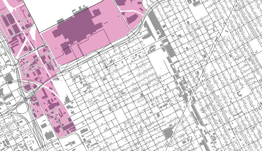
General Industrial


Designing
Circulation along the Greenway
In my Poletown greenway design, I took into consideration three forms of movement; pedestrian, vehicular, and cyclist paths. I took an existing road and turned it into a pedestrian throughway. Through the greenway, I wanted to prioritize pedestrian movement and maximize interactions with the redeveloped Poletown strip.


Farmer’s Market
Redesign Farmer’s Market, Greenway, Shed
In the site analysis, I discovered a former farmer’s market on my site. I leveraged the existing form, “T” shape, to expand it and make it the showcase of the Poletown redesign. I took inspiration from the Easter Market, located in Detroit. I wanted the market to function in all four seasons. Each of the three sheds are fully insulated for winter in Michigan. Each shed is programmed for artists and creatives looking for an open space to design and make. Additionally,the connective structure is best utilized for summer movement between sheds and areas to sell goods. These parts of the building are open to allow for free movement between indoors and outdoors. Access to the greenway from and to the farmer’s market was critical. Space around the farmer’s market was envisioned for food trucks and other vendors as shown in the final site plan.


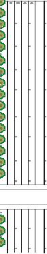
Denver High rise
Mix-use buildings
This academic project was focused around a mixed use high-rise structure in Denver, Colorado. This module instructed students to make a building around a structural core. The specific programming included a wellness center, multiple office floors, aeroponic farming, residential apartments and hotel floors. For my final design, I wanted to create two separate towers that coexisted together to promote community between them and the city of Denver.
Below the ground floor is two floors of parking. Above the ground floor is the wellness center connected by a walkway between the two towers. This is followed by sixteen floors of office space for rental. Alongside eight of the office floors is aeroponic farm space. To allow for viewsheds to the rest of downtown Denver, one tower is taller. The taller tower consists of five floors for a hotel and above it are seven floors for residential apartments. Two transfer levels exist between the office levels and the hotel and the hotel and the residential apartments.


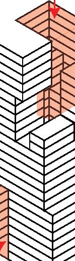


Structure support

Structure Cores


1 East High Street
Oxford, Mixed-use
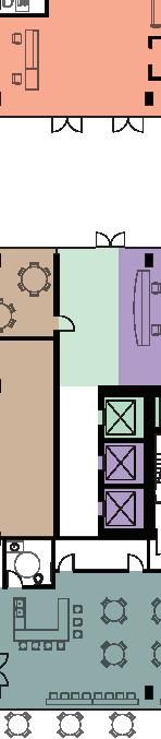
Project is located in Oxford, Ohio at the intersection of Main street and High street in the middle of downtown Oxford. The project is a first story restaurant, two stories worth of office space, and a basement. Students were also asked to incorporate universal design elements into our final design. Studio professor wanted to give students experience creating a full construction set of drawings, including hvac, plumbing, electrical, structural and evacuation plans.
The final design took into consideration the building placement. The high trafficked pedestrian movement drove me to take action at the corner of the building. I created a cutout of the building shape to allow for openness from the street to the building.
First year graduate project


