
MODERN CONSTRUCTION HANDBOOK
SIXTH EDITION ANDREW WATTS Birkhäuser Newtecnic
INTRODUCTION 5
Introduction to sixth edition 6 Governing aspects of design 7 Information layout 8 Design motivation 10 Materials and assembly 11 Performance 13 Realisation of architectural intent through integration of strategies 14 Relation to other design industries 15 Application cases 16 The Modern Construction Series 17 Qualifying comments 17
MATERIALS 19 1 Steel 20 Production 22 Performance 24 Applications 25 2 Aluminium 26 Production 28 Performance 30 Applications 31 3 Copper, zinc, lead 32 Production 32 Performance 34 Applications 35 4 Stone 36 Production 36 Performance 36 Applications 39 5 Glass 40 Production 42 Performance 44 6 Concrete 46 Production 48 Performance 50 Applications 51 7 Fibre reinforced concrete 52 Production 53 Performance 54 Applications 55 8 Ceramics 56 Production 56 Performance 58 Applications 59 9 Timber 60 Production 62 Performance 64 Applications 65 10 Polymers 66 Production 70 Performance 72 11 Material testing 74 Testing of building materials 74
WALLS 77
Trends in facade design 78
Generic wall types 84 Metal 1 Sheet metal 86 2 Profiled cladding 90 3 Composite panels 94 4 Rainscreens 98 5 Mesh screens 102 6 Louvre screens 106
Glass systems 110 1 Stick systems 114 2 Unitised glazing 118 3 Clamped glazing 122 4 Bolt fixed glazing 126 5 Glass blocks and channels 130 6 Steel windows 134 7 Aluminium windows 138 8 Timber windows 142 Concrete 1 Cast in-situ 146 2 Storey height panels 150 3 Small precast panels 154
Masonry 1 Loadbearing walls 158 2 Cavity walls Brick 162 Stone and block 166 3 Cladding 170 4 Rainscreens 174
Fibre reinforced polymers 1 FRP cladding 178 2 FRP rainscreens 182
Timber 1 Timber frame 186 2 Cladding panels 190
ROOFS 195
Trends in roof design 196
Metal roofs
1 Metal standing seam 200 2 Profiled metal sheet 204 3 Composite panels 208 4 Rainscreens 212 5 Metal louvres 216
Glass roofs 1 Greenhouse glazing and capped systems 220 2 Silicone-sealed glazing and rooflights 224 3 Bolt fixed glazing 228 4 Bonded glass rooflights 232
Concrete roofs 1 Concealed membrane 236 2 Exposed membrane 240 3 Planted roof 244
Timber roofs 1 Flat roof: mastic asphalt coverings 248 2 Flat roof: bitumenbased sheet 252 3 Pitched roof: tiles 256
Fibre reinforced polymer roofs 1 FRP rooflights 260 2 FRP panels and shells 264
Fabric systems 1 ETFE cushions 268 2 Single membrane: cone-shaped roof 272 3 Single membrane: barrel-shaped roof 276
CONTENTS
6
STRUCTURE 281
Material systems for structures 282
Elements of structures 284
Braced frames 1 Reinforced concrete 286 2 Steel 290 3 Timber 294
Portal frames 298
Loadbearing boxes 1 Reinforced concrete 302 2 Brick 306 3 Glass 310 Trusses 314 Arches and shells 318 Space grids 322 Floor structures 1 Cast in situ/ cast in place concrete 326 2 Precast concrete 328 3 Steel and steel mesh 330 4 Timber 332 5 Glass 336
Stairs 1 Concrete 340 2 Steel 342 3 Timber 344 4 Glass 346
ENVIRONMEN T 349
Environmental studies for envelopes 350
APPLICATIONS 419
REFERENCES 495
1
Analysis
for
design 1 Solar radiation 354 2 Daylight 358 3 Thermal performance 360 4 Wind 362 5 Solar shading 364 6 Double skin facades 372 7 Natural ventilation 378 8 Thermal mass 380
Low-energy material systems 1 Embodied energy 382 2 Green walls 386
Active design 1 Liquid based heating/ cooling systems 388 2 Mechanical heating/ cooling systems 390 3 Electrical lighting 396 4 Raised floors 398 5 Internal ceilings 400
Support services 1 Sanitation and drainage 402 1 Maintenance and cleaning 404 2 Lifts 410
Performance testing 1 Facade material systems 412 2 Roof material systems 416
Working with industry 420 2 Triangular panels for twisted facades 422 3 Twisted panels with flat glass for curved facades 424 4 Solar shading louvres 430 5 Double-skin facades 434 6 Precast concrete panels for facades of complex geometry 436 7 Exoskeleton facades of complex geometry 440 8 Diagrid structures 442 9 Hybrid systems forming facades of complex geometry 444 10 Opaque cladding interface with full-height glazing 448 11 Complex curved glazed roofs 450 12 Large-scale glazed facades 454 13 Panelisation of complex building surface geometry 456 14 Opaque rainscreen cladding 460 15 Full-height glazing with GRPclad structural frame 462 16 GRC cladding interfaces 464 17 Full-height entrance glazing 466 18 GRP louvres on stick glazing system 468 19 GRC cladding 474 20 Windows in GRC cladding 476 21 Windows and unitised glazing with GRC cladding 480 22 Unitised glazing with GRC cladding 482 23 Complex glazed roofs with supporting steel structure 484 24 Glazed roofs with complex geometry 488 25 Louvres and stick glazing 490
Glossary of terms 496 Authorship 500 Photo credits 501 Index 502
INTRODUCTION
Introduction to sixth edition
Governing aspects of design Information layout
Design motivation Materials and assembly Performance
Realisation of architectural intent through integration of strategies Relation to other design industries Application cases
The Modern Construction series Qualifying comments
This book presents building and envelope technologies as entities independent of previous application; the technologies are instead presented according to their principle material and key characteristics. This is contrary to the traditional method of building component presentation found in existing technical manuals and manufacturer specifications, which commonly focus on the traditional application of each technology. The current available publications focus on the specific application of building technologies for rectilinear buildings; grouping technologies in terms of building type rather than the basic principles which govern them. This approach allows the corresponding current technologies for standard systems to be compared easily. However, it is often not possible to extract the driving principles behind the technology from an examination of its application in buildings alone. Also, the principles and generalised guidelines which made the technology applicable for a certain application may not be applicable to another building technology: therefore, the design of alternative system types incorporating these technologies is restricted.
The materials-based approach specific to this book allows parallels to be drawn between building technologies that are based on the same primary material. The development and use of building technologies are informed mainly by the physical properties specific to each material and the way the material is processed, manufactured or formed for use as a building material. Arranging with respect to material also provides greater freedom for the designer in how the technology is applied in a system. The design is then formed based on the individual technology's characteristics and performance. The approach allows innovative applications of
current technologies to be designed and implemented. To further this book's intent, detailed applications of the technologies in building projects are not provided. Some suggestions are given as to potential applications, but the aim of these example systems is to inspire new designs rather than provide a set method of application. Therefore, the text provides the information required to select and apply the technologies in a way that is flexible; it does not explicitly guide or restrict the designers' use of them. The skill of combining and applying the technologies to a building design project remains with the individual designer, as this requires creativity which is inspired but can not be taught. This and the other books in the Modern Construction Series therefore facilitate the continuation of an innovative design process, enabling complex buildings to be achieved through an economically feasible and sustainable design.
Technical publications of building technologies are most commonly used during the detailed design phase of a building system. The basis for detailed calculations and system design, the early stage designs for a given system are consequently less specific in the choice of materials and systems for structures and facades. This late introduction of the specific facade technology into the design process creates a large disadvantage in terms of maximising system efficiency. A key fact which has been presented in multiple research publications highlights that the value of building performance and associated construction costs are both determined by the early stage design. The design process for buildings usually involves the production of interim reports which provide a snapshot of drawings, calculations and evolving specifications at a given point in time. The integration of technical design early in the design
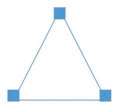
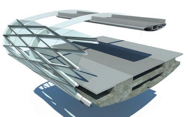
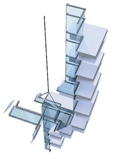
process provides opportunities for the technologies used to inform the design process as well as to inform the design ‘product’. The linking of building systems so that they can interface more easily has long been an aspiration of manufacturers; the current situation is one where few systems coordinate easily with each another (a). Interfaces between different building systems can be extremely complex and difficult to design prior to construction, resulting in laborious onsite fabrication to resolve the interfaces, which restricts the ability to achieve continuous high performance across the whole building and envelope. This suggests that the taxonomy of building systems incorporated in this book should be based on a robust set of genuinely different generic types: these would have to be identified independently of current systems of classification, such as those described in designers' specifications. The structure of architecture-based specifications identifies components and assemblies in interrelated sections, where each sub-item in the assembly is identified independently: such as ‘curtain walling’, which itself comprises several generic external wall types set out in this book. Specifications then link items such as ‘curtain walling’ to their constituent materials of glass, seals, paint finishes and so on under quite different headings. While the system is useful in describing a building for use by a contractor, particularly with regard to national standards including those for performance testing, specifications do not relate to the parts in a way that can be easily used at the design stage in order to understand generic facade assemblies. Therefore, the approach taken in the classification system of the Modern Construction Handbook is to group items in a way known to building design teams: structure, walls, roofs, and environment.
Governing aspects of design
Building system constructions can be thought of as having three governing aspects; the materials and assembly, the system performance and the architectural intent or integration of strategies. All three are interlinked (b) with factors of one aspect often affecting factors in one or both of the other aspects; considering all three aspects is key to a successful design as they form the foundation for the building systems. All aspects can be considered in parallel; due to the interlinked nature, the different constraints and opportunities for the design related to each aspect can have an impact on the constraints and opportunities of the other two aspects. Given the nature of the design process, with the greatest impact on the system design achieved in the initial phase and a potential for design influence that then exponentially decays over the duration of the project, the described approach can be adopted from the initial design stage. This will provide the required impact on the design, allowing the required level of performance and sustainability to be achieved.
This book aims to present current construction technologies and trends, highlighting characteristics relating to the three governing aspects for each topic or system. This is in order to enable the existing technologies to be integrated to form a feasible building system design, which is achieved through the interpretation of the designer. Technologies can be assessed and compared independently of traditional application to allow an advantageous application to be determined, which may not correlate with the traditional applications of the technology. The integration of technologies should be based on the key aspects of materials
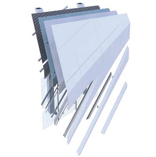
and assembly, performance and architectural intent, rather than previous project applications. This text also demonstrates the shift and continuity between traditionally constructed pre-industrial buildings and the current technologies which can be used to form the mass customised complex geometry buildings of the 21st century. The word ‘complex’ is used to denote geometries which are not rectilinear, and therefore cannot be described by plans and sections which can be extruded in a straight line through the form of the building.
Information layout
The construction of buildings has, historically, been based on a varying relationship between loadbearing structure, walls and roofs, and this forms the basis of classification in this book. In some buildings, the walls, roofs and structure are a single entity, as they are in medieval cathedrals – with the exception of their additional timber roofs, used to protect the structural ceiling. In framed construction, the walls and roofs can be continuous over a single supporting structure: while in many cases of 20th century construction, walls, roofs and structure are quite separate, and are then subdivided within each category to provide a 'collage' form of construction where systems are overlaid in the manner of a visual collage.
The current technologies used in the design of contemporary buildings are presented, grouping the technology systems in distinct chapters covering walls, roofs, structure and environment. The book begins with a chapter on building materials, providing knowledge of the initial processes of forming the materials that
comprise the building technologies, and ends with advanced applications of the systems described in the intermediate chapters, providing insight into the complex systems which can be achieved through the integration of current technologies. The category of materials precedes the technology specific chapters, since an understanding of the physical nature of materials is essential in construction-led architecture. The material properties and characteristics are given in a comparative form to allow the potential materials for a specific technology to be compared and evaluated, based on the key performance factors and required characteristics for a system. The current manufacturing methods for producing construction materials are also detailed, allowing the stages of the manufacturing process to be understood and considered when selecting materials for an assembly with regards to sustainability. The chapter presents how the tectonics of material systems have been used historically and how digital tools are bringing flexibility back into building construction, something which was considered to be too expensive until the arrival of CAD/ CAM (computer aided design/computer aided manufacturing). This return to an almost pre-industrial approach to design allows new buildings to develop a much closer empathy with existing buildings, even if the technologies used are very different. The nonrectilinear nature of some of the material systems allows them to engage more robustly and elegantly with the existing fabric, both pre-industrial and that of 20th century Modernism in architecture.
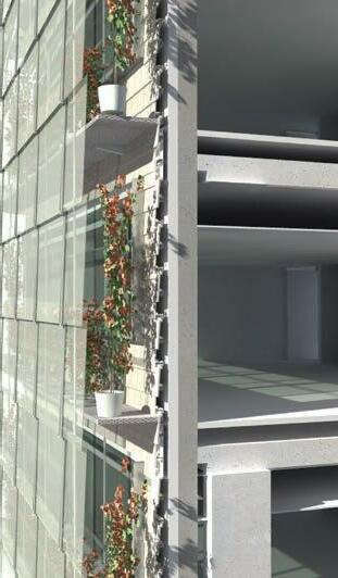
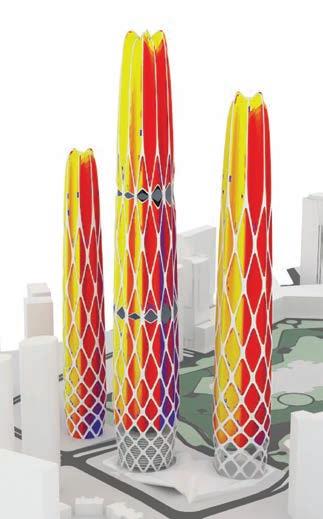
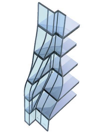
In the current technology sections, the relevant characteristics of each technology are described, covering a wide range of elements from material performance to assembly method; these elements
01 MATERIALS
1 Steel Production Performance Applications 2 Aluminium Production Performance Applications 3 Copper, zinc, lead Production Performance Applications 4 Stone Production Performance Applications 5 Glass Production Performance 6 Concrete Production Performance Applications 7 Fibre reinforced concrete Production Performance Applications 8 Ceramics Production Performance Applications 9 Timber Production Performance Applications
Polymers Production Performance
Material testing
Steel hollow profilesa
Density mild steel 7840 kg/m3 (490 lb/ft3)
Design strength from 275 N/mm² to 900 N/mm² (from 5.7 x 10⁶ to 18.8 x 10⁶ lbf/ft²)
Young’s modulus 210 kN/mm² (4.4 x 10⁹ lbf/ft²)
Coefficient of thermal expansion 11 x 10-6 K-1 (6.1 x 10⁻⁶ OF-1)
Thermal conductivity 45 W/mºC (26 BTU/hr.ft.OF)
Specific heat capacity 480 J/kgºC (0.11 BTU/lbOF)
σNominal stress (MPa)
700
600
500
400
300
200
100
800 ε - Nominal strain (%)
0 100 20 30 40 50 60
Properties and data of structural carbon steelsb Medium
Overview
Cast iron and wrought iron were the forerunners of steel. Cast iron, a brittle material with high compressive strength, came into general use as a building material at the end of the 18th century, while wrought iron was developed some 50 years later. Wrought iron is a more ductile material and has greater tensile strength, making it less susceptible to shock damage. By the end of the 19th century, both materials had been superseded by steel (a)(b)(c). Steel was first produced around 1740, but was not available in large quantities until Bessemer invented his converter in 1856. This device introduced a method of blasting air into the furnace (hence ‘blast furnace’) to burn away the impurities that inhibited the extraction of a purer iron. By 1840, standard shapes in wrought iron, mainly rolled flat sections, tees and angles were available which could be fabricated into structural components, which are then assembled by riveting them together.
c
Comparison with other materials; general properties
In comparison with other materials, steels have the following general properties:
• High ductility (c), deforming long before they fail.
• Lighter than an equivalent structural member in reinforced concrete (d).
• High stiffness (e). High rigidity in both tension and compression.
• High strength in both tension and compression (f)(k).
• Appearance is smooth in sheet form; rougher of texture in rolled sections and castings, even with paint applied.
• High impact resistance.
• Thermal expansion approximately half that of aluminium (g).
• High thermal conductivity (h).
• High electrical conductivity.
• Susceptibility to continuous rusting, excluding weathering steels.
• Low fire resistance.
• Low specific heat (j).
carbon steel stress-strain graphSteel production processa
Production
Steel is an iron-based metal alloyed with small amounts of other elements, the most important being carbon. The three main forms of steel used in the building industry are sections, sheets and castings. First, iron is refined from ores containing iron oxide. The iron oxide is heated in a blast furnace until it is molten, using carbon as a reducing agent. The molten material is poured into moulds to produce pig iron. It is then reheated to remove impurities, including carbon, to make cast iron that has a carbon content of 2.4 to 4 percent. Steel is produced by reducing the carbon content to approximately 0.2 percent, with materials such as manganese and silicon added to halt the oxidation process and stabilise the carbon content. It can be poured when molten to make castings or formed into ingots for later processing of steel elements (a).
Uses and Limitations
Structural mild steels are made in three types called ‘grades’, increasing in design strength from 275N/mm² to 400N/mm² (5.7 x 10⁶ lbf/ft² to 8.3 x 10⁶ lbf/ft² ), varying slightly in different regions of the world. High strength steels can reach design strengths of 800N/mm² (17.6 x 10⁶ lbf/ft²). Since the Young’s Modulus is constant for all these types, the strength of the material increases but the stiffness remains constant. Steel also increases in cost with higher levels of strength, both in the cost of the raw material and in the working of the material. In addition, as strength increases in the material, welding becomes more difficult and consequently more specialised. In some high-strength steels, which undergo heating and quenching during their manufacture, the effects of welding could potentially undo the work of manufacture if sufficient care is not taken. Standard rolled sections are manufactured in the low-to-medium-strength grades, but higher strength steels are
made mostly in the form of plate (b), due to lower demand for their use. Consequently, compound shapes for structural components, such as beams and columns, must be specially fabricated.
Hot rolled process
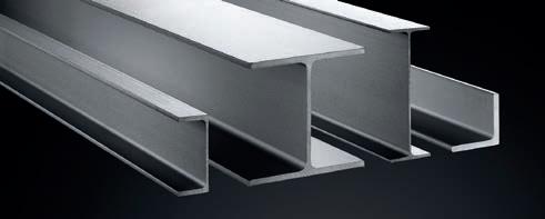
Hot rolling is a mill process which involves rolling (c) the steel at a high temperature (typically over 920° C (1700° F), which is above the recrystallization temperature of steel. When the material is heated beyond the recrystallization temperature, steel can be shaped and formed easily, allowing the material to be formed as large-scale components. Hot rolled sections, such as H, I, L or U profiles (d), are formed using caliber rolls in order to obtain the same cross-sectional shape as that of the rolls. After producing a near cross section such as an H-shape by caliber rolling, the product is finished by a universal mill and an edging mill (e). For example, an H-shaped cross section is formed when the material passes through four rolls, making the universal mill, which is equipped with a pair of vertical rolls and a pair of horizontal rolls, suitable for rolling H-beams. The edging mill is equipped with caliber rolls as shown in the diagram above, and has the ability to adjust the flange widths of individual products. The arrangement of rolls varies with requirements for the specific cross-section of the material, but the process for each profile is very similar.
Hot rolled steel is typically cheaper than its cold rolled equivalent due to the fact that products are often manufactured at source, avoiding the need for steel to be reheated, which is the case with cold rolled steel. As hot rolled steel cools, it shrinks slightly, allowing less control over the size and shape of the finished product when compared with comparable
cold rolled products. Hot rolled products, such as steel bars, are used to make large-scale structural components such as I-beams, box sections and tubes. These are used in situations where precise shapes and tolerances are not a primary requirement.
Cold rolled process
Cold rolled steel is essentially hot rolled steel that has undergone further processing. The steel is processed further in cold reduction mills, where the material is cooled (to room temperature) followed by annealing and/or tempered rolling. This process produces steel with closer dimensional tolerances and a wider range of surface finishes than hot rolled steel. When referring to bar products, the term used is ‘cold finishing’, which usually consists of cold drawing and/or turning, grinding and polishing. This process results in a higher-strength material with four main advantages over hot rolled steel: cold drawing increases the yield and tensile strengths, often eliminating further costly thermal treatments; turning removes surface imperfections; grinding narrows the original size tolerance range; polishing improves surface finish.
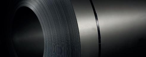
All cold-formed products provide a superior surface finish to those which are hot rolled. Their application suits conditions where tolerances, surface condition, concentricity, and straightness are the major factors. Cold-worked mild steels are also used for much smaller-scale structural components such as lightweight structural framing in metal framed housing and low-rise commercial buildings, as well as in drywall partitioning and in backing walls to facade systems.
Processing
Production of tubes and pipes
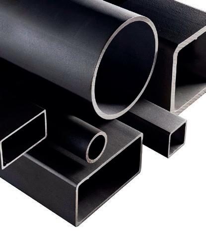
There are two primary types of steel pipe (f); one is seamless and the other has a single welded seam along its length. Each type has a different use. Seamless tubes are typically more light in weight, and have thinner walls. Seamed tubes are heavier and more rigid, with greater consistency in their physical properties, and are typically straighter. Typically, seamed tubes are used in instances where the pipe is not put under a high degree of stress. Characteristics of pipe size can be varied during manufacture, such as diameter, as can the wall thickness of the pipe also be varied during production. The specific steel grade used will affect the strength and flexibility of a pipe. Other controllable characteristics include length, coating material, and finish.

Extrusion
It is possible to extrude steel to form complex sections (g), but this currently has only limited applications due to the high pressure needed to extrude the material. Aluminium is a much softer material, making it easier to extrude. Even when aluminium is alloyed with other materials such as bronze, the extrudable size of sections drops dramatically. Extrusions in steel cannot exceed shapes that fit into a circle approximately 150mm (6”) in diameter. This is too small for structural sections, but their smooth appearance makes them suitable for components such as stiffeners in curtain walling, to provide a fin that is visually more refined than an I-section or a tee. Currently, it is still far easier to roll steel sections than to extrude them.
 Beam blank Hollow billet Heating Mandrel
Hot extrusion Seamless pipe
Breakdown mill Universal mill Universal mill Edging mill Die
Steel coilb
Steel open section beamsd Rolled steel open section beam processe
Steel rolling processc
Steel hollow section beamsf Hot extruded steel seamless pipe productiong
Performance
Degradation of the material
The effects of corrosion, oxidation and degradation both change the appearance of steel and can reduce the performance of the material, even leading to its failure if maintenance is not carried out as scheduled. Where steel components are coated with plastics or paint coatings, steel can undergo surface discolouration, paint delamination, solvent swelling and embrittlement of the material itself. Steel can be attacked as a result of water-based corrosion or be oxidised at higher temperatures.
Protections
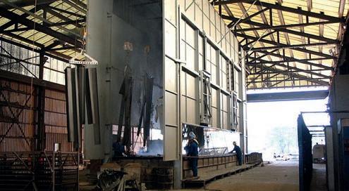
Galvanising is a zinc coating that is corrosion-resistant, applied to the steel in a hot dip bath or as a flame spray (a). Galvanising occurs after fabrication of steel components to cover all the welding and drilling. This process can cause distortion of smaller steel components, so may not suit all types of fabrication. The appearance of galvanising when new is a mottled shiny grey, turning to a dull grey with weathering as the zinc oxidizes. Its visual appearance is often not suitable for exposed structural steelwork or cladding in buildings, where paint coatings are more common.
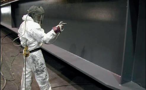
Paint coatings
Paint coatings are applied in layers, typically as follows:
The first coat, the primer, is applied directly onto the cleaned steel surface (b). This coating helps to create a better surface finish in the final layer by providing a high amount of adhesion for coats applied subsequently. Primers are applied directly to steel to provide resistance to corrosion.
Intermediate coats are applied in order to build up the overall film thickness of the paint coating. Thicker coatings provide a longer life in the service of a steel component, particularly when exposed to the atmosphere. Intermediate coats are specially designed to enhance overall protection and, when highly pigmented, decrease permeability to oxygen and water.
The finish coat provides the final appearance and surface resistance of the paint system. Depending on the conditions of exposure, the paint build-up provides the first line of defence against the effects of weather, sunlight, exposure and condensation.
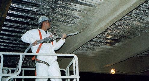
Stripe coats are coats of paint that are applied locally to welds, fasteners and external corners. Their purpose is to create an increased thickness of coating at edges and corners, where paint has a tendency to contract and thin upon drying. Paint coatings can also provide fire protection through the use of intumescent paint (c).
Stainless steel
Stainless steel is an alloy of steel which contains between approximately 11 and 25 % chromium, together with nickel in some types, giving it properties that are distinct from carbon steels; the main one being a high resistance to corrosion without the need for an additional coating. Since the material is considerably more expensive than carbon steels, stainless steel is most commonly used in small building components and in cladding panels where durability is a primary requirement (d).
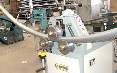
Galvanized dipping processa Fire protection coatingc Paint coatingb Manufacture of curved stainless steel panelsdMandrel tube bending machinee Curved beamsf
Curved beam
Reference surface
Relative position of beam surface is the same as reference surface
Applications
Standard steel beam elements
Sizes of standard beam and hollow sections range in depth from between 21.3mm and 1036.3mm, and in width from 21.3mm to 508mm, as shown in Eurocode design tables. These standard sizes vary slightly between countries as a result of the requirements of each market. The length of a beam element will depend on the cross section, thickness of steel, transportation and factory limitation, but standard steel sections can be manufactured in lengths from 12 metres to 20 metres.
Stainless steel
For conditions where the environment is highly corrosive, the use of stainless steel is extremely suitable, as the material is highly resistant to corrosion and usually requires no coatings. Stainless steels have higher fire resistance than carbon steels. Although the material develops a thin oxide layer that protects it from further corrosion, different grades of stainless steel are available to suit the severity of exposure from polluted urban to maritime to rural environments. When using stainless steel there is the risk of bimetallic corrosion at the junction of stainless steel and carbon steel when they are used together.
Working with the material
Sections and sheets can be curved to small radii (f). Bolting and welding are the most common methods of joining sections, sheets and castings. Steel can also be sawn and drilled. An essential characteristic of steelwork is that it will continue to rust if surface protection is not provided. When drilling or cutting the material, the newly-exposed surface requires protection, which is particularly important if the material has already been factory coated.
Twisted element
Unrolled geometry
Cold bending of steel sections
Tubes, angle sections, channels, I-sections, channels and box sections can be curved by the process of cold bending. This method uses mechanical force to push a steel section against a die, forcing the element to take the shape of the die (e). An alternative method is induction bending, which is used mainly for large section tubes. This technique uses induction to heat up a short length of pipe quickly, resulting in minimal deformation of the profile of the curved section.
Specially fabricated steel components
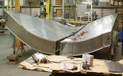
Some shapes of steel section can be difficult to achieve with conventional processing methods. Specially fabricated steel components are made using advanced computational modelling and digital fabrication tools. A recent example of the application of this method is the structural frame of the Beijing National Stadium, designed by architects Herzog and de Meuron. A significant challenge, from the point of view of fabrication, was to use steel box sections for structural beams of varying cross-sectional shape, which also resulted in complex geometries at the junctions between the structural members. The outer faces of the steel box sections were maintained as always being parallel to the base surface, which resulted in twisting box sections (g), made from flat steel plate which was curved to form each box section. Consequently, all surfaces of those box sections remained developable, that is to say that they were made from flat sheet. The individual faces of the box sections were curved to shape, then assembled and welded together to form complex structural sections that could not be made by conventional means (h).
02 WALLS
Trends in facade design Generic wall types
Metal
1 Sheet metal 2 Profiled cladding 3 Composite panels 4 Metal rainscreens 5 Mesh screens 6 Louvre screens
Glass systems 1 Stick systems 2 Unitised glazing 3 Clamped glazing 4 Bolt fixed glazing 5 Glass blocks and channels 6 Steel windows 7 Aluminium windows 8 Timber windows Concrete 1 Cast in situ 2 Storey height panels 3 Small precast panels Masonry 1 Loadbearing walls 2 Cavity walls Brick Stone and block 3 Cladding 4 Rainscreens
Fibre reinforced polymers 1 FRP cladding 2 FRP rainscreens Timber 1 Timber frame 2 Cladding panels
Trends in facade design
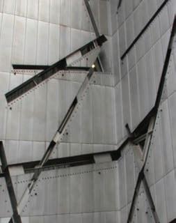
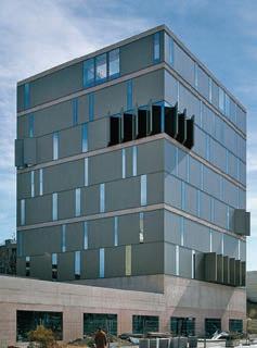
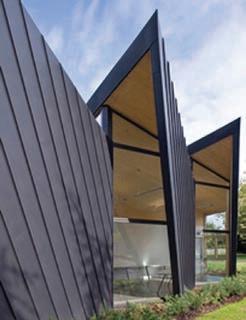
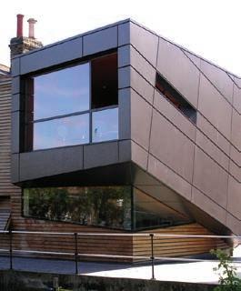
Metal
d
Significant changes in the design of external walls in recent years have increased thermal performance and solar control, provided greater water tightness and demonstrated a reduction in air infiltration rates through wall assemblies, and a limited return to natural ventilation where possible as a partial alternative to mechanical ventilation in larger scale buildings. These changes have led to a shift in design priorities. During the late 1980s, the increased use of thermal insulation brought with it an increased risk of condensation occurring in cladding assemblies. This condensation can occur both inside the panel and on the inner face of wall assemblies. A result of technical development has been the avoidance of condensation. The increased use of natural ventilation, both as air supply and as a means of cooling buildings at night, has had an effect on cladding design, particularly in the integration of opening lights and louvered slots in panels. The arrival of the deep plan building, with distances of up to 18 metres between external walls, has led to a need for greater levels of daylight entering a building. This, in turn, has increased the need for both solar shading and glare control. In addition, the cost of photovoltaic cells, which can generate electricity when exposed to sunlight, has reduced considerably over the past 15 years. As a result, these are increasingly used in large-scale applications for buildings. These energy-led changes in wall design have generated a range of technical developments which have changed the emphasis of facade design. The architectural interest in the expression of structure in buildings has been replaced by an interest in energy conservation. This is largely because the effect of additional layers of external insulation, blinds, shading and so on often renders the structure almost invisible.
Thermal insulation
The use of thermal insulation has increased dramatically over the past 15 years, with wall assemblies achieving a U-value of 0.25 W/m²K as a minimum standard. This compares with a typical level of 0.6 W/ m²K in the early 1980s. There is an accompanying risk of interstitial condensation occurring within a wall assembly from damp air that penetrates a wall assembly where it may condense and cause damage. In addition to dew point calculations undertaken at the design stage to
assess risk, vapour barriers are added to halt the passage of damp air into wall assemblies where interstitial condensation can occur, typically on the warm (in winter) side of the insulation. Alternatively, the internal construction can be ventilated in order to draw away damp air.
Condensation can also occur on the inner face of a wall in temperate climates, typically where there is continuity in a material from the outside to the inside of a building that allows a direct passage of heat or cold through the external envelope. When this ‘thermal bridging’ occurs, condensation can form on the inner face of the wall where it can drip down, resulting in inconvenience to building users and damage to the construction. Thermal bridges are avoided by providing a separating component in a low conductivity material, called a ‘thermal break’, that prevents heat or cold from being transmitted between the inside and outside. An example of its use is in glazed walling, where the construction of a frame of mullions and transoms requires some continuity of metal from outside to inside. Plastic spacers of low thermal conductivity are positioned to provide a thermal break that also enhances the structural integrity of the construction.
Two generic types of thermal insulation have emerged for use in wall systems: rigid foam and flexible quilt types. The rigid foam type is made typically from either a polymer-based board such as polyurethane foam. Since both are non-hygroscopic or ‘closed cell’, they can be used in situations where the thermal insulation can become wet without any significant reduction in its performance. Closed cell insulation is also used to form the structural core of metal-faced composite panels (b) as well as in facing the inner leaf of cavity walls. In contrast, flexible quilt is made typically from a mineral fibre quilt, cut to fit voids in panel frames more easily than board, but its lack of rigidity makes it unsuitable for use externally. While heavier insulation helps to provide a more rigid, water resistant material, the lighter, less rigid types provide better thermal insulation. As a result, the choice of core is a balance between the needs of rigidity and thermal performance.
Rainscreens
Rainscreen cladding is a development of the rainscreen for pressureequalised walls researched during the 1960s. It was found that water commonly penetrates joints in walling because of the outside air pressure being greater than that inside the joint. Water arriving by a variety of means, mainly gravity, wind and capillary action, was able to penetrate the outer seals of joints. The introduction of rainscreen framing systems and panel systems overcame this problem by creating an outer ‘screen’ layer or seal that stops most of the water entering the joint, but ensures that the air pressure in the void behind the panel or joint is the same as that outside it (c). Rainscreen systems have three essential functions:
- To protect joints in the cladding assembly from the worst effects of windblown rain.
- To provide a decorative screen for a waterproofing system whose appearance is not suitable for an external wall. The same principle applies to roof cladding.
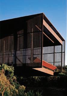
- To provide an outer protective layer to thermal insulation fixed on the external face of a high thermal mass construction such as concrete.
Drained and ventilated systems
There has been a move away from ‘hermetically’ sealed systems, which rely entirely on a single weatherproof outer skin, towards ‘drained’ systems. This is common to virtually all sealed facade types. Drained systems accept that the air pressure differences between the outside of the wall and the inside will allow small amounts of rainwater to penetrate the outer seal. This effect can be countered through two means; the water can be drained away within the metal framing that supports the cladding panels, and the pressure differences can be equalised by ventilating the system by providing slots at drainage points, usually set at the base of the wall. This ensures that water is not trapped within the panel framing, nor is the water discharged at vulnerable points in the construction where staining and damage can occur on the face of the panel. The use of ventilation within an assembly, on the external side of a thermal insulation layer, allows cladding systems to
dry out once water has penetrated. Wherever water or water vapour penetrates a material in a wall or roof, it is stopped from travelling further by the vapour barrier or waterproof membrane. At this point, it can be difficult for the water to dry out. A void is sometimes formed at the vapour barrier to allow the water to evaporate and prevent the adjacent material from being damaged. This is particularly important in the case of timber, where eventual rot can occur. The development of drained systems accepts that externally applied seals will leak small amounts of water and that it is better to design for that eventuality. Even systems with a single outer seal can be designed to drain away water within their construction.
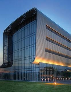
Use of materials in facade systems
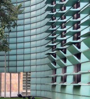
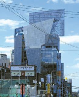
The different material systems for facades are very much influenced by the particular material chosen. The essential issues in working with each material in facade assemblies are described in the following paragraphs.
Metals
Metals used in facade systems are based mainly on sheets, extrusions and castings. Thin sheet metal is made in narrow strips up to 1000mm wide, making it necessary to form simple, reliable joints at close centres when joining the material together to form a weather-tight surface (d). This is done by folding the metal together at the edges to form a continuous seam that projects from the wall surface, making it difficult for water to penetrate from outside. Standing seams are economic to make, but need to be done with care to avoid uneven joint lines (g). Because it is difficult to achieve crisp lines with this method, which relies on site-based workmanship rather than the use of workshopbased machines, the uneven ‘oil canning’ appearance can be accepted as an uneven texture forming part of the design. Because sheet metal used in facades is thin in order to fold it and work it, it requires support from underneath. The support surface conveniently forms a base for a backing waterproof layer which is needed behind sheet metal since it is unable to exclude rainwater. Sheet metal can be welded
Trends in facade design
b
a
Architect:
c Bolt fixed glazing system: Tower Bridge House, London, U.K.
Architect: Rogers Stirk Harbour + Partners
d
Architect:
together to form a continuous waterproof sheet material, but thermal expansion needs to be allowed for standing seam joints that prevent the material from deforming as the metal expands. The number of joints on a facade can be reduced by increasing the size of the metal sheet being used. Profiled metal sheet can be formed into very long lengths, and into widths of up to around 1500mm. Joints between sheets are formed by lapping sheets both horizontally and vertically with sealant set between adjacent sheets to provide a waterproof joint. This allows the sheet material to span between the supports of a framed supporting structure behind, rather than needing continuous support. Fixing profiled sheet to the supporting structure requires fixings that penetrate through the outside of the sheet to the inside, which presents a potentially weak point for waterproofing. This penetration through the material by fixings is avoided in standing seam sheet metal. Fixings for profiled sheet are made to be fixed easily, using a self-tapping screw, which has a waterproof washer on the outside and a drill bit on the front of the screw to make a hole. The self-tapping sealed screw is essential to the success of profiled metal sheeting, and corner trims and folded copings in the same material ensure the watertightness of junctions.
Sheet metal has been developed in recent years to be bonded to closed cell insulation, since both materials are used very economically in combination, so that the stiffness of insulation is combined with the watertightness and durability of metal. The successful bonding of rigid insulation to thin metal has been essential to the success of composite metal panels. These panels are joined with tongue-and-groove joints, usually on two sides. While this is a reliable joint, the joint on the opposite two sides is usually less accomplished, normally being a butt joint sealed with silicone, with an additional top hat metal profile to enhance the seal. Four sided tongue-and-groove jointed panels are more difficult to fix and more difficult to remove if damaged. The tongue-and-groove joint incorporates a void in the centre that allows water to drain down. The basic principle with sealing joints between composite panels is to ensure that any water entering the joint will drain down an internal cavity that drains water away to the outside at the bottom of the panels.
Glass
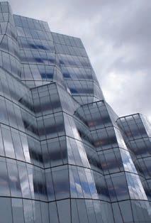
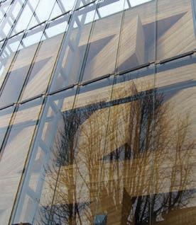
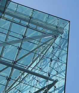
Glass in facades is supported either by edge frames or by fixing it at points. Glass facades are beginning to be glued together without any metal fixings, but the design of such structures is in its early stages. Frames supporting the glass must both hold the glass in place and prevent rainwater from penetrating the seals. Difficulties in providing reliable rubber-based seals have led to the ‘pressure equalised’ or ‘drained and ventilated’ frames discussed earlier in this section. Water penetration in frames has traditionally been caused by capillary action where the air pressure inside the frame becomes higher than the outside atmospheric pressure, drawing water into the frame and potentially causing leaks. The problem of capillary action has been overcome, not by increasing the pressure on the seal between frame and glass, but by ventilating the void inside the frame so that any water that penetrates the outer seal is drained away safely down the cavity to the outside. The drained and ventilated cavity provides a second line of defence against rainwater penetration through the outer seal. The principle of pressure equalisation, with an inner chamber behind an outer seal, is essential to current framed glazing systems (a). An alternative method of glazing is to avoid a frame entirely in order to increase the effect of transparency given by the glass. In point fixed glazing, the glass is only held at at a few points by small brackets or bolts. Glass is clamped together with plates, and bolted together through the joints between the glass (b). Alternatively, holes are drilled in the glass and the sheets are held by bolts secured directly through the holes in the glass without plates, using discs or a countersunk profile to the bolt connector (c). Joints are sealed with silicone in a single line of defence. While the material does not suffer problems of water being drawn through, it as happens with clamped rubber seals, good workmanship is essential to the success of these single seals.
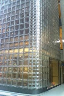
Walls built in glass blocks are constructed by bonding the blocks together with either a cement-based mortar or silicone (d). Because blocks are set with continuous vertical and horizontal joints, giving them their characteristic appearance, panels are structurally inherently
System design
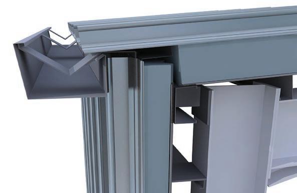
The main difference between profiled metal cladding and the continuously supported type is that profiled sheet can span 3-5 metres between supports, depending on the (sectional) profile used (2). The profile depth provides the material with rigidity in one direction, allowing it to be fixed directly to a structural frame rather than requiring the continuous support of an additional substrate. Its profile allows the sheet to be gently curved in one direction during installation on site , with the material still lapped on all edges regardless of its orientation. Profiled sheet can be curved along its rigid length by crimping in the factory, usually to form curved corner pieces for horizontally-set cladding, or curved eaves pieces for vertically-set cladding (11). Proprietary systems offer a range of curved components as well as 90° corners where short lengths of sheet are welded to form a crisp corner panel. The wide range of profiles available, from small wave profiles to deep profiled sections, gives a wide range of visual effects.
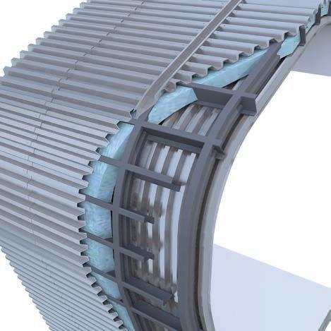
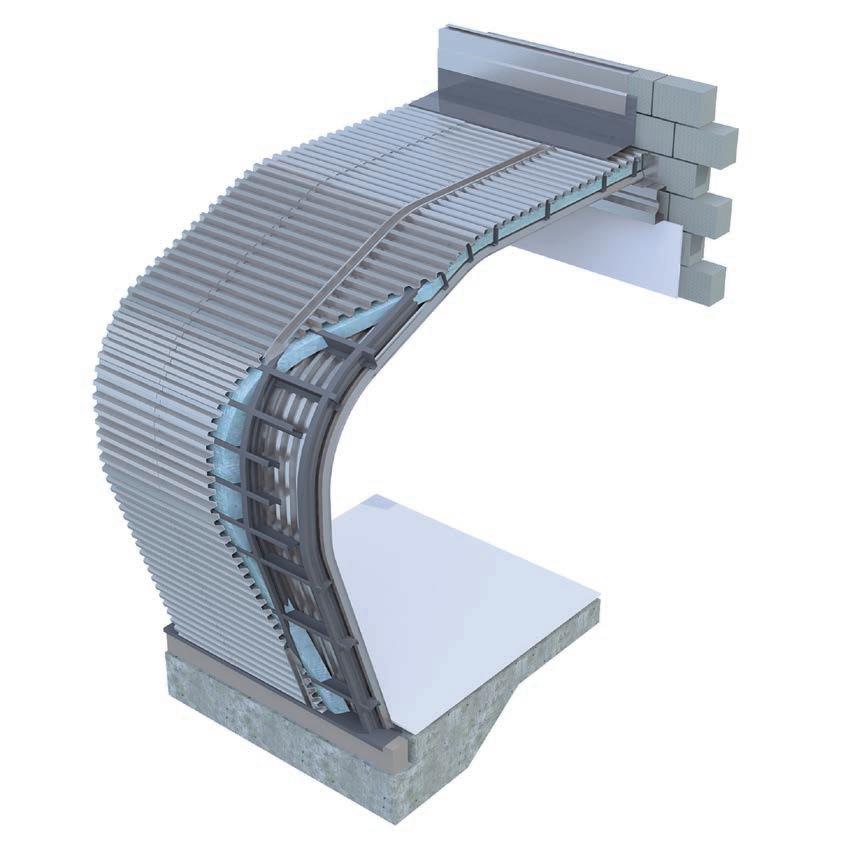
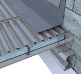
Profiled metal cladding has developed from its initial application in industrial buildings in the 1970s to wider architectural applications. This material system uses a single metal, either steel or aluminium, for the complete cladding of, typically, manufacturing or storage buildings which have large shallow-pitched roofs and a relatively small facade area in relation to that of the roof. The all-metal envelope evolved, in an architectural sense, with the introduction of curved eaves and a concealed gutter (12) with walls and roof appearing to be a continuous
form. The profiled metal sheet was set with the ribs running from top to bottom of the roof and continued down the facades in the same alignment. As its use in facades developed, profiled metal cladding was used horizontally rather than vertically, in order to curve the wall profile when seen in section (c), and at different angles in order to introduce an expression of complex geometry.
As a material system, the profiled nature of the material requires continuity of the profile from sheet to sheet, making it difficult to create visual offsets in the setting out of the material. Where a change of orientation or direction is needed by the design, a projecting cover strip or recessed shadow gap joint is needed which creates a break in the system. Since the shape of the profile cannot be varied in regular manufacture, the lines of the sheet and visible joints at geometric changes in the system dominate its appearance. In common with standing seam metal, profiled metal sheet does not have windows and doors that form part of the material system, though these items can be made in the same material and finish. Because windows and doors are made by different manufacturers, it is important to ensure either colour matching at the fabrication stage, or contrasting colours/finishes that work together visually. Where the inner lining of the wall is also formed in profiled metal sheet (typically flatter, and sometimes perforated for acoustic performance), a similar approach is taken.
Metal 2: profiled cladding
Vertical section 1:10. Profiled cladding wall construction
3D view showing wall and roof assembly
(Below) 3D view showing gutter detail in profiled cladding wall construction
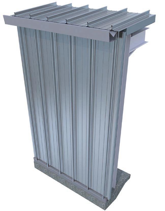
3D views showing standing seam wall assembly at parapet and ground floor interface conditions
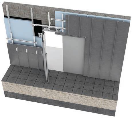
3D view showing standing seam wall assembly and interface with ground floor slab
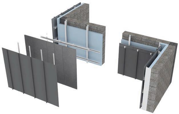
3D exploded view showing standing seam wall assembly
Cover strip profile
Metal sheet
Metal standing seam
Breather membrane/vapour barrier
Thermal insulation
Blockwork backing wall
Floor finish
Drywall/dry lining
Z-section steel fixing rails
Floor slab
Curved eaves profile
Concealed gutter
Exposed gutter
Adjacent structural wall
Cladding fixing frame
Metal flashing Steel structure
Standing seam clips
System details
Vertically-set sheeting requires folded metal flashings at the top and bottom of the wall to form parapets and cills (1), as well as corners, usually made from flat sheet. Some manufacturers provide crimped flashings for corners in order to provide visual continuity between adjacent facades. Where flat sheet is used at corners, plastic or foambased filler pieces form part of the system to close the gaps between the profiled sheet and the flat metal flashings that are usually set onto the face of the profiled sheet. The visual impact of these filler pieces needs to be assessed within the design. Horizontally-set sheeting can be formed as continuous cladding with barely visible joints resulting from lapping the sheets (3). Alternatively, the profiled sheet can be divided into bays, formed with vertical joints closed with cover strips or with recessed pressed (top hat) sections.
At roof level, parapets are formed with a pressed metal coping with another flashing beneath (h). A metal flashing is used to close the gap between the roof deck and the parapet upstand where the roof is also clad in profiled metal sheet. Where only a low upstand is required, as at the gable, a folded flashing is fixed to the roof surface to form a sealed edge. A metal coping flashing is then fixed to the upstand and is folded down the face of the external wall. Although the thermal insulation forming part of the wall construction is made continuous with that of the roof, the void in the parapet is usually filled with thermal insulation to avoid high temperature variations between the outside and inside of the construction (5).
The void behind the sheet is filled with thermal insulation which requires a vapour barrier on its internal (warm in winter) face (4). The internal lining of the wall can be in any material, though dry lining or an additional layer of profiled metal sheet is typical (8). Some manufacturers have proprietary lining sheets in metal which are flatter than the external profiled sheet to suit the typical requirements of internal finishes.
Openings for windows and doors are sealed with metal flashings that can be determined as much by visual requirements as by the needs of weatherproofing. Window openings often have wide cover strips around the edges of the opening to provide a full weather-tight seal which forms a highly visible part of the design.
Corners can be made from either externally set cover strips or by recessed corner flashings to suit the design. The recessed version requires careful installation of the cladding sheets on site in order to achieve the relatively narrow corner joint widths. Cover strips usually have their edge folded back to provide a crisp line around the profile. Folded flashings are usually in two parts, with an inner seal between cladding and window, and an additional outer flashing which is sealed with silicone back to the profiled metal.
Although proprietary systems are available, it is easy to adapt these systems where the facade fabricator makes flashings to suit individual requirements. Principles of details are well understood by fabricators and complete proprietary systems are not always required.
Metal 3: composite panels
Details
Composite panel Panel fixing to primary or Secondary structural steelwork
Polysulphide or silicone-based seal
9 10 11 12 13 14 15 16 17
Window frame Roof parapet Gutter
1 2 3 4 5 6 7 8 a
Special panel highlighting floor level Floor slab Roof Steel column Curved corner panel Special corner panel
System design
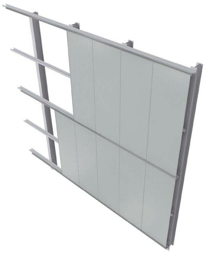
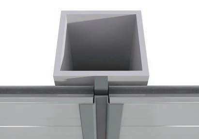
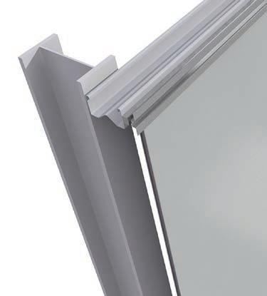
This material system provides a complete wall assembly in a single panel form, sometimes with integral windows and doors that interlock with the regular panels (a). Panels consist of an inner core of rigid thermal insulation (6) onto which a thin metal sheet is bonded to each side (4)(5), with a specially formed profile around the edges of the panel that forms a weathertight connection with adjacent panels (c). This material system is made as a complete proprietary system, each with varying levels of interchangeability and surface finish in relation to their cost. Their main visual advantage is the smoothness of the panel faces that form a complete system with integral panels for corners, parapets and window openings. Their main technical advantage is in providing a complete wall construction in a thin panel which is also highly thermally insulated. Panels are typically made in widths of 1100mm to 1400mm to suit the manufactured width of metal coil (7), but are long; up to around 15 metres, where transportation of the panels becomes a primary consideration of their size.
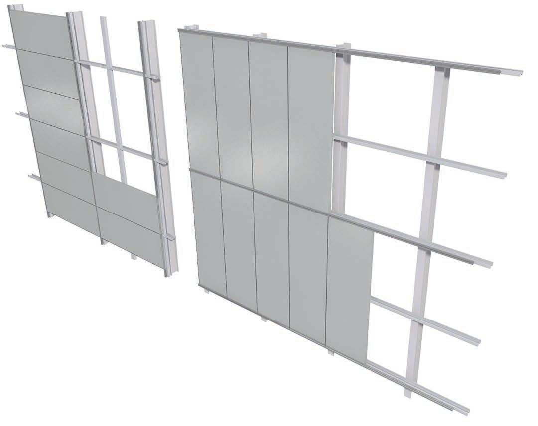
Panels typically have interlocking joints on two sides, forming an integral part of their fabrication, with panels being set either vertically or horizontally (8). Joints are typically formed to avoid a thermal bridge from inside to outside by creating a small break between inside and outside layers of metal, and are shaped to ensure that rainwater runs back out of the panel. Joints between panels at their short ends, where there is no interlocking joint, are butt jointed and sealed with cover strips. Panel
systems are also used with interlocking joints on all four sides, and these are usually made in sizes that can easily integrate doors and windows which also form part of proprietary systems.
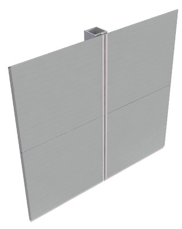
Vertically-set panels that interlock on two sides are usually storey height. Where panels are stacked over more than one storey, the horizontal joints between panels are usually sealed with metal flashings. Panels are supported on horizontal rails (2), typically at floor level to allow a floor-to-ceiling panel arrangement without intermediary structure that would be visible from inside the building. Horizontally-set panels that interlock on two sides are stacked one above the other, with tongue and groove horizontal joints which usually contrast visually with the vertical joints, which have wider sight lines in order to accommodate a metal cover strip, a rubber-based gasket, or a combination of them (b). Since vertically set panels are typically separated by the flashings, vertical joints can be discontinuous, allowing windows to be set in specific locations on a floor-by-floor basis, with each floor having its own arrangement of composite panels that is not aligned with those on the floor below. This has given rise to the use of mixed panels, set both vertically and horizontally, in a tiled arrangement rather than the exclusive use of the rectilinear grid seen until recently.
In four-sided interlocking panels, joints usually incorporate an inner chamber set between an inner and outer seal in order that the system
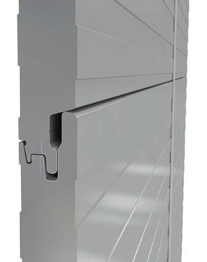
Composite panel Panel fixing to primary or secondary structural steelwork
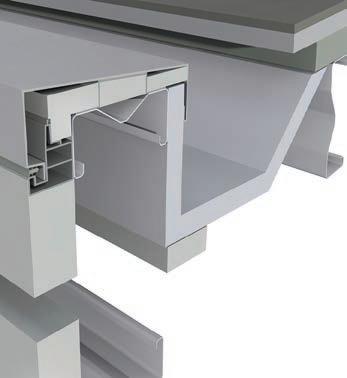
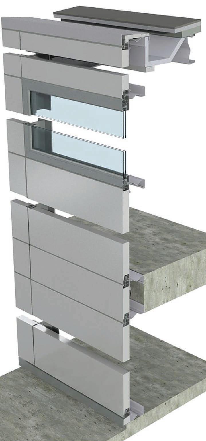
Polysulphide or silicone-based seal
Outer metal facing Inner metal facing Inner insulation core Metal capping Interlocking fixing Window frame Roof parapet Gutter
Special panel highlighting floor level Floor slab Roof Steel column Curved corner panel Special corner panel Double glazing
07 REFERENCES
Glossary of terms Authorship Photo credits Index
The glossary of terms here is aimed to explain words used in the con text of this book. These are not intended to be general definitions and should be used accordingly. Topics are arranged in alphabetical order.
Butt joints
These are a contemporary type of joint where two materials are brought together and sealed with a different material such as silicone, as in an external wall. Traditionally, joints in walls have been formed by some form of lapping or interlocking of materials, as in the corners of window frames. Butt joints have the advantage of allowing movement to occur in the joint, as where adjacent panels are supported separately. An example is the use of silicone sealant between bolt fixed glazed units, where double-glazed units move independently and may experience con siderable amounts of movement if secured to a structure that allows higher deflections than frames, such as cable net structures. An essen tial requirement of most butt joints is to ensure that there is sufficient surface on either side of the joint for the sealant to seal against, allow ing it to stretch in several directions without losing adhesion.
Capped systems
Glazed walls or roofs which are fixed to a continuous framing system on all sides are referred to as being ‘edge restrained’. Since most panels in glass or metal, for example, have four sides, these systems are gen erally called ‘four edge restraint’ systems, with the panels being held in place by pressure plates. Since the pressure plates have visible screws which are not always aligned neatly, an additional cover cap is set on top of the pressure plate. The cap is made in extruded aluminium and is coated, typically with a colour to match any adjacent metal panels or doors. Such systems are called ‘capped systems’ to differentiate them from those which have a silicone seal on the outside, such as ‘toggle’ glazing and ‘silicone bonded’ glazing, where only a silicone strip is visible from the outside. Sometimes a capped joint is used in one direction on a glazed wall, while a silicone seal is used in the opposite direction.
Cavity wall
This form of construction was developed from the 1920s onwards in brick construction as an alternative to thicker loadbearing walls, which were both unreliable in their ability to keep out rainwater and vapour as well as being more expensive to construct. The cavity wall divides the wall into two halves, or ‘skins’. The outer skin is the weather barrier, and is assumed to become completely soaked during a rainstorm. The inner leaf is not in contact with the outer leaf, so it remains generally dry. The two skins are joined together with cavity wall ties, designed to encour age water in the cavity from dripping off the ties and down the cavity rather than being carried onto the face of the adjoining inner skin. The cavity wall has developed by setting thermal insulation either within the cavity, on the outer face of the inner skin, or within the inner leaf itself.
Cladding
This term refers to non-loadbearing facade systems which are applied to a building envelope in a way which is independent of the building structure. Cladding may even be used to give a completely different expression to the building suggested by either the building structure or the organisation of spaces within the building. This independence of cladding from its supporting structure has been exploited by many con temporary architects to create textures and geometries which accept this independence of the technology of the building envelope, and work with the opportunities provided by the non-loadbearing nature of clad ding. Since the primary structure of the building is set behind the clad ding, the external envelope can be configured to give precedence to other design considerations as primary forms of architectural expres sion, such as daylight, solar control and the visual expression of indi vidual spaces within a building without direct reference to the structural frame.
Composite materials
These have been developed to mix two or more different materials together in order to benefit from the strengths of each so as to over come the weaknesses inherent in one or other of the materials. In wood, for example, where a length of timber can span only as long as it can be cut from a tree, lengths of timber sections can be increased significant ly by gluing strips or particles of timber to make board material. This combination uses the benefits offered by timber of lightness in weight and ease of working the material with increased size and greater stabil ity to reduce the effects of moisture movement. Reinforced concrete can be regarded as a composite material, with steel reinforcement pro viding strength in tension which is lacking in regular concrete. GRP, or glass reinforced plastic, is a mixture of resins providing – conceptually at least – compressive strength, with glass fibre giving tensile strength.
Curtain walling
This refers historically to glazed wall systems which were ‘hung’ in pan els or as a metal framework into which glass panels were set. While the concept is clear, these systems are not always hung in the manner of a curtain, and do not always span from floor to floor. Contemporary curtain walling is described as being either ‘stick’ systems, ‘unitised’ systems, or ‘panelised’ systems (explained under separate headings). Consequently, the term curtain walling is not referred to in this book as it is too generic, with ‘glazed walls’ used instead to allow the primary material to take precedence. Curtain walling was developed in the years following 1945, primarily in the United States where it was a practical way of enclosing tall buildings without the need for lifting heavy materi als such as stone and brick high up, where they were slow and difficult to manage, making them far less economical in industrialised countries.
Double skin facades
These are essentially two skins of external wall which provide a thermal buffer in winter and natural ventilation in summer. The thermal buffer ensures that solar gain in winter months can be used to heat a build ing, while in summer, windows at high level can be opened into a void between inner and outer skins without experiencing the effects of wind gusts. Double skin facades can vary from 1000mm in width, with two walls separated by a maintenance walkway, to a thickness of 300mm, where the double skin is set within a single wall construction, typically as unitised panels. With the wider version, comprising two walls set apart, the cavity can be ventilated form the outside, either with open joints or with controlled louvres. Thin double skins are ventilated from inside the building, sometimes actually linking the void within the wall to the mechanical ventilation system.
Eaves
These are junctions between the top of an external wall and the under side of a sloping roof, which typically overhangs the wall. Where the external wall is made as a cladding system rather than a traditional loadbearing wall, the relative movements of wall and roof need to be taken into account in the weather tightness of the junction. There is also a need for continuity of thermal insulation from wall to roof, some times providing ventilation into the roof space and sometimes providing a complete seal from wall to roof. As an interface between primary ele ments of a building which are usually performing in quite different ways, using quite different forms of construction, eaves junctions require the lapping of the waterproofing for the roof to form a continuity with that of the wall. As an interface, an eaves detail usually requires one of the systems of wall or roof to take precedence from a visual point of view, so this becomes an additional requirement of their design.
Embodied energy
This is the amount of energy required to construct a building or part of a building. No specific standards can be applied at this stage, as an essential component in the energy required to construct a building is the delivery of materials to site, which can vary enormously, but which favour as local a sourcing of materials as possible. In practice this can be difficult to agree on, as it needs to be established how far up the supply chain to go when calculating the energy required to make pri mary materials for a building. In the case of polymers, for example, the dependence on oil from different parts of the world being transported can create complicated scenarios for calculation. Timber is considered to have zero embodied energy as a material, but the energy used to fell, cut and transport the material is much higher; though not as high as that for the metals used in fixings which allow the timber to be made useful as a building material.
In-situ cast concrete
This method of working with concrete, also called cast-in-place con crete, is based on forming the material on site using formwork that is set up specifically for the casting process, before being moved to the next stage of casting. The method can be used to create large-scale concrete structures or walls. An important consideration is the form work, which is used increasingly as a kit of parts that can be moved and reassembled quickly for the next part of the work. If the concrete is to be a visible part of the construction, as in the case of columns or external walls, the provision of joints and junctions with adjacent ele ments needs to be considered carefully prior to starting on site. Since the casting of concrete reveals very closely the texture of the formwork from which it is cast, the choice of formwork board size, or tube size for columns, is an essential part of the design of the building, and is consid ered at an early stage of the design.
Lapped joints
This is the traditional method of forming junctions between materials in external walls. In order to ensure that water runs off timber boards, for example, the material is ship lapped, where one board is set over the other. More generally, this principle applies in tiled and slated roofs, and in brick walls where openings are formed so as to lap the external wall around window frames. Where render is used on top of masonry walls, the render forms, effectively, a lap between wall and window. Lapped joints are used in contemporary construction where a butt joint is either not appropriate in terms of its exposure or appearance, or alternatively where ventilation is required, as in rainscreen panel systems and roof coverings. An essential aspect of lapped joints is that they are oriented in a direction that ensures rainwater will run off the joint in a downward direction while allowing ventilation in the upward or lateral direction.
Membranes
These are single-layer materials made in large sizes, typically 1000m to 2000mm in width and in long lengths, supplied in rolls. They are made primarily from polymers, and have the advantage of being pos sible to bond or weld together, often by heat rather than by naked flame, making them easy to install on site. Their use is mainly as reli able waterproof or vapour-proof layers to large areas of wall or roof which experience relatively little thermal movement. Though reliable, they are relatively fragile unless designed specially for external use, as is the case with thicker, tougher roofing membranes. Mostly, however, membranes are required to be concealed beneath other materials to protect them from the effects of the sun and from suffering accidental damage, such as being walked upon for example. Membranes are usu ally fixed at points on their underside in order to avoid penetrating the membrane.
Openings
This book shows examples of details around openings as they are often at the interface of different systems, or components from different sys tems. Windows and doors, for example, do not have obvious ways of being fitted into walls when a very watertight and airtight performance is required. Since facade systems are often developed and tested to quite different standards and with the intention of forming a complete building envelope as a single material system, combinations of two sys tems are dealt with on a project-by-project basis. As windows and doors are often designed within a single system, it is essential to understand the visual impact that they make on a facade, as well as how they can be accessed for cleaning and maintenance. Openings are required to be assembled in a particular order if made from different materials or systems which can influence their appearance, so the sequence of construction is a consideration.
Parametric design
This is an approach to the design of a building, or part of a building, based on the idea of setting ‘parameters’ that can be changed dimen sionally, while making other parts of the design ‘fixed’ which cannot be changed. This principle can be applied to the geometry of a set of floor slabs, for example, which may be allowed to change in one direction only, or be used for a set of components which might be changed. This approach suits geometrically complex or large-scale projects where the time required to rebuild the model would be uneconomical. Because parametric design software allows the design to make changes quickly, it allows the designers to try changes to see what happens to an overall building form, for example. This allows the behaviour of the component or building geometry to be understood, sometimes linking floor areas to a building geometry.
Panelised system
This is a general term covering large-scale panels used primarily for external walls. Their use is in prefabricated wall systems where a build ing is required to be assembled on site quickly, or where the specific site does not make it easy to undertake complicated work; mainly where access is restricted. Where unitised panels in glazed walls are typically around 1500mm wide, panelised systems can be made up to around 7000mm long, depending on their weight, but are typically delivered to site on trailers, so that transportation is an important consideration in their design. These panels may comprise a mixture of systems, such as metal framed backing walls with windows installed, or even precast concrete panels with masonry fixed or forming an integral part of the panel. They are finding use as waterproofed or vapour-proofed backing walls which can be installed quickly on site while the outer skin of the wall is applied later. This allows the building to become watertight at an earlier stage of construction.
Parapets
These are traditional elements of buildings which still form a prominent part of contemporary design. Parapets are formed when an external wall projects up in front of the base of the roof construction, requiring rainwater to be drained into a gutter behind the external wall rather than in front of it. This makes it essential to draw the rainwater down the pipes which are typically set outside the building rather than inside, where they can be difficult to access for maintenance and can be sus ceptible to damage, causing leaks. Parapets are detailed so as to form a gutter between wall and roof that can fill to capacity without the risk of leaking back into the building. Since parapet gutters can become blocked as a result of the outlet being accidentally covered, the design of these junctions, as well as the provision of overflows to the outside, are essential considerations in their design. The coping, or durable cov ering set on top of the parapet, has some visual presence on the facade and can be seen as a termination of the top of the building.
Point fixed glazing
This is a recent development that originated with the clamped glazing systems of the 1960s, used mainly as store-front glazing at that time. The technique comprises either bolt-like fixings set near the corners of the glass, or clamps set on both sides of the glass along the edges of the glass, but not necessarily at their corners. An essential part of their design is to ensure that the glass is supported so that it can move in order to avoid putting additional stress into the glass. These systems are typically designed in conjunction with a manufacturer or facade designer who can ensure that the design is suitable both in relation to its supporting structure and for fabrication. Clamped glazing has become more popular in recent years since it is more economical than the bolt fixed method, as clamps can be set between the joints rather than requiring glazed units to be drilled to accommodate the bolt fixing.
Precast concrete
This material is an alternative to in-situ cast (or cast-in-place) con crete. An essential aspect of precast concrete is that it can be used for structures, facades, roofs and interior building components, making the understanding of how the material is used an essential aspect of designing with the material. Because of the weight of concrete and the high amount of material required for its use in construction, its use as prefabricated components requires careful consideration, particularly in expected tolerances in its assembly, which can require wider gaps than those required in other materials. Although precast concrete is used for staircases, for example, these components are often covered up by finished work and so are not revealed. Consequently, the choice of precast concrete over in-situ cast concrete may not be of primary interest to the designer in such applications. Where the use of precast concrete will be of concern is where the material is visible, requiring careful attention to finish; mainly in terms of colour consistency and
texture; as well as how the formwork will leave traces of the pouring method that may or may not be required in the finished work.
Prefabrication and site-based work
The choice between buildings constructed mainly on site or off site in a workshop or factory is based on issues primarily of cost and qual ity, though it also has to do with increased specialisation in construc tion. Projects of ambition often require specialist construction skills to undertake the construction. Such specialists are usually set up with their own working environment rather than being based on a succes sion of building sites. While prefabricated elements and systems are required to be assembled or set into position on site, this environment is too temporary for many specialists, who require a specific planned work environment for them to be effective both as an organisation and in order to produce work of high quality. Quantities of what can be trans ported to site are usually limited by the capacity and weight allowance of a trailer as well as storage facilities on site. However, some building work is more effectively undertaken on site, using the site as a work shop and storage facility for components. Structural frames and floor slabs in large-scale construction are still mostly site-based, though the amount of prefabrication is increasing.
Rainscreens
These are facade and roof panel systems which allow small amounts of rainwater to enter the joints between panels and be drained down through the framing back to the outside, either at each floor level or at the lowest level of the system. The term was first used for curtain wall ing, where leaks in earlier forms of curtain walling were overcome not by attempting to exclude any water penetration, but by accepting that it is easier to ensure the water drains away safely when it penetrates joints. The term, in general use, is applied more to open joints in panel systems, typically metal, timber and terracotta than to glazed curtain walls. When used in this context, panels in these materials are gener ally fixed to a framing system which is secured to the building structure. A separate backing wall is typically used to provide thermal insulation and a waterproof layer. Rainscreen panels have grown in use as a visu ally refined finish to economical backing walls.
Stick system
This is a method of constructing glazed walls on site from framing and glazed units. Stick glazing is often used in complex arrangements of curtain walling and for smaller projects. Larger projects such as apart ment buildings often have many different conditions in their design on the external envelope, which would require many types of unitised panel that are both uneconomical and difficult to install. Smaller projects do not have a sufficiently large envelope to make unitising panels economi cal and are usually stick built regardless of their level of complexity. The advantages for designers are mainly the flexibility of design, which does
not need to be made modular to suit repeated panels, and the nar rower size of joint widths, which is usually 50mm to 70mm depending on project requirements. Stick systems can also be combined effec tively with supporting steel frames such as those for atrium structures and double skin facades. Where steel frames are used, the aluminium extruded box section on the internal side of the framing can be omitted, allowing the front part of the stick system to be fixed directly to the sup porting steelwork, which would typically also be in box sections.
Thermal bridging
This is also called ‘cold bridging’ but can occur in hot thermal conditions as well as cold conditions. Essentially, the design of different systems of wall and roof construction is gradually being developed to reduce thermal transmission through the build-up. Some parts of the system can perform considerably worse than others, creating a ‘bridge’ for the passage of heat or cold which is prevented elsewhere in the system. In glazed walling, for example, the thermal performance of the framing is significantly less than that of the glazed panels, and is improved by using a ‘thermal break’ so that the high thermal transmission of the frame is ‘broken’ with a polymer-based component set between inside and outside. The thermal break may be a separating strip or may form an integral part of the construction, as is the case with aluminium framing to glazed walls.
U-value and thermal insulation
The U-value of a construction is a measure of the thermal transmis sion through the material, with systems of lower U-value having higher levels of thermal insulation. The U-value takes into account the thermal transmission of all the layers of construction that make up the wall, so walls of different build-up in section require separate U-value calcula tions. U-values can be used in calculating the rate of heat flow of spaces in the building, but are separate from the effects of solar gain through glazing, which may also cause thermal transmission. Consequently, double-glazed units have a Low-E coating and vacuum in the cavity to provide thermal insulation, while a separate solar control coating pro vides protection against the effects of solar gain.
Unitised system
This is a prefabricated method of making facade panels, typically for glazed walls. Its advantage is primarily one of reduced cost for facades with considerable repetition resulting in few panel types; but another advantage is the use of silicone bonding, allowing frames to appear slim on the outside, and for opening lights to have their frames concealed internally. Applying silicone on site in stick systems can be very difficult to achieve due to the time needed, as well as the avoidance of dust around the edges of the bonds.
Authorship & photo credits
This book has been a team effort involving members of Newtecnic in London. Drawings were modelled and rendered by the Newtecnic team. The book was designed by Yasmin Watts. The text is by Andrew Watts. The text and overall content of the book was updated with contributions from Howard Tee and Yasmin Watts.
David Marold is Acquisitions Editor at Birkhäuser Verlag GmbH in Vienna. He has driven this book from a set of basic layouts to a completed book. He has a passion for books and their design, ranging from their wider content to the quality of print paper, to the overall reader experience.
Andrew Watts is an architect and engineer; the author of the Modern Construction series of textbooks. He specialises in the architectural and engineering design of large-scale buildings of complex form. Andrew is a founding director of Newtecnic. He is a Fellow of three UK engineering institutions in recognition of his engineering-based designs; the Institution of Civil Engineers; the Institution of Engineering Designers; the Institution of Engineering and Technology. Andrew holds charterships in the UK for architecture and engineering from the Royal Institute of British Architects and the Institution of Engineering Designers. In the US, he holds an ASCE membership.
Yasmin Watts is a sculptor, architect and creative director of Newtecnic, leading the exploration of links between sculpture, architecture and public art. She is a founding director of the company. Yasmin is focused on creating sculptures in public spaces in the built environment; the fusion of architecture and sculpture has been a key driver in the work behind all the projects shown in this book. She is a registered architect in the UK and is a Fellow of the Royal Society of Arts. Yasmin is continuing her research with the Royal College of Art.
The author would like thank Bettina R. Algieri for the content and production editing of this book. The author would also like to thank Alun Brown for the task of proofreading the text.
Newtecnic have produced volumes on contemporary building technology which provide reference material for engineering and architecture students and professionals around the world. The Modern Construction Series is published by Birkhäuser Verlag GmbH. In addition, the Facades Technical Review, from RIBA Publications was published in spring 2007.
Newtecnic is an architectural and engineering design company that undertakes the architectural design and engineering design of complex and ambitious construction projects, and associated building envelope systems, for use on its own projects. In partnership with the Engineering Department of Cambridge University, Newtecnic’s R&D team has developed, analysed and tested new facade components and assemblies for use on live projects.
The company is led by Andrew Watts, Howard Tee and Yasmin Watts. The Modern Construction series forms an essential part of their research work which informs the design of projects.
The Newtecnic approach, based on research from first principles, allows the company to achieve architectural and engineering design solutions for the complete building, from concept to production information, including engineering and architectural design for structure, facades and the internal environment. The method used is based on technical and visual concepts that are supported by analysis, modelling, geometry and coordination. Newtecnic’s work ranges from conception and the development of design concepts to detailed design and engineering analysis for fabrication when working
for contractors. With 3D BIM, Newtecnic designs models that become highly evolved during the design process. Components of these BIM models, with accompanying text and images to illustrate design processes, form the basis of the Modern Construction Series. The engineering and architectural design skills of Newtecnic allow the company to communicate, through the Modern Construction series, the key issues of 21st century building engineering and design. Newtecnic are holders of The Queen’s Award for Enterprise and are ranked in the top three of New Civil Engineer 100 Companies of the Year 2019
Newtecnic are currently undertaking the architectural design and engineering design of a large-scale technology-oriented and visitor-based project in Nevada, USA.
Photo credits
Photographic images are credited per page. All other photographs have been provided by courtesy of Newtecnic Ltd.
P79 e. Sun Tower Office Building, Seoul. Photo: YoungiIl Kim.
P81 f. Matsunoyama Natural Science Museum, Japan. Photo: Katsuhisa Kida P199 h. Single membrane roof. Photo: Architen Landrel Associates Ltd. P199 f. ETFE roof.
Photo: Vector Foiltec Ltd. P283 p. Lerner Hall Student Center, Columbia University, New York, U.S.A. Photo: Lydia Gould. P284 c. Museum of Contemporary Art, Los Angeles, U.S.A. Photo: Yasuhiro Ishimoto.
Further reading
The other books in the Modern Construction Series, which are based on the systems of construction described in this book, are suggested for further reading.
Modern Construction Case Studies, 2nd edition Birkhäuser, 2019
Modern Construction Envelopes, 3rd edition Birkhäuser, 2019
Modern Environmental Design, 1st edition Birkhäuser, 2022
Modern Structural Design, 1st edition Birkhäuser, 2022
P285 f. Jewish Museum, Berlin, Germany. Photo: Studio Daniel Libeskind.
P396 Kitakame Canal Museum, Japan. Photo: a. Kengo Kuma and Associates. P396 b. Furniture House, Yamanashi Prefecture, Japan. Photo: Hiroyuki Hirai.
P397 c. International Housing Exhibition, Fukuoka, Japan. Photo: Kwano, courtesy of Office for Metropolitan Architecture. P397 d. Freshwater Pavilion, Neeltje Jans, Holland.
Photo: Lars Spuybroek, NOX Architects.
P404 a. Offices, DaimlerChrysler Projekt, Potsdamer Platz, Berlin, Germany.
Photo: Robert Peebles.
P408 e. Swiss Re building, London, U.K. Photo: Robert Peebles. P410 c. 88 Wood Street, London, U.K. Photo: Robert Peebles.
A
Working with Industry 420
Authorship 500
Aluminium 26
Aluminium windows 138
Arches and shells 318
B
Bonded glass rooflights 232
Bolt fixed glazed walls 126
Bolt fixed glazed roofs 228 Brick 56
Brick loadbearing boxes 306
Brick cavity walls 162
Braced frames 286
C
Cast-in-situ concrete walls 146
Cast-in-situ concrete floors 326
Ceramics 56
Clamped glazing 122
Complex curved glazed roofs 450
Complex glazed roofs with supporting steel structure 484
Composite panel roofs 208
Concealed membranes 236
Concrete 46
Concrete braced frames 286 Composite panels 94
Copper, zinc and lead 32
D
Daylight 358
Double skin facades (principles) 372
Double skin facades (application) 434
E
Elevators 410
Embodied energy 382
Environmental studies for envelopes 350
Electrical lighting 396
ETFE cushions 268
Exoskeleton facades of complex geometry 440
Exposed membranes 240
F
Fabric systems 268
Fibre reinforced concrete 52
Flat roof:
Mastic asphalt coverings 248
Bitumen-based sheet 252
Floors 398
FRP cladding walls 178
FRP panels and shells 264
FRP rooflights 260
FRP rainscreens walls 182
Full-height entrance glazing 466
Full-height glazing with GRP-clad structural frame 462
G
Generic wall types 84
Glass 40
Glass blocks and channels 130
Glass loadbearing boxes 310
Glass floors 336
Glass roofs 220
Glazed roofs of complex geometry 488
Glass systems 110
Glossary of terms 496
GRC cladding 474
GRC cladding interfaces 464
Green walls 386
Greenhouse glazing and capped systems 220
GRP louvres on stick glazing 468
H
Hybrid systems forming facades of complex geometry 444
I Internal ceilings 400
Introduction to fourth edition 4
L
Large-scale glazed facades 454
Lifts 410
Liquid based heating/ cooling systems 388
Loadbearing boxes 302
Louvres and stick glazing 490 Louvre screens 106
M
Maintenance and cleaning 404
Masonry cavity walls 162
Masonry cladding 170
Masonry loadbearing walls 158
Masonry rainscreens 174
Material systems for structures 282
Material testing 74
Metal mesh screen walls 102
Metal composite panels roofs 208
Metal composite panels walls 96
Metal louvres roofs 216
Metal louvre screen walls 106
Metal profiled cladding walls 90
Metal profiled sheet roofs 204
Metal standing seam roofs 200
Metal sheet walls 86
Mechanical heating/ cooling systems 392 N
Natural ventilation 378
O
Opaque cladding interface with full-height glazing 448 Opaque rainscreen cladding 460
P
Panelisation of complex building surface geometry 456
Performance testing 412 Photo credits 501
Pitched roof tiles 256
Planted roof 244 Polymers 66 Portal frames 298
Precast concrete panels for facades of complex geometry 436 Precast concrete floors 328
Profiled cladding walls 90 Profiled metal sheet roofs 204
R
Rainscreen roofs 212
Rainscreen walls 98
Realisation of architectural intent 14
Reinforced concrete boxes 302
S
Sanitation and drainage 402
Sheet metal walls 86
Silicone-sealed glazing and rooflights 224
Single membrane: cone-shaped roof 272 barrel-shaped roof 276
Small precast panels 154 Solar radiation 354 Solar shading 364 Solar shading louvres 430
Space grids 322
Stairs: Concrete 340 Steel 342 Timber 344 Glass 346 Steel 20 Steel mesh floors 330 Steel frames 290 Steel windows 134 Stick glazing 114 Stone 36
Stone and block walls 166
Storey height precast 150 Structure and envelope 8 Support services 404
T
Thermal mass 380
Thermal performance 360
Timber 60
Timber cladding panels 190
Timber floors 332 Timber roofs 248
Timber frames 294 Timber frame walls 186 Timber windows 142
Triangular panels for twisted facades 422
Trends in facade design 78 Trends in roof design 196 Trusses 314 Twisted panels with flat glass for curved facades 428
U
Unitised glazing 118 Unitised glazing with GRC cladding 482
W
Wind 362 Windows and unitised glazing with GRC cladding 480 Windows in GRC cladding 476
Acquisitions Editor: David Marold, Birkhäuser Verlag, Vienna, Austria
Content & Production Editor: Bettina R. Algieri, Birkhäuser Verlag, Vienna, Austria
Layout: Yasmin Watts, London, England
Cover design: Floyd Schulze Proofreading: Alun Brown, Vienna, Austria Printing and binding: Holzhausen, die Buchmarke der Gerin Druck GmbH, Wolkersdorf, Austria
Library of Congress Control Number: 2022943382
Bibliographic information published by the German National Library The German National Library lists this publication in the Deutsche Nationalbibliografie; detailed bibliographic data are available on the Internet at http://dnb.dnb.de.
This work is subject to copyright. All rights are reserved, whether the whole or part of the material is concerned, specifically the rights of trans¬lation, reprinting, re-use of illustrations, recitation, broadcasting, reproduction on microfilms or in other ways, and storage in databases. For any kind of use, permission of the copyright owner must be obtained.
ISBN 978-3-0356-2494-6 Hardcover edition ISBN 978-3-0356-2495-3 Softcover edition e-ISBN (PDF) 978-3-0356-2496-0
© 2023 Birkhäuser Verlag GmbH, Basel P.O. Box 44, 4009 Basel, Switzerland Part of Walter de Gruyter GmbH, Berlin/Boston
1st Edition 2001: SpringerWienNewYork
2nd Edition 2010: SpringerWienNewYork 3rd Edition 2013: AMBRA V
4th Edition 2016: Birkhäuser Verlag 5th edition 2019: Birkhäuser Verlag 9876 www.birkhauser.com
