
54 minute read
Testing is tattooed on my forehead
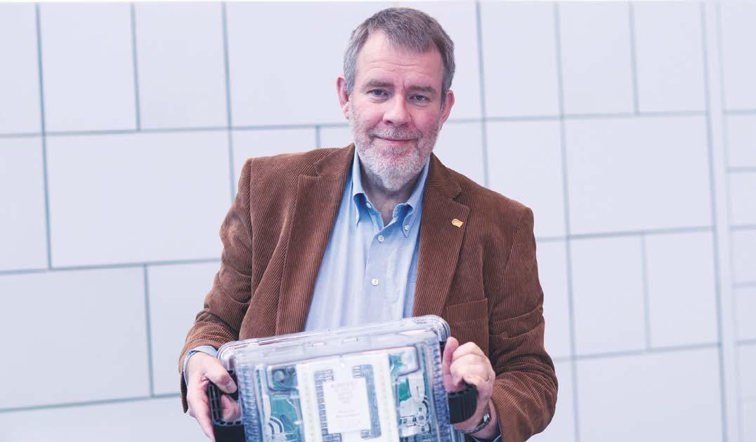
When he was a student, he didn’t have the slightest interest in chips, let alone in testing them. Now, Erik Jan Marinissen is an authority in the IC test and design-for-test arena and even teaches on the subject.
Advertisement
Paul van Gerven
Last year, when Erik Jan Marinissen heard that his papers at the IEEE International Test Conference (ITC) had made him the most-cited ITC author over the last 25 years, he didn’t believe it. “I had skipped a plenary lunch session to set up a presentation that I would give later that day when passers-by started congratulating me. For what, I asked them. They explained that it had just been announced that I’m the most-cited ITC author over the past 25 years. Well, I thought, that can’t be right. Of course, I had presented a couple of successful papers over the years, but surely the demigods of the test discipline – the people I look up to – would be miles ahead of me,” tells Marinissen.
Back at home, Marinissen got to work. He wrote a piece of software that sifted through the conference data to produce a ‘hit parade’ of authors and papers. The outcome was clear: not only was he the most-cited author, but his lead over his idols was also actually quite substantial. ITC being the most prominent scientific forum in his field, there was no question about it: Marinissen is an authority in the test and designfor-test (DfT) disciplines (see inset “What’s design-for-test?”).
Once he was certain there had been no mistake, Marinissen felt “extremely proud. I’ve won some best-paper awards over the years, but they typically reflect the fashion of the moment. What’s popular one year, may not be anymore the next. My analysis confirms this, actually: not all awarded papers end up with a high citation score. Being the most-cited author shows that my work has survived the test of time; it’s like a lifetime achievement award.”
Diverse and interesting
Verifying the calculations that entitled him to a prestigious award might be considered an instinct for someone who has dedicated his life to checking whether things work correctly, but Marinissen and testing weren’t exactly love at first sight. “As a computer science student at Eindhoven University of Technology, I didn’t have much affinity with chips or electrical engineering. We CS students used to look down on electrical engineers, actually. Electrical engineers are only useful for fixing bike lights, we used to joke. I’m sure they felt similarly about us, though,” Marinissen laughs.
Testing seemed even less appealing to Marinissen, for reasons he thinks
What’s design-for-test?
A modern chip consists of millions or even billions of components, and even a single one malfunctioning can ruin the entire chip. This is why every component needs to be tested before the chip can be sold. It’s turned on and off, and it needs to be verified that it changed state.
The hard part is: you can’t exactly multimeter every transistor as you’d do with, say, a PCB. In fact, the only way to ‘reach’ them is through the I/O, and a chip has far fewer I/O pins than internal components. Indeed, the main challenge of testing is to find a path to every component, using that limited number of pins.
This task is impossible without adding features to the chip that facilitate testing. Typically, 5-10 percent of a chip’s silicon area is there just to make testing possible: adding shift-register access to all functional flip-flops, decompression of test stimuli and compression of test responses, on-chip generation of test stimuli and corresponding expected test responses for embedded memories. Design-for-test (DfT), in its narrow definition, refers to the on-chip design features that are integrated into the IC design to facilitate test access.
Colloquially, however, the term DfT is also used to indicate all test development activities. This includes generating the test stimulus vectors that are applied in consecutive clock cycles on the chip’s input pins and the expected test response vectors against which the test equipment compares the actual test responses coming out of the chip’s output pins. Chip manufacturers run these programs on automatic test equipment in or near their fabs.

are still true today. “If you don’t know much about the eld, it may seem like testers are the ones cleaning up other people’s messes. at’s just not very sexy. For IC design or process technology development, it’s much easier to grasp the creative and innovative aspects involved. Even today, I very rarely encounter students who have the ambition to make a career in testing from the moment they set foot in the university.”
It took a particular turn of events for Marinissen to end up in testing. “I wanted to do my graduation work with professor Martin Rem because I liked him in general and because he worked part-time at the Philips Natuurkundig Laboratorium, which allowed him to arrange graduation projects there. Like most scientists in those days, I wanted to work at Philips’s famous research lab. But, to my disappointment, professor Rem only had a project in testing available. I reluctantly accepted, but only because I wanted to work with the professor at the Natlab.”
“I soon realized how wrong I was about testing. It’s actually a diverse and interesting eld! You need to know about design aspects to be able to implement DfT hardware, about manufacturing to know what kind of defects you’ll be encountering and about algorithms to generate e ective test patterns. It’s funny, really. Initially, I couldn’t be any less enthusiastic about testing, but by now, it has been tattooed on my forehead.”


Stacking dies
After nishing his internship at the Natlab in 1990, Marinissen brie y considered working at Shell Research but decided that it made more sense to work for a company whose core business is electronics. He applied at the Natlab, got hired but took a twoyear post-academic design course rst. Having completed this, Marinissen’s career started in earnest in 1992.
“At Philips, my most prominent work was in testing systems-on-chip containing embedded cores. A SoC combines multiple cores, such as Arm and DSP microprocessor cores, and this increases testing complexity. I helped develop the DfT for that, which is now incorporated in the IEEE 1500 standard for embedded core test. When the standard was approved in 2005, many people said it was too late. ey thought that companies would already be set in their ways. at wasn’t the case. Slowly but surely, IEEE 1500 has become the industry default.”
Marinissen is con dent the same will eventually happen with another standard he’s helped set up. He worked on this after transferring


from Philips, whose semiconductor division by then had been divested as NXP, to Imec in Leuven in 2008. He actually took the initiative for the IEEE 1838 standard for test access architecture for three-dimensional stacked integrated circuits himself. He chaired the working group that developed the standard for years until he reached his maximum term and someone else took the helm. The standard was approved last year.
“Stacking dies was a hot topic when I was hired at Imec. Conceptually, 3D chips aren’t dissimilar from SoCs: multiple components are combined and need to work together. By 2010, I’d figured out what the standard should look like, I’d published a paper about it and I thought: let’s quickly put that standard together. These things always take much longer than you want,” Marinissen sighs.
His hard work paid off, though. Even before the standard got its final approval, the scientific director at Imec received the IEEE Standards Association Emerging Technology Award 2017 “for his passion and initiative supporting the creation of a 3D test standard.”
Flipping through the slides
As many researchers do, Marinissen also enjoys teaching. He accepted a position as a visiting researcher at TUE to mentor students who – unlike himself when he was their age – take an interest in DfT. At an early stage, he also got involved with the test and DfT course at Philips’ internal training center, the Centre for Technical Training (CTT). “Initially, most of the course was taught by Ben Bennetts, an external teacher, but I took over when he retired in 2006. I remember having taught one course while still at NXP, but not a single one for years after that – even though Imec allowed me to. There just wasn’t a demand for it.”
“Then, in 2015, all of a sudden, I was asked to teach it twice in one year. Since then, there has been a course about once a year.” By then, the training “Test and design-for-test for digital
Credit: Imec
integrated circuits” had become part of the offerings of the independent High Tech Institute, although, unsurprisingly, many of the course participants work at companies that originate from Philips Semiconductors. “Many participants have a background in analog design or test and increasingly have to deal with digital components. I suppose that’s understandable, given the extensive mixed-signal expertise in the Brainport region.”
“I might be the teacher, but it’s great to be in a room with so much cumulative semiconductor experience. Interesting and intelligent questions pop up all the time – often ones I need to sleep on a bit before I have a good answer. It’s quite challenging, but I enjoy it a lot. As, I imagine, do the students. I’m sure they prefer challenging interactions over me flipping through my Powerpoint slides.”
From begrudgingly accepting a graduation assignment to sharing his authoritative DfT expertise in class – the young Erik Jan Marinissen would never have believed it.
www.acalbfi.nl/5G

5G NOW!


5G 4G 3G
Global Coverage GNSS Receiver Onboard SIM Industrial Grade
AirPrime®
EM9190
5G NR Sub-6 GHz and mmWave for next-generation IoT solutions
LOWER LATENCY HIGHER CAPACITY HIGHER SPEED

5G – Evolutionary changes and new business opportunities!
Renewable Energy
Medical Transportation
Industrial & Connectivity
Agriculture
Public Safety Insurance

Supply Chain Management

Need more information? +31 40 2507 400 sales-nl@acalbfi.nl
consult. design. integrate.
SIGNIFY AND ESI CONNECT ON CLEVERLY CONNECTING SMART LIGHTING


Smart lighting systems bring the potential for big cost and energy savings. The public-private Prisma project has produced tooling to streamline their development and deployment. Partners Signify and ESI (TNO) are now building on their successful collaboration to put the results to broad practical use.
Nieke Roos
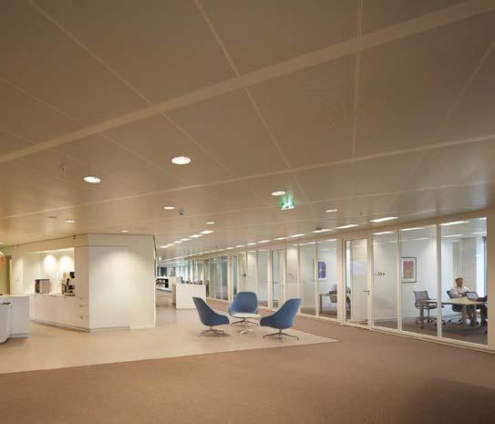
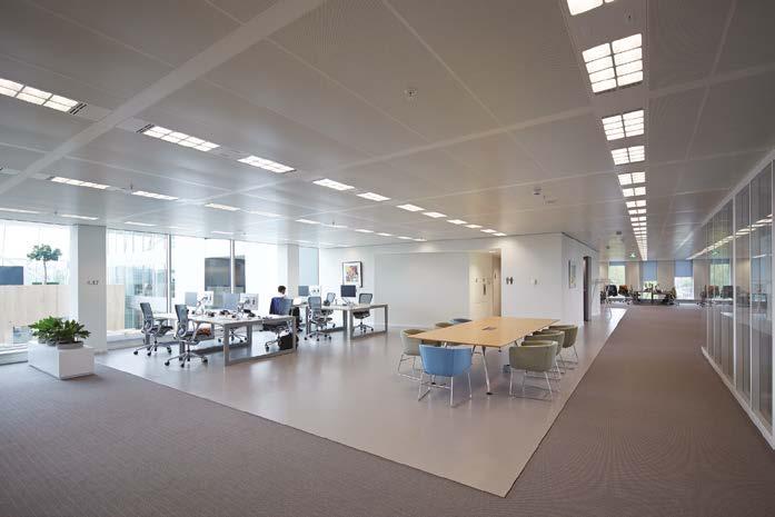
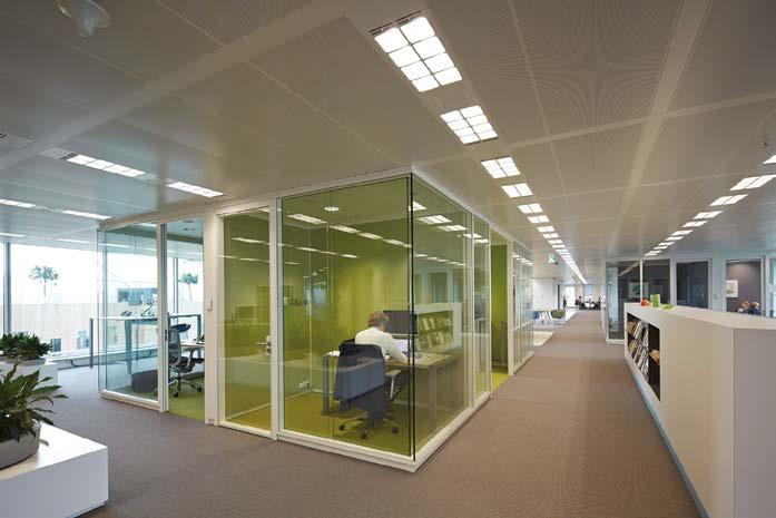
The Edge is a 40,000 m2 o ce building in Amsterdam’s Zuidas business district. One of its distinctive features is a smart lighting system, installed by Signify, formerly Philips Lighting. Nearly 6,500 connected LED luminaires create a digital lighting infrastructure throughout the 15-story building. Integrated sensors in the luminaires collect data on occupancy and light. is data allows facility managers to maximize e Edge’s operational e ciency and optimize o ce space, as well as reduce the building’s CO2 footprint. e result: a 3.6 million euro savings in space utilization and an annual reduction of 100,000 euros in energy costs. Creating such a large, distributed system is no small feat, Signify’s Peter Fitski points out. “ e luminaires each have their own controller, receiving a host of inputs from light switches and light and occupancy sensors. All these controllers talk to each other, share information via a lossy wireless network and act on it in a coordinated fashion. Our engineers develop the required functionality, lighting specialists design the desired environment and installation technicians make it work.”
Until recently, programming the individual building blocks, gluing them together and maintaining the resulting system were largely manual tasks, labor intensive and error prone. Together with ESI, the high-tech embedded systems joint innovation center of the Netherlands Organization for Applied Scientific Research (TNO), Signify started the public- private Prisma project to shine a light on the problem. is has resulted in tooling to streamline the development and deployment, which the Eindhoven company is now incorporating into its engineering process. Meanwhile, ESI is extending the solution to internet-of-things (IoT) applications in general.
Formal character
e Prisma tooling is based on so-called domain-speci c languages (DSLs). ese can be used by specialists, in this case
Credit: Signify




from the lighting domain, to specify a system using their own jargon, from which software can then be automatically generated. “With Signify, we identi ed three types of stakeholders: the installation technician, the lighting designer and the system de-


Prisma
Within the Prisma project, ESI (TNO) and Signify aimed to reduce the e ort for the full product lifecycle of distributed control systems: speci cation, development, validation, installation, commissioning and maintenance. e focus was on the lighting domain, with an extension to IoT applications in general. ESI participation was co-funded by Holland High Tech, Top Sector HTSM, with a public- private partnership grant for research and innovation.

Credit: Signify

veloper,” says ESI’s Jack Sleuters. “For each, we de ned a separate DSL.” e so-called building DSL lets the installation technicians write down what devices go where, in terms of luminaires, sensors, switches, groupings, rooms and such. Using the template DSL, the system developers can describe how the devices have to behave, independently of their number or location. e control DSL links the two, allowing the lighting designers to map the behavior to the physical space by indicating how the lighting changes, why, when and where. e big advantage of DSLs is their formal character. “We used to write down the behavior in plain English, also to align with our notso- technical colleagues,” illustrates Fitski. “But sometimes you make implicit assumptions or otherwise forget to include things. at became apparent when ESI looked at the documents and started asking questions like: ‘How does this work exactly?’ and ‘What happens in this case?’. e formal notation of a DSL forces you to be really precise about system behavior – it leaves no room for ambiguities.”
Plus, it talks the talk of the domain specialists. Worded in jargon, the speci cations are clear to all stakeholders. “We’ve formalized the lighting domain, so to say,” clari es Fitski. Sleuters adds: “And by staying on a relatively general level, you can talk about o ce behavior without having to know the details, so both an engineer and a marketeer can understand it – and each other.”
Zigbee and PoE
e Prisma project ran from 2015 to 2018. In the past two years, Signify has integrated the results into its way of working, with a primary focus on the template DSL to express behavior – the development side. “ ere, we felt the need the most,” notes Fitski. “We dove in deep. We started using the language and, step by step, developed it into something that can be easily applied in practice. One of the


According to Johan Knol, manager Failure Analysis, at least in his department, engineers are having to go well beyond their areas of focus and broaden their understanding of NXP’s entire production chain, especially as chip complexity continues to explode. Besides, eff iciency being key in an environment like this means every day you’re being challenged to do more in your daily eff orts.


For semiconductor giant NXP’s failure analysis department, training employees and broadening its knowledge base is instrumental in holding the leading. NXP had a shift from truly analog design to embedding digital more and more: mixed-signal designs.


nxp.com hightechinstitute.nl/time-management


things we did is create an automated translation from the high-level DSL to the low-level lighting controls.”
Signify engineers now have a toolchain at their disposal to automatically generate luminaire configurations. Fitski: “Based on the opensource Eclipse framework, we’ve built an editor with extensive error checking, in which we can specify lighting behavior using the template DSL. With the push of a button, the specifications are converted into configurations that can be sent to the luminaires. We’ve also added a graphical extension to visualize the programmed behavior.”
The luminaire configurations combine into recipes for complete lighting systems. “We’ve predefined a couple of recipes. They offer set behaviors with some configurability,” Fitski explains. “Once selected, a recipe is automatically transformed into the constituent configurations.”
Currently, the tooling supports two product lines: the luminaires that communicate wirelessly using the Zigbee protocol and those that are connected using Power over Ethernet (PoE) wires. “Starting from one and the same DSL instance, we can apply two transformations: one for the Zigbee implementation and one for the PoE implementation,” outlines Fitski. “Both are completely hardware independent. Within our Zigbee and PoE families, we have different controller types, but the generated implementations work on all of them.”

Broadening the scope
ESI, meanwhile, has also successfully built on the Prisma results. “You can do much more with the DSL framework,” states Sleuters. “We’re using it to create so-called virtual prototypes, for example. Once you’ve got a DSL description of your lighting system, you can simulate the complete behavior in a building. You can then walk customers through it at an early stage. By adding occupancy information, you can also make estimations about power consumption and optimize these by tweaking your model.”
Signify engineers can use the Prisma tooling to specify a lighting system in their own jargon, after which luminaire configurations can be generated automatically.
From a virtual prototype, it’s a relatively small step to a so-called digital twin – a digital copy that can be fed actual operational data from the real system. Sleuters: “If your model is correct, this should give you exactly the behavior you want. If not, you’ve uncovered an error and you can go and fix it.” Which is easier and cheaper to do in a digital-only system than when the hardware has already been set up.
More in the research realm, ESI has enhanced the Prisma framework with an even more powerful way to check for errors. “We’ve added a language to describe the system requirements on a high level,” says Sleuters. “From this description, a so-called model checker tool can determine whether a sequence of inputs and triggers exists that causes bad behavior. If it can’t find one, the system is guaranteed to work properly.”
Next to these developments, which are equally interesting for Signify to adopt, ESI is also taking Prisma out

High tech highlights
A series of public-private success stories by Bits&Chips
Credit: Signify
of lighting. As Sleuters and his colleagues have found the approach to be very useful for other connected large-scale distributed systems as well, they’ve broadened the scope to the IoT domain. “We’ve transformed the Prisma languages into a general IoT DSL. We’ve shown that it still works for the Signify case and we’re now looking to apply it to other areas, eg warehouse logistics – replacing luminaires and rooms with shuttles and conveyor belts.”
Practical use
The public-private collaboration has brought Signify valuable knowledge about DSLs. “This rather scientific world of formal languages and tooling is quite difficult to grasp,” Fitski finds. “Within our organization, we had some scattered experience in this area, but with the know-how of ESI and its network of partners, we’ve been able to put the technology to practical use.”
ESI’s Sleuters values the opportunity to do research in parallel to regular product development. “This industry-as-a-lab approach, as we call it, was picked up really well by Signify. There was broad support, from all levels in the organization.”
5G WILL SWING UP THE NUMBER OF IOT APPLICATIONS
All providers are about to introduce their 5G infrastructure. This super-fast network opens up a wealth of new possibilities, which all need electronic device support. More and more, NCAB’s James Wenzel sees electronic assemblies being built into applications that were never connected before.
James Wenzel
When the world wide web was introduced in the early nineties, the only device connected was a single personal computer. It took ten years before a couple of billion PCs were talking to each other over the internet. Still, communication and data entry were wholly dependent on human beings. It took another ten years before the Internet of Things (IoT) evolved into a system using multiple technologies, ranging from the internet to wireless communication and from microelectromechanical systems to embedded systems.
The traditional fields of automation, wireless sensor networks, GPS, control systems and others all support the IoT. A key improvement was the switch to IPv6 as the address limitations of previous internet protocols would have certainly blocked development. With IPv6, an almost unlimited amount of devices can be connected without any interference in the machine-to-machine communication. The “smart device” was born and it became quickly and quietly an important tool in our social and business environment.
IoT devices can now not only connect to regular 2G and 3G networks but also to Lorawan and LTE (4G). The various network characteristics define which option is best suited for the application. A gold transport truck, for example, requires real-time tracking for security, so LTE would be the network of choice. A GPS tracker on a sea container, on the other hand, only needs to provide its location once a day, so a connection to a Lorawan network would suffice. Another nice Lorawan example is the tracking of black rhinos in the Liwondo National Parks in Malawi.
A new era
The introduction of 5G opens up a completely new package of possibilities. Thanks to the low network latency, reliable real-time monitoring and control become feasible. Within milliseconds, the device that sent measurement data to the network receives instructions on what to do. We work very closely with several OEMs and EMS companies that provide the electronics for IoT devices. Delivering the PCBs for these devices, we’ve noticed a steady growth in 5G applications.
In the automotive industry, ultrareliable low-latency communication could support self-steering and accident-avoiding systems but also real-time traffic control. Tests of 5G-based speed regulation have proven to be very successful, reducing the number of traffic jams. Thanks to the real-time interaction between the various devices used in traffic control connected to the multimedia systems in the car, we’re on the eve of a new era.
Likewise, we see the rise of smart agriculture solutions and smart medical monitoring, where patients outside the hospital receive feedback on the medicine they’ve taken, as well as more and more 5G-based industrial IoT applications, eg for managing power distributions networks and harbor automation. Take a smart electricity grid with a highly variable energy production output, from sources including windmills and solar fields, which calls for real-time control and automation of the feeder line system. All these applications require ultrareliable low-latency communication.
James Wenzel is the CTO at NCAB Group Flatfield.
Edited by Nieke Roos
Aad Vredenbregt owns and runs Valoli.

Challenges put by the ubiquity of IoT devices
More than 16 years after the term’s first appearance, it’s still hard to find a comprehensive definition of the term “Internet of Things.” Around 2010, it started to gain popularity, replacing or supplementing “machine-to-machine” (M2M) communication.
That year, McKinsey wrote: “The physical world itself is becoming a type of information system. In what’s called the Internet of Things, sensors and actuators embedded in physical objects – from roadways to pacemakers – are linked through wired and wireless networks, often using the same Internet Protocol that connects the Internet.”
In that same period, market research company Gartner included “the Internet of Things” in its annual hype cycle for emerging technologies for the first time. Still, the IoT didn’t get widespread attention for some time and the concept only got public recognition by January 2014, when the IoT was a major theme at the Consumer Electronics Show (CES) in Las Vegas. Only by 2016 had the IoT become one of the most widely used concepts among tech communities, startup owners, as well as business tycoons.
An important facilitator in developing a functional IoT was IPv6’s step to increase address space. In addition, multilayer technologies were developed to manage and automate connected devices, so-called IoT platforms. They help bring physical objects online and contain a mixture of functions like sensors and controllers, a gateway device, a communication network, data analyzing and translating software and endapplication services.
Although the Internet of Things was initially associated with wearables, the number of applications has risen exponentially thanks to the convergence of cloud computing, mobile computing, embedded systems, big data, low-priced hardware and technological advances. Now, the IoT covers factories, retail environments and logistics, offices, home automation, smart cities and (autonomous)
Today’s influx of IoT devices has the effect of a digital tsunami
vehicles. It provides an endless supply of opportunities to interconnect devices and equipment.
Thus, the IoT is forcing existing companies into new business models and facilitating startups around the world. It offers enormous business opportunities, while at the same time creating potential security problems, as well as (asset) management challenges by its sheer numbers. The ubiquity of IoT devices in public and private environments has contributed to the aggregation and analysis of enormous amounts of data. How will we manage the explosion of IoT devices that sit all over the place, and the never-ending data streams that flow from those endpoints into the cloud?
Today’s influx of IoT devices, fueled by AI, blockchain and 5G technologies, has the effect of a digital tsunami. As the numbers keep growing, we should manage and secure each of these devices and the data they generate. If we don’t know what’s being connected to the digital environment, then we simply can’t manage those things. If we don’t know devices exist or don’t know their specifications, we won’t be able to bring them under control for monitoring and protection.
Last January, a hacker published on a forum a massive list of Telnet credentials for more than 515,000 Internet of Things devices. The list included each device’s IP address, along with a username and password for the Telnet service. The list was compiled by simply scanning the entire internet for devices that were exposing their Telnet port. The hacker then tried factory-set usernames and passwords or easy-to-guess password combinations.
There’s heterogeneous usage of IoT devices. While there may be little or no information available about device ownership, we need proper administration on status, functionality and location of each device. And not only within the enterprise domain. Just think about all devices installed in public spaces in the Netherlands: traffic surveillance, air quality measurement, safety cameras and so on.
The IoT world needs rigid asset management programs. As more and more devices become connected through digital supplements, we should develop the capability to effectively manage, deploy and secure them. Whether the device is a smart vending machine, a safety device, a doorbell cam, a smoke alarm or a sensor in a production machine.
PAVING NEW WAYS FOR NEXT-GEN IOT
In the last decade, a wide variety of Internet-of-Things technologies and applications has emerged, producing an ever-increasing stream of data. Neways is chipping in to create common IoT ground and control the floodgates.
Credit: Neways
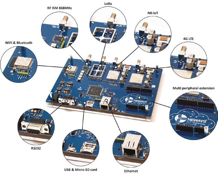
The gateway combines the most common wired and wireless interfaces with an on-board processing unit and expansion possibilities.
Nieke Roos
According to a recent study by Juniper Research, the global number of industrial connections to the Internet of Things will increase from 17.7 billion in 2020 to 36.8 billion in 2025. Smart manufacturing is identified as a key growth factor. As many of these industrial IoT systems use their own platforms, interoperability already is an issue, and with the ever-expanding network, it will only become a bigger challenge. There’s no global reference standard and none is foreseen soon.
Recognizing the need for an integrated approach, Neways Electronics International participated in the European Inter-IoT project, which ran from 2016 to 2019. This has resulted in a framework enabling interoperability among different IoT platforms, including a gateway for device-level support. Neways has taken it upon itself to further develop and market the hardware and software for this gateway, as part of an interoperable IoT platform. In parallel, it has embarked on a new European initiative, Assist-IoT. In November, this project has started work on a novel architectural approach for the next-generation IoT.
Building blocks
Continuously expanding its IoT capabilities, Neways has developed its IoT gateway to serve both as a technology
Credit: Neways
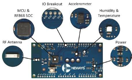
The generic sensor/actuator board serves as the basis for a motion sensor using a 3-axis accelerometer and an ultrasonic distance sensor.
showcase and as a prototyping platform with which it can quickly react to customer wishes. The gateway implements the most common wired and wireless interfaces. These are combined with an on-board processing unit and expansion possibilities. “At the moment, Ethernet, 868 MHz RF and Lora are supported,” says Dennis Engbers, team leader and senior software engineer at Neways in Enschede. “Work is ongoing to expand this with interfaces such as Bluetooth, 4G LTE, NB-IoT and Wi-Fi.”
The gateway stack is protocol agnostic, Engbers points out. “The stack abstracts away from the sensor and actuator protocols. At one end, it has a strict interface that the IoT devices need to implement and at the other, it has an interface to implement for connection to the middleware running in the cloud.”
As an electronics, embedded software and firmware developer, Neways
focuses on the IoT device layer, from the sensors and actuators up to and including the gateway. For this, it’s providing the building blocks ready for use in customer projects. “Think of such a building block as a board schematic and layout, plus the software drivers and the gateway stack,” clarifies Engbers. “For demonstration purposes, we’ve programmed our own Java middleware on top of this, but that’s not our core business. For commercial applications, we have specialist partners providing the layers from the middleware upwards.”
Smart office
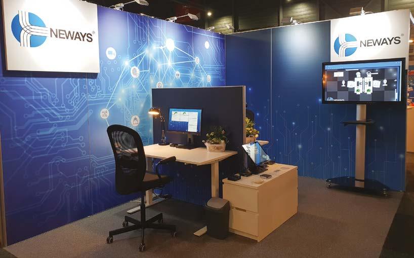
As part of Inter-IoT, Neways has built a smart office demonstrator, incorporating the gateway prototype. It showcases how multiple IoT technologies work together using the framework developed in the project. “The demonstrator features a touchscreen with a card reader where flex workers can sign in and reserve a desk,” illustrates Engbers. “The desk chairs contain motion sensors to monitor their ergonomic use. Level sensors in the trash cans indicate when they need to be emptied. We also measure the room temperature and humidity and the soil moisture of the office plants. All this data is combined and displayed in a dashboard.”
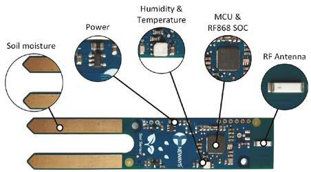
For this demonstrator, Neways developed a soil sensor, a generic sensor/actuator board and a shield board. The latter interfaces with a single-board computer acting as a device gateway. The sensor/actuator board serves as the basis for a motion sensor using a 3-axis accelerometer and an ultrasonic distance sensor.
The original demonstrator includes multiple gateways to capture the data
The smart office demonstrator showcases how different IoT technologies can be made to work together.
For the smart office demonstrator, Neways also developed a sensor to measure the soil moisture of plants.
Credit: Neways and relay it to the dashboard. They each run a different IoT solution, but they talk to the same Inter-IoT middleware through Inter-IoT APIs. A new demonstrator is currently in development that uses a single gateway to connect to all sensors and actuators and send their outputs to the middleware in the cloud.
Neways’ IoT gateway – acknowledged by the European Commission’s Innovation Radar as “market ready with a high potential of market creation with the innovation” – has also found its way to a first customer project. Here, Lora sensors are used to monitor the water quality in remote areas, which are frequently out of operators’ sight. Multiple gateway devices collect the measurement data and send it to the customer’s dashboard. The Lora functionality developed in this project has been incorporated as a building block in the gateway offering.
Decentralized approach
With its membership of the Assist-IoT consortium, which kicked off on 12 November and will run for three years, Neways is further expanding its IoT expertise. Engbers, explaining his company’s involvement: “IoT devices are now flooding the internet with data. They just pump everything into the cloud for analysis – without closer inspection. Assist-IoT is going to look at ways to make smarter decisions already at the edge, using machine learning and other artificial intelligence techniques to filter the data before it’s being sent over the network. Local analysis is faster because you don’t have to go to the cloud and back, and it saves bandwidth and cloud storage because you’re sending a lot less data.”
Assist-IoT will run three pilots. “In the Malta Freeport terminal, we aim to automate container logistics, using a decentralized edge approach and looking at the automated alignment of cargo-handling equipment, yard fleet assets location, augmented reality and tactile internet HMIs for fleet yard drivers and remote equipment control,” details Engbers. “With Ford, we’re going to dive into decentralized powertrain and vehicle condition monitoring. And on Polish construction sites, we’re looking to make the workplace safer and healthier by using smart IoT devices to control access to restricted zones, monitor the workers’ health parameters and identify suspicious and undesirable behavior.”
Although the project has just taken off, Neways already sees several applications for its results. “Take equipment manufacturers,” Engbers names a promising one. “They’re collecting loads and loads of data from their machines, sending everything over the internet for the purpose of health monitoring and preventive and predictive maintenance. By doing more at the edge, we can make these processes more efficient.”
How Simple and Secure Wi-Fi® IoT Nodes will Impact IIoT 4.0 Trends and Innovation
By Jacob Lunn Lassen, Sr. Marketing Manager for IoT and Functional Safety, Microchip Technology
What are (or will be) the issues of the Industry IoT market in 2021 in Microchip’s opinion?
One of the great challenges of industrial IoT (IIoT) 4.0 is to identify the “right application” and the “next big thing.” IIoT 4.0 is often talked about in general terms and for many industrial companies it is abstract – abstract in a way that makes it difficult to innovate. Often, conversations within the industry turn in the direction of “well, you can make connected sensors that measure ‘any’ kind of data in your facility.” This broad association to the technological marvel that is IIoT, hinders today’s customers from identifying the innovative and game-changing solutions that will help drive their productivity and quality - and competitiveness - to new levels. So, how can we open up the conversation to help better identify and advance a customer’s IoT needs?
Start small and iterate! Ask questions like, “what is the biggest head-ache with this part of the production line?” For example, if their answer is belt slippage that causes an unsteady flow of units, then the IIoT provider can offer specific sensors that check when slippage starts to occur. This would allow the customer to run the belt at the intended speed all the time, making adjustments as soon as the issue emerges. Planned maintenance and real-time adjustments are always less costly than unexpected line-down situations.
In Microchip’s opinion, what MCU function in the future will be required from Industrial automation market?
Sure … “just put together a couple of sensors!” It may sound simple, but it’s not. The reality is that rapid prototyping is necessary for rapid innovation, and the right building blocks are already available today, helping providers better identify their customer’s needs and customers better understand what providers and IIoT 4.0 have to offer for the efficiency of their facility. What features and advantages do Microchip’s MCU have?
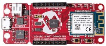
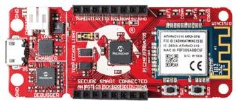
Microchip Technology’s AVR-IoT and PICIoT WG development boards have overcome the main obstacles that have, till now, limited the possibilities to accelerate prototyping and innovation in the IIoT environment.
With Wi-Fi connectivity, security and cloud connectivity, the AVR-IoT and PIC-IoT boards are a perfect starting point when connecting a variety of applications—ranging from wireless sensor nodes to intelligent lighting systems— to the cloud for remote command or control. With their combination of a powerful, yet simple, AVR® or PIC® microcontroller (MCU), a CryptoAuthentication™ secure element and a fully certified Wi-Fi network controller module, these plug-and-play boards make it easy to connect embedded applications to the Google Cloud. The Click™ connector makes them ideal for sensor prototyping, using existing Click modules or by adding the sensor type required to solve the engineering challenge at hand.
When using Microchip’s boards, the main connectivity and security obstacles are eliminated. Now developers can quickly design and evaluate new IIoT 4.0 concepts on a small scale in collaboration with industrial partners. This enables rapid learning and fast iterations, quickly and easily turning ideas and concepts into solutions. Rapid IIoT 4.0 prototyping optimizes a customer’s cost and efficiency greatly, with the potential to create a novel breakthrough in the way the industrial industry operates.
For design houses to be successful in driving the IIoT 4.0 innovation, it is important to partner with the right developers. Cloud and cloud processing require skilled software and web developers. And, as data goes from small to big, data analysts and AI experts will also be required. IIoT providers and industrial companies that do not adopt rapid prototyping to develop advanced automation and monitoring solutions are likely
AVR-IoT WG

PIC-IoT WG
to struggle in today’s competitive marketplace. Very few companies have the skills, time and money to create the secure WiFi solutions required to accelerate prototyping and IIoT 4.0 innovation. Therefore, adopting the building blocks, like Microchip’s AVR-IoT and PICIoT development boards, and harnessing the knowhow offered by the right developers, can greatly benefit those companies looking to excel in the industrial market. www.microchip.com
Cees Links is a Wi-Fi pioneer and the founder and CEO of Greenpeak Technologies and currently General Manager of Qorvo’s Wireless Connectivity business unit.

Wi-Fi 6 and CHIP: the ideal indoor couple?
The pandemic has more people working from home, and this has accelerated the adoption of WiFi 6. Consumers are upgrading home networks with this new, higher-speed standard and they’re enjoying the additional key benefits of its distributed architecture – ease of setup and high capacity that serves the needs of all family members – from video conferencing in the home office, to binge watching a favorite show in the living room, to hours of online gaming in an upstairs bedroom.
Wi-Fi 6’s distributed architecture brings a router and a set of satellites, or “pods,” which can be strategically positioned in the home. These pods connect themselves automatically to the main router, the one that connects to the outdoor internet, via a protocol called Wi-Fi Easymesh. The result is high-speed Wi-Fi through the whole house. Gone are the days when proximity to the router is crucial for performance and repeaters and/or powerline adapters are needed to cover the dead zones.
Although the term “pod” sounds rather simple, it could be a quite sophisticated device that can simultaneously do many other things. In fact, every non-mobile Wi-Fi device could function as a pod. A TV, a wireless speaker or smart assistants like Amazon’s Echo Dot or Google Home can simultaneously execute their own function and serve as a pod for other Wi-Fi devices. This is all on the drawing boards.
For a truly smart home, however, there’s another hurdle to overcome. Today, the IoT is serviced by multiple competing standards, representing different ecosystems, including Zigbee, BLE, Thread, Apple Homekit, Samsung’s Smart Things and Google’s Nest. This fragmentation has kept the IoT from living up to its potential as consumers wait for one overarching concept. Without one, the smart home is just a set of incoherent, stand-alone, special-purpose applications, unable to use each other’s data or availability.
The good news is called Connected Home over the Internet Protocol (CHIP). It’s more like a new aggregation standard than a new networking standard. Essentially, CHIP brings to-
Consumers are waiting for one overarching concept
gether the existing IoT standards. It’s a cooperation of the Zigbee Alliance and the Thread Alliance with Amazon, Apple, Google and Samsung, aggregating Zigbee, Thread, Bluetooth and Wi-Fi in one overarching standard.
CHIP will enable end-devices, the “things” of the IoT, to talk to the “pods” of the Wi-Fi 6 network – and via these pods, to the internet. The sensor endnode data can go where needed. This concept makes Wi-Fi 6 and CHIP an ideal couple for indoor connectivity.
Each Wi-Fi 6 pod will be equipped with a Zigbee radio, or better yet, a standard IEEE 802.15.4 (IoT) radio, next to the Wi-Fi radio. This allows all smart home devices (motion sensors, temperature sensors, open/close sensors) to connect to the Wi-Fi network and to the internet. With the popularity of Wi-Fi connectivity, there are already pods in many homes. Extending these with an IoT radio makes a lot of sense, and Wi-Fi 6 Easymesh automatically takes care of the rest. Some Wi-Fi router companies are already including CHIP radios (IEEE 802.15.4) in their products. This configuration will go mainstream when CHIP is formally announced.
And here’s more good news: CHIP end-devices themselves do not need to support meshing capabilities. With the full coverage Wi-Fi 6 provides, end-devices are always in range of a Wi-Fi pod. This means that CHIP end-devices will use significantly less power and enable smaller, longer-life batteries. The cost and design complexity of end-devices will be significantly reduced.
So where does this leave Bluetooth and BLE Mesh? That has yet to be seen. One could argue that Wi-Fi pods can just as easily be equipped with a BLE radio instead of an 802.15.4 radio. While that’s technically true, it’s not the most practical solution because Bluetooth itself is more a connectivity technology than for networking.
Look for an explosion of CHIP devices for Wi-Fi 6 on the market. In the perception of the consumer, everything in the home will be “Wi-Fi connected.” This will happen through Wi-Fi 6 Easymesh, and end-devices will talk to the Wi-Fi 6 network directly through a Wi-Fi radio (those end-devices with a keyboard and a screen) or via a smartphone setup and an IEEE 802.15.4 radio.
IOT AND PC-BASED CONTROL TO UTILIZE MANUFACTURING AND MACHINE DATA
Machines, devices and plants produce more and more data as they become smarter and more networked. Smart industry promises to turn these huge amounts of data into valuable information. Beckhoff and Mathworks show how this challenge can be tackled.
Fabian Bause Rainer Mümmler
Smart industry will transform familiar paradigms, such as the shape of the automation pyramid, which is now about a quarter-century old. As a model for automation in factories, the pyramid can be understood in several different ways. One of them is how data is exchanged and processed in automated environments.
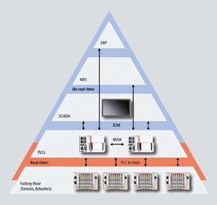
The automation pyramid comprises five layers, which can be divided into two sections. In the bottom section, we find the production process with sensors, actuators, drives, motors and tools in layer 0 doing the actual work and PLCs in layer 1 controlling the process. The top section forms the business management level, made up of Scada (layer 2), MES (layer 3) and the ERP system (layer 4).
From shop floor to business level
The pyramidal shape was chosen not only for hierarchical reasons but also because information travels horizontally and vertically. At the bottom, the amount of data produced is highest. The components in layer 0 communicate vertically in hard real time from different parts of the machine with the control layer at sample rates of up to some kilohertz, requiring field buses to transfer these enormous data streams. The buses used here include Ethercat, Profinet and Ethernet/IP.
The PLCs situated on layer 1 make sure that the intended process is executed with the right steps at the right time within the tolerances required. Horizontally, the controllers may communicate with each other either in real time, using Ethercat Automation Protocol (EAP) or UDP, or in non-real time, employing OPC-UA, ADS, TCP/IP and other protocols.
Moving up from the shop floor, business-to-machine communication starts. This communication usually isn’t real-time, since it typically relies on switches, routers, firewalls and other infrastructure devices that cause latencies. Traditionally, decisions are made more slowly toward the top of the pyramid and are based on increasingly condensed data.
A current trend in smart industry is to directly connect the MES and even the ERP to PLCs. These top layers now not only acquire data from the layers directly below them, where it has been reduced and analyzed, but may also send recipe data directly to PLCs and get status reports in return, paving the way for the flexibility and response times smart industry will require.
Taking automation to the business level
Future production and maintenance environments will have to cope with more and more plants being distributed across different sites, and machine builders will want to assess equipment running worldwide and offer maintenance contracts based on remote functionality. Establishing automated processes in layers 2 and 3 and interconnecting remote plants is therefore the future of automation. Production businesses and machine builders need to be able to do this efficiently and securely, ie without jeopardizing safe operation, network integrity and valuable confidential data.
A good entry point for engineers, production planning and machine builders is the Scada level (layer 2), where all the relevant production
The automation pyramid.
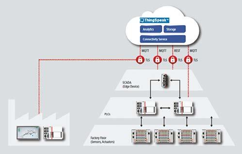
data arrives already reduced and is subsequently analyzed. A simple way to connect to external networks, and to add computing power, is to insert an edge device. By doing this at the Scada level, businesses will be able to concentrate their MES and ERP efforts at fewer sites or even a single site, where it’s easy to grant machine builders access to data from the shop floor and PLC levels but not to business and company data.
One approach to establishing secure connections between distributed factories is to employ VPNs, but setting up and maintaining them comes with several challenges. An alternative is to rely on cloud-based solutions that offer the advantages of secure data transport (like VPN) and minimize the disadvantages when it comes to maintaining the network connection.
Introducing Thingspeak
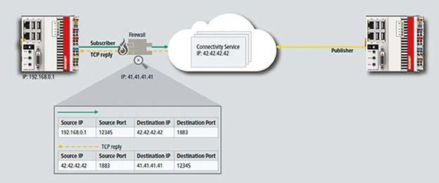
Cloud-based data communication often uses transport layer security (TLS). Traditionally, solutions of this kind work on a client/server basis. If an engineer wants to communicate with a PLC at a remote site, the PLC offering the data acts as the server and the user’s machine takes the role of a client, establishing a direct connection with the PLC. Securing this connection using TLS is no problem, but a port would need to be opened in the firewall for this kind of communication, which most IT admins will simply refuse.
The Thingspeak platform from Mathworks uses a publisher/ subscriber model to eliminate these limitations while offering additional benefits to the user. The Thingspeak
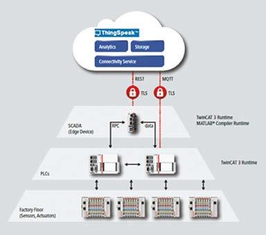
Connecting a Thingspeak server to the automation pyramid.
server can be placed in a secure network and act as a message broker so that any data published to it is sent through an outgoing connection only. Any subscriber will send its requests through an outgoing connection too, receiving data as a TCP reply (like a web browser).
This approach has advantages. Any parties to this communication only need to know the IP address of the message broker. There’s no need to disclose IP information of participants beyond the individual connection to the Thingspeak server. Adding new publishers and subscribers is straightforward, making the application flexible and scalable. Because any connection to the server is essentially an outgoing one, there are no additional firewall requirements, making it easy to integrate with existing IT infrastructures while at the same time keeping them secure.
Using Thingspeak
Thingspeak communication is based on easily configurable channels. These have read/write API keys and can be made public or private. Each channel contains eight fields to store eight streams of data, such as sensor readings, electrical signals or temperatures. The maximum update rate is once per second. Each field of each channel is provided with a default visualization that updates automatically as new data arrives.
To acquire data for these channels, Thingspeak offers Rest and MQTT APIs and specific hardware support. While the Rest API is platform specific, the MQTT API is general. MQTT’s only prerequisite is that the user specifies the correct payload format, making it easy to deploy for numerous applications and devices.
Once channel data is in Thingspeak, it can be stored in the cloud or immediately processed and visualized. The platform includes the ability to run Matlab code without the need for any further license. More than a dozen Matlab toolboxes provide functionality for statistics, analysis, signal processing, machine learning and more. Matlab scripts can be scheduled to run, enabling updated calculations and visualizations at fixed times.
Scripts can be inserted into Thingspeak by a simple copy-and-paste of Matlab code, which can – for ease of use, as well as for testing – be written on any desktop or laptop PC with a Matlab license. So Thingspeak becomes a natural cloud extension of the Matlab desktop.
The pyramid revisited
Thingspeak alone of course doesn’t guarantee a successful IoT environment, but it fits into one quite straightforwardly. To understand this, we need to take another look at data acquisition and processing in the pyramid.
On the factory floor, live data is processed locally on the controller in real time. This requires enormous bandwidth and therefore field buses with data rates of up to some gigabits per second, which Beckhoff offers by using port multipliers with standard 100 Mb/s Ethercat or by using Ethercat G with a 1 Gb/s data rate. The algorithms required can, for example, be developed in Matlab and Simulink and then integrated on the PLC using Matlab Coder and Simulink Coder,
Using the MQTT protocol to acquire data.
together with the target for Matlab/ Simulink for seamless integration into the automation software Twincat 3 from Beckhoff. This approach guarantees fast processing with deterministic response times and latencies in the range of sub-milliseconds required for real-time controlled processes. Applications for this kind of data processing are state monitoring, energy monitoring, vision applications and information compression.
The disadvantages of confining data processing to the PLC layer are that only one specific process can be monitored and controlled (without knowledge of adjacent processes, machines or equipment) and that only live data is used (no data histories). For this reason, data provided by more than one controller is often further processed at the Scada layer. This can be implemented on an edge device – for example, an industrial PC – that forms the link to Thingspeak. Such a structure enables stream processing, as well as comparison with stored data, which is quite different from the PLC layer, where data just streams along with virtually no storage.
Data processing on an edge device can combine high computing power and memory with high-bandwidth Gigabit LAN. However, it cannot produce deterministic response times and therefore cannot serve to control processes in real time. Again, the required code can be written in Matlab or generated from Simulink models. Deployment on the edge device (with Matlab Compiler) guarantees fast execution of runtime applications. Using the Twincat 3 interface for Matlab/ Simulink, fast communication can be established between the PLC layer and the Matlab Runtime on an edge device. The latter includes the possibility to represent functions written in Matlab as a callable function out of the PLC. Typical applications are cross-process statistics, model-based optimization, anomaly detection and again information compression.
All data processing described up to this point takes place locally in one closed network. Although this approach can give a comprehensive overview of one plant or site, it doesn’t allow for monitoring or control of processes distributed across various locations. This is a capability offered by Thingspeak.
Outside the traditional pyramid Because Thingspeak is connected to the edge device through an external network, data reduction is often necessary for bandwidth reasons. This reduction can be performed by algorithms readily integrated into the runtime application created by Matlab Compiler. Thingspeak can store or immediately process the incoming data stream. Information reduction can also be performed inside the PLC with integrated Matlab functionalities and a direct connection from the PLC to Thingspeak can be established. Due to latencies, as well as bandwidth limits, Thingspeak cannot
Processing data at the Scada layer (level 2, Twincat 3 Runtime) or on the edge device (Twincat 3 Runtime/ Matlab Compiler Runtime).
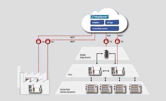
Using Thingspeak to monitor multiple plants and machines.
provide deterministic response times and real-time control.
Nonetheless, the benefits are huge. Integrating different processes is easy. The user only needs to specify the corresponding channels to start collecting data. This way, an arbitrary number of facilities can be connected to Thingspeak. Additionally, the storage capacity is much higher, allowing data histories to be saved to support maintenance and business decisions over long periods. This is interesting not only for production industries but also for equipment manufacturers, who can now monitor machines across the globe, offer maintenance contracts and compare performance based on environmental conditions, all from a single location.
Thingspeak also provides a serverless architecture. Though the Thingspeak cloud includes servers, they operate without any need for users to maintain or update them. The platform also comes with integrated Matlab and several toolboxes. The use of Matlab, in turn, enables users to extend their activities in Thingspeak to the desktop for algorithm and code development or deployment of real-time and runtime applications. This makes Thingspeak an effective link between a comprehensive modeling and design platform and industrial and scientific field applications, while at the same time enabling companies to leverage its capabilities for business uses.
Fabian Bause is a Twincat product manager at Beckhoff Automation. Rainer Mümmler is a principal application engineer at Mathworks.
Edited by Nieke Roos
Getting the data out

Angelo Hulshout has taken up the challenge to bring the benefi ts of production agility to the market and set up a new business around that. The fi rst challenge: getting the data out of the factory.
Angelo Hulshout
Last time, I wrote about my plans to set up a business around using data from factories to improve production and logistics processes. I also described the system needed to realize the idea.
At the bottom of this system, we nd the actual production equipment. ese are the machines and devices that form the actual physical production line. ey’re controlled by PLCs, soft PLCs or industrial controllers. e manufacturing execution system (MES) determines when and how the production line should run. Here, the entire factory process, from material intake up to release of the nal product, is controlled on a factory level. On top of the MES, enterprise resource planning (ERP) systems are used to plan production and logistic needs. Depending on the size of the manufacturing company and the industry branch, this is either done per factory or across factories.
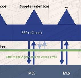
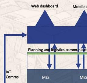


On top of all this, I want to put something I identify for now as ERP+, visualized as a layer going across factories. It uses the combination of data from equipment control, the MES and the ERP to allow for analysis and improvement of processes. Th is can be done by humans, in real time via mobile apps, or on a planning basis through dashboards. It can also be automated, by connecting to other systems and adding machine learning facilities.

Core problem
At the core of my solution is data from the production line. Th is data is available in the system but not always accessible automatically. Some of it is kept in spreadsheets and notes by operators, some of it is available in logs and databases and quite a bit is only collected when solving specifi c production issues. Th is makes it hard to determine where the relevant data is.
One aspect of collecting this data will need to be tackled regardless of that ‘relevant data’: getting it out of the equipment control layer. Depending on the age of a system, and the way data was considered at the time it was built, more or less data will be available in a processable form. In older factories – say before 2005, to set a date – a lot of equipment-level data isn’t available directly because it never leaves the equipment control layer.
What does that mean? On the MES level, production data and material logistics data will be available as they’re collected as part of the production process. Here, we’ll fi nd data about running and past production orders, errors that occurred during production and were corrected, orders that were aborted or canceled, and also the time needed to execute production orders.
What we often don’t fi nd is the equipment- level information about why things took shorter or longer and why they succeeded or failed. When a problem occurs, some information is sent ‘upwards’ towards the MES and the factory operator, but only just enough to solve the issue, after which the data is discarded or hidden somewhere in a log fi le.


Opening up
So, the fi rst technical challenge is getting the data out and into our ERP+. To open up the data in the factory, we’ll hook up the equipment control layer, the MES and the ERP to what we call an internet gateway, which will bridge the world inside the factory with the outside world. Th e big challenge there is to connect the equipment control layer. Most PLCs or industrial controllers can be connected to a network. However, some work needs to be done to open them up to the outside world.
A lot of these controllers run software that communicates with the actual hardware using low-level I/O signals and receives commands from the MES. Th ey don’t always keep track of when these signals are set and what their values are. To get access to this data (and later transform it into something useful), we aim to do two things.
First, since MES software is often more open to change or data access, we try to capture the commands from the MES layer – either by using the already existing logging and stored history or by adding the necessary data collection. Worst case, we’ll have to capture the commands on the physical (network or serial) connection to the controller and store them from there. Second, on the PLC itself, we can either add software to notify the MES (or a capture module we put in between) when a signal changes or capture the signal from the actual I/O signal. Th e latter we try to avoid, as it may aff ect the actual equipment operation. Adding this functionality in a non- invasive way isn’t easy, but as we’re working on this, the patterns to apply become clear.
Next steps
Th e next step is building a fi rst solution. Currently, we’re drawing up the concept for a fi rst customer, where we’ll have to focus on getting the data out. Subsequently, we’ll put a dashboard on top to allow human analysis and monitoring and defi ne what this customer needs to do after that.
Angelo Hulshout is an experienced independent software craftsman and a member of the Brainport High Tech Software Cluster. is is the second article in a series that’s going to follow his idea from inception, through startup to what he aims to make a successful company. In future contributions, he’ll dive deeper into de ning what the ‘right’ data is, the role of the industrial Internet of ings (IIoT) and machine learning in this concept and which technologies to use for that.
Edited by Nieke Roos


